EP2042965A2 - Procédé et appareil de conversion d'alimentation avec suivi des points d'alimentation maximum et capacité de mode rafale - Google Patents
Procédé et appareil de conversion d'alimentation avec suivi des points d'alimentation maximum et capacité de mode rafale Download PDFInfo
- Publication number
- EP2042965A2 EP2042965A2 EP20080017045 EP08017045A EP2042965A2 EP 2042965 A2 EP2042965 A2 EP 2042965A2 EP 20080017045 EP20080017045 EP 20080017045 EP 08017045 A EP08017045 A EP 08017045A EP 2042965 A2 EP2042965 A2 EP 2042965A2
- Authority
- EP
- European Patent Office
- Prior art keywords
- module
- power
- burst
- energy storage
- energy
- Prior art date
- Legal status (The legal status is an assumption and is not a legal conclusion. Google has not performed a legal analysis and makes no representation as to the accuracy of the status listed.)
- Withdrawn
Links
Images


Classifications
-
- G—PHYSICS
- G05—CONTROLLING; REGULATING
- G05F—SYSTEMS FOR REGULATING ELECTRIC OR MAGNETIC VARIABLES
- G05F1/00—Automatic systems in which deviations of an electric quantity from one or more predetermined values are detected at the output of the system and fed back to a device within the system to restore the detected quantity to its predetermined value or values, i.e. retroactive systems
- G05F1/66—Regulating electric power
- G05F1/67—Regulating electric power to the maximum power available from a generator, e.g. from solar cell
-
- H—ELECTRICITY
- H02—GENERATION; CONVERSION OR DISTRIBUTION OF ELECTRIC POWER
- H02J—CIRCUIT ARRANGEMENTS OR SYSTEMS FOR SUPPLYING OR DISTRIBUTING ELECTRIC POWER; SYSTEMS FOR STORING ELECTRIC ENERGY
- H02J3/00—Circuit arrangements for ac mains or ac distribution networks
- H02J3/38—Arrangements for parallely feeding a single network by two or more generators, converters or transformers
- H02J3/381—Dispersed generators
-
- H—ELECTRICITY
- H02—GENERATION; CONVERSION OR DISTRIBUTION OF ELECTRIC POWER
- H02J—CIRCUIT ARRANGEMENTS OR SYSTEMS FOR SUPPLYING OR DISTRIBUTING ELECTRIC POWER; SYSTEMS FOR STORING ELECTRIC ENERGY
- H02J3/00—Circuit arrangements for ac mains or ac distribution networks
- H02J3/38—Arrangements for parallely feeding a single network by two or more generators, converters or transformers
- H02J3/46—Controlling of the sharing of output between the generators, converters, or transformers
-
- H—ELECTRICITY
- H02—GENERATION; CONVERSION OR DISTRIBUTION OF ELECTRIC POWER
- H02J—CIRCUIT ARRANGEMENTS OR SYSTEMS FOR SUPPLYING OR DISTRIBUTING ELECTRIC POWER; SYSTEMS FOR STORING ELECTRIC ENERGY
- H02J2300/00—Systems for supplying or distributing electric power characterised by decentralized, dispersed, or local generation
- H02J2300/20—The dispersed energy generation being of renewable origin
- H02J2300/22—The renewable source being solar energy
- H02J2300/24—The renewable source being solar energy of photovoltaic origin
- H02J2300/26—The renewable source being solar energy of photovoltaic origin involving maximum power point tracking control for photovoltaic sources
-
- H—ELECTRICITY
- H02—GENERATION; CONVERSION OR DISTRIBUTION OF ELECTRIC POWER
- H02M—APPARATUS FOR CONVERSION BETWEEN AC AND AC, BETWEEN AC AND DC, OR BETWEEN DC AND DC, AND FOR USE WITH MAINS OR SIMILAR POWER SUPPLY SYSTEMS; CONVERSION OF DC OR AC INPUT POWER INTO SURGE OUTPUT POWER; CONTROL OR REGULATION THEREOF
- H02M1/00—Details of apparatus for conversion
- H02M1/0003—Details of control, feedback or regulation circuits
- H02M1/0032—Control circuits allowing low power mode operation, e.g. in standby mode
- H02M1/0035—Control circuits allowing low power mode operation, e.g. in standby mode using burst mode control
-
- Y—GENERAL TAGGING OF NEW TECHNOLOGICAL DEVELOPMENTS; GENERAL TAGGING OF CROSS-SECTIONAL TECHNOLOGIES SPANNING OVER SEVERAL SECTIONS OF THE IPC; TECHNICAL SUBJECTS COVERED BY FORMER USPC CROSS-REFERENCE ART COLLECTIONS [XRACs] AND DIGESTS
- Y02—TECHNOLOGIES OR APPLICATIONS FOR MITIGATION OR ADAPTATION AGAINST CLIMATE CHANGE
- Y02B—CLIMATE CHANGE MITIGATION TECHNOLOGIES RELATED TO BUILDINGS, e.g. HOUSING, HOUSE APPLIANCES OR RELATED END-USER APPLICATIONS
- Y02B70/00—Technologies for an efficient end-user side electric power management and consumption
- Y02B70/10—Technologies improving the efficiency by using switched-mode power supplies [SMPS], i.e. efficient power electronics conversion e.g. power factor correction or reduction of losses in power supplies or efficient standby modes
-
- Y—GENERAL TAGGING OF NEW TECHNOLOGICAL DEVELOPMENTS; GENERAL TAGGING OF CROSS-SECTIONAL TECHNOLOGIES SPANNING OVER SEVERAL SECTIONS OF THE IPC; TECHNICAL SUBJECTS COVERED BY FORMER USPC CROSS-REFERENCE ART COLLECTIONS [XRACs] AND DIGESTS
- Y02—TECHNOLOGIES OR APPLICATIONS FOR MITIGATION OR ADAPTATION AGAINST CLIMATE CHANGE
- Y02E—REDUCTION OF GREENHOUSE GAS [GHG] EMISSIONS, RELATED TO ENERGY GENERATION, TRANSMISSION OR DISTRIBUTION
- Y02E10/00—Energy generation through renewable energy sources
- Y02E10/50—Photovoltaic [PV] energy
- Y02E10/56—Power conversion systems, e.g. maximum power point trackers
Definitions
- Embodiments of the present disclosure generally relate to power conversion, and, more particularly, to a method and apparatus for power conversion with maximum power point tracking and burst mode capability.
- PV photovoltaic
- AC alternating current
- DG distributed generation
- PV modules have a nonlinear relationship between the current (I) and voltage (V) that they produce.
- a maximum power point (MPP) on an I-V curve for a PV module identifies the optimal operating point of the PV module; when operating at this point, the PV module generates the maximum possible output power for a given temperature and solar irradiance. Therefore, in order to optimize power drawn from a PV module, a power conversion device coupled to the PV module, such as an inverter, generally employs a maximum power point tracking (MPPT) technique to ensure that the PV module is operated at the current and voltage levels corresponding to its MPP.
- MPPT acts to rapidly adjust the PV module operating current and voltage levels in response to changes in solar irradiance and/or temperature such that the PV module can continue to operate at the MPP.
- a power conversion device coupled to the PV module will suffer from a lower efficiency until the MPP is achieved. Additionally, a power conversion device coupled to a PV module generally will suffer from a lower efficiency when the PV module is operating at a low power, i.e., low irradiance.
- a PV module and an associated inverter may operate so inefficiently that is it best for overall system efficiency to deactivate the PV module and/or its inverter until solar irradiance increases.
- Embodiments of the present invention generally relate to a method and apparatus for converting a DC input power to a DC output power.
- the apparatus comprises an energy storage module and a burst mode controller.
- the burst mode controller causes energy to be stored in the energy storage module during at least one storage period, and further causes the energy to be drawn from the energy storage module during at least one burst period. During the at least one burst period, the DC output power is greater than the DC input power.
- the burst mode controller employs a maximum power point tracking (MPPT) technique for operating a device providing the DC input power proximate a maximum power point (MPP).
- MPPT maximum power point tracking
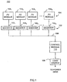
- FIG. 1 is a block diagram of a system for distributed generation (DG) in accordance with one or more embodiments of the present invention
- FIG. 2 is a block diagram of an inverter in accordance with one or more embodiments of the present invention.
- Figure 3 is a block diagram of a burst mode controller in accordance with one or more embodiments of the present invention.
- Figure 4 is a pair of graphical diagrams for determining a voltage swing range in accordance with one or more embodiments of the present invention
- Figure 5 is a pair of graphical diagrams showing simulated results of voltage and power levels in accordance with one or more embodiments of the present invention.
- FIG. 6 is a flow diagram of a method 600 for maximum power point tracking (MPPT) with burst mode in accordance with one or more embodiments of the present invention.
- MPPT maximum power point tracking
- FIG. 1 is a block diagram of a system 100 for distributed generation (DG) in accordance with one or more embodiments of the present invention. This diagram only portrays one variation of the myriad of possible system configurations.
- the present invention can function in a variety of distributed power generation environments and systems.
- the system 100 comprises a plurality of inverters 102 1 , 102 2 ... 102 n , collectively referred to as inverters 102, a plurality of PV modules 104 1 , 104 2 ... 104 n , collectively referred to as PV modules 104, an AC bus 106, a load center 108, and an array control module 110.
- Each inverter 102 1 , 102 2 ... 102 n is coupled to a P V module 104 1 , 1 0 4 2 ... 104 n , respectively.
- a DC-DC converter may be coupled between each P V module 104 and each inverter 102 (i.e., one converter per PV module 104).
- multiple PV modules 104 may be coupled to a single inverter 102; in some embodiments, a DC-DC converter may be coupled between the PV modules 104 and the single inverter 102.
- Each inverter 102 employs an MPPT technique to operate the subtending PV module 104 at its MPP such that the PV module 104 generates an optimal power output for a given temperature and solar irradiation.
- the inverters 102 are further coupled to the AC bus 106, which in turn is coupled to the load center 108.
- the load center 108 houses connections between incoming power lines from a commercial power grid distribution system and the AC bus 106.
- the inverters 102 convert DC power generated by the PV modules 104 into AC power, and meter out AC current that is in-phase with the AC commercial power grid voltage.
- the system 100 couples the generated AC power to the commercial power grid via the load center 108.
- a control module 110 is coupled to the AC bus 106.
- the control module 110 is capable of issuing command and control signals to the inverters 102 in order to control the functionality of the inverters 102.
- the inverters 102 employ a "burst mode" during initial operation and during periods of low power output from the PV modules 104.
- burst mode the inverters 102 store energy over one or more commercial power grid cycles, and, upon sufficient energy being stored, "burst" the stored energy to the commercial power grid.
- the burst mode facilitates a rapid convergence to the MPP by an MPPT technique described below.
- the inverters 102 switch from the burst mode to a steady-state mode, utilizing the MPPT technique to remain at the MPP. In the event that the solar irradiance and/or temperature changes to a level that cannot sustain MPPT operation, one or more of the inverters 102 switch back to burst mode.
- FIG. 2 is a block diagram of an inverter 102 in accordance with one or more embodiments of the present invention.
- the inverter 102 comprises an I-V monitoring circuit 202, an energy storage module 204, a DC-AC inverter 210, a burst mode controller 212, and a conversion control module 214.
- the inverter 102 is coupled to the PV module 104 and to the commercial power grid.
- a DC-DC converter may be coupled between the PV module 104 and the inverter 102.
- the I-V monitoring circuit 202 is coupled to the burst mode controller 212, across two output terminals of the PV module 104, and across two terminals of the energy storage module 204; the energy storage module 204 is further coupled across two terminals of the DC-AC inverter 210.
- the burst mode controller 212 is further coupled to the conversion control module 214 and to the DC-AC inverter 210.
- the I-V monitoring circuit 202 monitors the instantaneous voltage and current output levels, V PV and I PV , respectively, from the PV module 104, and provides a signal indicative of such current and voltage information to the burst mode controller 212.
- the burst mode controller 212 utilizes the current and voltage information from the I-V monitoring circuit 202 to switch the inverter 102 between continuous mode and burst mode.
- the burst mode controller 212 drives the inverter 102 such that energy generated by the PV module 104 is stored in the energy storage module 204 during energy storage periods, and the stored energy is dispensed to the DC-AC inverter 210 during burst periods.
- the energy storage module 204 comprises a capacitor.
- the DC-AC inverter 210 is coupled to the conversion control module 214.
- the conversion control module 214 receives a reference signal input from the commercial power grid, and provides the control signals for the DC-AC inverter 210 to convert DC power received through the I-V monitoring circuit 202 and energy storage module 204 to AC power.
- the resulting output current from the inverter 102 is coupled to the commercial power grid such that it is in-phase with the commercial AC current.
- the inverter 102 Upon initial operation or being unable to operate at the MPP, the inverter 102 operates in burst mode, wherein during an energy storage period (e.g., one or more AC grid waveform cycles of 16.67 msec) the energy storage module 204 stores energy that is subsequently sent to the DC-AC inverter 210 during a burst period (i.e., once significant energy has been stored).
- the burst mode controller 212 drives the inverter 102 during burst mode to achieve such energy storage and utilization. During energy storage periods, the burst mode controller 212 drives the inverter 102 such that no output current is produced.
- the energy storage module 204 comprises a capacitor, and the current generated by the PV module 104 charges the capacitor during the energy storage period.
- the burst mode controller 212 drives the inverter 102 to generate a burst current, I B , where I B is greater than the normal output current generated by the inverter 102 during a steady state (i.e., non-burst) operating mode.
- the current I B results in an output power from the inverter 102 greater than the input power supplied by the PV module 104 alone.
- the energy stored in the energy storage module 204 compensates for the power deficit from the PV module 104, and the coupling of energy to the DC-AC inverter 210 results in a voltage drop across the energy storage module 204 and a corresponding voltage drop across the PV module 104.
- the burst mode controller 212 drives the inverter 102 such that no output current is produced (i.e., an energy storage period), and energy from the PV module 104 is again stored in the energy storage module 204 until such time that sufficient energy is available to generate another burst.
- a Power-Voltage (P-V) curve depicts output power from a PV module, such as the PV module 104, as a function of the PV module operating voltage.
- the P-V curve will have a single peak identifying the maximum possible PV module output power and the corresponding operating voltage (i.e., the MPP).
- the slope of the P-V curve, ⁇ P/ ⁇ V, to the left of the MPP has a positive value that decreases in magnitude until it reaches zero at the MPP; moving to the right of the MPP (i.e., the right-plane of the P-V curve), ⁇ P/ ⁇ V has a negative increasing value.
- the burst mode controller 212 drives the inverter 102 to produce a required output current, I req .
- a ripple voltage present across the energy storage module 204 provides a small voltage "sweeping" such that the ⁇ P/ ⁇ V can continue to be monitored and I req adjusted according to continue operating the PV module 104 at the MPP.
- FIG. 3 is a block diagram of a burst mode controller 212 in accordance with one or more embodiments of the present invention.
- the burst mode controller 212 comprises a multiplier 302, an MPPT module 304, two adders 306 and 308, a burst activation controller 310, a scaling module 312, a burst current controller 314, and a switch module 316.
- the multiplier 302 is coupled to the I-V monitoring circuit 202 such that it receives a sampling of the PV module instantaneous output voltage and current, V PV and I PV respectively, from the I-V monitoring circuit 202.
- the resulting output of the multiplier 302 provides a measure of the instantaneous power generated by the PV module 104, P PV , and is coupled to the MPPT module 304.
- the MPPT module 304 is coupled to the I-V monitoring circuit 202 and receives a signal indicative of the PV module instantaneous output voltage V PV .
- the MPPT module 304 receives an input signal indicative of the commercial power grid cycle from the conversion control module 214, for example from a phase lock loop of the conversion control module 214, and is further coupled to the scaling module 312, the burst current controller 314, and each of the adders 306 and 308.
- the MPPT module 304 computes the change in PV module output power with respect to the change in PV module operating voltage, ⁇ P/ ⁇ V. For example, for a 60 Hz commercial power grid, the MPPT module 304 computes the ⁇ P/ ⁇ V during each 16.67 msec cycle of the commercial power grid. Based on the computed ⁇ P/ ⁇ V, the MPPT module 304 determines a required adjustment to the PV module operating voltage in order to approach the MPP and the corresponding desired PV module operating voltage.
- ⁇ P/ ⁇ V In the case where ⁇ P/ ⁇ V is greater than zero, i.e., the operating voltage is in the left-plane of the P-V curve, the operating voltage must be increased to reach the MPP; if ⁇ P/ ⁇ V is less than zero, i.e., the operating voltage is in the right-plane of the P-V curve, the operating voltage must be decreased. Additionally, as the operating voltage approaches the MPP voltage and the magnitude of ⁇ P/ ⁇ V can be seen to decrease, smaller adjustments can be made to the operating voltage to ensure a graceful convergence to the MPP voltage.
- the MPPT module 304 provides a signal indicative of the new desired PV module operating voltage to the scaling module 312 and to each of the adders 306 and 308.
- a small positive voltage, + ⁇ V is provided as an input to the adder 308; the resulting output is a high voltage threshold, V H .
- a small negative voltage - ⁇ V is provided as an input to the adder 306; the resulting output is a low voltage threshold, V L .
- + ⁇ V and - ⁇ V are of the same magnitude; in alternative embodiments, they may have different magnitudes.
- the outputs of the adders 306 and 308 are each coupled to the burst activation controller 310.
- the burst activation controller 310 is coupled to the I-V monitoring circuit 202 such that it receives the instantaneous PV module operating voltage V PV .
- the burst activation controller 310 utilizes the V PV , V H , and V L information, as described below, to switch between energy storage and burst periods.
- the scaling module 312 receives an input of a burst power level, P B .
- Two output terminals of the scaling module 312 are coupled to the switch module 316, and the switch module 316 is further coupled to the burst current controller 314 and to the DC-AC inverter 210.
- the inverter 102 operates in continuous mode and the burst current controller 314 drives the switch module 316 to select the output from a second output terminal of the scaling module 312 for driving the DC-AC inverter 210 to generate a continuous mode output current, I req .
- the scaling module 312 receives an input indicative of the average PV module operating voltage and the desired PV module operating voltage from the MPPT module 304. Based on the error between the average PV module operating voltage and the desired PV module operating voltage, the scaling module 312 determines the required inverter output current I req that will result in biasing the PV module 104 at the desired operating voltage.
- the inverter 102 When the PV module output power is lower than the burst mode threshold level, the inverter 102 operates in burst mode, and the burst current controller 314 drives the switch module 316 to select the output from a first output terminal of the scaling module 312 for driving the DC-AC inverter 210 to generate a burst current, I B .
- the burst activation controller 310 drives the scaling module such that I B is set to zero; as a result, the inverter 102 produces no output power and energy generated by the PV module 104 is stored in the energy storage module 204. Such energy storage results in a rising voltage across the energy storage module 204 and a corresponding rising PV module voltage, V PV .
- the burst activation controller 310 compares the instantaneous PV module operating voltage V PV to the high and low voltage thresholds, V H and V L , computed during the previous grid cycle. If V PV exceeds V H , sufficient energy has been stored in the energy storage module 204 to generate a burst. The burst activation controller 310 then drives the scaling module 312 to set I B to a maximum value such that stored energy is drawn from the energy storage module 204.
- the burst activation controller 310 drives the scaling module such that I B is set to a maximum value.
- the DC-AC inverter 102 draws the stored energy from the energy storage module 204, resulting in a voltage drop across the energy storage module 204 and a corresponding voltage drop in the PV module voltage V PV .
- V PV voltage drop across the energy storage module 204
- V L voltage drop across the PV module voltage
- the energy storage and burst periods during burst mode allow sufficient energy to be stored in and drawn from the energy storage module 204 to provide a "burst" of additional power to the DC-AC inverter 210, thereby improving the efficiency of the inverter 102 during periods when the PV module 104 is operating at a low power level. Additionally, during burst mode the PV module voltage V PV "swings" between V L and V H , causing the PV module output power to change accordingly and allowing the burst mode controller 212 to monitor the ⁇ P/ ⁇ V and suitably adjust the PV module operating voltage for efficient MPPT operation. Once the MPP voltage has been reached, the inverter 102 can switch from burst mode to continuous mode, or, if the PV module output power remains below the burst mode threshold, the inverter 102 can remain in burst mode.
- the selected output from the scaling module 312 drives the DC-AC inverter 210 to generate the continuous mode output current I req .
- a ripple voltage present across the energy storage module 204 results in a small voltage swing in the PV module operating voltage V PV . This small voltage swing and the corresponding change in the PV module output power allows the MPPT module 304 to continue to compute the ⁇ P/ ⁇ V and generate the required PV module operating voltage adjustments to maintain operation at the MPP.
- Figure 4 is a pair of graphical diagrams 402 and 404 for determining a voltage swing range in accordance with one or more embodiments of the present invention.
- the graphs 402 and 404 depict a voltage level across the energy storage module204 and a corresponding output power level of the inverter 102, respectively, during burst mode.
- the inverter 102 From time T 1 to T 2 , the inverter 102 operates during an energy storage period, allowing the energy storage module 204 to charge and resulting in the rising voltage level across the energy storage module 204, as depicted in graph 402. During the energy storage period, no input power is provided to the DC-AC inverter 210, and the corresponding output power level of the inverter 102 from time T 1 to T 2 can be seen to be zero.
- the energy stored in the energy storage module204 has reached a level sufficient to trigger a burst period.
- the inverter 102 is driven to generate a burst mode output power level P B , as depicted in graph 404.
- P B burst mode output power level
- the voltage level across the energy storage module204 drops, as depicted in graph 402.
- the voltage level across the energy storage module 204 drops to a level sufficient to necessitate an energy storage period, and the output power level of the inverter 102drops to zero as the energy storage period begins.
- the voltage level across the energy storage module 204 can be seen to "swing" by a small amount, ⁇ V, around a center voltage of V center .
- ⁇ V the voltage across the energy storage module 204 becomes greater than V center + ⁇ V
- the inverter 102 generates a burst and produces an output power that is coupled to the commercial power grid.
- the inverter 102 drops below V center - ⁇ V
- the inverter 102 begins an energy storage period and produces no output power.
- the value of ⁇ V determines when the inverter 102 is in a burst period or an energy storage period, and thereby determines when output power from the inverter 102 is coupled to the commercial power grid.
- the voltage swing around the center voltage V center may be determined as follows. Utilizing a known average voltage across the energy storage module 204, V center , and a known average burst power, P B , the time from T 2 to T 3 , or T on , can be estimated as follows based on V center >> ⁇ V >> ripple voltage across the energy storage module 204 and + ⁇ V having the same magnitude as - ⁇ V:
- T on can be shown as:
- T On 2 ⁇ C ⁇ ⁇ ⁇ V 2 center P B - P Avg
- T on In order to efficiently coupled power produced by the inverter 102 to the commercial power grid, T on must be an integer number "n" grid cycles; in some embodiments, T on must therefore be equal to 16.67n msec.
- the voltage swing required to achieve such a T on can be determined as follows:
- Figure 5 is a pair of graphical diagrams 502 and 504 showing simulated results of voltage and power levels in accordance with one or more embodiments of the present invention.
- the graph 502 depicts the simulated voltage level across the energy storage module 204 during burst mode, and the graph 504 depicts the simulated corresponding output power of the inverter 102.
- the inverter 102 is in an energy storage period.
- the burst current I B is set to zero, allowing the energy storage module 204 to charge and resulting in the rising voltage level across the energy storage module 204, as depicted in graph 502.
- the energy storage period results in no input power to the DC-AC inverter 210; accordingly, no power is generated by the inverter 102, and the corresponding power output from time T 1 to T 2 can be seen to be zero.
- the energy stored in the energy storage module 204 has reached a level sufficient to generate a burst, and the burst current I B is generated by the inverter 102 as previously described.
- the voltage level across the energy storage module 204 drops; additionally, a "ripple" voltage can be seen across the energy storage module 204, as depicted in graph 502.
- the inverter 102 generates output power as depicted in graph 504.
- the energy drawn from the energy storage module 204 has reduced the voltage across the energy storage module 204 to a level requiring the inverter 102 to enter an energy storage period, and the burst current I B is set to zero. Accordingly, the output power of the inverter 102 falls to zero at time T 3 .
- the energy storage module204 begins to charge again, resulting in the rising voltage level across the energy storage module 204 depicted in graph 502.
- the energy stored in the energy storage module 204 has again reached a sufficient level to enter a burst period and the burst current I B is again set to a maximum value.
- the voltage level across the energy storage module 204 drops as the energy in the energy storage module 204 is utilized, and the inverter 102 again generates an output power.
- FIG. 6 is a flow diagram of a method 600 for maximum power point tracking (MPPT) with burst mode in accordance with one or more embodiments of the present invention.
- an inverter is coupled to a PV module for converting DC power generated by the PV module to AC power.
- the inverter is further coupled to a commercial power grid such that the AC power produced is coupled to the commercial power grid in-phase with the commercial AC power.
- multiple PV modules may be coupled to a single centralized DC-AC inverter; alternatively, individual PV modules may be coupled to individual DC-AC inverters (e.g., one PV module per DC-AC inverter).
- a DC-DC converter may be coupled between the PV module or PV modules and the DC-AC inverter.
- the method 600 beings at step 602 and proceeds to step 604.
- the inverter operates in burst mode during an energy storage period
- the inverter may operate in burst mode due to very low power produced by the PV module, such as during periods of little solar irradiance.
- the inverter stores energy that is produced by the PV module; in some embodiments, an energy storage module, such as a capacitor, is utilized to store the energy.
- the method 600 proceeds to step 606, where it is determined whether energy stored in the inverter has reached a level sufficient to enter a burst period and begin generating output power. In some embodiments, such a determination is made based on a voltage across the energy storage module of the inverter satisfying a first threshold.
- V center is an average operating voltage of the PV module, and is equivalent to an average operating voltage of the energy storage module.
- step 606 the method 600 returns to step 604. If the condition at step 606 is satisfied, the method 600 proceeds to step 608.
- the inverter enters the burst period. During the burst period, the inverter is driven to produce a burst current, I B , where I B is greater than the current level that would be normally achieved utilizing only the instantaneous power generated by the PV module. Generating the burst output current I B draws upon the energy stored in the inverter; in some embodiments, such utilization results in a voltage drop across the energy storage module of the inverter and a corresponding voltage drop across the PV module.
- the method 600 proceeds to step 610, where the instantaneous power produced by the PV module and the corresponding PV module operating voltage are measured over one cycle of the commercial power grid.
- the commercial power grid operates at 60Hz and the instantaneous power and operating voltage are measured over 16.67 msec.
- the method 600 proceeds to step 612, where the change in PV module output power with respect to the change in PV module operating voltage, ⁇ P/ ⁇ V, is computed.
- step 618 an adjustment to the PV module operating voltage is determined based on the ⁇ P/ ⁇ V, where such adjustment drives the PV module operating voltage toward the MPP operating voltage. In some embodiments, if the ⁇ P/ ⁇ V is positive, the PV module operating voltage must be adjusted positively; if the ⁇ P/ ⁇ V is negative, the PV module operating voltage must be adjusted negatively. The required adjustment to the PV module operating voltage defines a new desired PV module operating voltage.
- the inverter is driven to generate a burst mode current, I B , where I B results in driving the PV module to the new desired operating voltage.
- V center is set to the new desired operating voltage, and at step 624, new high and low voltage thresholds, V H and V L , are determined based on the new V center .
- the method 600 returns to step 608, where the inverter continues the burst period.
- step 626 a determination is made whether the PV module output power satisfies a power threshold. If the PV module output power does not satisfy the power threshold, the inverter will suffer from a low efficiency and therefore requires continued operation in burst mode to improve the efficiency. If the PV module is producing power at a sufficient level, burst mode is no longer required. In some embodiments, a power threshold of 30% of the power rating of the PV module is utilized.
- step 626 the method 600 returns to step 604 for continued operation in burst mode. If the condition at step 626 is satisfied, the method 600 proceeds to step 628.
- step 628 the inverter switches from burst mode and operates in a steady-state, or continuous, mode. During such operation, the inverter is driven to produce an output current, I req .
- a ripple voltage across the energy storage module provides a corresponding voltage "sweeping" across the PV module. Such a sweeping provides an opportunity to compute the ⁇ P/ ⁇ V during each cycle of the commercial power grid and to adjust the I req accordingly to bias the PV module at the MPP for continued MPPT operation.
Landscapes
- Engineering & Computer Science (AREA)
- Power Engineering (AREA)
- Electromagnetism (AREA)
- Sustainable Energy (AREA)
- Sustainable Development (AREA)
- Physics & Mathematics (AREA)
- Life Sciences & Earth Sciences (AREA)
- General Physics & Mathematics (AREA)
- Radar, Positioning & Navigation (AREA)
- Automation & Control Theory (AREA)
- Inverter Devices (AREA)
- Supply And Distribution Of Alternating Current (AREA)
- Charge And Discharge Circuits For Batteries Or The Like (AREA)
- Control Of Electrical Variables (AREA)
- Dc-Dc Converters (AREA)
Applications Claiming Priority (1)
| Application Number | Priority Date | Filing Date | Title |
|---|---|---|---|
| US99540907P | 2007-09-26 | 2007-09-26 |
Publications (2)
| Publication Number | Publication Date |
|---|---|
| EP2042965A2 true EP2042965A2 (fr) | 2009-04-01 |
| EP2042965A3 EP2042965A3 (fr) | 2016-07-27 |
Family
ID=40219445
Family Applications (1)
| Application Number | Title | Priority Date | Filing Date |
|---|---|---|---|
| EP08017045.9A Withdrawn EP2042965A3 (fr) | 2007-09-26 | 2008-09-26 | Procédé et appareil de conversion d'alimentation avec suivi des points d'alimentation maximum et capacité de mode rafale |
Country Status (3)
| Country | Link |
|---|---|
| US (1) | US7986122B2 (fr) |
| EP (1) | EP2042965A3 (fr) |
| JP (1) | JP5455184B2 (fr) |
Cited By (7)
| Publication number | Priority date | Publication date | Assignee | Title |
|---|---|---|---|---|
| EP2345143A2 (fr) * | 2008-10-10 | 2011-07-20 | Enphase Energy, Inc. | Procédé et appareil pour mode rafale amélioré pendant une conversion électrique |
| EP2553790A1 (fr) * | 2010-03-31 | 2013-02-06 | Shenzhen BYD Auto R&D Company Limited | Système domestique de commande de l'énergie et procédé de commande pour celui-ci |
| US20140214230A1 (en) * | 2013-01-28 | 2014-07-31 | General Electric Company | Systems and methods for maximum power point tracking in a micro inverter |
| EP2717447A3 (fr) * | 2012-10-05 | 2017-01-11 | Linear Technology Corporation | Système et procédé de régulation de la tension d'alimentations à découpage avec fonctionnement en mode rafales |
| EP2547175A4 (fr) * | 2010-03-11 | 2017-07-26 | Rohm Co., Ltd. | Système d'éclairage |
| US10193347B2 (en) | 2013-03-29 | 2019-01-29 | Enphase Energy, Inc. | Method and apparatus for improved burst mode during power conversion |
| US10488879B2 (en) | 2017-03-09 | 2019-11-26 | Ecole Polytechnique Federale De Lausanne (Epfl) | Device and method for performing maximum power point tracking for photovoltaic devices in presence of hysteresis |
Families Citing this family (54)
| Publication number | Priority date | Publication date | Assignee | Title |
|---|---|---|---|---|
| US7994657B2 (en) * | 2006-12-22 | 2011-08-09 | Solarbridge Technologies, Inc. | Modular system for unattended energy generation and storage |
| US7755916B2 (en) | 2007-10-11 | 2010-07-13 | Solarbridge Technologies, Inc. | Methods for minimizing double-frequency ripple power in single-phase power conditioners |
| MX2010010380A (es) * | 2008-03-25 | 2010-12-15 | Delta Electronics Inc | Un sistema convertidor de energia que opera eficientemente sobre un intervalo de condiciones de carga. |
| US8014176B2 (en) * | 2008-07-25 | 2011-09-06 | Cirrus Logic, Inc. | Resonant switching power converter with burst mode transition shaping |
| EP2319079A4 (fr) * | 2008-08-01 | 2014-01-01 | Petra Solar Inc | Système et procédé de production d'électricité solaire distribuée sur poteau électrique |
| US9093862B2 (en) * | 2009-01-16 | 2015-07-28 | Zbb Energy Corporation | Method and apparatus for controlling a hybrid power system |
| US8666561B2 (en) * | 2009-02-05 | 2014-03-04 | Enphase Energy, Inc. | Method and apparatus for determining a corrected monitoring voltage |
| EP2415146A1 (fr) | 2009-04-01 | 2012-02-08 | Nextronex Inc. | Système solaire raccordé au réseau et procédé |
| CN101877494B (zh) * | 2009-04-30 | 2013-11-06 | 鸿富锦精密工业(深圳)有限公司 | 太阳能储能系统及其方法 |
| US8482947B2 (en) | 2009-07-31 | 2013-07-09 | Solarbridge Technologies, Inc. | Apparatus and method for controlling DC-AC power conversion |
| US8462518B2 (en) * | 2009-10-12 | 2013-06-11 | Solarbridge Technologies, Inc. | Power inverter docking system for photovoltaic modules |
| CN102044883B (zh) * | 2009-10-12 | 2014-12-10 | 盈威力新能源科技(上海)有限公司 | 一种单级式光伏并网逆变器的最大功率点跟踪的优化方法 |
| US8824178B1 (en) | 2009-12-31 | 2014-09-02 | Solarbridge Technologies, Inc. | Parallel power converter topology |
| KR101035402B1 (ko) * | 2010-01-18 | 2011-05-20 | 충북대학교 산학협력단 | 열전 발전 소자의 최대 전력점 구동 회로 |
| US8772965B2 (en) | 2010-06-29 | 2014-07-08 | General Electric Company | Solar power generation system and method |
| CN102136734B (zh) * | 2010-09-08 | 2013-01-02 | 上海岩芯电子科技有限公司 | 一种光伏微型并网逆变器最大功率点跟踪方法 |
| US9160408B2 (en) | 2010-10-11 | 2015-10-13 | Sunpower Corporation | System and method for establishing communication with an array of inverters |
| US8503200B2 (en) | 2010-10-11 | 2013-08-06 | Solarbridge Technologies, Inc. | Quadrature-corrected feedforward control apparatus and method for DC-AC power conversion |
| US8279649B2 (en) | 2010-10-11 | 2012-10-02 | Solarbridge Technologies, Inc. | Apparatus and method for controlling a power inverter |
| US8842454B2 (en) | 2010-11-29 | 2014-09-23 | Solarbridge Technologies, Inc. | Inverter array with localized inverter control |
| US9467063B2 (en) | 2010-11-29 | 2016-10-11 | Sunpower Corporation | Technologies for interleaved control of an inverter array |
| US8970068B2 (en) | 2011-02-10 | 2015-03-03 | Draker, Inc. | Pseudo-random bit sequence generation for maximum power point tracking in photovoltaic arrays |
| CN102684241B (zh) * | 2011-03-16 | 2015-04-01 | 台达电子工业股份有限公司 | 太阳能逆变器和太阳能逆变器的控制方法 |
| US8612782B2 (en) * | 2011-03-31 | 2013-12-17 | Intel Corporation | System and method for determining multiple power levels of the sub-systems based on a detected available power and prestored power setting information of a plurality of different combinations of the sub-systems |
| US9065354B2 (en) | 2011-04-27 | 2015-06-23 | Sunpower Corporation | Multi-stage power inverter for power bus communication |
| US8611107B2 (en) | 2011-04-27 | 2013-12-17 | Solarbridge Technologies, Inc. | Method and system for controlling a multi-stage power inverter |
| US8193788B2 (en) | 2011-04-27 | 2012-06-05 | Solarbridge Technologies, Inc. | Method and device for controlling a configurable power supply to provide AC and/or DC power output |
| CN102200793A (zh) * | 2011-05-23 | 2011-09-28 | 昆明理工大学 | 一种发电装置最大功率点检测跟踪方法及其电路 |
| US8922185B2 (en) | 2011-07-11 | 2014-12-30 | Solarbridge Technologies, Inc. | Device and method for global maximum power point tracking |
| US9774189B2 (en) * | 2011-07-18 | 2017-09-26 | Enphase Energy, Inc. | Method and apparatus for multi-phase power conversion having modified burst current |
| US8284574B2 (en) | 2011-10-17 | 2012-10-09 | Solarbridge Technologies, Inc. | Method and apparatus for controlling an inverter using pulse mode control |
| JP6073663B2 (ja) * | 2012-02-24 | 2017-02-01 | Necトーキン株式会社 | 受電装置及び電子機器 |
| US20130258718A1 (en) * | 2012-03-30 | 2013-10-03 | Advanced Energy Industries, Inc. | System, method, and apparatus for powering equipment during a low voltage event |
| CN103368460A (zh) * | 2012-04-09 | 2013-10-23 | 台达电子企业管理(上海)有限公司 | 太阳能电池组以及平衡太阳能电池模块输出电流的方法 |
| US8827889B2 (en) | 2012-05-21 | 2014-09-09 | University Of Washington Through Its Center For Commercialization | Method and system for powering implantable devices |
| US11621583B2 (en) | 2012-05-21 | 2023-04-04 | University Of Washington | Distributed control adaptive wireless power transfer system |
| JP5556852B2 (ja) | 2012-06-01 | 2014-07-23 | Tdk株式会社 | 双方向dcdcコンバータ |
| US9276635B2 (en) | 2012-06-29 | 2016-03-01 | Sunpower Corporation | Device, system, and method for communicating with a power inverter using power line communications |
| US9748769B2 (en) * | 2012-09-21 | 2017-08-29 | Enphase Energy, Inc. | Serially connected micro-inverter system having concertina output voltage control |
| JP6175272B2 (ja) * | 2013-01-17 | 2017-08-02 | 田淵電機株式会社 | 太陽光発電装置における制御装置、ならびに制御システム |
| US9789236B2 (en) | 2013-03-14 | 2017-10-17 | Yale University | Implantable heart pump controller |
| US9564835B2 (en) | 2013-03-15 | 2017-02-07 | Sunpower Corporation | Inverter communications using output signal |
| US9584044B2 (en) | 2013-03-15 | 2017-02-28 | Sunpower Corporation | Technologies for converter topologies |
| US10135247B2 (en) | 2013-10-17 | 2018-11-20 | General Electric Company | Methods and systems for integrated Volt/VAr control in electric network |
| CN103607035B (zh) * | 2013-11-13 | 2015-10-28 | 中国能源建设集团广东省电力设计研究院有限公司 | 集约式光储热冷控制方法及控制系统 |
| KR20150073680A (ko) * | 2013-12-23 | 2015-07-01 | 한국전자통신연구원 | 최대 전력 추종 장치 및 방법 |
| TWI514746B (zh) | 2014-04-03 | 2015-12-21 | Ind Tech Res Inst | 能源電力調節裝置與其控制方法 |
| TWI533579B (zh) | 2014-10-01 | 2016-05-11 | 財團法人工業技術研究院 | 換流器輸出功率調節方法 |
| KR20170011614A (ko) * | 2015-07-23 | 2017-02-02 | 엘지전자 주식회사 | 태양광 모듈 및 이를 구비한 태양광 시스템 |
| US9800051B2 (en) | 2015-09-03 | 2017-10-24 | Ensync, Inc. | Method and apparatus for controlling energy flow between dissimilar energy storage devices |
| US10454277B2 (en) * | 2016-06-08 | 2019-10-22 | Faith Technologies, Inc. | Method and apparatus for controlling power flow in a hybrid power system |
| US10644591B1 (en) | 2018-10-16 | 2020-05-05 | Linear Technology Holding Llc | Regulator light load control techniques |
| US11907000B2 (en) | 2019-05-03 | 2024-02-20 | Nextracker Llc | Systems and methods for photovoltaic direct current (DC) bus control |
| CN111917124B (zh) * | 2019-05-07 | 2022-05-10 | 昱能科技股份有限公司 | 一种太阳能光伏并网逆变器的控制装置及方法 |
Citations (1)
| Publication number | Priority date | Publication date | Assignee | Title |
|---|---|---|---|---|
| US20060072508A1 (en) | 2004-09-30 | 2006-04-06 | Jialin Zou | Utilization of overhead channel quality metrics in a cellular network |
Family Cites Families (29)
| Publication number | Priority date | Publication date | Assignee | Title |
|---|---|---|---|---|
| US4375662A (en) * | 1979-11-26 | 1983-03-01 | Exxon Research And Engineering Co. | Method of and apparatus for enabling output power of solar panel to be maximized |
| US4404472A (en) * | 1981-12-28 | 1983-09-13 | General Electric Company | Maximum power control for a solar array connected to a load |
| US4649334A (en) * | 1984-10-18 | 1987-03-10 | Kabushiki Kaisha Toshiba | Method of and system for controlling a photovoltaic power system |
| US5604430A (en) * | 1994-10-11 | 1997-02-18 | Trw Inc. | Solar array maximum power tracker with arcjet load |
| GB2328844B (en) * | 1997-09-02 | 2002-03-27 | Nec Technologies | Power supply for use in a portable appliance |
| JP4353446B2 (ja) * | 1999-06-17 | 2009-10-28 | 関西電力株式会社 | 直流電力出力装置および太陽光発電システム |
| JP2001161032A (ja) * | 1999-12-01 | 2001-06-12 | Canon Inc | 系統連系パワーコンディショナ及びそれを用いた発電システム |
| US6351400B1 (en) * | 2000-01-18 | 2002-02-26 | Eviropower Corporation | Method and apparatus for a solar power conditioner |
| FR2819653B1 (fr) * | 2001-01-16 | 2003-04-11 | Centre Nat Rech Scient | Commande d'un convertisseur de puissance pour une recherche automatique du point de puissance maximale |
| JP3394996B2 (ja) * | 2001-03-09 | 2003-04-07 | 独立行政法人産業技術総合研究所 | 最大電力動作点追尾方法及びその装置 |
| US6809942B2 (en) * | 2001-06-29 | 2004-10-26 | Sanyo Electric Co., Ltd. | System interconnection electric power generator and control method therefor |
| FR2843464B1 (fr) * | 2002-08-09 | 2006-09-08 | Cit Alcatel | Circuit de conditionnement d'une source au point de puissance maximum |
| FR2844890B1 (fr) * | 2002-09-19 | 2005-01-14 | Cit Alcatel | Circuit de conditionnement pour une source de puissance au point de puissance maximum, generateur solaire et procede de conditionnement |
| JP2004135409A (ja) * | 2002-10-09 | 2004-04-30 | Matsushita Electric Ind Co Ltd | 系統連系インバータ制御装置 |
| US6914418B2 (en) * | 2003-04-21 | 2005-07-05 | Phoenixtec Power Co., Ltd. | Multi-mode renewable power converter system |
| US7256566B2 (en) * | 2003-05-02 | 2007-08-14 | Ballard Power Systems Corporation | Method and apparatus for determining a maximum power point of photovoltaic cells |
| US7269036B2 (en) * | 2003-05-12 | 2007-09-11 | Siemens Vdo Automotive Corporation | Method and apparatus for adjusting wakeup time in electrical power converter systems and transformer isolation |
| US7091707B2 (en) * | 2003-09-29 | 2006-08-15 | Xantrex Technology, Inc. | Method and apparatus for controlling power drawn from an energy converter |
| JP2005312138A (ja) * | 2004-04-19 | 2005-11-04 | Canon Inc | 電力制御装置、発電システム及び電力系統システム |
| US7248946B2 (en) * | 2004-05-11 | 2007-07-24 | Advanced Energy Conversion, Llc | Inverter control methodology for distributed generation sources connected to a utility grid |
| US20060174939A1 (en) * | 2004-12-29 | 2006-08-10 | Isg Technologies Llc | Efficiency booster circuit and technique for maximizing power point tracking |
| US7193872B2 (en) * | 2005-01-28 | 2007-03-20 | Kasemsan Siri | Solar array inverter with maximum power tracking |
| US7378826B2 (en) * | 2006-01-05 | 2008-05-27 | Linear Technology Corp. | Methods and circuits for output over-voltage reduction in switching regulators |
| WO2007111868A1 (fr) * | 2006-03-23 | 2007-10-04 | Enphase Energy, Inc. | Procédé et appareil permettant de convertir un courant continu en un courant alternatif |
| US7479774B2 (en) * | 2006-04-07 | 2009-01-20 | Yuan Ze University | High-performance solar photovoltaic (PV) energy conversion system |
| US20080111517A1 (en) * | 2006-11-15 | 2008-05-15 | Pfeifer John E | Charge Controller for DC-DC Power Conversion |
| US9088178B2 (en) * | 2006-12-06 | 2015-07-21 | Solaredge Technologies Ltd | Distributed power harvesting systems using DC power sources |
| US7681090B2 (en) * | 2007-01-25 | 2010-03-16 | Solarbridge Technologies, Inc. | Ripple correlation control based on limited sampling |
| EP1995656A1 (fr) * | 2007-05-23 | 2008-11-26 | SMA Solar Technology AG | Procédé d'adaptation à la puissance |
-
2008
- 2008-09-25 US US12/284,767 patent/US7986122B2/en active Active
- 2008-09-26 EP EP08017045.9A patent/EP2042965A3/fr not_active Withdrawn
- 2008-09-26 JP JP2008248833A patent/JP5455184B2/ja not_active Expired - Fee Related
Patent Citations (1)
| Publication number | Priority date | Publication date | Assignee | Title |
|---|---|---|---|---|
| US20060072508A1 (en) | 2004-09-30 | 2006-04-06 | Jialin Zou | Utilization of overhead channel quality metrics in a cellular network |
Cited By (13)
| Publication number | Priority date | Publication date | Assignee | Title |
|---|---|---|---|---|
| US9461561B2 (en) | 2008-10-10 | 2016-10-04 | Enphase Energy, Inc. | Method and apparatus for improved burst mode during power conversion |
| EP2345143A4 (fr) * | 2008-10-10 | 2012-05-09 | Enphase Energy Inc | Procédé et appareil pour mode rafale amélioré pendant une conversion électrique |
| US8319378B2 (en) | 2008-10-10 | 2012-11-27 | Enphase Energy, Inc. | Method and apparatus for improved burst mode during power conversion |
| EP2345143A2 (fr) * | 2008-10-10 | 2011-07-20 | Enphase Energy, Inc. | Procédé et appareil pour mode rafale amélioré pendant une conversion électrique |
| US8492932B1 (en) | 2008-10-10 | 2013-07-23 | Enphase Energy, Inc. | Method and apparatus for improved burst mode during power conversion |
| EP3157156A1 (fr) * | 2008-10-10 | 2017-04-19 | Enphase Energy, Inc. | Procédé et appareil pour mode rafale amélioré pendant une conversion de puissance |
| EP2547175A4 (fr) * | 2010-03-11 | 2017-07-26 | Rohm Co., Ltd. | Système d'éclairage |
| EP2553790A1 (fr) * | 2010-03-31 | 2013-02-06 | Shenzhen BYD Auto R&D Company Limited | Système domestique de commande de l'énergie et procédé de commande pour celui-ci |
| EP2553790A4 (fr) * | 2010-03-31 | 2014-01-15 | Shenzhen Byd Auto R & D Co Ltd | Système domestique de commande de l'énergie et procédé de commande pour celui-ci |
| EP2717447A3 (fr) * | 2012-10-05 | 2017-01-11 | Linear Technology Corporation | Système et procédé de régulation de la tension d'alimentations à découpage avec fonctionnement en mode rafales |
| US20140214230A1 (en) * | 2013-01-28 | 2014-07-31 | General Electric Company | Systems and methods for maximum power point tracking in a micro inverter |
| US10193347B2 (en) | 2013-03-29 | 2019-01-29 | Enphase Energy, Inc. | Method and apparatus for improved burst mode during power conversion |
| US10488879B2 (en) | 2017-03-09 | 2019-11-26 | Ecole Polytechnique Federale De Lausanne (Epfl) | Device and method for performing maximum power point tracking for photovoltaic devices in presence of hysteresis |
Also Published As
| Publication number | Publication date |
|---|---|
| US20090079383A1 (en) | 2009-03-26 |
| JP5455184B2 (ja) | 2014-03-26 |
| US7986122B2 (en) | 2011-07-26 |
| EP2042965A3 (fr) | 2016-07-27 |
| JP2009110510A (ja) | 2009-05-21 |
Similar Documents
| Publication | Publication Date | Title |
|---|---|---|
| US7986122B2 (en) | Method and apparatus for power conversion with maximum power point tracking and burst mode capability | |
| EP2345143B1 (fr) | Appareil pour mode rafale amélioré pendant une conversion électrique | |
| US7986539B2 (en) | Method and apparatus for maximum power point tracking in power conversion based on dual feedback loops and power ripples | |
| US10090701B2 (en) | Solar power generation system | |
| US10193347B2 (en) | Method and apparatus for improved burst mode during power conversion | |
| JP2002238246A (ja) | 昇圧ユニット、パワーコンディショナ、およびそれらを用いた太陽光発電システム | |
| TW201338390A (zh) | 獨立直流電源的疊型電壓源變流器 | |
| WO2014097554A1 (fr) | Système de transmission de puissance | |
| JPH07302130A (ja) | 電力制御装置 | |
| Soltanian | A Stable Power Reserve Control Method in Photovoltaic Systems Using IV Curve Characteristics | |
| KR20140093355A (ko) | 스트링 전압 승압기를 포함하는 태양광 발전시스템 | |
| KR100996507B1 (ko) | 다상 승압 컨버터를 이용한 태양광 발전 시스템 |
Legal Events
| Date | Code | Title | Description |
|---|---|---|---|
| PUAI | Public reference made under article 153(3) epc to a published international application that has entered the european phase |
Free format text: ORIGINAL CODE: 0009012 |
|
| AK | Designated contracting states |
Kind code of ref document: A2 Designated state(s): AT BE BG CH CY CZ DE DK EE ES FI FR GB GR HR HU IE IS IT LI LT LU LV MC MT NL NO PL PT RO SE SI SK TR |
|
| AX | Request for extension of the european patent |
Extension state: AL BA MK RS |
|
| PUAL | Search report despatched |
Free format text: ORIGINAL CODE: 0009013 |
|
| AK | Designated contracting states |
Kind code of ref document: A3 Designated state(s): AT BE BG CH CY CZ DE DK EE ES FI FR GB GR HR HU IE IS IT LI LT LU LV MC MT NL NO PL PT RO SE SI SK TR |
|
| AX | Request for extension of the european patent |
Extension state: AL BA MK RS |
|
| RIC1 | Information provided on ipc code assigned before grant |
Ipc: H02M 1/00 20060101ALI20160617BHEP Ipc: H02J 3/38 20060101AFI20160617BHEP Ipc: G05F 1/67 20060101ALI20160617BHEP |
|
| AKY | No designation fees paid | ||
| AXX | Extension fees paid |
Extension state: MK Extension state: BA Extension state: AL Extension state: RS |
|
| REG | Reference to a national code |
Ref country code: DE Ref legal event code: R108 |
|
| STAA | Information on the status of an ep patent application or granted ep patent |
Free format text: STATUS: THE APPLICATION IS DEEMED TO BE WITHDRAWN |
|
| 18D | Application deemed to be withdrawn |
Effective date: 20170128 |