EP2042908A2 - Imaging optical system and endoscope imaging apparatus - Google Patents
Imaging optical system and endoscope imaging apparatus Download PDFInfo
- Publication number
- EP2042908A2 EP2042908A2 EP08016015A EP08016015A EP2042908A2 EP 2042908 A2 EP2042908 A2 EP 2042908A2 EP 08016015 A EP08016015 A EP 08016015A EP 08016015 A EP08016015 A EP 08016015A EP 2042908 A2 EP2042908 A2 EP 2042908A2
- Authority
- EP
- European Patent Office
- Prior art keywords
- optical system
- imaging
- point
- imaging optical
- image
- Prior art date
- Legal status (The legal status is an assumption and is not a legal conclusion. Google has not performed a legal analysis and makes no representation as to the accuracy of the status listed.)
- Withdrawn
Links
- 238000003384 imaging method Methods 0.000 title claims abstract description 184
- 230000003287 optical effect Effects 0.000 title claims abstract description 123
- 230000004075 alteration Effects 0.000 claims abstract description 51
- 238000003780 insertion Methods 0.000 claims abstract description 13
- 230000037431 insertion Effects 0.000 claims abstract description 13
- 210000001747 pupil Anatomy 0.000 claims abstract description 11
- 230000008859 change Effects 0.000 claims description 19
- 230000007246 mechanism Effects 0.000 claims description 11
- 238000010586 diagram Methods 0.000 description 55
- 239000006059 cover glass Substances 0.000 description 9
- 230000006866 deterioration Effects 0.000 description 9
- 201000009310 astigmatism Diseases 0.000 description 7
- 238000005452 bending Methods 0.000 description 5
- 238000000034 method Methods 0.000 description 3
- VZSRBBMJRBPUNF-UHFFFAOYSA-N 2-(2,3-dihydro-1H-inden-2-ylamino)-N-[3-oxo-3-(2,4,6,7-tetrahydrotriazolo[4,5-c]pyridin-5-yl)propyl]pyrimidine-5-carboxamide Chemical compound C1C(CC2=CC=CC=C12)NC1=NC=C(C=N1)C(=O)NCCC(N1CC2=C(CC1)NN=N2)=O VZSRBBMJRBPUNF-UHFFFAOYSA-N 0.000 description 2
- 230000002093 peripheral effect Effects 0.000 description 2
- 230000008569 process Effects 0.000 description 2
- 230000000295 complement effect Effects 0.000 description 1
- 210000000887 face Anatomy 0.000 description 1
- 230000004907 flux Effects 0.000 description 1
- 229910044991 metal oxide Inorganic materials 0.000 description 1
- 150000004706 metal oxides Chemical class 0.000 description 1
- 239000004065 semiconductor Substances 0.000 description 1
- 238000001356 surgical procedure Methods 0.000 description 1
Images


Classifications
-
- G—PHYSICS
- G02—OPTICS
- G02B—OPTICAL ELEMENTS, SYSTEMS OR APPARATUS
- G02B23/00—Telescopes, e.g. binoculars; Periscopes; Instruments for viewing the inside of hollow bodies; Viewfinders; Optical aiming or sighting devices
- G02B23/24—Instruments or systems for viewing the inside of hollow bodies, e.g. fibrescopes
- G02B23/2407—Optical details
- G02B23/2423—Optical details of the distal end
- G02B23/243—Objectives for endoscopes
Definitions
- the present invention relates to an imaging optical system and an endoscope imaging apparatus, and more particularly to an imaging optical system disposed in a front end portion of an insertion section of an endoscope and an endoscope imaging apparatus having the imaging optical system and an imaging device converting an image formed by the imaging optical system into an electric signal for displaying the image on a display device.
- an imaging optical system such as an objective lens for taking an image in a body cavity
- an image formed by the imaging optical system is displayed on a display device such as a television monitor, and an operator observes the image displayed on a screen of the display device.
- the image should have a small field curvature, and thus there has been proposed an endoscope objective lens for well correcting field curvature.
- observation targets in a body cavity mostly have a protrusion shape and a tubulous shape, but it is preferred to obtain a fine image even from such observation targets.
- an endoscope objective lens that includes three lens groups and can generate field curvature so as to make image quality of the peripheral portion of the screen better, in accordance with an observation target, while magnification keeps at a substantially constant level, by moving at least one lens group.
- the general optical system for well correcting field curvature has been designed to match a fine image position on the center of a screen with a fine image position on the peripheral portion of the screen by correcting the amount of field curvature.
- change of field curvature caused by change of an object distance has been not considered.
- field curvature also changes.
- the best image positions may be different between the screen center and the screen periphery when the object exists at a position unallowable in the design. Consequently, in the general optical system for correcting field curvature, there has been concern that extreme deterioration is caused in the screen periphery by change of the object distance.
- imaging apparatuses such as a camera mostly have a focus adjustment mechanism for adjusting change of the imaging position caused by change of the object distance, but most of endoscope imaging apparatuses does not have such a focus adjustment mechanism.
- the focus adjustment mechanism is disposed in the endoscope imaging apparatus, the configuration thereof becomes complicated and space for the focus adjustment mechanism is needed, and thus there is concern about an increase in aperture of the front end portion of the endoscope imaging apparatus.
- An object of an illustrative, non-limiting embodiment of the invention is to provide an imaging optical system for endoscope capable of obtaining a fine image without extreme deterioration even when an object distance changes in a state where a focus adjustment mechanism is not employed, and an endoscope imaging apparatus having the imaging optical system.
- an imaging optical system is disposed in a front end portion of an insertion section of an endoscope.
- a position on which light from an object distance is focused by the imaging optical system is defined as an imaging position and the farthest limit and the nearest limit of depth of field in the imaging optical system are defined as a far point and a near point, respectively.
- an amount of a spherical aberration of a ray transmitted through 70% of a pupil diameter is Zf
- an amount of a field curvature in the sagittel direction at 80% of the maximum image height is Sf
- an amount of a field curvature in the tangential direction at 80% of the maximum image height is Tf.
- the imaging optical system may not include a focus adjustment mechanism for focusing responsive to change of the object distance.
- an endoscope imaging apparatus includes: the imaging optical system according to an aspect of the invention; and an imaging device converting an image formed by the imaging optical system into an electric signal for displaying the image on a display device.
- the least circle of confusion diameter ⁇ at the time when an image on the display device is observed is in the range of 2V/240 ⁇ ⁇ ⁇ 2V/160, where V is a size at the imaging position of an image displayed in a vertical direction on the display device.
- the far point is a conjugate point of a point separated at a distance of the depth of focus d from the imaging position toward the imaging optical system.
- the near point is a conjugate point of a point separated at a distance of the depth of focus d from the imaging position toward the opposite side to the imaging optical system.
- depth of field is defined as a range of distance in which the object is clearly visible when focusing is performed on the object at a position, that is, a range of distance in which the object image is acceptably sharp.
- depth of field is assumed as a range of observable distance.
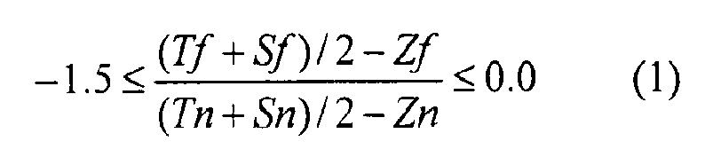
- each of the terms (Tf + Sf)/2 and (Tn + Sn)/2 in the conditional expression (1) means a mean value of the field curvature in the tangential direction and the field curvature in the sagittal direction.
- the amount of the field curvature at 80% image height is taken.
- spherical aberration of an imaging optical system of an endoscope tends to monotonically increase on the under side or the over side in accordance with an increase in aperture. Since the fine image position is based on rays transmitted through about 70% of the pupil diameter (zonal), as a representative value, the amount of the zonal spherical aberration is taken.
- An imaging optical system is configured to prevent extreme deterioration of the image of the object on the near point side and the far point side in the range of the observable distance, without using a focus adjustment mechanism, by properly adjusting change of field curvature in the range of the observable distance.
- FIG. 1 An imaging optical system 1 is schematically illustrated in Fig. 1 .
- an object distance Po is set on an optical axis Z, and a position on which light (illustrated by a solid line) from the object distance Po is focused by the imaging optical system 1 is defined as an imaging position Pi.
- the limit of image that is acceptably sharp in a cone of the ray is defined as a least circle of confusion diameter ⁇ .
- a range from the imaging position Pi to a point (P+ or P- in Fig. 1 ) where the cone of the ray reaches the least circle of confusion diameter ⁇ is defined as a depth of focus d on the image side.
- the point Pis defined as a point separated at a distance of the depth of focus d from the imaging position Pi toward the imaging optical system 1
- the point P+ is defined as a point separated at a distance of the depth of focus d from the imaging position Pi toward the opposite side to the imaging optical system 1.
- a range of an object side space conjugate to the range from the point P-to the point P+ is defined as a depth of field.
- a conjugate point that is optically conjugate to the point P- is defined as a point Pf
- a conjugate point that is optically conjugate to the point P+ is defined as a point Pn.
- the range from the point Pf to the point Pn is defined as the depth of field
- the point Pf is defined as a far point which is the farthest limit
- the point Pn is defined as a near point which is the nearest limit.
- FIG. 2 shows aberration diagrams in an embodiment of an endoscope imaging optical system.
- spherical aberration diagram at the imaging position Pi when the object is disposed at the preset object distance Po spherical aberration diagram at the imaging position Pi when the object is disposed at the preset object distance Po
- astigmatism field curvature in the sagittal direction and field curvature in the tangential direction
- a diagram for superposing both of them the spherical aberration diagram and the astigmatism diagram
- spherical aberration diagram and astigmatism diagram at the imaging position Pi when the object is disposed at the near point there is illustrated, in order from the left side of the drawing, spherical aberration diagram and astigmatism diagram at the imaging position Pi when the object is disposed at the near point, and a diagram for superposing both of them normalized by the maximum value of the vertical axis.
- spherical aberration diagram and astigmatism diagram at the imaging position Pi when the object is disposed at the far point and a diagram for superposing both of them normalized by the maximum value of the vertical axis.
- the reference numerals 0.7 and 0.8 are noted on positions corresponding to 70% and 80% of the maximum value on the vertical axis.
- an exemplary embodiment of the invention is configured so that the aforementioned terms including the amount of the spherical aberration and the amount of the field curvature at each of the near point and the far point satisfy the conditional expression (1).
- the change of image plane in the range of the observable distance is appropriately distributed, and the amounts of change in the image plane in observation on the near point side and the far point side are made to be substantially the same, whereby extreme deterioration in the image is suppressed even when the object distance changes.
- the resultant value of the conditional expression (1) becomes equal to -1, but the allowable limit thereof may be about -1.5.
- the least circle of confusion diameter ⁇ used as described above means the limit of the image blur that is acceptably sharp.
- the range is determined in accordance with the following concept. It can be said, resolution of human eyes is about 1' in angle of sight, and thus the limit of resolution in sharpness can be defined as about 4' which is four times thereof.
- observation about an image is performed not by directly looking the image but by looking the image displayed on a display device such as a television monitor. Therefore, it is premised that the image is observed by such a display device.
- ⁇ d 1500 mm ⁇ tan 4 / 60 ⁇ 1.75 mm .
- a vertical size of the display region is set by about 210 mm.
- a value of permissible blur ⁇ d on the display screen is equal to about 0.0083 ( ⁇ 1.75/210) of the vertical size of the display region.
- the permissible blur on the image plane at the imaging position Pi of the imaging optical system 1 that is, the least circle of confusion diameter ⁇ is determined.
- resolution of the imaging optical system at this time is 60 lp/mm, that is, 120 TV lines in resolution of display devices such as a television monitor.
- the amount of change of the image plane at the time when the least circle of confusion diameter ⁇ is in the range of 2V/240 ⁇ ⁇ ⁇ 2V/160 should be considered.
- a display device such as a television monitor was assumed from the usage situation of the general endoscope, and the case where observation is performed at a distance of about 1.5 m or more from the display device was exemplarily described.
- values of depth of field are different.
- even when the object distance changes in the range of the observable distance it is possible to obtain a fine image without extreme deterioration.
- the conditional expression (1) when the object is disposed at the far point and the near point of depth of field, the conditional expression (1) is satisfied.
- the change of image plane in the range of the observable distance can be appropriately distributed, and the amounts of change in the image plane in observation on the near point side and the far point side can be made to be substantially the same. Accordingly, it is possible to obtain a fine image without extreme deterioration even when an object distance changes in the range of the observable distance in a state where a focus adjustment mechanism for focusing responsive to change of the object distance is not employed.
- an endoscope imaging apparatus has the imaging optical system.
- the apparatus considering the case where the image is observed by a general display device such as a monitor, the range of the least circle of confusion diameter is determined. Thus, even when the object distance changes, it is possible to observe a fine image without extreme deterioration in the image.
- FIG. 4 is a schematic configuration diagram showing an exemplary embodiment of an endoscope system to which the imaging optical system and the imaging apparatus according to an exemplary embodiment of the invention is applicable.
- the endoscope system shown in Fig. 4 includes an endoscope 100, a processor 120 that is connected to the endoscope 100 and performs various processes such as light source control or image process, and a display device 122 that displays an image taken by the imaging optical system 2 of the endoscope 100.
- the endoscope 100 mostly has an operating section 102, an insertion section 104 that is connected to the front end side of the operating section 102, and a universal code 106 that is extracted from the rear end side of the operating section 102 and is connected to the processor 120.
- the insertion section 104 is operative to be inserted into a patient's body, and a great part thereof is formed as an elastic portion 107.
- a bending portion 108 is connected, and to the front end of the bending portion 108, a front end portion 110 is sequentially connected.
- the imaging optical system 2 is disposed as described later.
- the bending portion 108 is provided to make the front end portion 110 face in a desirable direction, and thus is configured to be able to perform a bending operation by turning the bending scan knob 109 provided on the operating section 102.
- Fig. 5 is a sectional diagram showing a principal part of the front end portion 110 including an optical axis of the imaging optical system 2.
- an imaging optical system 2 of which the optical axis is disposed parallel to a lengthwise direction of the insertion section 104, an optical path changing prism 7 that is operative to bend an optical path on the image side of the imaging optical system 2 by 90 degrees, and an imaging device 8 that is bonded to the optical path changing prism 7 so that a light receiving surface thereof is parallel to the lengthwise direction of the insertion section 104.
- the imaging optical system 2, the optical path changing prism 7, and the imaging device 8 constitute the imaging apparatus 10, but the optical path changing prism 7 is not an essential element in the invention.
- the imaging device 8 is operative to convert an image formed by the imaging optical system 2 into an electric signal for being displayed on the display device 122.
- a solid-state imaging device such as a CCD (Charge Coupled Device) or a CMOS (Complementary Metal Oxide Semiconductor) can be employed.
- a direct view optical system is formed by the imaging device 8 disposed therein as shown in Fig. 5 .
- a treatment tool insertion channel 9 is formed, and enables disposition of a plurality of elements in the thin insertion section.
- the imaging device 8 has a cover glass for protecting the light receiving surface, but the cover glass included in the imaging device 8 is not shown in Fig. 5 .
- the imaging optical system 2 in Fig. 5 does not exactly represent a lens shape, and is schematically illustrated.
- the optical axis of the optical path form the imaging optical system 2 to the imaging device 8 is represented by a chain line.
- the imaging optical system 2 does not have a focus adjustment mechanism for focusing on the changed object distance, and lens groups thereof remain stationary.
- a position on which light from an object distance is focused by the imaging optical system 2 is defined as an imaging position and the farthest limit and the nearest limit of depth of field in the imaging optical system 2 are defined as a far point and a near point, respectively.
- Zf an amount of the spherical aberration of a ray transmitted through 70% of a pupil diameter
- Sf an amount of the field curvature in the sagittal direction at 80% of the maximum image height
- Tf an amount of the field curvature in tangential direction at 80% of the maximum image height
- the far point of depth of field is defined as a conjugate point of a point separated at a distance of the depth of focus d from the imaging position toward the imaging optical system 2.
- the near point of depth of field is defined as a conjugate point of a point separated at a distance of the depth of focus d from the imaging position toward the opposite side of the imaging optical system 2.
- the least circle of confusion diameter ⁇ is in the range of 2V/240 ⁇ ⁇ ⁇ 2V/160, where V is a size at the imaging position of an image displayed in the vertical direction (an arrow direction in Fig. 4 ) on the display device 122.
- V is a size at the imaging position of an image displayed in the vertical direction (an arrow direction in Fig. 4 ) on the display device 122.
- a display region of a general display device is horizontally long, for example, in a case where an imaging region has a rectangular shape and a horizontal size thereof and a vertical size thereof are different, the size corresponding to the shorter one is set as V.
- the imaging region has a circular shape, a diameter thereof is set as V.
- the imaging optical system and endoscope imaging apparatus Due to the configuration as described above, in the imaging optical system and endoscope imaging apparatus according to the embodiment, even when the focus adjustment mechanism for focusing responsive to change of the object distance is not employed, the amounts of change in the image plane in observation on the near point side and the far point side can be made to be substantially the same. Thus, it is possible to obtain a fine image without extreme deterioration even when an object distance changes in the range of the observable distance.
- Table 1 shows lens data of the imaging optical system according to Example 1, and Fig. 6 is a lens configuration diagram thereof.
- the imaging optical system according to Example 1 is configured to have five lenses L1 to L5 in four groups.
- an aperture diaphragm St and optical members PP and CG having a plane parallel plate shape such as a filter, a prism, and a cover glass disposed between the lens system and the imaging point P.
- the aperture diaphragm St shown in Fig. 6 does not illustrate a shape and a size thereof, but illustrates a position thereof on the optical axis Z.
- the illustration of the aperture diaphragm St and the optical members having a plane parallel plate shape is similarly applied to examples to be described later.
- vdj represents an Abbe number of the j-th optical element at the d-line. In Table 1, units of the radius of curvature and the on-axis surface spacing are mm.
- a direction in which the radius of curvature is convex toward the object side is defined as a positive direction
- a direction in which the radius of curvature is convex toward the image side is defined as a negative direction.
- the reference signs in Table 1 have the same meaning as the reference signs in examples to be described later.
- Table 2 shows lens data of the imaging optical system according to Example 2
- Fig. 7 is a lens configuration diagram thereof.
- the imaging optical system according to Example 2 is configured to have five lenses L1 to L5 in four groups.
- an aperture diaphragm St and optical members PP and CG having a plane parallel plate shape such as a filter, a prism, and a cover glass disposed between the lens system and the imaging point P.
- Table 3 shows lens data of the imaging optical system according to Example 3, and Fig. 8 is a lens configuration diagram thereof.
- the imaging optical system according to Example 3 is configured to have five lenses L1 to L5 in four groups.
- an aperture diaphragm St and optical members PP and CG having a plane parallel plate shape such as a filter, a prism, and a cover glass disposed between the lens system and the imaging point P.
- Table 4 shows lens data of the imaging optical system according to Example 4, and Fig. 9 is a lens configuration diagram thereof.
- the imaging optical system according to Example 4 is configured to have five lenses L1 to L5 in four groups.
- an aperture diaphragm St and optical members PP and CG having a plane parallel plate shape such as a filter, a prism, and a cover glass disposed between the lens system and the imaging point P.
- Table 5 shows lens data of the imaging optical system according to Example 5, and Fig. 10 is a lens configuration diagram thereof.
- the imaging optical system according to Example 5 is configured to have six lenses L1 to L6 in four groups.
- an aperture diaphragm St and optical members PF, PP, and CG having a plane parallel plate shape such as a filter, a prism, and a cover glass disposed between the lens system and the imaging point P.
- Table 6 shows lens data of the imaging optical system according to Example 6, and Fig. 11 is a lens configuration diagram thereof.
- the imaging optical system according to Example 6 is configured to have six lenses L1 to L6 in four groups.
- an aperture diaphragm St and optical members PF, PP, and CG having a plane parallel plate shape such as a filter, a prism, and a cover glass disposed between the lens system and the imaging point P.
- Table 7 shows lens data of the imaging optical system according to Example 7, and Fig. 12 is a lens configuration diagram thereof.
- the imaging optical system according to Example 7 is configured to have five lenses L1 to L5 in four groups.
- an aperture diaphragm St and optical members PP and CG having a plane parallel plate shape such as a filter, a prism, and a cover glass disposed between the lens system and the imaging point P.
- Tables 8 to 11 show values corresponding to various data and the conditional expression (1) in Examples 1 to 7 mentioned above. A part of the reference signs noted in Tables 8 to 11 correspond to the reference signs shown in Fig. 1 . In Fig. 1 , other than the reference signs mentioned above, there are shown a focal length f, a front focus Ff, a back focus Bf, a distance Xo from a front focus position to the object distance Po, and a distance Xi from the back focus position to the imaging position Pi.
- set object distance is a distance from an object side surface of the lens L1 to the predetermined object distance Po preset initially.
- V size is the size of V mentioned above
- set object distance means the case where the object is disposed on the set object distance, the case where the object is disposed on the near point, and the case where the object is disposed on the far point, respectively.
- object distance in the row of “near point” means an object distance at the time of observation on the near point side, that is, a distance from the object side surface of the lens L1 to the near point.
- object distance in the row of “far point” means an object distance at the time of observation on the far point side, that is, a distance from the object side surface of the lens L1 to the far point.
- spherical aberration is an amount of the spherical aberration Zn of a ray transmitted through 70% of the pupil diameter
- S field curvature is an amount of the field curvature in the sagittal direction Sn at 80% of the maximum image height
- T field curvature is an amount of the field curvature in the tangential direction Tn at 80% of the maximum image height
- S, T mean value is a mean value Mn of the amounts of field curvature in the two directions (the sagittal and tangential directions) calculated by the equation (Tn + Sn)/2
- difference is calculated by the equation Mn-Zn.
- the examples satisfy the conditional expression (1). In these examples, even when the object distance changes in the range of the observable distance, extreme deterioration in the image is not caused. Thus, it is possible to obtain a fine image.
- Figs. 13 to 19 show spherical aberration, astigmatism, distortion in the imaging optical system according to Examples 1 to 7, respectively.
- aberration diagrams there are shown aberrations at the d-line as a reference wavelength.
- the solid line represents a sagittal direction
- the wavy line represents aberrations of a tangential direction.
- the FNo. in the spherical aberration diagram represents a F number
- the ⁇ in the other aberration diagrams represents a half angle of view.
- aberrations are satisfactorily corrected.
- the aberration diagrams in Figs. 13 to 19 correspond to examples shown in Tables 8 to 11.
- the aberration diagrams of the upper part, the middle part, and the lower part in Fig. 13 written as "Example 1-1" correspond to the case where the object is disposed on the set object distance, the case where the object is disposed on the near point, and the case where the object is disposed on the far point, in the column written as "Example 1-1" in Table 8, respectively.
- the description just mentioned above is similarly applied to the other aberration diagrams.
- the least circle of confusion diameter is determined by resolution and an observable distance.
- the least circle of confusion diameter is determined from a pitch of the pixel arrangement of the imaging device.
- the V size in examples shown in Tables 8 to 11 is in the range of 1.0 to 1.8 mm. From this, when the V size is applied to the range of the least circle of confusion diameter ⁇ , that is, 2V/240 ⁇ ⁇ ⁇ 2V/160, the resultant value of the least circle of confusion diameter ⁇ is expressed by 0.0083 mm ⁇ ⁇ ⁇ 0.0225 mm.
- the least circle of confusion diameter ⁇ corresponds to a length of 4 to 10 pixels.
- Table 12 shows a ratio ⁇ /P of the least circle of confusion diameter ⁇ to pitch P at the time when the pixel pitch P is set by 2 ⁇ m or 1.8 ⁇ m, in examples shown in Tables 8 to 11. Since the ratio ⁇ /P shown in Table 12 has values in the range of 4.2 to 11.3, the range of the least circle of confusion diameter ⁇ is expressed in terms of the pixel pitch P of the imaging device as 4P ⁇ ⁇ ⁇ 10P. On the basis of this, depth of field may be determined.
- EXAMPLE 1 EXAMPLE 2 EXAMPLE 3 EX 1-1 EX 1-2 EX 1-3 EX 2-1 EX 2-2 EX 3-1 EX 3-2 EX 3-3 PITCH ( ⁇ m) P 2 2 2 2 2 2 1.8 1.8 1.8 RATIO ⁇ /P 7.5 11.3 11.3 11.3 6.3 9.4 9.4 EXAMPLE 4 EXAMPLE 5 EX 4-1 EX 4-2 EX 4-3 EX 5-1 EX 5-2 EX 5-3 PITCH ( ⁇ m) P 1.8 1.8 1.8 1.8 1.8 RATIO ⁇ /P 6.3 9.4 9.4 6.3 9.4 EXAMPLE 6 EXAMPLE 7 EX 6-1 EX 6-2 EX 6-3 EX 7-1 EX 7-2 EX 7-3 PITCH ( ⁇ m) P 1.8 1.8 1.8 2 2 2 RATIO ⁇ /P 6.3 9.4 9.4 4.2 6.3 6.3
- the invention has been described with reference to the embodiment and the examples, but the invention is not limited to the embodiment mentioned above, and may be modified to various forms.
- the values of a radius of curvature, an on-axis surface spacing, and a refractive index of the lens components are not limited to the values noted in the numerical examples, and can have the other values.
- a mean value of the field curvature in the sagittal direction and the field curvature in the tangential direction at 80% of the image height is used.
- a mean value of the field curvature in the sagittal direction and the field curvature in the tangential direction at 100% (the maximum image height) of the image height may be used.
- a mean value of the field curvature in the sagittal direction and the field curvature in the tangential direction at 50% of the image height may be used.
- the field curvature in the sagittal direction is equivalent to the field curvature in the tangential direction, and a mean value of those is used.
- the field curvature in the sagittal direction and the field curvature in the tangential direction to which weights having different ratios are applied may be employed.
- only any one of the field curvature in the sagittal direction and the field curvature in the tangential direction may be used.
Landscapes
- Physics & Mathematics (AREA)
- Astronomy & Astrophysics (AREA)
- General Physics & Mathematics (AREA)
- Optics & Photonics (AREA)
- Lenses (AREA)
- Instruments For Viewing The Inside Of Hollow Bodies (AREA)
- Endoscopes (AREA)
Abstract
Description
- This application is based on and claims priority under 35 U.S.C §119 from Japanese Patent Application No.
2007-251111, filed on September 27, 2007 - The present invention relates to an imaging optical system and an endoscope imaging apparatus, and more particularly to an imaging optical system disposed in a front end portion of an insertion section of an endoscope and an endoscope imaging apparatus having the imaging optical system and an imaging device converting an image formed by the imaging optical system into an electric signal for displaying the image on a display device.
- Generally, to observe an inside of a patient's body and perform a treatment in medical field and the like, endoscopes have been used. In a front end portion of an insertion section of such an endoscope, an imaging optical system such as an objective lens for taking an image in a body cavity is disposed. In recent years, as surgery under such an endoscope has spread, generally, an image formed by the imaging optical system is displayed on a display device such as a television monitor, and an operator observes the image displayed on a screen of the display device. Hence, in order for the operator to easily observe the image, it is preferred that the image should have a small field curvature, and thus there has been proposed an endoscope objective lens for well correcting field curvature.
- Meanwhile, observation targets in a body cavity mostly have a protrusion shape and a tubulous shape, but it is preferred to obtain a fine image even from such observation targets. In
JP-A-2001-194580 US 6,400,514 , there is disclosed an endoscope objective lens that includes three lens groups and can generate field curvature so as to make image quality of the peripheral portion of the screen better, in accordance with an observation target, while magnification keeps at a substantially constant level, by moving at least one lens group. - However, when an object distance and an imaging position corresponding thereto are set, the general optical system for well correcting field curvature has been designed to match a fine image position on the center of a screen with a fine image position on the peripheral portion of the screen by correcting the amount of field curvature. In such a design, change of field curvature caused by change of an object distance has been not considered. Practically, as the object distance changes, field curvature also changes. Thus, although field curvature is well corrected at the imaging position preset at the time of design, the best image positions may be different between the screen center and the screen periphery when the object exists at a position unallowable in the design. Consequently, in the general optical system for correcting field curvature, there has been concern that extreme deterioration is caused in the screen periphery by change of the object distance.
- In addition, most of imaging apparatuses such as a camera mostly have a focus adjustment mechanism for adjusting change of the imaging position caused by change of the object distance, but most of endoscope imaging apparatuses does not have such a focus adjustment mechanism. In a case where the focus adjustment mechanism is disposed in the endoscope imaging apparatus, the configuration thereof becomes complicated and space for the focus adjustment mechanism is needed, and thus there is concern about an increase in aperture of the front end portion of the endoscope imaging apparatus.
- An object of an illustrative, non-limiting embodiment of the invention is to provide an imaging optical system for endoscope capable of obtaining a fine image without extreme deterioration even when an object distance changes in a state where a focus adjustment mechanism is not employed, and an endoscope imaging apparatus having the imaging optical system.
- According to an aspect of the invention, an imaging optical system is disposed in a front end portion of an insertion section of an endoscope. In the imaging optical system, a position on which light from an object distance is focused by the imaging optical system is defined as an imaging position and the farthest limit and the nearest limit of depth of field in the imaging optical system are defined as a far point and a near point, respectively. In this case, at the imaging position at the time when the object is disposed at the far point, it is assumed that an amount of a spherical aberration of a ray transmitted through 70% of a pupil diameter is Zf, an amount of a field curvature in the sagittel direction at 80% of the maximum image height is Sf, and an amount of a field curvature in the tangential direction at 80% of the maximum image height is Tf. In addition, at the imaging position at the time when the object is disposed at the near point, it is also assumed that an amount of a spherical aberration caused of a ray transmitted through 70% of a pupil diameter is Zn, an amount of a field curvature in the sagittal direction at 80% of the maximum image height is Sn, and an amount of a field curvature in the tangential direction at 80% of the maximum image height is Tn. Then, the following conditional expression (1) is satisfied.

- The imaging optical system may not include a focus adjustment mechanism for focusing responsive to change of the object distance.
- In addition, according to another aspect of the invention, an endoscope imaging apparatus includes: the imaging optical system according to an aspect of the invention; and an imaging device converting an image formed by the imaging optical system into an electric signal for displaying the image on a display device. In the endoscope imaging apparatus, the least circle of confusion diameter δ at the time when an image on the display device is observed is in the range of 2V/240 ≤ δ ≤ 2V/160, where V is a size at the imaging position of an image displayed in a vertical direction on the display device. In addition, a depth of focus d on an image side of the imaging optical system is defined as d = δ×Fe by the least circle of confusion diameter δ and an effective F number Fe. In this case, the far point is a conjugate point of a point separated at a distance of the depth of focus d from the imaging position toward the imaging optical system. On the other hand, the near point is a conjugate point of a point separated at a distance of the depth of focus d from the imaging position toward the opposite side to the imaging optical system.
- The features of the invention will appear more fully upon consideration of the exemplary example of the invention, which are schematically set forth in the drawings, in which:
-
Fig. 1 is an explanatory diagram showing a concept of an exemplary embodiment of the invention; -
Fig. 2 is an exemplary aberration diagram of an imaging optical system of an endoscope; -
Fig. 3 is an explanatory diagram showing observation at a near point; -
Fig. 4 is a schematic configuration diagram showing an endoscope system according to an exemplary embodiment of the invention; -
Fig. 5 is a schematic sectional diagram showing a front end portion of an insertion section of the endoscope; -
Fig. 6 is a lens configuration diagram of an imaging optical system according to Example 1; -
Fig. 7 is a lens configuration diagram of an imaging optical system according to Example 2; -
Fig. 8 is a lens configuration diagram of an imaging optical system according to Example 3; -
Fig. 9 is a lens configuration diagram of an imaging optical system according to Example 4; -
Fig. 10 is a lens configuration diagram of an imaging optical system according to Example 5; -
Fig. 11 is a lens configuration diagram of an imaging optical system according to Example 6; -
Fig. 12 is a lens configuration diagram of an imaging optical system according to Example 7; -
Fig. 13 is a diagram showing aberrations of the imaging optical system according to Example 1; -
Fig. 14 is a diagram showing aberrations of the imaging optical system according to Example 2; -
Fig. 15 is a diagram showing aberrations of the imaging optical system according to Example 3; -
Fig. 16 is a diagram showing aberrations of the imaging optical system according to Example 4; -
Fig. 17 is a diagram showing aberrations of the imaging optical system according to Example 5; -
Fig. 18 is a diagram showing aberrations of the imaging optical system according to Example 6; and -
Fig. 19 is a diagram showing aberrations of the imaging optical system according to Example 7. - In this specification, depth of field is defined as a range of distance in which the object is clearly visible when focusing is performed on the object at a position, that is, a range of distance in which the object image is acceptably sharp. In the invention, depth of field is assumed as a range of observable distance.
- In addition, each of the terms (Tf + Sf)/2 and (Tn + Sn)/2 in the conditional expression (1) means a mean value of the field curvature in the tangential direction and the field curvature in the sagittal direction. Here, to make good image balance in the screen center and the screen periphery, the amount of the field curvature at 80% image height is taken.
- In addition, spherical aberration of an imaging optical system of an endoscope tends to monotonically increase on the under side or the over side in accordance with an increase in aperture. Since the fine image position is based on rays transmitted through about 70% of the pupil diameter (zonal), as a representative value, the amount of the zonal spherical aberration is taken.
- An imaging optical system according to an exemplary embodiment of the invention is configured to prevent extreme deterioration of the image of the object on the near point side and the far point side in the range of the observable distance, without using a focus adjustment mechanism, by properly adjusting change of field curvature in the range of the observable distance.
- Referring to
Figs. 1 to 3 , a concept of the invention will be described. First, referring toFig. 1 , a method of obtaining depth of field will be described. An imagingoptical system 1 is schematically illustrated inFig. 1 . As shown inFig. 1 , an object distance Po is set on an optical axis Z, and a position on which light (illustrated by a solid line) from the object distance Po is focused by the imagingoptical system 1 is defined as an imaging position Pi. - Light from the object distance Po is mostly concentrated on one point at the imaging position Pi, but as distanced from the imaging position Pi, the cone of the light flux increases and its image blurs. In this case, the limit of image that is acceptably sharp in a cone of the ray is defined as a least circle of confusion diameter δ. A range from the imaging position Pi to a point (P+ or P- in
Fig. 1 ) where the cone of the ray reaches the least circle of confusion diameter δ is defined as a depth of focus d on the image side. Here, the point Pis defined as a point separated at a distance of the depth of focus d from the imaging position Pi toward the imagingoptical system 1, and the point P+ is defined as a point separated at a distance of the depth of focus d from the imaging position Pi toward the opposite side to the imagingoptical system 1. In addition, the depth of focus d is defined as d = δ×Fe by the least circle of confusion diameter δ and an effective F number Fe when the light from the object distance Po is focused on the imaging position Pi. - Since the range within the depth of focus is a range of the image that is acceptably sharp in image space, a range of an object side space conjugate to the range from the point P-to the point P+ is defined as a depth of field. As shown in
Fig. 1 , a conjugate point that is optically conjugate to the point P- is defined as a point Pf, and a conjugate point that is optically conjugate to the point P+ is defined as a point Pn. Accordingly, the range from the point Pf to the point Pn is defined as the depth of field, the point Pf is defined as a far point which is the farthest limit, and the point Pn is defined as a near point which is the nearest limit. - Next, field curvature at the imaging position Pi at the time when the object is disposed at the far point or near point will be described.
Fig. 2 shows aberration diagrams in an embodiment of an endoscope imaging optical system. In the upper part ofFig. 2 , there is illustrated, in order from the left side of the drawing, spherical aberration diagram at the imaging position Pi when the object is disposed at the preset object distance Po, astigmatism (field curvature in the sagittal direction and field curvature in the tangential direction) diagram, and a diagram for superposing both of them (the spherical aberration diagram and the astigmatism diagram) normalized by the maximum value of the vertical axis. - Similarly, in the middle part of
Fig. 2 , there is illustrated, in order from the left side of the drawing, spherical aberration diagram and astigmatism diagram at the imaging position Pi when the object is disposed at the near point, and a diagram for superposing both of them normalized by the maximum value of the vertical axis. In addition, in the lower part ofFig. 2 , there is illustrated, in order from the left side of the drawing, spherical aberration diagram and astigmatism diagram at the imaging position Pi when the object is disposed at the far point, and a diagram for superposing both of them normalized by the maximum value of the vertical axis. In the diagram for superposing both of them shown inFig. 2 , the reference numerals 0.7 and 0.8 are noted on positions corresponding to 70% and 80% of the maximum value on the vertical axis. - Generally, in an endoscope objective lens, even if field curvature and astigmatism is well corrected with respect to the object distance previously set at the time of design, there is a tendency that the image plane becomes under on the near point side and becomes over on the far point side in accordance with change of the object distance in the range of the observable distance, while change of spherical aberration is small, as shown in
Fig. 2 - Accordingly, an exemplary embodiment of the invention is configured so that the aforementioned terms including the amount of the spherical aberration and the amount of the field curvature at each of the near point and the far point satisfy the conditional expression (1). Thus, the change of image plane in the range of the observable distance is appropriately distributed, and the amounts of change in the image plane in observation on the near point side and the far point side are made to be substantially the same, whereby extreme deterioration in the image is suppressed even when the object distance changes. In addition, when the amounts of change of the image plane are distributed to be the same on the near point side and far point side, the resultant value of the conditional expression (1) becomes equal to -1, but the allowable limit thereof may be about -1.5.
- Besides, considering usage situation of the endoscope, in observation on the near point side, it is considered that a front end of an
insertion section 104 of the endoscope diagonally faces to theinner wall 3 of the interior of the body as shown inFig. 3 . Accordingly, an allowable range of the image plane that becomes under increases when the object is disposed on the near point side. Thus, 0.0 is set as the upper limit so that the image plane does not become over the far point side. - In addition, the least circle of confusion diameter δ used as described above means the limit of the image blur that is acceptably sharp. However, in an exemplary embodiment of the invention, the range is determined in accordance with the following concept. It can be said, resolution of human eyes is about 1' in angle of sight, and thus the limit of resolution in sharpness can be defined as about 4' which is four times thereof. In addition, in the recent endoscope, generally, observation about an image is performed not by directly looking the image but by looking the image displayed on a display device such as a television monitor. Therefore, it is premised that the image is observed by such a display device.
- When a user observes the image at a distance of 1.5 m from the display device, the maximum permissible blur δd on the display screen in sharpness is expressed by

- From the display device widely used at the present time, a vertical size of the display region is set by about 210 mm. In this case, a value of permissible blur δd on the display screen is equal to about 0.0083 (≅ 1.75/210) of the vertical size of the display region.
- From the permissible blur δd on the display screen, the permissible blur on the image plane at the imaging position Pi of the imaging
optical system 1, that is, the least circle of confusion diameter δ is determined. Assuming that a size at the imaging position Pi of the image displayed in the vertical direction on the display device is V, the least circle of confusion diameter δ is expressed by
- In addition, since 210÷1.75 = 120 is satisfied, the least circle of confusion diameter δ is represented by the following expression.

- Specifically, resolution of the imaging optical system at this time is 60 lp/mm, that is, 120 TV lines in resolution of display devices such as a television monitor. Here, since a frequency of 1 MHz in a video signal is equal to 80 TV lines, considering a unit of 1 MHz, the least circle of confusion diameter δ is expressed by

and thus is equal to 2V divided by 3 MHz (240 TV lines). - In practical usage, it should be considered that observation is performed at a farther distance from the display device. In this case, a value of the permissible blur δd on the display screen increases more than the value mentioned above. Accordingly, in a case where observation is performed at a farther distance, 3 MHz is set to be lowered to 2 MHz, and 2V is divided by 2 MHz (160 TV lines), whereby the least circle of confusion diameter δ is represented by the following expression.

- As described above, considering practical usage situation of the endoscope, the amount of change of the image plane at the time when the least circle of confusion diameter δ is in the range of 2V/240 ≤ δ ≤ 2V/160 should be considered.
- In addition, in the description mentioned above, a display device such as a television monitor was assumed from the usage situation of the general endoscope, and the case where observation is performed at a distance of about 1.5 m or more from the display device was exemplarily described. Depending on kinds of the display devices and observation situation, values of depth of field are different. However, according to the aforementioned concept of the invention, it is possible to calculate the near point and the far point in accordance with each case. In addition, even when the object distance changes in the range of the observable distance, it is possible to obtain a fine image without extreme deterioration.
- According to an exemplary embodiment of an imaging optical system of the invention, when the object is disposed at the far point and the near point of depth of field, the conditional expression (1) is satisfied. Thus, the change of image plane in the range of the observable distance can be appropriately distributed, and the amounts of change in the image plane in observation on the near point side and the far point side can be made to be substantially the same. Accordingly, it is possible to obtain a fine image without extreme deterioration even when an object distance changes in the range of the observable distance in a state where a focus adjustment mechanism for focusing responsive to change of the object distance is not employed.
- In addition, an endoscope imaging apparatus according to an exemplary embodiment of the invention has the imaging optical system. In the apparatus, considering the case where the image is observed by a general display device such as a monitor, the range of the least circle of confusion diameter is determined. Thus, even when the object distance changes, it is possible to observe a fine image without extreme deterioration in the image.
- Hereinafter, exemplary embodiments of the invention will be described in detail with reference to the drawings.
Fig. 4 is a schematic configuration diagram showing an exemplary embodiment of an endoscope system to which the imaging optical system and the imaging apparatus according to an exemplary embodiment of the invention is applicable. - The endoscope system shown in
Fig. 4 includes anendoscope 100, aprocessor 120 that is connected to theendoscope 100 and performs various processes such as light source control or image process, and adisplay device 122 that displays an image taken by the imagingoptical system 2 of theendoscope 100. - The
endoscope 100 mostly has anoperating section 102, aninsertion section 104 that is connected to the front end side of theoperating section 102, and auniversal code 106 that is extracted from the rear end side of theoperating section 102 and is connected to theprocessor 120. - The
insertion section 104 is operative to be inserted into a patient's body, and a great part thereof is formed as anelastic portion 107. To the front end of theelastic portion 107, a bendingportion 108 is connected, and to the front end of the bendingportion 108, afront end portion 110 is sequentially connected. In thefront end portion 110, the imagingoptical system 2 is disposed as described later. The bendingportion 108 is provided to make thefront end portion 110 face in a desirable direction, and thus is configured to be able to perform a bending operation by turning the bendingscan knob 109 provided on theoperating section 102. - Next, a schematic configuration of the
front end portion 110 in which the imagingoptical system 2 according to the embodiment is disposed will be described with reference toFig. 5. Fig. 5 is a sectional diagram showing a principal part of thefront end portion 110 including an optical axis of the imagingoptical system 2. - As shown in
Fig. 5 , in thefront end portion 110, there are provided an imagingoptical system 2 of which the optical axis is disposed parallel to a lengthwise direction of theinsertion section 104, an opticalpath changing prism 7 that is operative to bend an optical path on the image side of the imagingoptical system 2 by 90 degrees, and animaging device 8 that is bonded to the opticalpath changing prism 7 so that a light receiving surface thereof is parallel to the lengthwise direction of theinsertion section 104. In the embodiment, the imagingoptical system 2, the opticalpath changing prism 7, and theimaging device 8 constitute theimaging apparatus 10, but the opticalpath changing prism 7 is not an essential element in the invention. - The
imaging device 8 is operative to convert an image formed by the imagingoptical system 2 into an electric signal for being displayed on thedisplay device 122. As theimaging device 8, a solid-state imaging device such as a CCD (Charge Coupled Device) or a CMOS (Complementary Metal Oxide Semiconductor) can be employed. - In the lower half part of the
front end portion 110 shown inFig. 5 , a direct view optical system is formed by theimaging device 8 disposed therein as shown inFig. 5 . In addition, in the upper half part of thefront end portion 110 shown inFig. 5 , a treatmenttool insertion channel 9 is formed, and enables disposition of a plurality of elements in the thin insertion section. - In addition, the
imaging device 8 has a cover glass for protecting the light receiving surface, but the cover glass included in theimaging device 8 is not shown inFig. 5 . In addition, the imagingoptical system 2 inFig. 5 does not exactly represent a lens shape, and is schematically illustrated. InFig. 5 , the optical axis of the optical path form the imagingoptical system 2 to theimaging device 8 is represented by a chain line. - The imaging
optical system 2 according to the embodiment does not have a focus adjustment mechanism for focusing on the changed object distance, and lens groups thereof remain stationary. - In addition, in the imaging
optical system 2, a position on which light from an object distance is focused by the imagingoptical system 2 is defined as an imaging position and the farthest limit and the nearest limit of depth of field in the imagingoptical system 2 are defined as a far point and a near point, respectively. In this case, at the imaging position at the time when the object is disposed at the far point, it is assumed that an amount of the spherical aberration of a ray transmitted through 70% of a pupil diameter is Zf, an amount of the field curvature in the sagittal direction at 80% of the maximum image height is Sf, and an amount of the field curvature in tangential direction at 80% of the maximum image height is Tf. In addition, at the imaging position at the time when the object is disposed at the near point, it is also assumed that an amount of the spherical aberration of a ray transmitted through 70% of a pupil diameter is Zn, an amount of the field curvature in the sagittal direction at 80% of the maximum image height is Sn, and an amount of the field curvature in the tangential direction at 80% of the maximum image height is Tn. Then, the following conditional expression (1) is satisfied.
- In this case, the far point of depth of field is defined as a conjugate point of a point separated at a distance of the depth of focus d from the imaging position toward the imaging
optical system 2. On the other hand, the near point of depth of field is defined as a conjugate point of a point separated at a distance of the depth of focus d from the imaging position toward the opposite side of the imagingoptical system 2. The depth of focus d is defined as d = δ×Fe by the least circle of confusion diameter δ at the time when the image is observed by using thedisplay device 122 and an effective F number Fe at the time when the object distance and the imaging position are determined. - It is assumed that the least circle of confusion diameter δ is in the range of 2V/240 ≤ δ ≤ 2V/160, where V is a size at the imaging position of an image displayed in the vertical direction (an arrow direction in
Fig. 4 ) on thedisplay device 122. The reason why the aforementioned range is defined is described in the section of means for solving the problems. - In addition, since a display region of a general display device is horizontally long, for example, in a case where an imaging region has a rectangular shape and a horizontal size thereof and a vertical size thereof are different, the size corresponding to the shorter one is set as V. Alternatively, in a case where the imaging region has a circular shape, a diameter thereof is set as V.
- Due to the configuration as described above, in the imaging optical system and endoscope imaging apparatus according to the embodiment, even when the focus adjustment mechanism for focusing responsive to change of the object distance is not employed, the amounts of change in the image plane in observation on the near point side and the far point side can be made to be substantially the same. Thus, it is possible to obtain a fine image without extreme deterioration even when an object distance changes in the range of the observable distance.
- Hereinafter, numerical examples of the imaging optical system according to the invention will be described in detail.
- Table 1 shows lens data of the imaging optical system according to Example 1, and
Fig. 6 is a lens configuration diagram thereof. InFig. 6 , the reference signs Ri and Di (i = 1, 2, 3 ...) correspond to the Ri and the Di in Table 1. The imaging optical system according to Example 1 is configured to have five lenses L1 to L5 in four groups. In addition, in the lens data in Table 1 and the configuration diagram inFig. 6 , there are also shown an aperture diaphragm St and optical members PP and CG having a plane parallel plate shape such as a filter, a prism, and a cover glass disposed between the lens system and the imaging point P. In addition, the aperture diaphragm St shown inFig. 6 does not illustrate a shape and a size thereof, but illustrates a position thereof on the optical axis Z. In addition, the illustration of the aperture diaphragm St and the optical members having a plane parallel plate shape is similarly applied to examples to be described later. - In the lens data of Table 1, a surface number represents the sequential number of i-th (i = 1, 2, 3 ···) surface that sequentially increases as it gets closer to the image side when a surface of a component closest to the object side is defined as a first surface. In Table 1, Ri represents a radius of curvature of i-th (i = 1, 2, 3 ···) surface, and Di represents an on-axis surface spacing on the optical axis Z between the i-th (i = 1, 2, 3 ···) surface and the (i+1)th surface on the optical. In addition, Ndj represents a refractive index at the d-line (a wavelength of 587.6 nm) in a j-th (j = 1, 2, 3 ···) optical element of which the sequential number sequentially increases as it gets closer to the image side when a surface of the optical element closest to the object side is defined as a first surface. In addition, vdj represents an Abbe number of the j-th optical element at the d-line. In Table 1, units of the radius of curvature and the on-axis surface spacing are mm. In addition, a direction in which the radius of curvature is convex toward the object side is defined as a positive direction, and a direction in which the radius of curvature is convex toward the image side is defined as a negative direction. In addition, the reference signs in Table 1 have the same meaning as the reference signs in examples to be described later.
Table 1 Example 1 SURFACE NUMBER Ri Di Ndj νdj 1 ∞ 0.400 1.88300 40.8 2 0.832 0.370 3 7.468 1.460 1.84666 23.8 4 ∞ 0.000 5 (APERTURE DIAPHRAGM) ∞ 0.035 6 8.414 1.150 1.62041 60.3 7 -1.538 0.100 8 4.003 1.030 1.62041 60.3 9 -1.212 0.400 1.84666 23.8 10 -3.581 0.530 11 ∞ 2.800 1.55920 53.9 12 ∞ 0.300 1.51633 64.1 13 (IMAGE PLANE) ∞ - Table 2 shows lens data of the imaging optical system according to Example 2, and
Fig. 7 is a lens configuration diagram thereof. InFig. 7 , the reference signs Ri and Di (i = 1, 2, 3 ...) correspond to the Ri and the Di in Table 2. The imaging optical system according to Example 2 is configured to have five lenses L1 to L5 in four groups. In addition, in the lens data in Table 2 and the configuration diagram inFig. 7 , there are also shown an aperture diaphragm St and optical members PP and CG having a plane parallel plate shape such as a filter, a prism, and a cover glass disposed between the lens system and the imaging point P.Table 2 Example 2 SURFACE NUMBER Ri Di Ndj νdj 1 ∞ 0.400 1.88300 40.8 2 0.832 0.420 3 10.216 1.490 1.84666 23.8 4 ∞ 0.000 5 (APERTURE DIAPHRAGM) ∞ 0.035 6 10.589 1.050 1.62041 60.3 7 -1.818 0.100 8 5.437 1.050 1.62041 60.3 9 -0.953 0.400 1.84666 23.8 10 -1.901 0.570 11 ∞ 2.800 1.55920 53.9 12 ∞ 0.300 1.51633 64.1 13 (IMAGE PLANE) ∞ - Table 3 shows lens data of the imaging optical system according to Example 3, and
Fig. 8 is a lens configuration diagram thereof. InFig. 8 , the reference signs Ri and Di (i = 1, 2, 3 ···) correspond to the Ri and the Di in Table 3. The imaging optical system according to Example 3 is configured to have five lenses L1 to L5 in four groups. In addition, in the lens data in Table 3 and the configuration diagram inFig. 8 , there are also shown an aperture diaphragm St and optical members PP and CG having a plane parallel plate shape such as a filter, a prism, and a cover glass disposed between the lens system and the imaging point P.Table 3 Example 3 SURFACE NUMBER Ri Di Ndj νdj 1 ∞ 0.350 1.88300 40.8 2 0.703 0.331 3 4.165 0.980 1.92286 18.9 4 ∞ 0.000 5 (APERTURE DIAPHRAGM) ∞ 0.085 6 -3.647 0.890 1.71300 53.9 7 -1.175 0.100 8 3.191 0.910 1.62041 60.3 9 -1.125 0.350 1.92286 18.9 10 -2.277 0.372 11 ∞ 2.200 1.55920 53.9 12 ∞ 0.300 1.51633 64.1 13 (IMAGE PLANE) ∞ - Table 4 shows lens data of the imaging optical system according to Example 4, and
Fig. 9 is a lens configuration diagram thereof. InFig. 9 , the reference signs Ri and Di (i = 1, 2, 3 ···) correspond to the Ri and the Di in Table 4. The imaging optical system according to Example 4 is configured to have five lenses L1 to L5 in four groups. In addition, in the lens data in Table 4 and the configuration diagram inFig. 9 , there are also shown an aperture diaphragm St and optical members PP and CG having a plane parallel plate shape such as a filter, a prism, and a cover glass disposed between the lens system and the imaging point P.Table 4 Example 4 SURFACE NUMBER Ri Di Ndj νdj 1 ∞ 0.350 1.88300 40.8 2 0.703 0.441 3 7.135 1.070 1.92286 18.9 4 ∞ 0.000 5 (APERTURE DIAPHRAGM) DIAPHRAG M 0.085 6 -3.647 0.730 1.71300 53.9 7 -1.212 0.100 8 5.048 0.910 1.62041 60.3 9 -0.778 0.350 1.92286 18.9 10 -1.382 0.396 11 ∞ 2.200 1.55920 53.9 12 ∞ 0.300 1.51633 64.1 13 (IMAGE PLANE) ∞ - Table 5 shows lens data of the imaging optical system according to Example 5, and
Fig. 10 is a lens configuration diagram thereof. InFig. 10 , the reference signs Ri and Di (i = 1, 2, 3 ...) correspond to the Ri and the Di in Table 5. The imaging optical system according to Example 5 is configured to have six lenses L1 to L6 in four groups. In addition, in the lens data in Table 5 and the configuration diagram inFig. 10 , there are also shown an aperture diaphragm St and optical members PF, PP, and CG having a plane parallel plate shape such as a filter, a prism, and a cover glass disposed between the lens system and the imaging point P.Table 5 Example 5 SURFACE NUMBER Ri Di Ndj νdj 1 ∞ 0.350 1.88300 40.8 2 0.703 0.404 3 8.985 0.300 1.80400 46.6 4 1.471 0.850 1.84666 23.8 5 ∞ 0.000 6 (APERTURE DIAPHRAGM) ∞ 0.035 7 ∞ 0.790 1.62041 60.3 8 -1.25 0.100 9 6.723 0.900 1.62041 60.3 10 -0.892 0.360 1.92286 18.9 11 -1.661 0.361 12 ∞ 0.380 1.51633 64.1 13 ∞ 0.035 14 ∞ 2.200 1.55920 53.9 15 ∞ 0.300 1.51633 64.1 16 (IMAGE PLANE) ∞ - Table 6 shows lens data of the imaging optical system according to Example 6, and
Fig. 11 is a lens configuration diagram thereof. InFig. 11 , the reference signs Ri and Di (i = 1,2,3 ...) correspond to the Ri and the Di in Table 6. The imaging optical system according to Example 6 is configured to have six lenses L1 to L6 in four groups. In addition, in the lens data in Table 6 and the configuration diagram inFig. 11 , there are also shown an aperture diaphragm St and optical members PF, PP, and CG having a plane parallel plate shape such as a filter, a prism, and a cover glass disposed between the lens system and the imaging point P.Table 6 Example 6 SURFACE NUMBER Ri Di Ndj νdj 1 ∞ 0.350 1.88300 40.8 2 0.778 0.545 3 ∞ 0.350 1.83481 42.7 4 0.953 0.890 1.84666 23.8 5 9.553 0.016 6 (APERTURE DIAPHRAGM) ∞ 0.035 7 ∞ 0.980 1.62041 60.3 8 -1.304 0.100 9 5.675 0.890 1.62041 60.3 10 -0.892 0.360 1.92286 18.9 11 -1.594 0.379 12 ∞ 0.380 1.51633 64.1 13 ∞ 0.035 14 ∞ 2.200 1.55920 53.6 15 ∞ 0.300 1.51633 64.1 16 (IMAGE PLANE) ∞ - Table 7 shows lens data of the imaging optical system according to Example 7, and
Fig. 12 is a lens configuration diagram thereof. InFig. 12 , the reference signs Ri and Di (i = 1, 2, 3 ···) correspond to the Ri and the Di in Table 7. The imaging optical system according to Example 7 is configured to have five lenses L1 to L5 in four groups. In addition, in the lens data in Table 7 and the configuration diagram inFig. 12 , there are also shown an aperture diaphragm St and optical members PP and CG having a plane parallel plate shape such as a filter, a prism, and a cover glass disposed between the lens system and the imaging point P.Table 7 Example 7 SURFACE NUMBER Ri Di Ndj νdj 1 ∞ 0.250 1.88300 40.8 2 0.5 0.500 3 ∞ 0.920 1.92286 18.9 4 ∞ 0.000 5 (APERTURE DIAPHRAGM) ∞ 0.035 6 ∞ 0.650 1.71300 53.9 7 -1.426 0.260 8 1.901 0.810 1.62041 60.3 9 -0.644 0.350 1.92286 18.9 10 -1.304 0.371 11 ∞ 1.700 1.55920 53.9 12 ∞ 0.250 1.51633 64.1 13 (IMAGE PLANE) ∞ - Tables 8 to 11 show values corresponding to various data and the conditional expression (1) in Examples 1 to 7 mentioned above. A part of the reference signs noted in Tables 8 to 11 correspond to the reference signs shown in
Fig. 1 . InFig. 1 , other than the reference signs mentioned above, there are shown a focal length f, a front focus Ff, a back focus Bf, a distance Xo from a front focus position to the object distance Po, and a distance Xi from the back focus position to the imaging position Pi. - In Tables 8 to 11, "set object distance" is a distance from an object side surface of the lens L1 to the predetermined object distance Po preset initially. In addition, "V size" is the size of V mentioned above, and "TV lines" is a value used to determine the least circle of confusion diameter δ represented by the expression: the least circle of confusion diameter δ = 2V/(the number of TV lines).
- In addition, "set object distance" "near point", and "far point" noted on the left end column in each table mean the case where the object is disposed on the set object distance, the case where the object is disposed on the near point, and the case where the object is disposed on the far point, respectively. For example, "object distance" in the row of "near point" means an object distance at the time of observation on the near point side, that is, a distance from the object side surface of the lens L1 to the near point. Likewise, "object distance" in the row of "far point" means an object distance at the time of observation on the far point side, that is, a distance from the object side surface of the lens L1 to the far point.
- Explaining the low of the near point as an example, "spherical aberration" is an amount of the spherical aberration Zn of a ray transmitted through 70% of the pupil diameter, "S field curvature" is an amount of the field curvature in the sagittal direction Sn at 80% of the maximum image height, "T field curvature" is an amount of the field curvature in the tangential direction Tn at 80% of the maximum image height, and "S, T mean value" is a mean value Mn of the amounts of field curvature in the two directions (the sagittal and tangential directions) calculated by the equation (Tn + Sn)/2, and "difference" is calculated by the equation Mn-Zn. The description just mentioned above is also similarly applied to the rows of the set object distance and the far point.
- In Tables 8 to 11, with respect to Example 1, 3, 4, 5, and 6, the TV lines and the set object distance are defined as variables, and with respect to Example 2, the set object distance is defined as a variable.
Table 8 EXAMPLE 1 EXAMPLE 2 EX 1-1 EX 1-2 EX 1-3 EX 1-2 EX 2-2 IMAGE HEIGHT (mm) Y 1.20 1.20 1.20 1.00 1.00 FOCAL LENGTH (mm) f 1.2057 1.2057 1.2057 1.0293 1.0293 FRONT FOCUS (mm) Ff 0.4770 0.4770 0.4770 0.5988 0.5988 TOTAL ANGLE OF VIEW (DEGREES) 2ω 134.8 134.8 133.3 131.1 129.9 APERTURE DIAPHRAGM (mm) φ 0.40 0.40 0.40 0.35 0.35 DIAMETER SET OBJECT DISTANCE (mm) 10.0 10.0 8.0 8.0 6.0 EFFECTIVE F NUMBER Fe 6.641 6.641 6.682 6.617 6.653 V SIZE (mm) V 1.80 1.80 1.80 1.80 1.80 TV LINES (LINES) 240 160 160 160 160 THE LEAST CIRCLE OF CONFUSION DIAMETER (mm) δ 0.0150 0.0225 0.0225 0.0225 0.0225 DEPTH OF FOCUS (mm) d 0.0996 0.1494 0.1503 0.1489 0.1497 SET OBJECT DISTANCE OBJECT DISTANCE (mm) 10.0 10.0 8.0 8.0 6.0 IMAGE DISTANCE (mm) Xi 0.1388 0.1388 0.1715 0.1232 0.1605 SPHERICAL ABERRATION (µm) Z -4.4 -4.4 -4.5 -2.3 -2.5 S FIELD CURVATURE (µm) S -8.3 -8.3 -17.1 -26.2 -35.4 T FIELD CURVATURE (µm) T -37.9 -37.9 -58.3 -74.9 -96.7 S, T MEAN VALUE (µm) M -23.1 -23.1 -37.7 -50.6 -66.0 DIFFERENCE (µm) M-Z -18.7 -18.7 -33.2 -48.3 -63.5 NEAR POINT OBJECT DISTANCE (mm) Dnear 5.62 4.57 4.04 3.29 2.82 SPHERICAL ABERRATION (µm) Zn -4.8 -5.0 -5.2 -3.1 -3.4 S FIELD CURVATURE (µm) Sn -33.9 -45.3 -52.5 -59.5 -66.5 T FIELD CURVATURE (µm) Tn -98.1 -125.9 -144.1 -158.8 -175.2 S, T MEAN VALUE (µm) Mn -66.0 -85.6 -98.3 -109.2 -120.8 DIFFERENCE (µm) Mn-Zn -61.1 -80.6 -93.2 -106.0 -117.5 FAR POINT OBJECT DISTANCE (mm) Dfar 36.7 ∞ 68.3 ∞ 97.1 SPHERICAL ABERRATION (µm) Zf -4.0 -3.8 -3.9 -1.6 -1.7 S FIELD CURVATURE (µm) Sf 21.1 33.8 26.9 8.2 4.9 T FIELD CURVATURE (µm) Tf 27.9 55.3 40.4 2.8 -4.4 S, T MEAN VALUE (µm) Mf 24.5 44.6 33.6 5.5 0.3 DIFFERENCE (µm) Mf-Zf 28.5 48.4 37.5 7.1 2.0 
-0.47 -0.60 -0.40 -0.07 -0.02 Table 9 EXAMPLE 3 EXAMPLE 4 EX 3-1 EX 3-2 EX 3-3 EX 4-1 EX 4-2 EX 4-3 IMAGE HEIGHT (mm) Y 0.90 0.90 0.90 0.75 0.75 0.75 FOCAL LENGTH (mm) f 0.9223 0.9223 0.9223 0.7650 0.7650 0.7650 FRONT FOCUS (mm) Ff 0.4517 0.4517 0.4517 0.5467 0.5467 0.5467 TOTAL ANGLE OF VIEW (DEGREES) 2ω 134.9 134.9 134 137.1 137.1 136.6 APERTURE DIAPHRAGM DIAMETER (mm) φ 0.35 0.35 0.35 0.35 0.35 0.45 SET OBJECT DISTANCE (mm) 10.0 10.0 8.0 10.0 10.0 8.0 EFFECTIVE F NUMBER Fe 5.177 5.177 5.177 4.807 4.807 3.75 V SIZE (mm) V 1.35 1.35 1.35 1.35 1.35 1.35 TV LINES (LINES) 240 160 160 240 160 160 THE LEAST CIRCLE OF CONFUSION DIAMETER (mm) δ 0.0113 0.0169 0.0169 0.0113 0.0169 0.0169 DEPTH OF FOCUS (mm) d 0.0582 0.0874 0.0874 0.0541 0.0811 0.0633 SET OBJECT DISTANCE OBJECT DISTANCE (mm) 10.0 10.0 8.0 10.0 10.0 8.0 IMAGE DISTANCE (mm) Xi 0.08 14 0.08 14 0.1007 0.0555 0.0555 0.0685 SPHERICAL ABERRATION (µm) Z -10.6 -10.6 -10.7 -12.4 -12.4 -20.4 S FIELD CURVATURE (µm) S -0.9 -0.9 -5.4 -6.5 -6.5 -10.2 T FIELD CURVATURE (µm) T -22.5 -22.5 -34.8 -32.4 -32.4 -40.7 S, T MEAN VALUE (µm) M -11.7 -11.7 -20.1 -19.4 -19.4 -25.4 DIFFERENCE (µm) M-Z -1.1 -1.1 -9.4 -7.0 -7.0 -5.1 NEAR POINT OBJECT DISTANCE (mm) Dnear 5.64 4.59 4.07 4.79 3.74 3.90 SPHERICAL ABERRATION (µm) Zn -11.0 -11.2 -11.4 -13.0 -13.3 -13.7 S FIELD CURVATURE (µm) Sn -15.8 -23.1 -27.8 -21.1 -27.8 -26.6 T FIELD CURVATURE (µm) Tn -58.8 -76.2 -87.4 -66.1 -82.0 -79.2 S, T MEAN VALUE (µm) Mn -37.3 -49.6 -57.6 -43.6 -54.9 -52.9 DIFFERENCE (µm) Mn-Zn -26.3 -38.4 -46.2 -30.7 -41.6 -39.2 FAR POINT OBJECT DISTANCE (mm) Dfar 36.3 ∞ 63.5 413.0 ∞ 112.0 SPHERICAL ABERRATION (µm) Zf -10.2 -10.0 -10.1 -11.9 -11.9 -12.3 S FIELD CURVATURE (µm) Sf 17.4 24.7 20.4 9.9 10.4 8.7 T FIELD CURVATURE (µm) Tf 16.0 31.8 22.7 3.6 4.6 1.0 S, T MEAN VALUE (µm) Mf 16.7 28.3 21.6 6.8 7.5 4.9 DIFFERENCE (µm) Mf-Zf 26.8 38.3 31.7 18.7 19.4 17.2 
-1.02 -1.00 -0.68 -0.61 -0.47 -0.44 Table 10 EXAMPLE 5 EXAMPLE 6 EX 5-1 EX 5-2 EX 5-3 EX 6-1 EX 6-2 EX 6-3 IMAGE HEIGHT (mm) Y 0.90 0.90 0.90 0.75 0.75 0.75 FOCAL LENGTH (mm) f 0.9137 0.9137 0.9137 0.7626 0.7626 0.7626 FRONT FOCUS (mm) Ff 0.4894 0.4894 0.4894 0.6172 0.6172 0.6172 TOTAL ANGLE OF VIEW (DEGREES) 2ω 134.8 134.8 134.8 137.8 137.8 137.5 APERTURE DIAPHRAGM DIAMETER (mm) φ 0.40 0.40 0.40 0.40 0.40 0.45 SET OBJECT DISTANCE (mm) 10.0 10.0 8.0 8.0 8.0 7.0 EFFECTIVE F NUMBER Fe 5.17 5.17 5.188 4.695 4.695 4.179 V SIZE (mm) V 1.35 1.35 1.35 1.35 1.35 1.35 TV LINES (LINES) 240 160 160 240 160 160 THE LEAST CIRCLE OF CONFUSION DIAMETER (mm) δ 0.0113 0.0169 0.0169 0.0113 0.0169 0.0169 DEPTH OF FOCUS (mm) d 0.0582 0.0872 0.0875 0.0528 0.0792 0.0705 SET OBJECT DISTANCE OBJECT DISTANCE (mm) 10.0 10.0 8.0 8.0 8.0 7.0 IMAGE DISTANCE (mm) Xi 0.0796 0.0796 0.0983 0.0675 0.0675 0.0764 SPHERICAL ABERRATION (µm) Z -12.3 -12.3 -12.4 -16.8 -16.8 -21.2 S FIELD CURVATURE (µm) S -0.7 -0.7 -5.8 -2.1 -2.1 -4.5 T FIELD CURVATURE (µm) T -20.6 -20.6 -32.3 -26.9 -26.9 -32.5 S, T MEAN VALUE (µm) M -10.7 -10.7 -19.1 -14.5 -14.5 -18.5 DIFFERENCE (µm) M-Z 1.6 1.6 -6.7 -10.1 -10.1 -11.3 NEAR POINT OBJECT DISTANCE (mm) Dnear 5.57 4.51 4.00 4.22 3.35 3.34 SPHERICAL ABERRATION (µm) Zn -12.8 -13.1 -13.3 -17.3 -17.6 -18.3 S FIELD CURVATURE (µm) Sn -16.0 -23.1 -27.5 -15.9 -22.2 -22.2 T FIELD CURVATURE (µm) Tn -56.2 -73.1 -83.8 -59.3 -74.6 -74.8 S, T MEAN VALUE (µm) Mn -36.1 -48.1 -55.6 -37.6 -48.4 -48.5 DIFFERENCE (µm) Mn-Zn -23.3 -35.0 -42.4 -20.3 -30.8 -30.2 FAR POINT OBJECT DISTANCE (mm) Dfar 38.5 ∞ 76.9 39.0 ∞ 99.0 SPHERICAL ABERRATION (µm) Zf -11.7 -11.5 -11.6 -16.3 -16.2 -16.9 S FIELD CURVATURE (µm) Sf 16.2 22.9 19.5 13.6 18.3 16.4 T FIELD CURVATURE (µm) Tf 17.2 31.8 24.4 7.8 17.9 13.9 S, T MEAN VALUE (µm) Mf 16.7 27.3 22.0 10.7 18.1 15.1 DIFFERENCE (µm) Mf-Zf 28.4 38.8 33.6 27.0 34.2 32.0 
-1.22 -1.11 -0.79 -1.33 -1.11 -1.06 Table 11 EXAMPLE 7 EX 7-1 EX 7-2 EX 7-3 IMAGE HEIGHT (mm) Y 0.50 0.50 0.50 FOCAL LENGTH (mm) f 0.5473 0.5473 0.5473 FRONT FOCUS (mm) Ff 0.4431 0.4431 0.4431 TOTAL ANGLE OF VIEW (DEGREES) 2ω 124.5 124.5 124 APERTURE DIAPHRAGM DIAMETER (mm) φ 0.35 0.35 0.40 SET OBJECT DISTANCE (mm) 7.0 7.0 5.0 EFFECTIVE F NUMBER Fe 4.432 4.432 3.901 V SIZE (mm) V 1.00 1.00 1.00 TV LINES (LINES) 240 160 160 THE LEAST CIRCLE OF CONFUSION DIAMETER (mm) δ 0.0083 0.0125 0.0125 DEPTH OF FOCUS (mm) d 0.0369 0.0554 0.0488 SET OBJECT DISTANCE OBJECT DISTANCE (mm) 7.0 7.0 5.0 IMAGE DISTANCE (mm) Xi 0.0402 0.0402 0.0550 SPHERICAL ABERRATION (µm) Z 5.3 5.3 7.0 S FIELD CURVATURE (µm) S 2.4 2.4 -1.3 T FIELD CURVATURE (µm) T -21.1 -21.1 -29.8 S, T MEAN VALUE (µm) M -9.3 -9.3 -15.5 DIFFERENCE (µm) M-Z -26.4 -26.4 -36.8 NEAR POINT OBJECT DISTANCE (mm) Dnear 3.44 2.69 2.44 SPHERICAL ABERRATION (µm) Zn 3.7 3.6 3.5 S FIELD CURVATURE (µm) Sn -6.5 -10.6 -12.4 T FIELD CURVATURE (µm) Tn -42.4 -52.4 -56.8 S, T MEAN VALUE (µm) Mn -24.4 -31.5 -34.6 DIFFERENCE (µm) Mn-Zn -28.1 -35.1 -38.1 FAR POINT OBJECT DISTANCE (mm) Dfar 90.1 ∞ 47.4 SPHERICAL ABERRATION (µm) Zf 4.2 4.2 4.1 S FIELD CURVATURE (µm) Sf 12.4 13.4 11.6 T FIELD CURVATURE (µm) Tf 1.5 3.6 0.0 S, T MEAN VALUE (µm) Mf 7.0 8.5 5.8 DIFFERENCE (µm) Mf-Zf 2.8 4.3 1.7 
-0.10 -0.12 -0.04 - As known from the values corresponding to the expression (1) in Tables 8 to 11, the examples satisfy the conditional expression (1). In these examples, even when the object distance changes in the range of the observable distance, extreme deterioration in the image is not caused. Thus, it is possible to obtain a fine image.
-
Figs. 13 to 19 show spherical aberration, astigmatism, distortion in the imaging optical system according to Examples 1 to 7, respectively. In the aberration diagrams, there are shown aberrations at the d-line as a reference wavelength. In the astigmatism diagram, the solid line represents a sagittal direction, and the wavy line represents aberrations of a tangential direction. The FNo. in the spherical aberration diagram represents a F number, and the ω in the other aberration diagrams represents a half angle of view. As known fromFigs. 13 to 19 , in Examples 1 to 7, aberrations are satisfactorily corrected. - Here, the aberration diagrams in
Figs. 13 to 19 correspond to examples shown in Tables 8 to 11. For example, the aberration diagrams of the upper part, the middle part, and the lower part inFig. 13 written as "Example 1-1" correspond to the case where the object is disposed on the set object distance, the case where the object is disposed on the near point, and the case where the object is disposed on the far point, in the column written as "Example 1-1" in Table 8, respectively. The description just mentioned above is similarly applied to the other aberration diagrams. - In addition, in the embodiment mentioned above, the least circle of confusion diameter is determined by resolution and an observable distance. However, in an endoscope imaging apparatus in which an image is formed by an imaging device having a plurality of pixels arranged thereon, it can be considered that the least circle of confusion diameter is determined from a pitch of the pixel arrangement of the imaging device.
- For example, the V size in examples shown in Tables 8 to 11 is in the range of 1.0 to 1.8 mm. From this, when the V size is applied to the range of the least circle of confusion diameter δ, that is, 2V/240 ≤ δ ≤ 2V/160, the resultant value of the least circle of confusion diameter δ is expressed by 0.0083 mm ≤ δ ≤ 0.0225 mm. Here, when the pitch of the pixels in the imaging device is set by about 2 µm, the least circle of confusion diameter δ corresponds to a length of 4 to 10 pixels.
- Specifically, Table 12 shows a ratio δ/P of the least circle of confusion diameter δ to pitch P at the time when the pixel pitch P is set by 2 µm or 1.8 µm, in examples shown in Tables 8 to 11. Since the ratio δ/P shown in Table 12 has values in the range of 4.2 to 11.3, the range of the least circle of confusion diameter δ is expressed in terms of the pixel pitch P of the imaging device as 4P ≤ δ ≤ 10P. On the basis of this, depth of field may be determined.
Table 12 EXAMPLE 1 EXAMPLE 2 EXAMPLE 3 EX 1-1 EX 1-2 EX 1-3 EX 2-1 EX 2-2 EX 3-1 EX 3-2 EX 3-3 PITCH (µm) P 2 2 2 2 2 1.8 1.8 1.8 RATIO δ/P 7.5 11.3 11.3 11.3 11.3 6.3 9.4 9.4 EXAMPLE 4 EXAMPLE 5 EX 4-1 EX 4-2 EX 4-3 EX 5-1 EX 5-2 EX 5-3 PITCH (µm) P 1.8 1.8 1.8 1.8 1.8 1.8 RATIO δ/P 6.3 9.4 9.4 6.3 9.4 9.4 EXAMPLE 6 EXAMPLE 7 EX 6-1 EX 6-2 EX 6-3 EX 7-1 EX 7-2 EX 7-3 PITCH (µm) P 1.8 1.8 1.8 2 2 2 RATIO δ/P 6.3 9.4 9.4 4.2 6.3 6.3 - The invention has been described with reference to the embodiment and the examples, but the invention is not limited to the embodiment mentioned above, and may be modified to various forms. For example, the values of a radius of curvature, an on-axis surface spacing, and a refractive index of the lens components are not limited to the values noted in the numerical examples, and can have the other values.
- For example, in the embodiment, and a mean value of the field curvature in the sagittal direction and the field curvature in the tangential direction at 80% of the image height is used. However, in a case where even the most periphery of the screen is seriously considered, a mean value of the field curvature in the sagittal direction and the field curvature in the tangential direction at 100% (the maximum image height) of the image height may be used. Conversely, in a case where it is possible to obtain a fine image even at about 50% of the image height, a mean value of the field curvature in the sagittal direction and the field curvature in the tangential direction at 50% of the image height may be used.
- As described above, it is possible to optionally set what percent of the image height the amount of field curvature is used at, in accordance with specification of the required optical system. Likewise, even in spherical aberration, it is possible to properly set what percent of pupil diameter spherical aberration caused by a ray transmitted therethrough is used at, as occasion demands.
- In addition, in the embodiment, it is assumed that the field curvature in the sagittal direction is equivalent to the field curvature in the tangential direction, and a mean value of those is used. However, the field curvature in the sagittal direction and the field curvature in the tangential direction to which weights having different ratios are applied may be employed. In addition, as an extreme example, only any one of the field curvature in the sagittal direction and the field curvature in the tangential direction may be used.
Claims (4)
- An imaging optical system disposed in a front end portion of an insertion section of an endoscope,
wherein
when a position on which light from an object distance is focused by the imaging optical system is defined as an imaging position, and the farthest limit and the nearest limit of depth of field in the imaging optical system are defined as a far point and a near point, respectively, the imaging optical system satisfies conditional expression (1):
whereinZf represents a spherical aberration of a ray transmitted through 70% of a pupil diameter at the imaging position at a time when an object is disposed at the far point,Sf represents a field curvature in a sagittal direction at 80% of a maximum image height at the imaging position at the time when the object is disposed at the far point,Tf represents a field curvature in a tangential direction at 80% of the maximum image height at the imaging position at the time when the object is disposed at the far point,Zn represents a spherical aberration of a ray transmitted through 70% of a pupil diameter at the imaging position at a time when the object is disposed at the near point,Sn represents a field curvature in a sagittal direction at 80% of the maximum image height at the imaging position at the time when the object is disposed at the near point, andTf represents a field curvature in a tangential direction at 80% of the maximum image height at the imaging position at the time when the object is disposed at the near point. - The imaging optical system according to claim 1, which does not include a focus adjustment mechanism for focusing responsive to change of the object distance.
- An endoscope imaging apparatus comprising:an imaging optical system according to claim 1; andan imaging device that converts an image formed by the imaging optical system into an electric signal for displaying the image on a display device,whereinthe least circle of confusion diameter δ at a time when an image on the display device is observed satisfies 2V/240 ≤ δ ≤ 2V/160, wherein V represents a size at the imaging position of an image displayed in a vertical direction on the display device, andwhen a depth of focus d on an image side of the imaging optical system is defined as d = δ×Fe by the least circle of confusion diameter δ and an effective F number Fe,the far point is a conjugate point of a point separated at a distance of the depth of focus d from the imaging position toward the imaging optical system, andthe near point is a conjugate point of a point separated at a distance of the depth of focus d from the imaging position toward an opposite side to the imaging optical system.
- An endoscope imaging apparatus comprising:an imaging optical system according to claim 2; andan imaging device that converts an image formed by the imaging optical system into an electric signal for displaying the image on a display device,whereinthe least circle of confusion diameter δ at a time when an image on the display device is observed satisfies 2V/240 ≤ δ ≤ 2V/160, wherein V represents a size at the imaging position of an image displayed in a vertical direction on the display device, andwhen a depth of focus d on an image side of the imaging optical system is defined as d = δ×Fe by the least circle of confusion diameter δ and an effective F number Fe,the far point is a conjugate point of a point separated at a distance of the depth of focus d from the imaging position toward the imaging optical system, andthe near point is a conjugate point of a point separated at a distance of the depth of focus d from the imaging position toward an opposite side to the imaging optical system.
Applications Claiming Priority (1)
| Application Number | Priority Date | Filing Date | Title |
|---|---|---|---|
| JP2007251111A JP2009080413A (en) | 2007-09-27 | 2007-09-27 | Imaging optical system, image pickup apparatus for endoscope |
Publications (2)
| Publication Number | Publication Date |
|---|---|
| EP2042908A2 true EP2042908A2 (en) | 2009-04-01 |
| EP2042908A3 EP2042908A3 (en) | 2009-10-28 |
Family
ID=40220217
Family Applications (1)
| Application Number | Title | Priority Date | Filing Date |
|---|---|---|---|
| EP08016015A Withdrawn EP2042908A3 (en) | 2007-09-27 | 2008-09-11 | Imaging optical system and endoscope imaging apparatus |
Country Status (4)
| Country | Link |
|---|---|
| US (1) | US20090086017A1 (en) |
| EP (1) | EP2042908A3 (en) |
| JP (1) | JP2009080413A (en) |
| CN (1) | CN101396258A (en) |
Families Citing this family (88)
| Publication number | Priority date | Publication date | Assignee | Title |
|---|---|---|---|---|
| JP5324321B2 (en) * | 2009-05-29 | 2013-10-23 | 富士フイルム株式会社 | Endoscope objective lens and endoscope |
| US9474440B2 (en) | 2009-06-18 | 2016-10-25 | Endochoice, Inc. | Endoscope tip position visual indicator and heat management system |
| WO2012077116A1 (en) | 2010-12-09 | 2012-06-14 | Peermedical Ltd. | Flexible electronic circuit board for a multi-camera endoscope |
| US8926502B2 (en) | 2011-03-07 | 2015-01-06 | Endochoice, Inc. | Multi camera endoscope having a side service channel |
| US9492063B2 (en) | 2009-06-18 | 2016-11-15 | Endochoice Innovation Center Ltd. | Multi-viewing element endoscope |
| US9101268B2 (en) | 2009-06-18 | 2015-08-11 | Endochoice Innovation Center Ltd. | Multi-camera endoscope |
| US9101287B2 (en) | 2011-03-07 | 2015-08-11 | Endochoice Innovation Center Ltd. | Multi camera endoscope assembly having multiple working channels |
| US9706903B2 (en) | 2009-06-18 | 2017-07-18 | Endochoice, Inc. | Multiple viewing elements endoscope system with modular imaging units |
| US9872609B2 (en) | 2009-06-18 | 2018-01-23 | Endochoice Innovation Center Ltd. | Multi-camera endoscope |
| US11547275B2 (en) | 2009-06-18 | 2023-01-10 | Endochoice, Inc. | Compact multi-viewing element endoscope system |
| US9402533B2 (en) | 2011-03-07 | 2016-08-02 | Endochoice Innovation Center Ltd. | Endoscope circuit board assembly |
| US12137873B2 (en) | 2009-06-18 | 2024-11-12 | Endochoice, Inc. | Compact multi-viewing element endoscope system |
| US9713417B2 (en) | 2009-06-18 | 2017-07-25 | Endochoice, Inc. | Image capture assembly for use in a multi-viewing elements endoscope |
| US9642513B2 (en) | 2009-06-18 | 2017-05-09 | Endochoice Inc. | Compact multi-viewing element endoscope system |
| US11864734B2 (en) | 2009-06-18 | 2024-01-09 | Endochoice, Inc. | Multi-camera endoscope |
| US10165929B2 (en) | 2009-06-18 | 2019-01-01 | Endochoice, Inc. | Compact multi-viewing element endoscope system |
| EP2865322B1 (en) | 2009-06-18 | 2020-07-22 | EndoChoice, Inc. | Multi-camera endoscope |
| US10524645B2 (en) | 2009-06-18 | 2020-01-07 | Endochoice, Inc. | Method and system for eliminating image motion blur in a multiple viewing elements endoscope |
| WO2012120507A1 (en) | 2011-02-07 | 2012-09-13 | Peermedical Ltd. | Multi-element cover for a multi-camera endoscope |
| US10130246B2 (en) | 2009-06-18 | 2018-11-20 | Endochoice, Inc. | Systems and methods for regulating temperature and illumination intensity at the distal tip of an endoscope |
| US11278190B2 (en) | 2009-06-18 | 2022-03-22 | Endochoice, Inc. | Multi-viewing element endoscope |
| US9901244B2 (en) | 2009-06-18 | 2018-02-27 | Endochoice, Inc. | Circuit board assembly of a multiple viewing elements endoscope |
| JP4902700B2 (en) * | 2009-07-14 | 2012-03-21 | シャープ株式会社 | Imaging module |
| JP5059065B2 (en) * | 2009-08-07 | 2012-10-24 | シャープ株式会社 | Imaging module, imaging lens, and code reading method |
| JP2011090018A (en) * | 2009-09-24 | 2011-05-06 | Sharp Corp | Imaging lens, imaging module, method for manufacturing the imaging lens, and method for manufacturing the imaging module |
| JP4886016B2 (en) * | 2009-10-08 | 2012-02-29 | シャープ株式会社 | Imaging lens, imaging module, imaging lens manufacturing method, and imaging module manufacturing method |
| EP2498114A4 (en) * | 2009-12-24 | 2012-11-07 | Olympus Medical Systems Corp | ENDOSCOPE LENS LENS AND ENDOSCOPE USING SAME |
| JP4943518B2 (en) * | 2010-01-14 | 2012-05-30 | シャープ株式会社 | Imaging lens, imaging module, and portable information device |
| JP5415973B2 (en) * | 2010-01-25 | 2014-02-12 | オリンパス株式会社 | IMAGING DEVICE, ENDOSCOPE SYSTEM, AND OPERATION METHOD OF IMAGING DEVICE |
| JP5043146B2 (en) | 2010-04-12 | 2012-10-10 | シャープ株式会社 | Imaging lens and imaging module |
| US12220105B2 (en) | 2010-06-16 | 2025-02-11 | Endochoice, Inc. | Circuit board assembly of a multiple viewing elements endoscope |
| JP5748205B2 (en) | 2010-08-27 | 2015-07-15 | ギガフォトン株式会社 | Window unit, window device, laser device, and extreme ultraviolet light generation device |
| US9560953B2 (en) | 2010-09-20 | 2017-02-07 | Endochoice, Inc. | Operational interface in a multi-viewing element endoscope |
| US10080486B2 (en) | 2010-09-20 | 2018-09-25 | Endochoice Innovation Center Ltd. | Multi-camera endoscope having fluid channels |
| US12204087B2 (en) | 2010-10-28 | 2025-01-21 | Endochoice, Inc. | Optical systems for multi-sensor endoscopes |
| US9706908B2 (en) | 2010-10-28 | 2017-07-18 | Endochoice, Inc. | Image capture and video processing systems and methods for multiple viewing element endoscopes |
| US10663714B2 (en) | 2010-10-28 | 2020-05-26 | Endochoice, Inc. | Optical system for an endoscope |
| EP3540495A1 (en) | 2010-10-28 | 2019-09-18 | EndoChoice Innovation Center Ltd. | Optical systems for multi-sensor endoscopes |
| EP3747343A1 (en) | 2010-12-09 | 2020-12-09 | EndoChoice, Inc. | Flexible electronic circuit board multi-camera endoscope |
| US11889986B2 (en) | 2010-12-09 | 2024-02-06 | Endochoice, Inc. | Flexible electronic circuit board for a multi-camera endoscope |
| US10517464B2 (en) | 2011-02-07 | 2019-12-31 | Endochoice, Inc. | Multi-element cover for a multi-camera endoscope |
| JP5653243B2 (en) * | 2011-02-10 | 2015-01-14 | Hoya株式会社 | Endoscope optical system and endoscope |
| JP2012220590A (en) | 2011-04-05 | 2012-11-12 | Sharp Corp | Imaging lens and imaging module |
| CN104024908B (en) * | 2011-11-01 | 2016-05-18 | 富士胶片株式会社 | Objective lens optical system and the endoscope apparatus that has used it |
| JP5587513B2 (en) * | 2011-11-01 | 2014-09-10 | 富士フイルム株式会社 | Objective optical system and endoscope apparatus using the same |
| CN103959127B (en) * | 2011-11-01 | 2016-03-09 | 富士胶片株式会社 | Objective optical system and endoscope device using the same |
| JP5868670B2 (en) | 2011-11-28 | 2016-02-24 | ギガフォトン株式会社 | Holder device, chamber device, and extreme ultraviolet light generation device |
| CA2798716A1 (en) | 2011-12-13 | 2013-06-13 | Endochoice Innovation Center Ltd. | Removable tip endoscope |
| EP2604172B1 (en) | 2011-12-13 | 2015-08-12 | EndoChoice Innovation Center Ltd. | Rotatable connector for an endoscope |
| US9560954B2 (en) | 2012-07-24 | 2017-02-07 | Endochoice, Inc. | Connector for use with endoscope |
| JP2014149481A (en) * | 2013-02-04 | 2014-08-21 | Fujifilm Corp | Object lens for endoscope, and endoscope |
| US9993142B2 (en) | 2013-03-28 | 2018-06-12 | Endochoice, Inc. | Fluid distribution device for a multiple viewing elements endoscope |
| US10595714B2 (en) | 2013-03-28 | 2020-03-24 | Endochoice, Inc. | Multi-jet controller for an endoscope |
| US12207796B2 (en) | 2013-03-28 | 2025-01-28 | Endochoice Inc. | Multi-jet controller for an endoscope |
| US9986899B2 (en) | 2013-03-28 | 2018-06-05 | Endochoice, Inc. | Manifold for a multiple viewing elements endoscope |
| US9636003B2 (en) | 2013-06-28 | 2017-05-02 | Endochoice, Inc. | Multi-jet distributor for an endoscope |
| JP6669647B2 (en) | 2013-05-07 | 2020-03-18 | エンドチョイス インコーポレイテッドEndochoice, Inc. | White balance correction device for use with endoscope and method of performing white balance correction |
| US10499794B2 (en) | 2013-05-09 | 2019-12-10 | Endochoice, Inc. | Operational interface in a multi-viewing element endoscope |
| US9949623B2 (en) | 2013-05-17 | 2018-04-24 | Endochoice, Inc. | Endoscope control unit with braking system |
| US10064541B2 (en) | 2013-08-12 | 2018-09-04 | Endochoice, Inc. | Endoscope connector cover detection and warning system |
| US9943218B2 (en) | 2013-10-01 | 2018-04-17 | Endochoice, Inc. | Endoscope having a supply cable attached thereto |
| WO2015093412A1 (en) * | 2013-12-16 | 2015-06-25 | オリンパス株式会社 | Endoscope device |
| US9968242B2 (en) | 2013-12-18 | 2018-05-15 | Endochoice, Inc. | Suction control unit for an endoscope having two working channels |
| WO2015112747A2 (en) | 2014-01-22 | 2015-07-30 | Endochoice, Inc. | Image capture and video processing systems and methods for multiple viewing element endoscopes |
| US11234581B2 (en) | 2014-05-02 | 2022-02-01 | Endochoice, Inc. | Elevator for directing medical tool |
| CN106659368B (en) | 2014-07-21 | 2020-04-17 | 恩多巧爱思股份有限公司 | Multi-focus and multi-camera endoscope system |
| WO2016033403A1 (en) | 2014-08-29 | 2016-03-03 | Endochoice, Inc. | Systems and methods for varying stiffness of an endoscopic insertion tube |
| WO2016100173A1 (en) | 2014-12-18 | 2016-06-23 | Endochoice, Inc. | System and method for processing video images generated by a multiple viewing elements endoscope |
| EP3242584B1 (en) | 2015-01-05 | 2020-07-22 | EndoChoice, Inc. | Tubed manifold of a multiple viewing elements endoscope |
| JP6313241B2 (en) | 2015-02-17 | 2018-04-18 | 富士フイルム株式会社 | Endoscope objective lens and endoscope |
| US10376181B2 (en) | 2015-02-17 | 2019-08-13 | Endochoice, Inc. | System for detecting the location of an endoscopic device during a medical procedure |
| US12529882B2 (en) | 2015-02-24 | 2026-01-20 | Endochoice, Inc. | Optical system for an endoscope |
| US10078207B2 (en) | 2015-03-18 | 2018-09-18 | Endochoice, Inc. | Systems and methods for image magnification using relative movement between an image sensor and a lens assembly |
| JP6401103B2 (en) | 2015-04-20 | 2018-10-03 | 富士フイルム株式会社 | Endoscope objective lens and endoscope |
| US10401611B2 (en) | 2015-04-27 | 2019-09-03 | Endochoice, Inc. | Endoscope with integrated measurement of distance to objects of interest |
| ES2818174T3 (en) | 2015-05-17 | 2021-04-09 | Endochoice Inc | Endoscopic image enhancement using contrast-limited adaptive histogram equalization (CLAHE) implemented in a processor |
| EP3367950A4 (en) | 2015-10-28 | 2019-10-02 | Endochoice, Inc. | DEVICE AND METHOD FOR FOLLOWING THE POSITION OF AN ENDOSCOPE IN THE BODY OF A PATIENT |
| CN109975959B (en) * | 2015-11-06 | 2021-06-29 | 大立光电股份有限公司 | Optical lens set for image capturing, image capturing device and electronic device |
| TWI589923B (en) | 2015-11-06 | 2017-07-01 | 大立光電股份有限公司 | Image capturing optical lens assembly, image capturing device and electronic device |
| JP6995749B2 (en) | 2015-11-24 | 2022-01-17 | エンドチョイス インコーポレイテッド | Disposable air / water valve for endoscopes |
| US10488648B2 (en) | 2016-02-24 | 2019-11-26 | Endochoice, Inc. | Circuit board assembly for a multiple viewing element endoscope using CMOS sensors |
| US10292570B2 (en) | 2016-03-14 | 2019-05-21 | Endochoice, Inc. | System and method for guiding and tracking a region of interest using an endoscope |
| JP7000353B2 (en) | 2016-06-21 | 2022-01-19 | エンドチョイス インコーポレイテッド | Endoscope system with multiple connection interfaces to interface with different video data signal sources |
| JP6720026B2 (en) * | 2016-09-05 | 2020-07-08 | オリンパス株式会社 | Objective optical system for endoscope |
| US10485629B2 (en) * | 2017-02-24 | 2019-11-26 | Sony Olympus Medical Solutions Inc. | Endoscope device |
| JP6797105B2 (en) | 2017-12-18 | 2020-12-09 | 富士フイルム株式会社 | Objective optical system for endoscopes and endoscopes |
| CN112790721B (en) * | 2021-01-29 | 2023-07-18 | 之江实验室 | A miniature endoscopic microscope objective lens group and probe for high-resolution lateral imaging |
| JP7892469B2 (en) * | 2022-07-15 | 2026-07-21 | マクセル株式会社 | Imaging lens systems, camera modules, in-vehicle systems, mobile devices |
Citations (2)
| Publication number | Priority date | Publication date | Assignee | Title |
|---|---|---|---|---|
| JP2001194580A (en) | 2000-01-12 | 2001-07-19 | Fuji Photo Optical Co Ltd | Endoscope objective lens |
| JP2007251111A (en) | 2006-03-15 | 2007-09-27 | Taiyo Yuden Co Ltd | High-frequency magnetic thin film and high-frequency electronic device |
Family Cites Families (13)
| Publication number | Priority date | Publication date | Assignee | Title |
|---|---|---|---|---|
| US5574518A (en) * | 1995-01-10 | 1996-11-12 | Les Laboratoires Opti-Centre Inc. | System incorporation two different sphero-non-spherical contact lenses for correcting presbytia |
| JPH0980305A (en) * | 1995-09-11 | 1997-03-28 | Fuji Photo Optical Co Ltd | Endoscope objective lens |
| JP2000330015A (en) * | 1999-03-12 | 2000-11-30 | Fuji Photo Optical Co Ltd | Variable observation depth objective lens for endoscopes |
| DE19927631C1 (en) * | 1999-06-17 | 2000-11-23 | Winter & Ibe Olympus | Endoscope optical system has image viewing device adjusted relative to associated light conductor via adapter between image viewing device and its seating at proximal end of endoscope |
| JP4647839B2 (en) * | 2001-06-11 | 2011-03-09 | オリンパス株式会社 | Rigid video endoscope system |
| JP4885388B2 (en) * | 2001-09-25 | 2012-02-29 | オリンパス株式会社 | Endoscope insertion direction detection method |
| JP4265909B2 (en) * | 2002-12-25 | 2009-05-20 | フジノン株式会社 | Endoscope objective lens |
| JP2004209096A (en) * | 2003-01-07 | 2004-07-29 | Olympus Corp | Medical instrument holding device |
| JP4245985B2 (en) * | 2003-05-30 | 2009-04-02 | オリンパス株式会社 | Endoscope objective lens |
| JP4128504B2 (en) * | 2003-09-05 | 2008-07-30 | オリンパス株式会社 | Capsule endoscope |
| JP4128505B2 (en) * | 2003-09-05 | 2008-07-30 | オリンパス株式会社 | Capsule endoscope |
| JP3967337B2 (en) * | 2004-05-14 | 2007-08-29 | オリンパス株式会社 | Endoscope and endoscope apparatus |
| JP5035867B2 (en) * | 2005-12-01 | 2012-09-26 | 富士フイルム株式会社 | Endoscope objective lens |
-
2007
- 2007-09-27 JP JP2007251111A patent/JP2009080413A/en not_active Abandoned
-
2008
- 2008-08-29 CN CNA2008102149458A patent/CN101396258A/en active Pending
- 2008-09-11 EP EP08016015A patent/EP2042908A3/en not_active Withdrawn
- 2008-09-11 US US12/208,912 patent/US20090086017A1/en not_active Abandoned
Patent Citations (3)
| Publication number | Priority date | Publication date | Assignee | Title |
|---|---|---|---|---|
| JP2001194580A (en) | 2000-01-12 | 2001-07-19 | Fuji Photo Optical Co Ltd | Endoscope objective lens |
| US6400514B2 (en) | 2000-01-12 | 2002-06-04 | Fuji Photo Optical Co., Ltd. | Endoscope objective lens |
| JP2007251111A (en) | 2006-03-15 | 2007-09-27 | Taiyo Yuden Co Ltd | High-frequency magnetic thin film and high-frequency electronic device |
Also Published As
| Publication number | Publication date |
|---|---|
| US20090086017A1 (en) | 2009-04-02 |
| EP2042908A3 (en) | 2009-10-28 |
| CN101396258A (en) | 2009-04-01 |
| JP2009080413A (en) | 2009-04-16 |
Similar Documents
| Publication | Publication Date | Title |
|---|---|---|
| US20090086017A1 (en) | Imaging optical system and endoscope imaging apparatus | |
| EP2477053B1 (en) | Endoscope objective optical system | |
| US6400514B2 (en) | Endoscope objective lens | |
| US6327101B1 (en) | Objective lens for variable viewing depth endoscope | |
| US9678328B2 (en) | Eyepiece lens and imaging apparatus | |
| US8243129B2 (en) | Objective lens and endoscope apparatus | |
| EP2336815B1 (en) | Retrofocus Objective Lens System with four lenses and Imaging Apparatus | |
| JP5775418B2 (en) | Eyepiece system, viewfinder, image observation apparatus, and image photographing apparatus | |
| JPH0910170A (en) | Endoscope objective optical system | |
| CN105378535A (en) | Endoscope objective optical system | |
| JP7019897B1 (en) | Eyepiece system, optical equipment, and image pickup device | |
| US9651768B2 (en) | Eyepiece lens and imaging apparatus | |
| US12124023B2 (en) | Eyepiece lens, observation optical system, and optical apparatus | |
| US11229349B2 (en) | Variable-magnification optical system and imaging apparatus | |
| CN103852884A (en) | Finder optical system and image capturing apparatus | |
| WO2016047421A1 (en) | Objective optical system for endoscope | |
| US9798121B2 (en) | Finder and imaging apparatus | |
| US10842360B2 (en) | Objective optical system | |
| WO2019064515A1 (en) | Stereoscopic optical system and imaging device equipped with same | |
| JP6807264B2 (en) | Zoom lens and imaging device | |
| JP6857572B2 (en) | Objective optical system for endoscopes | |
| JP2020194127A (en) | Viewfinder and image capturing device | |
| US20180284404A1 (en) | Image pickup apparatus, rear attachment lens, and image pickup system including the same | |
| JPWO2020174561A1 (en) | Objective optical system for endoscopes and endoscopes | |
| JP4817758B2 (en) | Eyepiece optical system and viewfinder system using the same |
Legal Events
| Date | Code | Title | Description |
|---|---|---|---|
| PUAI | Public reference made under article 153(3) epc to a published international application that has entered the european phase |
Free format text: ORIGINAL CODE: 0009012 |
|
| 17P | Request for examination filed |
Effective date: 20080911 |
|
| AK | Designated contracting states |
Kind code of ref document: A2 Designated state(s): AT BE BG CH CY CZ DE DK EE ES FI FR GB GR HR HU IE IS IT LI LT LU LV MC MT NL NO PL PT RO SE SI SK TR |
|
| AX | Request for extension of the european patent |
Extension state: AL BA MK RS |
|
| PUAL | Search report despatched |
Free format text: ORIGINAL CODE: 0009013 |
|
| AK | Designated contracting states |
Kind code of ref document: A3 Designated state(s): AT BE BG CH CY CZ DE DK EE ES FI FR GB GR HR HU IE IS IT LI LT LU LV MC MT NL NO PL PT RO SE SI SK TR |
|
| AX | Request for extension of the european patent |
Extension state: AL BA MK RS |
|
| AKX | Designation fees paid |
Designated state(s): AT BE BG CH CY CZ DE DK EE ES FI FR GB GR HR HU IE IS IT LI LT LU LV MC MT NL NO PL PT RO SE SI SK TR |
|
| RAP1 | Party data changed (applicant data changed or rights of an application transferred) |
Owner name: FUJIFILM CORPORATION |
|
| STAA | Information on the status of an ep patent application or granted ep patent |
Free format text: STATUS: THE APPLICATION HAS BEEN WITHDRAWN |
|
| 18W | Application withdrawn |
Effective date: 20120625 |