JP5035867B2 - Endoscope objective lens - Google Patents
Endoscope objective lens Download PDFInfo
- Publication number
- JP5035867B2 JP5035867B2 JP2005347817A JP2005347817A JP5035867B2 JP 5035867 B2 JP5035867 B2 JP 5035867B2 JP 2005347817 A JP2005347817 A JP 2005347817A JP 2005347817 A JP2005347817 A JP 2005347817A JP 5035867 B2 JP5035867 B2 JP 5035867B2
- Authority
- JP
- Japan
- Prior art keywords
- lens
- lens group
- point
- observing
- refractive power
- Prior art date
- Legal status (The legal status is an assumption and is not a legal conclusion. Google has not performed a legal analysis and makes no representation as to the accuracy of the status listed.)
- Active
Links
Images


Classifications
-
- G—PHYSICS
- G02—OPTICS
- G02B—OPTICAL ELEMENTS, SYSTEMS OR APPARATUS
- G02B23/00—Telescopes, e.g. binoculars; Periscopes; Instruments for viewing the inside of hollow bodies; Viewfinders; Optical aiming or sighting devices
- G02B23/24—Instruments or systems for viewing the inside of hollow bodies, e.g. fibrescopes
- G02B23/2407—Optical details
- G02B23/2423—Optical details of the distal end
- G02B23/243—Objectives for endoscopes
- G02B23/2438—Zoom objectives
-
- G—PHYSICS
- G02—OPTICS
- G02B—OPTICAL ELEMENTS, SYSTEMS OR APPARATUS
- G02B15/00—Optical objectives with means for varying the magnification
- G02B15/14—Optical objectives with means for varying the magnification by axial movement of one or more lenses or groups of lenses relative to the image plane for continuously varying the equivalent focal length of the objective
- G02B15/145—Optical objectives with means for varying the magnification by axial movement of one or more lenses or groups of lenses relative to the image plane for continuously varying the equivalent focal length of the objective having five groups only
- G02B15/1455—Optical objectives with means for varying the magnification by axial movement of one or more lenses or groups of lenses relative to the image plane for continuously varying the equivalent focal length of the objective having five groups only the first group being negative
- G02B15/145527—Optical objectives with means for varying the magnification by axial movement of one or more lenses or groups of lenses relative to the image plane for continuously varying the equivalent focal length of the objective having five groups only the first group being negative arranged -+-++
Abstract
Description
本発明は、内視鏡の先端部に設けられる対物レンズに関し、特に、観察対象を全体的に観察するのに適した状態(以下「遠点側観察状態」と称す)から、観察対象の一部を部分的に拡大して観察するのに適した状態(以下「近点側拡大観察状態」と称す)までのピント調整(「フォーカシング」、「焦点合わせ」、「ピント合わせ」等とも称される)を、系内の一部のレンズを移動させることにより行なう内視鏡用対物レンズに関する。 The present invention relates to an objective lens provided at the distal end portion of an endoscope, and particularly from a state suitable for observing the entire observation target (hereinafter referred to as a “far-point side observation state”). Focus adjustment ("Focusing", "Focus", "Focus", etc.) to a state suitable for magnifying a part of the image (hereinafter referred to as the "near-point magnification observation state") The present invention relates to an endoscope objective lens in which a part of the lens in the system is moved.
従来、この種の内視鏡用対物レンズとしては、例えば、下記特許文献1、2に記載されたものが知られている。
Conventionally, as this type of endoscope objective lens, for example, those described in
下記特許文献1に記載された内視鏡用対物レンズは、物体側より順に、屈折力が負、正、負、正の4群からなる構成で、第3群を光軸に沿って移動させることにより、遠点側観察状態から近点側拡大観察状態までのピント調整が可能となっている。そして、この移動するレンズ群の位置により最遠点と最近点の両端のみならず、この両端間の中間領域での観察も行なうことが可能となっている。
The endoscope objective lens described in the following
一方、下記特許文献2に記載された内視鏡用対物レンズは、物体側より順に、屈折力が負、正、負、正の4群からなる構成で、第2群と第3群または第3群と第4群を光軸に沿って移動させることにより、遠点側観察状態から近点側拡大観察状態までのピント調整を行なうとともに、最遠点と最近点の両端間の中間領域におけるレンズの使用倍率を任意に変化させることが可能となっている。
On the other hand, the endoscope objective lens described in the following
しかしながら、上記特許文献1、2に記載された内視鏡用対物レンズは、近点側拡大観察状態でのピント調整の際、観察倍率が大きく変化してしまうため、観察対象が視野から外れ易いという問題がある。内視鏡用対物レンズでは、近点側拡大観察状態での観察深度(被写界深度)が狭くなるため、観察倍率の変化が大きいとピント調整を行なうことが非常に難しくなる。
However, in the endoscope objective lens described in
本発明は、このような事情に鑑みなされたものであり、近点側拡大観察状態でのピント調整を行なう際の観察倍率の変化が小さく、ピント調整を容易に行なうことが可能な内視鏡用対物レンズを提供することを目的とする。 The present invention has been made in view of such circumstances, and is an endoscope capable of performing focus adjustment easily with a small change in observation magnification when performing focus adjustment in a near-point side enlarged observation state. An objective lens is provided.
上記課題解決のため本発明では、最遠点から中間点までのピント調整と、中間点から最近点までのピント調整とを、互いに異なるレンズで行なうようにしている。 In order to solve the above problem, in the present invention, focus adjustment from the farthest point to the intermediate point and focus adjustment from the intermediate point to the nearest point are performed by different lenses.
すなわち、本発明に係る一つの内視鏡用対物レンズは、
物体側より順に、負の屈折力を有する第1レンズ群、正の屈折力を有する第2レンズ群、負の屈折力を有する第3レンズ群、正の屈折力を有する第4レンズ群、および正の屈折力を有する第5レンズ群を配してなり、
前記第3レンズ群は光軸方向に移動可能なレンズ群Aを構成し、
前記第5レンズ群は光軸方向に移動可能なレンズ群Bを構成し、
観察位置が最遠点から中間点までの第1のピント調整は、前記最遠点を観察するときのレンズ配置状態から、前記レンズ群Aを移動させることにより行ない、前記中間点から最近点までの第2のピント調整は、前記中間点を観察するときのレンズ配置状態から、前記レンズ群Bを移動させることにより行なうように構成され、
以下の条件式(1)および(2)
1.2 < f M /f F ……(1)
0.9 < |f N /f M | < 1.1 ……(2)
ただし、
f M :中間点を観察するときのレンズ全体の焦点距離
f F :最遠点を観察するときのレンズ全体の焦点距離
f N :最近点を観察するときのレンズ全体の焦点距離
を満足していることを特徴とするものである。
That is, one objective lens for an endoscope according to the present invention is
In order from the object side, a first lens group having negative refractive power, a second lens group having positive refractive power, a third lens group having negative refractive power, a fourth lens group having positive refractive power, and A fifth lens group having a positive refractive power,
The third lens group constitutes a lens group A movable in the optical axis direction,
The fifth lens group constitutes a lens group B movable in the optical axis direction,
The first focus adjustment from the farthest point to the intermediate point is performed by moving the lens group A from the lens arrangement state when observing the farthest point, and from the intermediate point to the nearest point. The second focus adjustment is configured to be performed by moving the lens group B from the lens arrangement state when observing the intermediate point.
Conditional expressions (1) and (2) below
1.2 <f M / f F ...... (1)
0.9 <| f N / f M | <1.1 ...... (2)
However,
f M : focal length of the entire lens when observing the intermediate point
f F : focal length of the entire lens when observing the farthest point
f N : focal length of the entire lens when observing the nearest point
It is characterized by satisfying .
本発明の別の内視鏡用対物レンズは、
物体側より順に、負の屈折力を有する第1レンズ群、正の屈折力を有する第2レンズ群、負の屈折力を有する第3レンズ群、正の屈折力を有する第4レンズ群、および正の屈折力を有する第5レンズ群を配してなり、
前記第2レンズ群および第3レンズ群は光軸方向に移動可能なレンズ群Aを構成し、
前記第5レンズ群は光軸方向に移動可能なレンズ群Bを構成し、
観察位置が最遠点から中間点までの第1のピント調整は、前記最遠点を観察するときのレンズ配置状態から、前記レンズ群Aを移動させることにより行ない、前記中間点から最近点までの第2のピント調整は、前記中間点を観察するときのレンズ配置状態から、前記レンズ群Bを移動させることにより行なうように構成され、
以下の条件式(1)および(2)
1.2 < fM/fF ……(1)
0.9 < |fN/fM| < 1.1 ……(2)
ただし、
fM :中間点を観察するときのレンズ全体の焦点距離
fF :最遠点を観察するときのレンズ全体の焦点距離
fN :最近点を観察するときのレンズ全体の焦点距離
を満足していることを特徴とするものである。
Another endoscope objective lens of the present invention is:
In order from the object side, a first lens group having negative refractive power, a second lens group having positive refractive power, a third lens group having negative refractive power, a fourth lens group having positive refractive power, and A fifth lens group having a positive refractive power,
The second lens group and the third lens group constitute a lens group A movable in the optical axis direction,
The fifth lens group constitutes a lens group B movable in the optical axis direction,
The first focus adjustment from the farthest point to the intermediate point is performed by moving the lens group A from the lens arrangement state when observing the farthest point, and from the intermediate point to the nearest point. The second focus adjustment is configured to be performed by moving the lens group B from the lens arrangement state when observing the intermediate point.
Conditional expressions (1) and (2) below
1.2 <f M / f F ...... (1)
0.9 <| f N / f M | <1.1 ...... (2)
However,
f M : focal length of the whole lens when observing the intermediate point f F : focal length of the whole lens when observing the farthest point f N : focal length of the whole lens when observing the nearest point
It is characterized by satisfying.
なお、レンズ群Aを構成するレンズと、レンズ群Bを構成するレンズとは、互いに重複していないように構成することができ、その場合、レンズ群Bは、1つの接合レンズから構成することが可能である。 In addition, the lens which comprises the lens group A, and the lens which comprises the lens group B can be comprised so that it may not mutually overlap, In that case, the lens group B shall be comprised from one cemented lens. Is possible.
また、レンズ群Aを、1つの群から構成することができる。一方、レンズ群Aを、正の屈折力を有するレンズ群と負の屈折力を有するレンズ群との2群から構成するとともに、第1のピント調整における該2群それぞれの移動軌跡の形状が、互いに異なるように構成することも可能である。 Moreover, the lens group A can be comprised from one group. On the other hand, the lens group A is composed of two groups of a lens group having a positive refractive power and a lens group having a negative refractive power, and the shape of the movement locus of each of the two groups in the first focus adjustment is It is also possible to configure different from each other.
また、本発明の内視鏡用対物レンズにおいては、最も物体側に、前記第1および第2のピント調整中固定のレンズ群Cが配置され、さらに以下の条件式(3)〜(5)を満足するように構成することができる。
1.2 < fM/fF < 2.5 ……(3)
4.0 < DF/fF < 15.0 ……(4)
2.0 < βCN/βCF < 8.0 ……(5)
ただし、
DF :最遠点を観察するときのレンズ全長(最も物体側に配置されるレンズの物体側の面から、最も像側に配置されるレンズの像側の面までの幾何学的距離)
βCN:最近点を観察するときのレンズ群Cの倍率
βCF:最遠点を観察するときのレンズ群Cの倍率
In the endoscope objective lens of the present invention, the first and second lens groups C that are fixed during focus adjustment are arranged on the most object side, and the following conditional expressions (3) to (5) It can be configured to satisfy
1.2 <f M / f F < 2.5 ...... (3)
4.0 <D F / f F <15.0 (4)
2.0 < βCN / βCF <8.0 (5)
However,
D F : total lens length when observing the farthest point (geometric distance from the object side surface of the lens arranged closest to the object side to the image side surface of the lens arranged closest to the image side)
β CN : magnification of the lens group C when observing the closest point β CF : magnification of the lens group C when observing the farthest point
また、第2のピント調整を自動化するオートフォーカス機構を備えることが好ましい。 It is preferable to provide an autofocus mechanism that automates the second focus adjustment.
なお、「最遠点」とは、観察対象とする物体側の距離範囲のうち最も遠い地点を意味し、「最近点」とは、同様に、最も近い地点を意味する。また、「中間点」とは、最遠点と最近点との間に位置する所定の地点を意味するものであり、最遠点と最近点との中央の地点を必ずしも意味するものではない。 The “farthest point” means the farthest point in the distance range on the object side to be observed, and the “nearest point” similarly means the nearest point. The “intermediate point” means a predetermined point located between the farthest point and the nearest point, and does not necessarily mean a central point between the farthest point and the nearest point.
本発明に係る内視鏡用対物レンズによれば、観察位置が最遠点から中間点までの第1のピント調整は、最遠点を観察するときのレンズ配置状態から、レンズ群Aを移動させることにより行ない、中間点から最近点までの第2のピント調整は、中間点を観察するときのレンズ配置状態から、レンズ群Bを移動させることにより行なうように構成されていることにより、近点側拡大観察状態でのピント調整を行なう際の観察倍率の変化を少なくすることができ、ピント調整が容易となる。 According to the endoscope objective lens according to the present invention, the first focus adjustment from the farthest point to the intermediate point moves the lens group A from the lens arrangement state when the farthest point is observed. The second focus adjustment from the intermediate point to the closest point is performed by moving the lens group B from the lens arrangement state when observing the intermediate point. It is possible to reduce the change in the observation magnification when performing the focus adjustment in the point-side magnified observation state, and the focus adjustment becomes easy.
以下、本発明の2つの実施形態に係る内視鏡用対物レンズについて、図面を用いて説明する。 Hereinafter, endoscope objective lenses according to two embodiments of the present invention will be described with reference to the drawings.
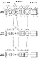
まず、第1の実施形態に係る内視鏡用対物レンズについて、図1を用いて説明する。図1は本発明の実施例1に係る内視鏡用対物レンズの基本構成を示すものである。なお、図1に示す左右方向に延びる1点鎖線の直線は光軸である。また、図1に示す最遠点観察状態とは、最遠点を観察するとき(最遠点にピントが合っているとき)のレンズ配置状態を示し、中間点観察状態とは、中間点を観察するとき(中間点にピントが合っているとき)のレンズ配置状態を示し、最近点観察状態とは、最近点を観察するとき(最近点にピントが合っているとき)のレンズ配置状態を示している。このことは、実施例2、4に係る各内視鏡用対物レンズの基本構成を示す図2、3においても同様である。
First, the endoscope objective lens according to the first embodiment will be described with reference to FIG. FIG. 1 shows a basic configuration of an endoscope objective lens according to
図1に示すように、この内視鏡用対物レンズは、物体側より順に、負の屈折力を有する固定の第1レンズ群G1、正の屈折力を有し光軸に沿って移動可能な第2レンズ群G2、負の屈折力を有し光軸に沿って移動可能な第3レンズ群G3、正の屈折力を有する固定の第4レンズ群G4、および正の屈折力を有し光軸に沿って移動可能な第5レンズ群G5を配してなる。 As shown in FIG. 1, the endoscope objective lens is, in order from the object side, a fixed first lens group G 1 having a negative refractive power, and has a positive refractive power and is movable along the optical axis. Second lens group G 2 , third lens group G 3 having negative refractive power and movable along the optical axis, fixed fourth lens group G 4 having positive refractive power, and positive refractive power formed by arranging the fifth lens group G 5 is movable along the optical axis has a.
この内視鏡用対物レンズは、第2レンズ群G2と第3レンズ群G3との2群からレンズ群A(GA)が構成されている。そして、観察位置が最遠点から中間点に至るまでの遠点側観察状態における第1のピント調整は、図1の上段に示す最遠点観察状態から、第2レンズ群G2が光軸に沿って物体側に、同時に、第3レンズ群G3が光軸に沿って像側に、それぞれの移動軌跡の形状が互いに異なるように移動することにより、行なわれるようになっている。 The endoscope objective lens, the lens group from two groups of the second lens group G 2 and the third lens group G 3 A (G A) is configured. The first focal adjustment observation position at the far point side observation state up to the intermediate point from the farthest point from the farthest point observation state shown in the upper part of FIG. 1, the second lens group G 2 is the optical axis the object along the same time, the third lens group G 3 is on the image side along the optical axis, by the shape of each of the movement locus moves differently from each other, is adapted to be performed.
また、この内視鏡用対物レンズは、1つの第5レンズ群G5からレンズ群B(GB)が構成されている。そして、観察位置が中間点から最近点に至るまでの近点側拡大観察状態における第2のピント調整は、図1の中段に示す中間点観察状態から、第5レンズ群G5が光軸に沿って物体側に移動することにより、行なわれるようになっている。 Further, the endoscope objective lens, one of the fifth lens group G lens group from 5 B (G B) is formed. The second focal adjustment in the near point side magnifying observation state to the observation position reaches the midpoint nearest point from the midpoint observation state shown in the middle part of FIG. 1, the fifth lens group G 5 is the optical axis This is done by moving along the object side.
なお、遠点側観察状態とは、物体距離が遠く、画角が広く、広い範囲の観察に適した状態を表し、一方、近点側拡大観察状態とは、物体距離が近く、一部分を拡大した観察に適した状態を表す。また、最遠点観察状態とは、遠点側観察状態において、全系の倍率が最も低くなった状態となっており、一方、最近点観察状態とは、近点側拡大観察状態において、全系の倍率が最も高くなった状態となっている。このことは、実施例2、4に係る各内視鏡用対物レンズの基本構成を示す図2、3においても同様である。 The far point side observation state represents a state in which the object distance is long, the angle of view is wide, and is suitable for a wide range observation. On the other hand, the near point side observation state is close to the object distance and a part is enlarged. This represents a state suitable for observation. The farthest point observation state is the state where the magnification of the entire system is the lowest in the far point side observation state, while the closest point observation state is the entire point in the near point side observation state. The system has the highest magnification. The same applies to FIGS. 2 and 3 showing the basic configuration of each endoscope objective lens according to Examples 2 and 4. FIG.
さらに、この内視鏡用対物レンズの第3レンズ群G3と第4レンズ群G4との間には、第1のピント調整中、第3レンズ群G3と共に移動する絞り1が配設されている。また、第5レンズ群G5の像側には光路変換用プリズム2およびカバーガラス3が配設されるとともに、このカバーガラス3の像側には図示されないCCD素子やイメージガイドファイバが配設されて画像情報が伝達されるようになっている。なお、図1において絞り1は、光軸上で第3レンズ群G3の最も物体側の面に接するように配設されており、第1のピント調整の間、第3レンズ群G3と共に像側に移動するように構成されている。
Furthermore, the third lens group G 3 of the endoscope objective lens is provided between the fourth lens group G 4, in adjusting the first focus,
また、この内視鏡用対物レンズは、最も物体側に、第1および第2のピント調整中固定の第1レンズ群からなるレンズ群C(GC)が配置され、さらに課題を解決するための手段の欄に記載された条件式(1)、(2)、(4)、(5)(以下に再掲する)を満足するように構成されている。
1.2 < fM/fF ……(1)
0.9 < |fN/fM| < 1.1 ……(2)
4.0 < DF/fF < 15.0 ……(4)
2.0 < βCN/βCF < 8.0 ……(5)
ただし、
fM :中間点を観察するときのレンズ全体の焦点距離
fF :最遠点を観察するときのレンズ全体の焦点距離
fN :最近点を観察するときのレンズ全体の焦点距離
DF :最遠点を観察するときのレンズ全長(最も物体側に配置されるレンズの物体側の面から、最も像側に配置されるレンズの像側の面までの幾何学的距離)
βCN:最近点を観察するときのレンズ群Cの倍率
βCF:最遠点を観察するときのレンズ群Cの倍率
In addition, in the objective lens for an endoscope, a lens group C (G C ) composed of a first lens group that is fixed during the first and second focus adjustments is arranged on the most object side to further solve the problem. The conditional expressions (1), (2), (4), and (5) (reproduced below) described in the column of means are satisfied.
1.2 <f M / f F ...... (1)
0.9 <| f N / f M | <1.1 ...... (2)
4.0 <D F / f F <15.0 (4)
2.0 < βCN / βCF <8.0 (5)
However,
f M : focal length of the whole lens when observing the intermediate point f F : focal length of the whole lens when observing the farthest point f N : focal length of the whole lens when observing the nearest point D F : Total lens length when observing a far point (geometric distance from the object side surface of the lens arranged closest to the object side to the image side surface of the lens arranged closest to the image side)
β CN : magnification of the lens group C when observing the closest point β CF : magnification of the lens group C when observing the farthest point
なお、上記条件式(1)は、課題を解決するための手段の欄に記載された条件式(3)(以下に再掲する)のように、上限値を規定することが好ましく、図1に示す内視鏡用対物レンズは、この条件式(3)をも満足するように構成されている。
1.2 < fM/fF < 2.5 ……(3)
The conditional expression (1) preferably defines an upper limit value as in the conditional expression (3) described in the column of means for solving the problem (reproduced below). The endoscope objective lens shown is configured to satisfy the conditional expression (3).
1.2 <f M / f F < 2.5 ...... (3)
次に、本発明の第2の実施形態に係る内視鏡用対物レンズについて、図3を用いて説明する。図3は本発明の実施例4に係る内視鏡用対物レンズの基本構成を示すものである。 Next, an endoscope objective lens according to a second embodiment of the present invention will be described with reference to FIG. FIG. 3 shows a basic configuration of an endoscope objective lens according to Example 4 of the present invention.
図3に示すように、この内視鏡用対物レンズは、物体側より順に、負の屈折力を有する固定の第1レンズ群G1、正の屈折力を有する固定の第2レンズ群G2、負の屈折力を有し光軸に沿って移動可能な第3レンズ群G3、正の屈折力を有する固定の第4レンズ群G4、および正の屈折力を有し光軸に沿って移動可能な第5レンズ群G5を配してなる。 As shown in FIG. 3, the endoscope objective lens includes, in order from the object side, a fixed first lens group G 1 having a negative refractive power and a fixed second lens group G 2 having a positive refractive power. A third lens group G 3 having a negative refractive power and movable along the optical axis, a fixed fourth lens group G 4 having a positive refractive power, and a positive refractive power along the optical axis. formed by arranging the fifth lens group G 5 movable Te.
この内視鏡用対物レンズは、1つの第3レンズ群G3からレンズ群A(GA)が構成されている。そして、遠点側観察状態における第1のピント調整は、図3の上段に示す最遠点観察状態から、第3レンズ群G3が光軸に沿って像側に移動することにより、行なわれるようになっている。 The endoscope objective lens, from one of the third lens group G 3 lens group A (G A) is configured. The first focal adjustment at the far point side observation state from the farthest point observation state shown in the upper part of FIG. 3, the third lens group G 3 is moved to the image side along the optical axis, is performed It is like that.
また、この内視鏡用対物レンズは、1つの第5レンズ群G5からレンズ群B(GB)が構成されている。そして、近点側拡大観察状態における第2のピント調整は、図3の中段に示す中間点観察状態から、第5レンズ群G5が光軸に沿って物体側に移動することにより、行なわれるようになっている。 Further, the endoscope objective lens, one of the fifth lens group G lens group from 5 B (G B) is formed. The second focal adjustment in the near point side magnifying observation state, from the midpoint observation state shown in the middle of FIG 3, by the fifth lens group G 5 is moved to the object side along the optical axis, it is performed It is like that.
さらに、この内視鏡用対物レンズには、第2レンズ群G2と第3レンズ群G3との間に、固定の絞り1が配設されている。また、第5レンズ群G5の像側には、第1実施形態と同様に、光路変換用プリズム2およびカバーガラス3が配設されるとともに、このカバーガラス3の像側には図示されないCCD素子やイメージガイドファイバが配設されて画像情報が伝達されるようになっている。
In addition, this endoscope objective lens, between the second lens group G 2 and the third lens group G 3, the
また、この内視鏡用対物レンズは、最も物体側に、第1および第2のピント調整中固定の、第1レンズ群G1および第2レンズ群G2からなるレンズ群C(GC)が配置され、さらに第1実施形態と同様に、上記条件式(1)〜(5)を満足するように構成されている。 In addition, the endoscope objective lens has a lens group C (G C ) including the first lens group G 1 and the second lens group G 2 that is fixed to the most object side during the first and second focus adjustments. Further, as in the first embodiment, the above conditional expressions (1) to (5) are satisfied.
第1および第2の実施形態のような構成による内視鏡用対物レンズによれば、近点側拡大観察状態でのピント調整を行なう際の観察倍率の変化を少なくすることができ、ピント調整を容易に行なうことが可能である。 According to the endoscope objective lens having the configuration as in the first and second embodiments, it is possible to reduce a change in observation magnification when performing focus adjustment in the near-point side enlarged observation state, and focus adjustment. Can be easily performed.
条件式(1)は、第1のピント調整における焦点距離の変動に伴う全系の倍率変化を規定するものであり、この下限値を下回る場合には、同じ倍率を得ようとするとライトガイドからの照明光がうまくあたらない部分を観察することになってしまう。また、中間点での倍率低下につながってしまう。 Conditional expression (1) prescribes a change in magnification of the entire system accompanying a change in focal length in the first focus adjustment. If the lower limit is not reached, an attempt to obtain the same magnification will result from the light guide. The part where the illumination light does not hit well will be observed. In addition, the magnification at the midpoint is reduced.
条件式(2)は、第2のピント調整における焦点距離の変動に伴う全系の倍率変化を規定するものであり、この範囲外に設定されると、ピント調整において観察倍率が大きく変化してしまうため、観察対象が視野から外れ易くなり、ピント調整を行なうことが困難となる。 Conditional expression (2) prescribes a change in magnification of the entire system accompanying a change in focal length in the second focus adjustment. If set outside this range, the observation magnification greatly changes in the focus adjustment. As a result, the observation target is likely to be out of the field of view, making it difficult to adjust the focus.
条件式(3)は、条件式(1)では設定されていない上限値を規定したものであり、この上限値を上回ると、レンズ部の移動量が大きくなり、レンズ全体の大型化につながることで内視鏡の先端部分も長くなり、患者の苦痛が増大したり内視鏡の操作が難しくなったりする。 Conditional expression (3) defines an upper limit value that is not set in conditional expression (1). If the upper limit value is exceeded, the amount of movement of the lens portion increases, leading to an increase in the size of the entire lens. As a result, the distal end portion of the endoscope becomes longer, which increases patient pain and makes it difficult to operate the endoscope.
条件式(4)は、最遠点観察状態でのレンズ全長とレンズ全体の焦点距離との比を規定するものであり、この上限値を上回ると、内視鏡先端部が長くなり患者の苦痛が増大したり、内視鏡操作が難しくなったりする。一方、この下限値を下回ると、ピント調整を行なうためのレンズ群の移動スペースが少なくなり、ピント調整し得る観察位置が狭い範囲に限られてしまう。 Conditional expression (4) defines the ratio of the total lens length in the farthest point observation state to the focal length of the entire lens. If this upper limit is exceeded, the endoscope tip becomes longer and the patient suffers. Increase, or endoscope operation becomes difficult. On the other hand, if the lower limit value is not reached, the movement space of the lens group for performing focus adjustment is reduced, and the observation position where focus adjustment can be performed is limited to a narrow range.
条件式(5)は、最近点観察状態と最遠点観察状態とにおけるレンズ群C(GC)の倍率比を規定するものである。一般にズームレンズと称されるレンズではこの条件式(5)に対応する値が1となるが、本発明による内視鏡用対物レンズでは、最遠点観察状態から最近点観察状態に移行する場合、最近点観察状態に近づくにつれ物体距離も短くなり、それにより観察対象が拡大して見える作用を利用して倍率を変化させていることを示している。この下限値を下回ると最近点観察状態での倍率が不足する。また、この上限値を上回ると最近点観察状態での物体距離が近くなりすぎ、ライトガイドからの照明光がうまくあたらない部分を観察することになってしまう。 Conditional expression (5) defines the magnification ratio of the lens group C (G C ) in the closest point observation state and the farthest point observation state. In a lens generally referred to as a zoom lens, the value corresponding to the conditional expression (5) is 1, but in the case of an endoscope objective lens according to the present invention, a transition is made from the farthest point observation state to the closest point observation state. As the closest point observation state is approached, the object distance is also shortened, which indicates that the magnification is changed by utilizing the action that the observation object appears to expand. Below this lower limit, the magnification in the closest point observation state is insufficient. If the upper limit value is exceeded, the object distance in the closest point observation state becomes too close, and the portion where the illumination light from the light guide does not hit well is observed.
以下、本発明の実施例1〜4について具体的に説明する。 Examples 1 to 4 of the present invention will be specifically described below.
<実施例1>
実施例1に係る内視鏡用対物レンズの最遠点観察状態、中間点観察状態および最近点観察状態における基本構成を図1に示す。
<Example 1>
FIG. 1 shows a basic configuration of the endoscope objective lens according to Example 1 in the farthest point observation state, the intermediate point observation state, and the closest point observation state.
実施例1に係る内視鏡用対物レンズは、第1の実施形態として説明した通り、物体側より順に、負の屈折力を有する固定の第1レンズ群G1、正の屈折力を有し光軸に沿って移動可能な第2レンズ群G2、負の屈折力を有し光軸に沿って移動可能な第3レンズ群G3、正の屈折力を有する固定の第4レンズ群G4、および正の屈折力を有し光軸に沿って移動可能な第5レンズ群G5を配してなる。 As described in the first embodiment, the endoscope objective lens according to Example 1 has, in order from the object side, a fixed first lens group G 1 having a negative refractive power and a positive refractive power. A second lens group G 2 movable along the optical axis, a third lens group G 3 having negative refractive power and movable along the optical axis, and a fixed fourth lens group G having positive refractive power 4, and formed by arranging the fifth lens group G 5 is movable along the positive optical axis has a refractive power.
第1レンズ群G1は、像側に凹面を向けた平凹レンズからなる第1レンズL1と、物体側の面に比して像側の面が強い曲率を持つ両凹レンズからなる第2レンズL2と、両凸レンズからなる第3レンズL3とから構成されており、第2レンズL2と第3レンズL3とは互いに接合されている。また、第1の実施形態として説明した通り、この実施例1では、第1レンズ群G1によりレンズ群C(GC)が構成されている。 The first lens group G 1, the second lens comprising a biconcave lens having a first lens L 1 composed of a plano-concave lens having a concave surface facing the image side, the face is strong curvature of the image side than the object-side surface and L 2, and a third lens L 3 Metropolitan having a biconvex lens, the second lens L 2 and third lens L 3 are bonded to each other. Further, as described as the first embodiment, in the first embodiment, the first lens group G 1 lens group C (G C) is constituted.
第2レンズ群G2は、両凸レンズからなる1つの第4レンズL4から構成されており、第3レンズ群G3は、像側に凹面を向けた平凹レンズからなる1つの第5レンズL5から構成されている。また、第1の実施形態として説明した通り、この実施例1では、第2レンズ群G2と第3レンズ群G3との2群からレンズ群A(GA)が構成されている。そして、遠点側観察状態における第1のピント調整は、図1の上段に示す最遠点観察状態から、第2レンズ群G2(第4レンズL4)が光軸に沿って物体側に、同時に、第3レンズ群G3(第5レンズL5)が光軸に沿って像側に、それぞれの移動軌跡の形状が互いに異なるように移動することにより、行なわれるようになっている(第2のピント調整中は移動しない)。 The second lens group G 2 is composed of one of the fourth lens L 4, which is a biconvex lens, the third lens group G 3 is one of the fifth lens formed of a plano-concave lens having a concave surface facing the image side L It is composed of five . Further, as described in the first embodiment, in Example 1, the lens group A (G A ) is composed of two groups of the second lens group G 2 and the third lens group G 3 . The first focus adjustment in the far-point side observation state is such that the second lens group G 2 (fourth lens L 4 ) moves from the farthest point observation state shown in the upper part of FIG. 1 to the object side along the optical axis. At the same time, the third lens group G 3 (fifth lens L 5 ) moves toward the image side along the optical axis so that the shapes of the respective movement trajectories are different from each other (see FIG. It does not move during the second focus adjustment).
また、この実施例1では、光軸上で第5レンズL5の物体側の面に接するように絞り1が配設されており、この絞り1は、第1のピント調整の間、第5レンズL5と共に像側に移動するように構成されている(第2のピント調整中は移動しない)。
Further, in the first embodiment, on the optical axis and 1 stop in contact with the surface on the object side of the fifth lens L 5 is disposed, the
第4レンズ群G4は、像側の面に比して物体側の面が強い曲率を持つ両凸レンズからなる第6レンズL6と、像側に凹面を向けた負のメニスカスレンズからなる第7レンズL7とから構成されている。 The fourth lens group G 4 includes a sixth lens L 6 composed of a double convex lens surface on the object side than the surface on the image side has a stronger curvature, the a negative meniscus lens having a concave surface on the image side and a 7 lens L 7 Prefecture.
第5レンズ群G5は、両凸レンズからなる第8レンズL8と、物体側に凹面を向けた負のメニスカスレンズからなる第7レンズL7とが互いに接合されてなる1つの接合レンズから構成されている。また、第1の実施形態として説明した通り、この実施例1では、1つの第5レンズ群G5からレンズ群B(GB)が構成されている。そして、近点側拡大観察状態における第2のピント調整は、図1の中段に示す中間点観察状態から、第5レンズ群G5が光軸に沿って物体側に移動することにより、行なわれるようになっている(第1のピント調整中は移動しない)。 The fifth lens group G 5 is composed of both the eighth lens L 8 made of a convex lens, a seventh lens L 7 consisting of a negative meniscus lens having a concave surface on the object side is formed by bonding together one cemented lens Has been. Further, as described as the first embodiment, in the first embodiment, one of the fifth lens group G lens group from 5 B (G B) is formed. The second focal adjustment in the near point side magnifying observation state, from the midpoint observation state shown in the middle of Figure 1, by the fifth lens group G 5 is moved to the object side along the optical axis, it is performed (It does not move during the first focus adjustment).
なお、第5レンズ群G5の移動を手動操作することにより、第2のピント調整が行なわれる構成とすることもできるが、この第2のピント調整を自動化するオートフォーカス機構を備えることも可能である。このようなオートフォーカス機構は、例えば、第5レンズ群G5を光軸に沿って移動させる駆動機構と、所定の情報(CCD素子上に形成された画像情報や、内視鏡先端から観察対象までの距離情報等)に基づき、駆動機構を制御する制御手段とにより構成することができる。このことは、以下に示す実施例2〜4についても同様である。 Note that by manually operating the movement of the fifth lens group G 5, can also be configured such that the second focal adjustment is performed, it can also be provided with an auto-focus mechanism that automates the second focal adjustment It is. Such auto-focus mechanism, for example, a drive mechanism for moving the fifth lens group G 5 to the optical axis, and the image information formed on the predetermined information (CCD elements, the observation target from the endoscope distal end And a control means for controlling the drive mechanism based on the distance information and the like. The same applies to Examples 2 to 4 shown below.
実施例1に係る内視鏡用対物レンズの各レンズ面の曲率半径R、各レンズの中心厚および各レンズ間の空気間隔(以下「軸上面間隔」と称す)D、各レンズのd線における屈折率Ndおよび各レンズのd線におけるアッベ数νdの値を、表1の上段に示す。なお、表1および以下の表2〜4において、曲率半径Rおよび軸上面間隔Dは最遠点観察状態における焦点距離を1.0として規格化された値であり、また、各記号に対応させた数字は物体側より順次増加するようになっている。 The radius of curvature R of each lens surface of the objective lens for endoscope according to the first embodiment, the center thickness of each lens, the air space between each lens (hereinafter referred to as “axial upper surface space”) D, and the d-line of each lens The values of the refractive index N d and the Abbe number ν d in the d-line of each lens are shown in the upper part of Table 1. In Table 1 and Tables 2 to 4 below, the radius of curvature R and the axial top surface distance D are values normalized with the focal length in the farthest point observation state being 1.0, and numbers corresponding to each symbol. Increases sequentially from the object side.
また、表1の下段には、実施例1の最遠点観察状態、中間点観察状態および最近点観察状態における物体距離(軸上面間隔Dと同様に規格化されている。以下の表2〜4においても同様)、倍率、および軸上面間隔Dの可変群間隔1〜5が示されている。これによれば、実施例1に係る内視鏡用対物レンズは、近点側拡大観察状態でのピント調整を行なう際の観察倍率の変化が小さく、ピント調整を容易に行なえることが明らかである。
In the lower part of Table 1, the object distances in the farthest point observation state, the intermediate point observation state, and the closest point observation state of Example 1 (standardized in the same manner as the axial top surface distance D. Tables 2 and 2 below). 4 is also shown), and the

<実施例2>
実施例2に係る内視鏡用対物レンズの最遠点観察状態、中間点観察状態および最近点観察状態における基本構成を図2に示す。
実施例2に係る内視鏡用対物レンズは、実施例1のものと同様に、物体側より順に、負の屈折力を有する固定の第1レンズ群G1、正の屈折力を有し光軸に沿って移動可能な第2レンズ群G2、負の屈折力を有し光軸に沿って移動可能な第3レンズ群G3、正の屈折力を有する固定の第4レンズ群G4、および正の屈折力を有し光軸に沿って移動可能な第5レンズ群G5を配してなる。
<Example 2>
FIG. 2 shows a basic configuration of the endoscope objective lens according to Example 2 in the farthest point observation state, the intermediate point observation state, and the closest point observation state.
In the same manner as in Example 1, the endoscope objective lens according to Example 2 is, in order from the object side, a fixed first lens group G 1 having negative refractive power, light having positive refractive power, and light. A second lens group G 2 movable along the axis, a third lens group G 3 movable with a negative refractive power along the optical axis, and a fixed fourth lens group G 4 with a positive refractive power. , and formed by arranging the fifth lens group G 5 is movable along the positive optical axis has a refractive power.
第1レンズ群G1、第2レンズ群G2、および第3レンズ群G3は、実施例1と略同様の構成とされているが、絞り1は、第2レンズ群G2と第3レンズ群G3との間に配置されている。また、第1レンズ群G1からレンズ群C(GC)が構成されている点、および第2レンズ群G2と第3レンズ群G3との2群からレンズ群A(GA)が構成されている点は、実施例1と同様であり、第1のピント調整におけるレンズ移動についても、実施例1と略同様の構成とされている。ただし、第1のピント調整中、絞り1は移動しない(第2のピント調整中も移動しない)。
The first lens group G 1 , the second lens group G 2 , and the third lens group G 3 have substantially the same configuration as that of the first embodiment, but the
第4レンズ群G4は、両凸レンズからなる第6レンズL6と、物体側の面に比して像側の面が強い曲率を持つ両凸レンズからなる第7レンズL7と、像側の面に比して物体側の面が強い曲率を持つ両凹レンズからなる第8レンズL8とから構成されており、第7レンズL7と第8レンズL8とは互いに接合されている。 The fourth lens group G 4 includes a sixth lens L 6 having a biconvex lens, a seventh lens L 7 of the image side surface than the surface on the object side is a biconvex lens having a strong curvature, the image side are composed of the eighth lens L 8 Metropolitan the surface on the object side is a biconcave lens having a strong curvature than the face, the seventh lens L 7 and the eighth lens L 8 are joined together.
第5レンズ群G5は、両凸レンズからなる第9レンズL9と、物体側に凹面を向けた平凹レンズからなる第10レンズL10とが互いに接合されてなる1つの接合レンズから構成されている。なお、1つの第5レンズ群G5からレンズ群B(GB)が構成されている点は実施例1と同様であり、第2のピント調整におけるレンズ移動についても、実施例1と略同様の構成とされている。 The fifth lens group G 5 includes a ninth lens L 9, which is a biconvex lens, consists tenth lens L 10 and is formed by bonding together one cemented lens consisting of a plano-concave lens having a concave surface on the object side Yes. Incidentally, one of the fifth lens group G lens group from 5 B (G B) that is configured the same as in Example 1, also for the lens movement in the second focal adjustment, substantially the same manner as in Example 1 It is made up of.
実施例2に係る内視鏡用対物レンズの各レンズ面の曲率半径R、軸上面間隔D、各レンズのd線における屈折率Ndおよび各レンズのd線におけるアッベ数νdの値を、表2の上段に示す。 The values of the curvature radius R of each lens surface, the axial top surface distance D, the refractive index N d of each lens at the d-line, and the Abbe number ν d at the d-line of each lens, of the objective lens for an endoscope according to Example 2, Shown in the upper part of Table 2.
また、表2の下段には、実施例2の最遠点観察状態、中間点観察状態および最近点観察状態における物体距離、倍率、および軸上面間隔Dの可変群間隔1〜6の値が示されている。これによれば、実施例2に係る内視鏡用対物レンズは、近点側拡大観察状態でのピント調整を行なう際の観察倍率の変化が小さく、ピント調整を容易に行なえることが明らかである。
The lower part of Table 2 shows the object distance, magnification, and values of the
<実施例3>
実施例3に係る内視鏡用対物レンズは、実施例2と略同様に構成されており(ただし、以下の表3に示すように、第6レンズL6の両面は共に非球面とされている)、また、第1および第2のピント調整におけるレンズ移動についても、実施例2と略同様の構成とされている。このため、実施例2に係る内視鏡用対物レンズの最遠点観察状態、中間点観察状態および最近点観察状態における基本構成の図示は省略する。
<Example 3>
An endoscope objective lens according to Example 3 is substantially the same structure as in Example 2 (however, as shown in Table 3 below, both surfaces of the sixth lens L 6 is set to both aspherical In addition, the lens movement in the first and second focus adjustments is substantially the same as that of the second embodiment. For this reason, illustration of the basic configuration in the farthest point observation state, the intermediate point observation state, and the closest point observation state of the endoscope objective lens according to Example 2 is omitted.
実施例3に係る内視鏡用対物レンズの各レンズ面の曲率半径R、軸上面間隔D、各レンズのd線における屈折率Ndおよび各レンズのd線におけるアッベ数νdの値を、表3の上段に示す。 The values of the curvature radius R of each lens surface, the axial top surface distance D, the refractive index N d of each lens at the d-line, and the Abbe number ν d at the d-line of each lens of the objective lens for an endoscope according to Example 3, Shown in the upper part of Table 3.
また、表3の中段には、実施例3の最遠点観察状態、中間点観察状態および最近点観察状態における物体距離、倍率、および軸上面間隔Dの可変群間隔1〜6の値が示されている。これによれば、実施例3に係る内視鏡用対物レンズは、近点側拡大観察状態でのピント調整を行なう際の観察倍率の変化が小さく、ピント調整を容易に行なえることが明らかである。
The middle part of Table 3 shows the object distance, magnification, and values of
なお、表3および以下の表4において、面番号の左側に*印が付された面は、下記非球面式により形状が規定される非球面とされている。実施例3および以下の実施例4において、これらの非球面の曲率半径Rは、各表において光軸上での曲率半径Rの値として示しているが、対応するレンズ構成図においては図面を見やすくするため、引出線は必ずしも光軸との交点から引き出されていないものがある。
表3の下段には、各非球面に対応する各定数K、A4、A6、A8の値が示されている。
In Table 3 and Table 4 below, the surface marked with * on the left side of the surface number is an aspherical surface whose shape is defined by the following aspherical expression. In Example 3 and Example 4 below, the radius of curvature R of these aspheric surfaces is shown as the value of the radius of curvature R on the optical axis in each table, but the drawing is easy to see in the corresponding lens configuration diagram. Therefore, some lead lines are not necessarily drawn from the intersection with the optical axis.
In the lower part of Table 3, the values of the constants K, A 4 , A 6 , A 8 corresponding to the respective aspheric surfaces are shown.
<実施例4>
実施例4に係る内視鏡用対物レンズの最遠点観察状態、中間点観察状態および最近点観察状態における基本構成を図3に示す。
実施例4に係る内視鏡用対物レンズは、第2の実施形態として説明した通り、物体側より順に、負の屈折力を有する固定の第1レンズ群G1、正の屈折力を有する固定の第2レンズ群G2、負の屈折力を有し光軸に沿って移動可能な第3レンズ群G3、正の屈折力を有する固定の第4レンズ群G4、および正の屈折力を有し光軸に沿って移動可能な第5レンズ群G5を配してなる。
<Example 4>
FIG. 3 shows a basic configuration of the endoscope objective lens according to Example 4 in the farthest point observation state, the intermediate point observation state, and the closest point observation state.
In the endoscope objective lens according to Example 4, as described in the second embodiment, in order from the object side, a fixed first lens group G 1 having a negative refractive power and a fixed having a positive refractive power. The second lens group G 2 , the third lens group G 3 having negative refractive power and movable along the optical axis, the fixed fourth lens group G 4 having positive refractive power, and the positive refractive power formed by arranging the fifth lens group G 5 is movable along the optical axis has a.
第1レンズ群G1は、像側に凹面を向けた平凹レンズからなる第1レンズL1と、像側に凹面を向けた負のメニスカスレンズからなる第2レンズL2と、両凸レンズからなる第3レンズL3とから構成されており、第2レンズL2と第3レンズL3とは互いに接合されている。 The first lens group G 1 has a first lens L 1 composed of a plano-concave lens having a concave surface facing the image side, a negative second lens L 2 formed of a meniscus lens having a concave surface on the image side, a biconvex lens and a third lens L 3 Prefecture, the second lens L 2 and third lens L 3 are bonded to each other.
第2レンズ群G2は、物体側の面に比して像側の面が強い曲率を持つ両凸レンズからなる1つの第4レンズL4から構成されており、第3レンズ群G3は、像側に凹面を向けた平凹レンズからなる1つの第5レンズL5から構成されている。また、第2の実施形態として説明した通り、この実施例4では、第1レンズ群G1および第2レンズ群G2からレンズ群C(GC)が構成されており、1つの第3レンズ群G3からレンズ群A(GA)が構成されている。そして、遠点側観察状態における第1のピント調整は、図3の上段に示す最遠点観察状態から、第3レンズ群G3(第5レンズL5)が光軸に沿って像側に移動することにより、行なわれるようになっている(第2のピント調整中は移動しない)。また、第2の実施形態として説明した通り、この実施例4では、第2レンズ群G2と第3レンズ群G3との間に、固定の絞り1が配置されている。
The second lens group G 2 is composed of the fourth lens L 4 in one of a biconvex lens including the image side surface than the surface on the object side has a stronger curvature, the third lens group G 3 is and a single fifth lens L 5 formed of a plano-concave lens having a concave surface facing the image side. Further, as described as the second embodiment, in the fourth embodiment, the lens group from the first lens group G 1 and the second lens group G 2 C (G C) is configured, one of the third lens The lens group A (G A ) is composed of the group G 3 . The first focus adjustment in the far-point side observation state is performed by moving the third lens group G 3 (fifth lens L 5 ) from the farthest point observation state shown in the upper part of FIG. 3 to the image side along the optical axis. This is performed by moving (does not move during the second focus adjustment). Further, as described as the second embodiment, in the fourth embodiment, between the second lens group G 2 and the third lens group G 3, the
第4レンズ群G4は、両面が共に非球面とされた正の屈折力を有する第6レンズL6と、物体側の面に比して像側の面が強い曲率を持つ両凸レンズからなる第7レンズL7と、像側の面に比して物体側の面が強い曲率を持つ両凹レンズからなる第8レンズL8とから構成されており、第7レンズL7と第8レンズL8とは互いに接合されている。 The fourth lens group G 4 includes a sixth lens L 6 having a positive refractive power having both surfaces set to both aspheric surface on the image side than the object-side surface is a biconvex lens having a strong curvature The seventh lens L 7 is composed of a seventh lens L 7 and an eighth lens L 8 made of a biconcave lens whose surface on the object side has a larger curvature than the surface on the image side. 8 are joined to each other.
第5レンズ群G5は、両凸レンズからなる第9レンズL9と、物体側に凹面を向けた平凹レンズからなる第10レンズL10とが互いに接合されてなる1つの接合レンズから構成されている。また、第2の実施形態として説明した通り、この実施例4では、1つの第5レンズ群G5からレンズ群B(GB)が構成されており、第2のピント調整は、図3の中段に示す中間点観察状態から、第5レンズ群G5が光軸に沿って物体側に移動することにより、行なわれるようになっている(第1のピント調整中は移動しない)。 The fifth lens group G 5 includes a ninth lens L 9, which is a biconvex lens, consists tenth lens L 10 and is formed by bonding together one cemented lens consisting of a plano-concave lens having a concave surface on the object side Yes. Further, as described as the second embodiment, in the fourth embodiment is configured that one of the fifth lens group G 5 lens group from B (G B), the second focal adjustment, in Fig. 3 from the midpoint observation state shown in the middle, the fifth lens group G 5 is by moving the object along the optical axis, in which (during the first focal adjustment does not move) which come to be performed.
実施例4に係る内視鏡用対物レンズの各レンズ面の曲率半径R、軸上面間隔D、各レンズのd線における屈折率Ndおよび各レンズのd線におけるアッベ数νdの値を、表4の上段に示す。 The values of the curvature radius R of each lens surface, the axial top surface distance D, the refractive index N d of each lens at the d-line, and the Abbe number ν d at the d-line of each lens, of the objective lens for endoscope according to Example 4, Shown in the upper part of Table 4.
また、表4の中段には、実施例4の最遠点観察状態、中間点観察状態および最近点観察状態における物体距離、倍率、および軸上面間隔Dの可変群間隔1〜4の値が示されている。これによれば、実施例4に係る内視鏡用対物レンズは、近点側拡大観察状態でのピント調整を行なう際の観察倍率の変化が小さく、ピント調整を容易に行なえることが明らかである。
さらに、表4の下段には、各非球面に対応する各定数K、A4、A6、A8の値が示されている。
Further, the middle part of Table 4 shows the object distance, magnification, and values of the
Furthermore, the lower part of Table 4 shows the values of the constants K, A 4 , A 6 , A 8 corresponding to each aspheric surface.
表5に、実施例1〜4における上記各条件式(1)〜(5)に対応する各値を示す。実施例1〜4は対応する各条件式(1)〜(5)を全て満足している。 Table 5 shows values corresponding to the conditional expressions (1) to (5) in Examples 1 to 4. Examples 1 to 4 satisfy all the corresponding conditional expressions (1) to (5).
図4〜7に、実施例1〜4の最遠点観察状態、中間点観察状態および最近点観察状態における諸収差(球面収差、非点収差、ディストーション、および倍率色収差)を示す。これらの収差図においてωは半画角を示す。図4〜7に示すように、各実施例1〜4によれば上述した各収差をすべて良好なものとすることができる。 4 to 7 show various aberrations (spherical aberration, astigmatism, distortion, and lateral chromatic aberration) in the farthest point observation state, the intermediate point observation state, and the closest point observation state of Examples 1 to 4. FIG. In these aberration diagrams, ω represents a half angle of view. As shown in FIGS. 4-7, according to each Example 1-4, all the aberrations mentioned above can be made favorable.
なお、本発明の内視鏡用対物レンズとしては、上記実施例のものに限られるものではなく種々の態様の変更が可能であり、例えば各レンズの曲率半径Rおよび軸上面間隔Dを適宜変更することが可能である。 Note that the endoscope objective lens of the present invention is not limited to the above-described embodiment, and various modifications can be made. For example, the curvature radius R and the axial top surface distance D of each lens can be appropriately changed. Is possible.
また、上記各実施例に係る内視鏡用対物レンズでは、レンズ群A(GA)を構成するレンズと、レンズ群B(GB)を構成するレンズとが、互いに重複していない構成とされているが、レンズ群A(GA)を構成するレンズの一部が、レンズ群B(GB)の一部または全部を構成したり、レンズ群B(GB)を構成するレンズの一部が、レンズ群A(GA)の一部または全部を構成したりすることも可能である。 In the endoscope objective lens according to each of the above embodiments, the lens constituting the lens group A (G A ) and the lens constituting the lens group B (G B ) do not overlap each other. has been a part of the lenses constituting the lens group a (G a) is, constitutes a part or the whole of the lens group B (G B) or, in the lenses of the lens group B and (G B) Part of the lens group A (G A ) may constitute part or all of the lens group A.
また、各実施例に係る内視鏡用対物レンズに非球面、GRINレンズ、回折光学素子を付加、あるいは代替して、色収差や他の諸収差の補正を行うことも可能である。 In addition, an aspherical surface, a GRIN lens, and a diffractive optical element may be added to or replaced with the endoscope objective lens according to each embodiment to correct chromatic aberration and other various aberrations.
L1〜L10 レンズ
G1〜G5 レンズ群
R1〜R22 曲率半径
D1〜D21 軸上面間隔
1 絞り
2 光路変換用プリズム
3 CCDカバーガラス
L 1 ~L 10 lens G 1 ~G 5 lens group R 1 to R 22 radius of curvature D 1 to D 21
Claims (7)
前記第3レンズ群は光軸方向に移動可能なレンズ群Aを構成し、
前記第5レンズ群は光軸方向に移動可能なレンズ群Bを構成し、
観察位置が最遠点から中間点までの第1のピント調整は、前記最遠点を観察するときのレンズ配置状態から、前記レンズ群Aを移動させることにより行ない、前記中間点から最近点までの第2のピント調整は、前記中間点を観察するときのレンズ配置状態から、前記レンズ群Bを移動させることにより行なうように構成され、
以下の条件式(1)および(2)を満足していることを特徴とする内視鏡用対物レンズ。
1.2 < fM/fF ……(1)
0.9 < |fN/fM| < 1.1 ……(2)
ただし、
fM :中間点を観察するときのレンズ全体の焦点距離
fF :最遠点を観察するときのレンズ全体の焦点距離
fN :最近点を観察するときのレンズ全体の焦点距離 In order from the object side, a first lens group having negative refractive power, a second lens group having positive refractive power, a third lens group having negative refractive power, a fourth lens group having positive refractive power, and A fifth lens group having a positive refractive power,
The third lens group constitutes a lens group A movable in the optical axis direction ,
The fifth lens group constitutes a lens group B movable in the optical axis direction,
The first focus adjustment from the farthest point to the intermediate point is performed by moving the lens group A from the lens arrangement state when observing the farthest point, and from the intermediate point to the nearest point. The second focus adjustment is configured to be performed by moving the lens group B from the lens arrangement state when observing the intermediate point.
An endoscope objective lens characterized by satisfying the following conditional expressions (1) and (2):
1.2 <f M / f F ...... (1)
0.9 <| f N / f M | <1.1 ...... (2)
However,
f M : focal length of the whole lens when observing the intermediate point f F : focal length of the whole lens when observing the farthest point f N : focal length of the whole lens when observing the nearest point
前記第2レンズ群および第3レンズ群は光軸方向に移動可能なレンズ群Aを構成し、 The second lens group and the third lens group constitute a lens group A movable in the optical axis direction,
前記第5レンズ群は光軸方向に移動可能なレンズ群Bを構成し、 The fifth lens group constitutes a lens group B movable in the optical axis direction,
観察位置が最遠点から中間点までの第1のピント調整は、前記最遠点を観察するときのレンズ配置状態から、前記レンズ群Aを移動させることにより行ない、前記中間点から最近点までの第2のピント調整は、前記中間点を観察するときのレンズ配置状態から、前記レンズ群Bを移動させることにより行なうように構成され、 The first focus adjustment from the farthest point to the intermediate point is performed by moving the lens group A from the lens arrangement state when observing the farthest point, and from the intermediate point to the nearest point. The second focus adjustment is configured to be performed by moving the lens group B from the lens arrangement state when observing the intermediate point.
以下の条件式(1)および(2)を満足していることを特徴とする内視鏡用対物レンズ。 An endoscope objective lens characterized by satisfying the following conditional expressions (1) and (2):
1.2 < f 1.2 <f MM /f/ F FF ……(1) ...... (1)
0.9 < |f 0.9 <| f NN /f/ F MM | < 1.1 ……(2)<1.1 (2)
ただし、 However,
f f M M :中間点を観察するときのレンズ全体の焦点距離: Focal length of the entire lens when observing the midpoint
f f F F :最遠点を観察するときのレンズ全体の焦点距離: The focal length of the entire lens when observing the farthest point
f f N N :最近点を観察するときのレンズ全体の焦点距離: The focal length of the entire lens when observing the nearest point
1.2 < fM/fF < 2.5 ……(3)
4.0 < DF/fF < 15.0 ……(4)
2.0 < βCN/βCF < 8.0 ……(5)
ただし、
DF :最遠点を観察するときのレンズ全長(最も物体側に配置されるレンズの物体側の面から、最も像側に配置されるレンズの像側の面までの幾何学的距離)
βCN:最近点を観察するときのレンズ群Cの倍率
βCF:最遠点を観察するときのレンズ群Cの倍率 The first and second lens groups C that are fixed during focus adjustment are disposed on the most object side, and further satisfy the following conditional expressions (3) to (5): The endoscope objective lens of any one of them.
1.2 <f M / f F < 2.5 ...... (3)
4.0 <D F / f F <15.0 (4)
2.0 < βCN / βCF <8.0 (5)
However,
D F : total lens length when observing the farthest point (geometric distance from the object side surface of the lens arranged closest to the object side to the image side surface of the lens arranged closest to the image side)
β CN : magnification of the lens group C when observing the closest point β CF : magnification of the lens group C when observing the farthest point
る請求項1〜6のうちいずれか1項記載の内視鏡用対物レンズ。 The objective lens for an endoscope according to any one of claims 1 to 6 , further comprising an autofocus mechanism that automates the second focus adjustment.
Priority Applications (6)
| Application Number | Priority Date | Filing Date | Title |
|---|---|---|---|
| JP2005347817A JP5035867B2 (en) | 2005-12-01 | 2005-12-01 | Endoscope objective lens |
| EP06024843A EP1793259B1 (en) | 2005-12-01 | 2006-11-30 | Objective lens for endoscope |
| AT06024843T ATE512382T1 (en) | 2005-12-01 | 2006-11-30 | ENDOSCOPE LENS |
| US11/606,086 US7764437B2 (en) | 2005-12-01 | 2006-11-30 | Objective lens for endoscope |
| CNB2006101636414A CN100447610C (en) | 2005-12-01 | 2006-12-01 | Objective lens for endoscope |
| US12/787,317 US8035900B2 (en) | 2005-12-01 | 2010-05-25 | Objective lens for endoscope |
Applications Claiming Priority (1)
| Application Number | Priority Date | Filing Date | Title |
|---|---|---|---|
| JP2005347817A JP5035867B2 (en) | 2005-12-01 | 2005-12-01 | Endoscope objective lens |
Publications (3)
| Publication Number | Publication Date |
|---|---|
| JP2007155887A JP2007155887A (en) | 2007-06-21 |
| JP2007155887A5 JP2007155887A5 (en) | 2008-12-04 |
| JP5035867B2 true JP5035867B2 (en) | 2012-09-26 |
Family
ID=37695945
Family Applications (1)
| Application Number | Title | Priority Date | Filing Date |
|---|---|---|---|
| JP2005347817A Active JP5035867B2 (en) | 2005-12-01 | 2005-12-01 | Endoscope objective lens |
Country Status (5)
| Country | Link |
|---|---|
| US (2) | US7764437B2 (en) |
| EP (1) | EP1793259B1 (en) |
| JP (1) | JP5035867B2 (en) |
| CN (1) | CN100447610C (en) |
| AT (1) | ATE512382T1 (en) |
Families Citing this family (16)
| Publication number | Priority date | Publication date | Assignee | Title |
|---|---|---|---|---|
| JP2009080413A (en) * | 2007-09-27 | 2009-04-16 | Fujinon Corp | Imaging optical system, image pickup apparatus for endoscope |
| JP5148403B2 (en) * | 2008-07-28 | 2013-02-20 | オリンパスメディカルシステムズ株式会社 | Endoscope objective optical system |
| JP5525790B2 (en) * | 2009-09-30 | 2014-06-18 | オリンパス株式会社 | Optical system |
| US8942530B2 (en) | 2011-09-20 | 2015-01-27 | San Marino Capital, Inc. | Endoscope connector method and apparatus |
| WO2013069265A1 (en) * | 2011-11-09 | 2013-05-16 | 富士フイルム株式会社 | Object lens for endoscope, and endoscope |
| JP5830360B2 (en) * | 2011-11-11 | 2015-12-09 | オリンパス株式会社 | Objective optical system and observation apparatus equipped with the same |
| JP2013104955A (en) * | 2011-11-11 | 2013-05-30 | Olympus Corp | Objective optical system |
| US9019621B2 (en) | 2011-11-11 | 2015-04-28 | Olympus Corporation | Objective optical system and observation apparatus provided with the same |
| JP5860712B2 (en) * | 2012-02-03 | 2016-02-16 | オリンパス株式会社 | Objective optical system and observation apparatus equipped with the same |
| KR20130059150A (en) | 2011-11-28 | 2013-06-05 | 삼성전자주식회사 | Objective lens for endoscopic device, actuator for focusing and endoscopic system |
| KR101404611B1 (en) | 2013-02-12 | 2014-06-09 | (주)시원광기술 | endoscope optical system |
| CN106062609B (en) * | 2014-07-11 | 2018-11-27 | 奥林巴斯株式会社 | Objective lens optical system |
| JP2016133570A (en) * | 2015-01-16 | 2016-07-25 | 株式会社タムロン | Optical system for observation and imaging apparatus including the same |
| JP6807818B2 (en) * | 2017-09-27 | 2021-01-06 | 富士フイルム株式会社 | Objective optical system for endoscopes and endoscopes |
| JP6995978B2 (en) * | 2018-03-27 | 2022-01-17 | オリンパス株式会社 | Objective optical system for endoscopes, image pickup devices, endoscopes and endoscope systems |
| JP6903850B1 (en) * | 2020-03-27 | 2021-07-14 | エスゼット ディージェイアイ テクノロジー カンパニー リミテッドSz Dji Technology Co.,Ltd | Lens system, image pickup device, and moving object |
Family Cites Families (13)
| Publication number | Priority date | Publication date | Assignee | Title |
|---|---|---|---|---|
| JPS5719710A (en) * | 1980-07-09 | 1982-02-02 | Minolta Camera Co Ltd | Zoom lens system capable of macrofocusing |
| JPS60101515A (en) * | 1983-11-08 | 1985-06-05 | Nippon Kogaku Kk <Nikon> | Automatic focus controller |
| JP2736893B2 (en) * | 1988-05-27 | 1998-04-02 | 旭光学工業株式会社 | Macro system of high zoom lens with wide angle |
| JP2567083B2 (en) * | 1989-02-28 | 1996-12-25 | キヤノン株式会社 | Shooting lens |
| JP3034557B2 (en) * | 1990-04-27 | 2000-04-17 | オリンパス光学工業株式会社 | Zoom imaging optical system for endoscope |
| JP2876252B2 (en) | 1990-10-17 | 1999-03-31 | オリンパス光学工業株式会社 | Endoscope objective lens |
| JP3144153B2 (en) * | 1993-04-16 | 2001-03-12 | キヤノン株式会社 | Zoom lens |
| JP4093503B2 (en) * | 1997-06-13 | 2008-06-04 | フジノン株式会社 | Stereoscopic endoscope |
| JPH11352402A (en) * | 1998-06-10 | 1999-12-24 | Nikon Corp | Zoom lens |
| JP3722458B2 (en) | 1999-09-20 | 2005-11-30 | フジノン株式会社 | Endoscope objective lens |
| US6618205B2 (en) | 2001-05-14 | 2003-09-09 | Pentax Corporation | Endoscope objective optical system |
| JP3845331B2 (en) * | 2002-04-05 | 2006-11-15 | ペンタックス株式会社 | Endoscope objective optical system |
| JP4482418B2 (en) * | 2004-10-08 | 2010-06-16 | 富士フイルム株式会社 | Endoscope device |
-
2005
- 2005-12-01 JP JP2005347817A patent/JP5035867B2/en active Active
-
2006
- 2006-11-30 EP EP06024843A patent/EP1793259B1/en not_active Not-in-force
- 2006-11-30 AT AT06024843T patent/ATE512382T1/en not_active IP Right Cessation
- 2006-11-30 US US11/606,086 patent/US7764437B2/en not_active Expired - Fee Related
- 2006-12-01 CN CNB2006101636414A patent/CN100447610C/en not_active Expired - Fee Related
-
2010
- 2010-05-25 US US12/787,317 patent/US8035900B2/en not_active Expired - Fee Related
Also Published As
| Publication number | Publication date |
|---|---|
| CN1975502A (en) | 2007-06-06 |
| JP2007155887A (en) | 2007-06-21 |
| ATE512382T1 (en) | 2011-06-15 |
| CN100447610C (en) | 2008-12-31 |
| US20100232033A1 (en) | 2010-09-16 |
| US7764437B2 (en) | 2010-07-27 |
| US20070127137A1 (en) | 2007-06-07 |
| EP1793259B1 (en) | 2011-06-08 |
| EP1793259A1 (en) | 2007-06-06 |
| US8035900B2 (en) | 2011-10-11 |
Similar Documents
| Publication | Publication Date | Title |
|---|---|---|
| JP5035867B2 (en) | Endoscope objective lens | |
| JP3722458B2 (en) | Endoscope objective lens | |
| JP4450297B2 (en) | Endoscope objective lens | |
| JP5567224B2 (en) | Endoscope objective lens and endoscope | |
| US10251537B2 (en) | Magnifying endoscope optical system | |
| US9645382B2 (en) | Objective lens for endoscope and endoscope | |
| JP6046322B1 (en) | Endoscope variable magnification optical system and endoscope | |
| JP5567225B2 (en) | Endoscope objective lens and endoscope | |
| JP6279195B1 (en) | Endoscope optical system | |
| WO2019180984A1 (en) | Endoscopic objective optical system | |
| JP2008065257A (en) | Zoom lens | |
| JP6001229B2 (en) | Endoscope objective optical system | |
| JP2022033521A (en) | Objective lens for endoscope and endoscope | |
| JP5881481B2 (en) | Variable focus optical system | |
| JP2005091655A (en) | Endoscope objective optical system | |
| JP2001166203A (en) | Objective lens for endoscope of observation distance variable type | |
| CN109983383B (en) | Endoscope objective optical system | |
| WO2013069263A1 (en) | Objective lens for endoscope, and endoscope | |
| JP7358417B2 (en) | Objective lenses for endoscopes and endoscopes | |
| JP4631306B2 (en) | Objective lens and observation optical system |
Legal Events
| Date | Code | Title | Description |
|---|---|---|---|
| A521 | Request for written amendment filed |
Free format text: JAPANESE INTERMEDIATE CODE: A523 Effective date: 20081022 |
|
| A621 | Written request for application examination |
Free format text: JAPANESE INTERMEDIATE CODE: A621 Effective date: 20081022 |
|
| A711 | Notification of change in applicant |
Free format text: JAPANESE INTERMEDIATE CODE: A711 Effective date: 20090910 |
|
| RD02 | Notification of acceptance of power of attorney |
Free format text: JAPANESE INTERMEDIATE CODE: A7422 Effective date: 20100827 |
|
| RD04 | Notification of resignation of power of attorney |
Free format text: JAPANESE INTERMEDIATE CODE: A7424 Effective date: 20100913 |
|
| A131 | Notification of reasons for refusal |
Free format text: JAPANESE INTERMEDIATE CODE: A131 Effective date: 20110816 |
|
| A977 | Report on retrieval |
Free format text: JAPANESE INTERMEDIATE CODE: A971007 Effective date: 20110817 |
|
| A521 | Request for written amendment filed |
Free format text: JAPANESE INTERMEDIATE CODE: A523 Effective date: 20111017 |
|
| A02 | Decision of refusal |
Free format text: JAPANESE INTERMEDIATE CODE: A02 Effective date: 20111108 |
|
| A521 | Request for written amendment filed |
Free format text: JAPANESE INTERMEDIATE CODE: A523 Effective date: 20120208 |
|
| A521 | Request for written amendment filed |
Free format text: JAPANESE INTERMEDIATE CODE: A523 Effective date: 20120214 |
|
| A911 | Transfer to examiner for re-examination before appeal (zenchi) |
Free format text: JAPANESE INTERMEDIATE CODE: A911 Effective date: 20120217 |
|
| A131 | Notification of reasons for refusal |
Free format text: JAPANESE INTERMEDIATE CODE: A131 Effective date: 20120403 |
|
| A521 | Request for written amendment filed |
Free format text: JAPANESE INTERMEDIATE CODE: A523 Effective date: 20120412 |
|
| TRDD | Decision of grant or rejection written | ||
| A01 | Written decision to grant a patent or to grant a registration (utility model) |
Free format text: JAPANESE INTERMEDIATE CODE: A01 Effective date: 20120626 |
|
| A01 | Written decision to grant a patent or to grant a registration (utility model) |
Free format text: JAPANESE INTERMEDIATE CODE: A01 |
|
| A61 | First payment of annual fees (during grant procedure) |
Free format text: JAPANESE INTERMEDIATE CODE: A61 Effective date: 20120628 |
|
| FPAY | Renewal fee payment (event date is renewal date of database) |
Free format text: PAYMENT UNTIL: 20150713 Year of fee payment: 3 |
|
| R150 | Certificate of patent or registration of utility model |
Ref document number: 5035867 Country of ref document: JP Free format text: JAPANESE INTERMEDIATE CODE: R150 Free format text: JAPANESE INTERMEDIATE CODE: R150 |
|
| R250 | Receipt of annual fees |
Free format text: JAPANESE INTERMEDIATE CODE: R250 |
|
| R250 | Receipt of annual fees |
Free format text: JAPANESE INTERMEDIATE CODE: R250 |
|
| R250 | Receipt of annual fees |
Free format text: JAPANESE INTERMEDIATE CODE: R250 |
|
| R250 | Receipt of annual fees |
Free format text: JAPANESE INTERMEDIATE CODE: R250 |
|
| R250 | Receipt of annual fees |
Free format text: JAPANESE INTERMEDIATE CODE: R250 |
|
| R250 | Receipt of annual fees |
Free format text: JAPANESE INTERMEDIATE CODE: R250 |
|
| R250 | Receipt of annual fees |
Free format text: JAPANESE INTERMEDIATE CODE: R250 |
|
| R250 | Receipt of annual fees |
Free format text: JAPANESE INTERMEDIATE CODE: R250 |
|
| R250 | Receipt of annual fees |
Free format text: JAPANESE INTERMEDIATE CODE: R250 |