EP2042832A2 - Navigationsvorrichtung mit GPS Einheit, Beschleunigungs- und Richtungssensor - Google Patents
Navigationsvorrichtung mit GPS Einheit, Beschleunigungs- und Richtungssensor Download PDFInfo
- Publication number
- EP2042832A2 EP2042832A2 EP08016699A EP08016699A EP2042832A2 EP 2042832 A2 EP2042832 A2 EP 2042832A2 EP 08016699 A EP08016699 A EP 08016699A EP 08016699 A EP08016699 A EP 08016699A EP 2042832 A2 EP2042832 A2 EP 2042832A2
- Authority
- EP
- European Patent Office
- Prior art keywords
- acceleration
- ins
- offset
- gps
- unit
- Prior art date
- Legal status (The legal status is an assumption and is not a legal conclusion. Google has not performed a legal analysis and makes no representation as to the accuracy of the status listed.)
- Granted
Links
- 230000001133 acceleration Effects 0.000 title claims abstract description 278
- 238000000034 method Methods 0.000 description 15
- 238000001514 detection method Methods 0.000 description 7
- 230000006870 function Effects 0.000 description 5
- NCGICGYLBXGBGN-UHFFFAOYSA-N 3-morpholin-4-yl-1-oxa-3-azonia-2-azanidacyclopent-3-en-5-imine;hydrochloride Chemical compound Cl.[N-]1OC(=N)C=[N+]1N1CCOCC1 NCGICGYLBXGBGN-UHFFFAOYSA-N 0.000 description 4
- 238000010586 diagram Methods 0.000 description 4
- 238000004891 communication Methods 0.000 description 3
- 239000000470 constituent Substances 0.000 description 3
- 101100179824 Caenorhabditis elegans ins-17 gene Proteins 0.000 description 2
- 101150089655 Ins2 gene Proteins 0.000 description 2
- 238000001914 filtration Methods 0.000 description 1
- 230000010365 information processing Effects 0.000 description 1
- 230000004044 response Effects 0.000 description 1
Images


Classifications
-
- G—PHYSICS
- G01—MEASURING; TESTING
- G01C—MEASURING DISTANCES, LEVELS OR BEARINGS; SURVEYING; NAVIGATION; GYROSCOPIC INSTRUMENTS; PHOTOGRAMMETRY OR VIDEOGRAMMETRY
- G01C21/00—Navigation; Navigational instruments not provided for in groups G01C1/00 - G01C19/00
- G01C21/10—Navigation; Navigational instruments not provided for in groups G01C1/00 - G01C19/00 by using measurements of speed or acceleration
- G01C21/12—Navigation; Navigational instruments not provided for in groups G01C1/00 - G01C19/00 by using measurements of speed or acceleration executed aboard the object being navigated; Dead reckoning
- G01C21/16—Navigation; Navigational instruments not provided for in groups G01C1/00 - G01C19/00 by using measurements of speed or acceleration executed aboard the object being navigated; Dead reckoning by integrating acceleration or speed, i.e. inertial navigation
- G01C21/165—Navigation; Navigational instruments not provided for in groups G01C1/00 - G01C19/00 by using measurements of speed or acceleration executed aboard the object being navigated; Dead reckoning by integrating acceleration or speed, i.e. inertial navigation combined with non-inertial navigation instruments
- G01C21/1654—Navigation; Navigational instruments not provided for in groups G01C1/00 - G01C19/00 by using measurements of speed or acceleration executed aboard the object being navigated; Dead reckoning by integrating acceleration or speed, i.e. inertial navigation combined with non-inertial navigation instruments with electromagnetic compass
-
- G—PHYSICS
- G01—MEASURING; TESTING
- G01P—MEASURING LINEAR OR ANGULAR SPEED, ACCELERATION, DECELERATION, OR SHOCK; INDICATING PRESENCE, ABSENCE, OR DIRECTION, OF MOVEMENT
- G01P21/00—Testing or calibrating of apparatus or devices covered by the preceding groups
-
- G—PHYSICS
- G01—MEASURING; TESTING
- G01S—RADIO DIRECTION-FINDING; RADIO NAVIGATION; DETERMINING DISTANCE OR VELOCITY BY USE OF RADIO WAVES; LOCATING OR PRESENCE-DETECTING BY USE OF THE REFLECTION OR RERADIATION OF RADIO WAVES; ANALOGOUS ARRANGEMENTS USING OTHER WAVES
- G01S5/00—Position-fixing by co-ordinating two or more direction or position line determinations; Position-fixing by co-ordinating two or more distance determinations
- G01S5/01—Determining conditions which influence positioning, e.g. radio environment, state of motion or energy consumption
- G01S5/017—Detecting state or type of motion
Definitions
- the present invention relates to navigation devices for detecting present positions and for performing positional guidance.
- PDN personal navigation devices
- fixed types of navigation devices an example of which is disclosed in Patent Document 1
- vehicle information such as running speeds of vehicles (detected by speedometers)
- GPS signals where GPS stands for Global Positioning System
- acceleration sensors have offset errors and have serious problems I that they cannot achieve adequately high precision in positional detection. Offset errors may occur when acceleration sensors erroneously detect finite acceleration values irrespective of zero accelerated motion. Offset errors may be output from acceleration sensors which are not placed horizontally in vehicles and acceleration sensors which are installed in vehicles running on slopes inclined from the horizontal plane because of gravitational accelerations, which are erroneously detected as accelerations. Although acceleration sensors are placed horizontally in vehicles, offset errors may inevitably occur in acceleration sensors when vehicles run on slopes.
- a navigation device of the present invention is designed to perform positional guidance and is constituted of a GPS unit for detecting a first position (P GPS ) based on the Global Positioning System (GPS) and for detecting a first running speed (V GPS ) based on the position, an acceleration sensor for detecting an acceleration, a bearing sensor (e.g. a magnetic sensor) for detecting a bearing, a memory for storing the first position and the first running speed, an acceleration determination unit for evaluating the absolute value of the acceleration detected by the acceleration sensor with the prescribed threshold.
- GPS Global Positioning System
- V GPS Global Positioning System
- the navigation device is further equipped with a position calculation unit for calculating a second position (P INS ) and a second running speed (V INS ) based on the first position and the first running speed previously stored in the memory when the acceleration determination unit determines that the absolute value of the acceleration is above the prescribed threshold.
- the position calculation unit calculates the second position and the second running speed based on the bearing detected by the bearing sensor as well as the first position and the first running speed previously stored in the memory in case of the uniform motion at which the acceleration determination unit determines that the absolute value of the acceleration is below the prescribed threshold.
- the navigation device determines that the acceleration occurs due to the positional inclination of a vehicle (when it runs on a slope, for example), wherein it determines that the vehicle is presently subjected to uniform motion (having zero acceleration). Therefore, it is possible to calculate the present position of the vehicle with high precision irrespective of the offset error of the acceleration sensor due to the positional inclination of the vehicle.
- the navigation device is further equipped with an optimum value estimation unit for estimating the optimum value of position ( ⁇ P) and the optimum value of speed ( ⁇ V) by way of a Karman's filter based on the first position and the first running speed detected by the GPS unit as well as the second position and the second running speed, which are calculated by the position calculation unit, an acceleration offset calculation unit for calculating an acceleration offset corresponding to the offset error of the acceleration sensor based on the optimum value of position and the optimum value of running speed, which are estimated by the optimum value estimation unit.
- the acceleration determination unit compares the acceleration, which is corrected using the acceleration offset, with the prescribed threshold.
- the navigation device of the present invention can calculate the present position of the vehicle with high precision irrespective of the offset error of the acceleration sensor.
- the acceleration offset calculation unit can be redesigned to calculate the calculation offset based on the acceleration detected by the acceleration sensor when variations of the detected acceleration are smaller than a preset value in a prescribed time, wherein the detected acceleration is corrected using the acceleration offset calculated by the acceleration offset calculation unit so as to produce the corrected acceleration, which is then compared with the prescribed threshold by the acceleration determination unit.
- the acceleration offset is calculated based on variations of the acceleration detected by the acceleration sensor and is used to correct the detected acceleration. This makes is possible for the navigation device to determine the position with a further high level of precision even when the GPS unit cannot receive GPS signals or even when GPS signals do not have an adequate level of reliability.
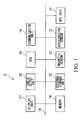
- FIG. 1 is a block diagram showing the constitution of a navigation device 1 in accordance with the preferred embodiment of the present invention.
- the navigation device 1 is constituted of a CPU 10, a GPS unit 11, an acceleration sensor 12, a magnetic sensor 13, a memory 14, an external storage unit 15, a communication unit 16, a display unit 17, and an audio output unit 18, all of which are interconnected via a bus line 19. All the constituent elements 11 to 18 are stored in a single housing, so that the navigation device 1 has portability and can be attached to the desired place of a vehicle (not shown). The following description is made on the presumption that the navigation device 1 is installed in the vehicle.
- the CPU 10 loads programs stored in the memory 14 so as to control the constituent elements 11 to 18 in accordance with programs.
- the CPU 10 performs a position calculation process (details of which will be described in conjunction with FIGS. 2 to 4 ) based on the output signals of the GPS unit 11, the acceleration sensor 12, and the magnetic sensor 13.
- the CPU 10 also performs information processing implementing navigation functions.
- the GPS unit 11 triangulates the latitude, longitude, and altitude (representing the present position of the vehicle) based on the Global Positioning System (GPS). In addition, the GPS unit 11 also calculates the running speed and running direction of the vehicle based on the latest position and the preceding position of the vehicle. The GPS unit 11 outputs various pieces of information representing the position, the running speed, and the running direction of the vehicle. The GPS unit 11 receives GPS signals from stationary satellites so as to perform calculations using reception times of GPS signals (which are counted by a time counter, not shown), thus determining the present position.
- GPS Global Positioning System
- the acceleration sensor 12 detects an acceleration applied to the vehicle (or the navigation device 1) so as to produce and output acceleration information to the CPU 10.
- the acceleration embraces an acceleration applied to the acceleration sensor 12 in an accelerated motion of the vehicle and a gravitational acceleration detected by the acceleration sensor 12 when the vehicle is inclined in position on the slope and the like.
- the acceleration sensor 12 is a two-axial acceleration sensor which detects acceleration components in two axial directions (which cross perpendicularly with each other). Specifically, one of the two axes (e.g. an x-axis and a y-axis) of the acceleration sensor 12 substantially matches the reference axis of the magnetic sensor 13.
- the CPU 10 receives the acceleration information including acceleration components in the x-y coordinates system with reference to the reference axis of the magnetic sensor 13. Acceleration components detected by the acceleration sensor 12 may include offset errors due to the gravitational acceleration which is inevitably detected by the acceleration sensor 12.
- the magnetic sensor 13 detects geomagnetism applied to the vehicle (or the navigation device 1) so as to calculate the bearing directed by the reference axis thereof, thus producing and outputting bearing information to the CPU 10.
- the following description is made on the presumption that the reference axis of the magnetic sensor 13 deviates from the front-forward direction of the vehicle by a certain angle. This is because the user may place the navigation device 1 having portability in the vehicle in a desired place and position.
- the magnetic sensor 13 it is possible to use either a two-axial magnetic sensor (for detecting magnetic components in two axes perpendicularly crossing each other) or a three-axial magnetic sensor (for detecting magnetic components in three axes perpendicularly crossing each other).
- two elements e.g. magnetoresistive elements
- the memory 14 is constituted of a ROM and a RAM.
- the ROM stores programs to be executed by the CPU 10.
- the RAM serves as a storage area for storing temporary data which is produced during the execution of programs.
- the external storage unit 15 is a large-scale storage unit such as a hard-disk drive, which stores map information necessary for navigation.
- the communication unit 16 establishes connection with the Internet via wireless communication so as to download the latest map information and the like, which is then stored in the external storage unit 15.
- the display unit 17 graphically displays the present position and bearing of the vehicle on the map so as to achieve the positional guidance by way of navigation functions executed by the CPU 10.
- the audio output device 18 performs audio guidance by generating vocalized sound (which may instruct the user or driver to turn at the intersection at the appropriate timing) using a speaker.
- FIG. 2 is a block diagram showing the constitution for implementing the position calculation process, which is constituted of an INS position calculation unit 101 (where "INS” stands for "Inertial Navigation System” constituted of the acceleration sensor 12 and the magnetic sensor 13), an optimum value estimation unit 102, a position correction unit 103, an acceleration offset calculation unit 104, and an acceleration determination unit 105.
- the INS position calculation unit 101 receives the output signals of the GPS unit 11 and the INS (i.e., the acceleration sensor 12 and the magnetic sensor 13).
- the CPU 10 executes programs read from the memory 14 so as to implement the functions of the constituent elements 101 to 105 shown in FIG. 2 .
- the INS position calculation unit 101 calculates the position P INS and the speed V INS of the vehicle based on the input values thereof.
- the INS position calculation unit 101 outputs the calculated values of the position P INS and the speed V INS to the optimum value estimation unit 102 and the position correction unit 103.
- aN and aE designate the latitude component and longitude component of the acceleration a+b
- VN INS and VE INS designate the latitude component and longitude component of the speed V INS
- PN INS and PE INS designate the latitude component and longitude component of the position P INS
- VN0 INS , VE0 INS , PN0 INS , and PE0 INS designate the previously calculated values of VN INS , VE INS , PN INS , and PE INS
- ⁇ t designates a lapsed time which elapses between the preceding calculation timing and the present calculation timing
- R designates the radius of the earth.
- ⁇ c designates the corrected value of the bearing ⁇ which is calculated in step S52 shown in FIG. 4 on the presumption that the reference axis of the magnetic sensor 13 deviates from the front-forward direction of the vehicle.
- the navigation device 1 determines that the vehicle is presently subj ected to accelerated motion based on the acceleration components aN and aE, wherein the INS position calculation unit 101 calculates the speed V INS and also calculates the position P INS based on the speed V INS .
- the navigation device 1 determines that the vehicle is presently subjected to uniform motion based on the previously calculated values of speeds VN0 INS and VE0 INS , wherein the INS position calculation unit 101 calculates the speed V INS and the position P INS .
- the vehicle performs uniform motion when it runs on a slope, for example; hence, even when an offset error is included in the acceleration a detected by the acceleration sensor 12, the INS position calculation unit 101 calculates the position of the vehicle on the presumption that the vehicle is presently subjected to uniform motion; thus, it is possible to calculate the position with high precision without being affected by the offset error.
- the optimum value estimation unit 102 and the acceleration offset calculation unit 104 may effectively operate so as to calculate the acceleration offset b, by which the offset error of the acceleration sensor 12 is corrected, whereby it is possible to precisely calculate the position P INS in accordance with the equations (1A) to (1F) in the first calculation mode even when the accelerations aN and aE have small values.
- the navigation device 1 automatically switches over the processing thereof to the second calculation mode in which the position P INS is calculated in accordance with the equations (2A) to (2E) on the presumption that the vehicle is subjected to uniform motion. This is a great significance of the present invention.
- the optimum value estimation unit 102 inputs the position P INS and the speed V INS from the INS position calculation unit 101 while inputting the position P INS and the speed V GPS from the GPS unit 11. Due to differences of principles of estimation, the position P INS and the speed V INS of the INS calculation unit 101 may differ from the position P GPS and the speed V GPS of the GPS unit 11; hence, all the values of P INS , V INS , P GPS , and V GPS have specific errors thereof.
- the optimum value estimation unit 102 is used to estimate values having high probabilities based on the input values thereof.
- the estimation of the optimum values ⁇ P and ⁇ V is performed by operations using a Karman's filter, details of which will be described later.
- the optimum value estimation unit 102 delivers the optimum values ⁇ P and ⁇ V (which are estimated as described above) to the position correction unit 103 and the acceleration offset calculation unit 104.
- the position correction unit 103 corrects the position P INS of the vehicle (output from the INS calculation unit 101) by use of the optimum value ⁇ P (output from the optimum value estimation unit 102) in accordance with an equation (3), thus producing the position P having a highest probability.
- P P INS + ⁇ P
- the position correction unit 103 provides the navigation software (executed by the CPU 10) with the position P representative of the present position of the vehicle.
- the acceleration offset calculation unit 104 calculates the acceleration offset b which is the correction value for correcting the offset error included in the acceleration a detected by the acceleration sensor 12.
- the acceleration offset calculation unit 104 outputs the acceleration offset b to the INS position calculation unit 101.
- An equation for calculating the acceleration offset b based on the optimum value ⁇ P (of the positional difference) is determined based on the following presumption.
- the optimum value ⁇ P of the optimum value estimation unit 102 should be zero. If the INS position calculation unit 101 does not completely correct the acceleration a of the acceleration sensor 12 so that some offset error may still remain, an imperfect value of acceleration offset (referred to as bc) may cause an error in the position P INS calculated by the INS position calculation unit 101, based on which the optimum value estimation unit 102 may erroneously produce the optimum value ⁇ P, which indicates a positional error caused by the uniformly accelerated motion of the vehicle at the acceleration bc and which is expressed by an equation (4).
- ⁇ ⁇ P 1 2 ⁇ bc ⁇ ⁇ ⁇ T 2
- acceleration offset calculation unit 104 calculates the acceleration offset b in accordance with an equation (5).
- b b ⁇ 0 + 2 ⁇ ⁇ Pxy ⁇ ⁇ T 2
- b0 indicates a preceding value of the acceleration offset which is used by the INS position calculation unit 101 in the preceding cycle of processing for correcting the acceleration a detected by the acceleration sensor 12;
- ⁇ T indicates a lapsed time between the preceding timing for correcting the acceleration and the present timing for correcting the acceleration;
- ⁇ Pxy designates a value produced by converting the optimum value ⁇ P (representative of the latitude and longitude output from the optimum value estimation unit 102) to suit the x-y coordinates system fixedly applied to the vehicle, wherein the ⁇ P is subjected to rotation of the bearing ⁇ so as to produce ⁇ Pxy.
- the acceleration offset calculation unit 104 calculates and outputs the acceleration offset b to the INS position calculation unit 101, which in turn corrects the acceleration a (detected by the acceleration sensor 12) by adding the acceleration offset b to the acceleration a in accordance with the equations (1A) and (1B).
- the navigation device 1 performs the aforementioned processing, in which the INS position calculation unit 101 corrects the acceleration a by use of the acceleration offset b calculated by the acceleration offset calculation unit 104, as necessary; hence, this processing can be omitted.
- the acceleration determination unit 105 (details of which will be described below) does not handle the acceleration a+b but the acceleration a. Due to the aforementioned processing, the acceleration a including the offset error is corrected; then, when the corrected value of the acceleration is smaller than the prescribed threshold, the position of the vehicle is calculated based on the presumption that the vehicle is subjected to uniform motion; hence, it is possible to calculate the position with a further high precision.
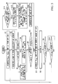
- step S1 the CPU 10 inputs the position P GPS , the speed V GPS , and the running direction ⁇ of the vehicle from the GPS unit 11 so as to store them in the memory 14.
- step S2 the CPU 10 inputs the acceleration a (including an offset error) from the acceleration sensor 12 and the bearing ⁇ of the reference axis of the magnetic sensor 13 so as to store them in the memory 14.
- step S3 the CPU 10 adds the acceleration offset b, which is stored in the memory 14 in advance, to the acceleration so as to produce the sum of acceleration a+b; then, it makes a decision as to whether or not the absolute value of a+b is above the prescribed threshold.
- step S 14 the acceleration offset b is set to a certain value calculated in step S 14; hence, the memory 14 stores it.
- step S4 the flow proceeds to step S4 in which the INS position calculation unit 101 calculates the position PINS and the speed VINS of the vehicle in accordance with the equations (1A) to (1F).
- step S5 the INS position calculation unit 101 calculates the position P INS and the speed V INS of the vehicle in accordance with the equations (2A) to (2E).
- step S3 it is possible to introduce an additional step prior to step S3 so as to evaluate the detection precision of the GPS unit 11, whereby the flow proceeds to step S3 only when the GPS unit 11 does not receive GPS signals or only when GPS signals do not have high precision, and whereby the flow proceeds to step S4 so as to calculate the position P INS and the speed V INS of the vehicle when GPS signals have high precision.
- step S4 so as to calculate the position P INS and the speed V INS of the vehicle when GPS signals have high precision.
- step S6 the CPU 10 makes a decision as to whether or not the position P GPS and the speed V GPS (output from the GPS unit 11) are updated.
- the step S1 is repeatedly executed with a certain time interval ⁇ T GPS
- the step S2 is repeatedly executed with another time interval ⁇ t INS ( ⁇ t GPS ); hence, before the lapse of the time interval ⁇ t GPS , the position P GPS and the speed V GPS are not updated, so that the decision result of step S6 is "NO".
- step S7 the position correction unit 103 corrects the position P INS (calculated in step S4 or step S5) by use of the newest optimum value ⁇ P stored in the memory 14, thus calculating the present position P of the vehicle having the highest probability.
- the optimum value ⁇ P is calculated in the preceding execution of step S 13 (which will be described below) and is stored in the memory 14 in advance.
- step S8 the position correction unit 103 provides the navigation software with the position P, which is produced by correcting the position P INS calculated by the INS position calculation unit 101.
- step S9 the CPU 10 makes a decision as to whether or not the time interval ⁇ t GPS has elapsed.
- the CPU 10 repeatedly executes the position calculation process of FIG. 3 starting from step S1.
- the flow proceeds to step S2 again so as to execute its following steps.
- the position P GPS and the speed V GPS output from the GPS unit 11 are updated with the time interval ⁇ t GPS
- the position P INS and the speed V INS calculated by the INS position calculation unit 101 are updated with the time interval ⁇ t INS .
- the time interval ⁇ t GPS is set to one second
- the time interval ⁇ t INS is set to 0.2 second.
- step S6 When the output data of the GPS unit 11 is updated, the decision result of step S6 turns to "YES" so that the flow proceeds to step S11 in which a decision is made as to whether or not the output data of the GPS unit 11 has adequately high precision.
- the CPU 10 determines that the GPS unit 11 has an adequately high precision when the speed V GPS is above a prescribed threshold.
- the difference ⁇ indicates how much the bearing ⁇ of the magnetic sensor 13 deviates from the running direction ⁇ of the vehicle.
- the estimated optimum values ⁇ P and ⁇ V are stored in the memory 14.
- the acceleration offset calculation unit 104 calculates the acceleration offset based on the optimum value ⁇ P.
- the acceleration offset b is stored in the memory 14 and is then used for the determination of the acceleration a+b compared with the prescribed threshold.
- step S14 the flow proceeds to step S7 in which the position correction unit 103 corrects the position P INS by use of the optimum value ⁇ P (which is estimated in step S 13) so as to calculate the present position P of the vehicle having the highest probability.
- step S11 When the CPU 10 determines in step S11 that the GPS 11 does not have an adequately high precision of detection, the flow directly proceeds to step S7 by skipping step S11, S12, S 13 (for estimation of the optimum values ⁇ P and ⁇ V), and step S 14 (for calculation of the acceleration offset b).
- step S7 This prevents the position correction unit 103 and the acceleration offset calculation unit 104 from erroneously calculating the position P and the acceleration offset b with low precision when the optimum value estimation unit 102 erroneously estimates the optimum value ⁇ P with low precision based on the output data of the GPS unit 11 having low precision.
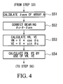
- step S5 the details of step S5 will be described with reference to the flowchart of FIG. 4 , in which the INS position calculation unit 101 calculates the position PINS and the speed VINS when the absolute value of the acceleration a+b is smaller than the prescribed threshold.
- step S51 the INS position calculation unit 101 calculates the average ⁇ ave among the values of the difference ⁇ which are stored in the array A in step S12 at different times.
- step S52 the INS position calculation unit 101 corrects the bearing ⁇ of the magnetic sensor 13 (which is acquired in step S2) by use of the average value ⁇ ave in accordance with an equation (6).
- ⁇ c ⁇ - ⁇ ave
- the bearing ⁇ is corrected to ⁇ c substantially representing the running direction of the vehicle; in other words, the running direction of the vehicle is determined based on the bearing ⁇ of the magnetic sensor 13.
- the INS position calculation unit 101 calculates the speed V INS by use of the corrected bearing ⁇ c in accordance with the equations (2B) and (2C).
- the INS calculation unit 101 calculates the position P INS in accordance with the equations (2D) and (2E).
- PN GPS and PE GPS designate the latitude and longitude components of the position P GPS output from the GPS unit 11, while VN GPS and VE GPS designate the latitude and longitude components of the speed V GPS output from the GPS unit 11.
- ⁇ PN and ⁇ PE designate the latitude and longitude components of the optimum v value ⁇ P
- ⁇ VN and ⁇ VE designate the latitude and longitude components of the optimum value ⁇ V.
- INS indicates the variables in connection with the inertial navigation system (INS).
- x k K k ⁇ z k
- ⁇ t designates a lapsed time between the preceding timing of correcting the acceleration using the acceleration offset b, which is calculated based on the optimum value ⁇ P produced by (k-1) times estimation, and the present timing of correcting the acceleration by way of k times estimation, wherein initial values of determinants R, P, and Q are expressed by equations (9) as follows:
- R 1.0 0 0 0 0 1.0 0 0 0 0.01 0 0 0 0 0.01
- the optimum value estimation unit 102 calculates the state vector x based on the detection vector z in accordance with the aforementioned equations.
- the calculated value of the state vector x indicates the latitude and longitude components of the optimum value ⁇ P and the latitude and longitude components of the optimum value ⁇ V.
- the present embodiment is preferably applicable to portable types of navigation devices but is also applicable to fixed types of navigation devices.
- vehicle may embrace automobiles, motorcycles, and bicycles.
- ⁇ Vxy is produced by converting the optimum value ⁇ V (constituted of the latitude and longitude components) to suit the x-y coordinates system (substantially matching the rotation of the bearing ⁇ ) fixedly applied to the vehicle.
- the detection vector and state vector x (which form the input and output of a Karman's filter used for estimation) are appropriately corrected, so that the optimum value of the position P (which is produced based on the calculated value of the state vector x) is directly provided to the navigation software (executed by the CPU 10).
- the acceleration (or deceleration) of a vehicle may is completed within a short time (e.g., several seconds) so that the acceleration (or deceleration) actually applied to a vehicle is varied rapidly in a short time, whereas the inclination (or slope) of a road on which the vehicle runs is not varied sharply, so that the acceleration (or deceleration) can be assumed as a constant value which may be maintained in a relatively long time.
- FIGS. 5A and 5B are graphs showing variations of the output of the acceleration sensor 12 in connection with an actual travel manner of a vehicle.
- FIG 5A shows an acceleration waveform "al" representing variations of the output of the acceleration sensor 12 due to the acceleration (or deceleration) applied to a vehicle, wherein the acceleration waveform al is greatly varied in level from a point pa to a point pb in a time tl.
- FIG. 5A shows an acceleration waveform "al" representing variations of the output of the acceleration sensor 12 due to the acceleration (or deceleration) applied to a vehicle, wherein the acceleration waveform al is greatly varied in level from a point pa to a point pb in a time tl.
- FIG. 5B shows an acceleration waveform "a2" representing variations of the output of the acceleration sensor 12 due to the inclination (or slope) of a road, wherein the acceleration waveform a2 is not substantially varied in a time t2 ranging from a point pc to a point pd.
- variations of acceleration greatly differ between the acceleration (or deceleration) of a vehicle and the inclination (or slope) of a road in a certain time.
- the navigation device 1 determines that the acceleration (or deceleration) is applied to a vehicle when the difference between the maximum value and the minimum value of the acceleration, i.e., variations of acceleration, are higher than a preset value, while it determines that the acceleration of a vehicle occurs due to the inclination (or slope) of the road when variations of acceleration are lower than the preset value, whereby it is possible to distinguish the acceleration of the vehicle from the inclination of the road.
- FIGS. 6A to 6C are used to explain the method how to calculate the acceleration offset based on the output of the acceleration sensor 12.
- the acceleration sensor 12 detects acceleration which is varied in accordance with an acceleration waveform A1 shown in FIG 6A .
- a low-pass filter (not shown) is used to suppress the short-period noise representing vibration components of the vehicle, thus producing a filter waveform B1 shown in FIG. 6B .
- the acceleration offset calculation unit 104 calculates an average value in a prescribed time as well as maximum and minimum values in the prescribed time with respect to acceleration. When the difference between the maximum value and the minimum value is higher than the preset value, the acceleration offset calculation unit 104 determines that the acceleration (or deceleration) is applied to the vehicle. When the difference between the maximum value and the minimum value is lower than the preset value, the acceleration offset calculation unit 104 determines that the acceleration (or deceleration) is not applied to the vehicle, but the vehicle is presently running on a road having a certain inclination (or a slope). With reference to the filter waveform B1, the acceleration offset calculation unit 104 detects the acceleration (or deceleration) in times ta and tc, while it detects the inclination (or slope) of the road in a time tb.
- the acceleration offset calculation unit 104 determines that the acceleration (or deceleration) is not applied to the vehicle, it sets the average value of acceleration as the acceleration offset, which is thus applied to calculations in the time tb.
- the acceleration offset calculation unit 104 determines that the acceleration (or deceleration) is applied to the vehicle, it maintains the previous value of the acceleration offset, so that the previous value of the acceleration offset is applied to calculations in the times ta and tc. Since the acceleration offset is not determined at time "0", it maintains the previous value of the acceleration offset, i.e. zero, in the time ta, while it maintains the latest value of the acceleration offset in the time tc.
- the acceleration offset calculation unit 104 calculates the acceleration offset in accordance with the aforementioned method, then, it outputs the acceleration offset to the INS position calculation unit 101.
- FIG. 6C shows an offset curve C1 representing variations of the acceleration offset calculated by the acceleration offset calculation unit 104.
- the acceleration offset calculation unit 104 is capable of precisely calculating the acceleration offset even when the GPS unit 11 cannot receive GPS signals, or even when GPS signals do not have an adequate level of reliability.
- the acceleration detected by the acceleration sensor 12 is varied due to a centrifugal force which occurs when the vehicle runs through a curved course of road.
- the acceleration offset calculation unit 104 calculates two components of the acceleration detected by the acceleration sensor 12, i.e., a first component of acceleration, which is applied in the direction corresponding to the corrected bearing ⁇ c (representing the running direction of the vehicle which is calculated in step S52), and a second component of acceleration, which is applied in the direction perpendicular to the corrected bearing ⁇ c; then, it determines that the detected acceleration depends upon the acceleration (or deceleration) of the vehicle in connection with the first component of acceleration, while it determines that the detected acceleration depends upon the curved course of road corresponding to the centrifugal force in connection with the second component of acceleration.
Landscapes
- Engineering & Computer Science (AREA)
- Radar, Positioning & Navigation (AREA)
- Remote Sensing (AREA)
- Physics & Mathematics (AREA)
- General Physics & Mathematics (AREA)
- Electromagnetism (AREA)
- Automation & Control Theory (AREA)
- Navigation (AREA)
Applications Claiming Priority (2)
| Application Number | Priority Date | Filing Date | Title |
|---|---|---|---|
| JP2007247783 | 2007-09-25 | ||
| JP2008218126A JP2009098127A (ja) | 2007-09-25 | 2008-08-27 | ナビゲーション装置 |
Publications (3)
| Publication Number | Publication Date |
|---|---|
| EP2042832A2 true EP2042832A2 (de) | 2009-04-01 |
| EP2042832A3 EP2042832A3 (de) | 2010-07-14 |
| EP2042832B1 EP2042832B1 (de) | 2014-09-17 |
Family
ID=40154059
Family Applications (1)
| Application Number | Title | Priority Date | Filing Date |
|---|---|---|---|
| EP08016699.4A Not-in-force EP2042832B1 (de) | 2007-09-25 | 2008-09-23 | Navigationsvorrichtung mit GPS Einheit, Beschleunigungs- und Richtungssensor |
Country Status (2)
| Country | Link |
|---|---|
| US (1) | US8108140B2 (de) |
| EP (1) | EP2042832B1 (de) |
Cited By (3)
| Publication number | Priority date | Publication date | Assignee | Title |
|---|---|---|---|---|
| EP2426514A1 (de) * | 2010-09-02 | 2012-03-07 | Casio Computer Co., Ltd. | Positionierungsvorrichtung und Positionierungsverfahren |
| JP2014528061A (ja) * | 2011-09-01 | 2014-10-23 | クアルコム,インコーポレイテッド | Mems加速度計の定期旅客機の離陸および着陸検出 |
| CN105407238A (zh) * | 2015-12-08 | 2016-03-16 | 北京百度网讯科技有限公司 | 一种基于传感器的骑行监测方法及装置 |
Families Citing this family (7)
| Publication number | Priority date | Publication date | Assignee | Title |
|---|---|---|---|---|
| EP2325605A1 (de) | 2009-11-24 | 2011-05-25 | Nederlandse Organisatie voor toegepast -natuurwetenschappelijk onderzoek TNO | Navigationssystem, Navigationsvorrichtung, Navigationsserver, mit einer Navigationsvorrichtung ausgestattetes Fahrzeug, eine Gruppe derartiger Fahrzeuge und Navigationsverfahren |
| JP2012185111A (ja) * | 2011-03-08 | 2012-09-27 | Seiko Epson Corp | 測位装置、測位方法 |
| JP5724676B2 (ja) * | 2011-06-27 | 2015-05-27 | 富士通株式会社 | 携帯端末装置、速度算出方法及び速度算出プログラム |
| WO2015057074A1 (en) * | 2013-10-18 | 2015-04-23 | Nederlandse Organisatie Voor Toegepast-Natuurwetenschappelijk Onderzoek Tno | Adjusted navigation |
| CN109459585B (zh) * | 2018-10-25 | 2021-02-09 | 北京航天计量测试技术研究所 | 一种加速度计零位偏置修正方法 |
| CN110568223B (zh) * | 2019-10-17 | 2021-12-07 | 上海三菱电梯有限公司 | 电机磁编码器检测系统 |
| US12094343B2 (en) | 2021-06-30 | 2024-09-17 | Textron Innovations Inc. | Vehicle access and fleet management control via Bluetooth beacons |
Citations (2)
| Publication number | Priority date | Publication date | Assignee | Title |
|---|---|---|---|---|
| JP2007247783A (ja) | 2006-03-16 | 2007-09-27 | Ntn Corp | ころ軸受の潤滑構造 |
| JP2008218126A (ja) | 2007-03-02 | 2008-09-18 | Sony Corp | 正極活物質の評価方法 |
Family Cites Families (9)
| Publication number | Priority date | Publication date | Assignee | Title |
|---|---|---|---|---|
| JPH0942979A (ja) | 1995-08-03 | 1997-02-14 | Alpine Electron Inc | 車載用ナビゲーション装置 |
| US5862511A (en) * | 1995-12-28 | 1999-01-19 | Magellan Dis, Inc. | Vehicle navigation system and method |
| JP4085463B2 (ja) | 1998-04-10 | 2008-05-14 | ソニー株式会社 | 速度計測方法および速度計測装置 |
| US6408245B1 (en) * | 2000-08-03 | 2002-06-18 | American Gnc Corporation | Filtering mechanization method of integrating global positioning system receiver with inertial measurement unit |
| US6622091B2 (en) * | 2001-05-11 | 2003-09-16 | Fibersense Technology Corporation | Method and system for calibrating an IG/GP navigational system |
| US6615135B2 (en) * | 2001-05-24 | 2003-09-02 | Prc Inc. | Satellite based on-board vehicle navigation system including predictive filtering and map-matching to reduce errors in a vehicular position |
| US6697736B2 (en) * | 2002-02-06 | 2004-02-24 | American Gnc Corporation | Positioning and navigation method and system thereof |
| JP4736866B2 (ja) * | 2005-04-28 | 2011-07-27 | 株式会社デンソー | ナビゲーション装置 |
| JP4816302B2 (ja) * | 2005-09-06 | 2011-11-16 | ソニー株式会社 | 加速度センサのオフセット検出装置、加速度センサのオフセット検出方法及び加速度センサのオフセット検出プログラム並びにナビゲーション装置 |
-
2008
- 2008-09-22 US US12/235,226 patent/US8108140B2/en not_active Expired - Fee Related
- 2008-09-23 EP EP08016699.4A patent/EP2042832B1/de not_active Not-in-force
Patent Citations (2)
| Publication number | Priority date | Publication date | Assignee | Title |
|---|---|---|---|---|
| JP2007247783A (ja) | 2006-03-16 | 2007-09-27 | Ntn Corp | ころ軸受の潤滑構造 |
| JP2008218126A (ja) | 2007-03-02 | 2008-09-18 | Sony Corp | 正極活物質の評価方法 |
Cited By (7)
| Publication number | Priority date | Publication date | Assignee | Title |
|---|---|---|---|---|
| EP2426514A1 (de) * | 2010-09-02 | 2012-03-07 | Casio Computer Co., Ltd. | Positionierungsvorrichtung und Positionierungsverfahren |
| CN102385050A (zh) * | 2010-09-02 | 2012-03-21 | 卡西欧计算机株式会社 | 测位装置及测位方法 |
| CN102385050B (zh) * | 2010-09-02 | 2013-10-23 | 卡西欧计算机株式会社 | 测位装置及测位方法 |
| US8855928B2 (en) | 2010-09-02 | 2014-10-07 | Casio Computer Co., Ltd. | Positioning apparatus judging movement method to control positioning timing |
| JP2014528061A (ja) * | 2011-09-01 | 2014-10-23 | クアルコム,インコーポレイテッド | Mems加速度計の定期旅客機の離陸および着陸検出 |
| CN105407238A (zh) * | 2015-12-08 | 2016-03-16 | 北京百度网讯科技有限公司 | 一种基于传感器的骑行监测方法及装置 |
| CN105407238B (zh) * | 2015-12-08 | 2018-11-02 | 北京百度网讯科技有限公司 | 一种基于传感器的骑行监测方法及装置 |
Also Published As
| Publication number | Publication date |
|---|---|
| US8108140B2 (en) | 2012-01-31 |
| EP2042832B1 (de) | 2014-09-17 |
| US20090082966A1 (en) | 2009-03-26 |
| EP2042832A3 (de) | 2010-07-14 |
Similar Documents
| Publication | Publication Date | Title |
|---|---|---|
| EP2042832B1 (de) | Navigationsvorrichtung mit GPS Einheit, Beschleunigungs- und Richtungssensor | |
| EP2040037A2 (de) | Navigationsvorrichtung | |
| US9494428B2 (en) | Attitude determination method, position calculation method, and attitude determination device | |
| US9273967B2 (en) | Bias estimating method, posture estimating method, bias estimating device, and posture estimating device | |
| JP5328252B2 (ja) | ナビゲーションシステムの位置検出装置および位置検出方法 | |
| US9448250B2 (en) | Detecting mount angle of mobile device in vehicle using motion sensors | |
| US10240931B2 (en) | System and method for navigation by applying corrected bias values to gyroscopic data | |
| EP2646777B1 (de) | Trägheitssensorgestützte kursrichtung und positionierung für gnss-fahrzeugnavigation | |
| EP0789223A1 (de) | Ortungsvorrichtung | |
| EP2034270A1 (de) | Haltungswinkelerfassungsvorrichtung und haltungswinkelerfassungsverfahren | |
| US20040172173A1 (en) | Mounting angle detection device | |
| US20200193740A1 (en) | Calibration method of the positioning of an onboard device for the acquisition and the remote transmission of data relating to motion and driving parameters of motor vehicles and motorcycles | |
| JP4941199B2 (ja) | ナビゲーション装置 | |
| JP3380404B2 (ja) | 移動検出装置 | |
| JP2004138553A (ja) | 移動体位置検出装置、移動体位置検出方法、プログラムおよび記録媒体 | |
| JP6383907B2 (ja) | 車輌位置計測装置及び方法 | |
| US20240191996A1 (en) | System and method for time synchronized fusion of multiple inertial sensors | |
| US9605958B2 (en) | Method and device for determining the inclined position of a vehicle | |
| JP2009098127A (ja) | ナビゲーション装置 | |
| JP4376738B2 (ja) | 角速度センサのゼロ点誤差検出装置および方法 | |
| KR20050049071A (ko) | 차량의 정지상태 판단방법과 이를 이용한 차량 항법정보생성방법 및 차량항법장치 | |
| JP4967724B2 (ja) | 現在地測位装置及び方法 | |
| US11548389B2 (en) | Control system and switch method for screen of vehicle | |
| JP4655901B2 (ja) | 移動体の水平走行判定装置及び方法 | |
| JP2008008653A (ja) | 取り付け方向判定方法、ナビゲーション装置及びプログラム |
Legal Events
| Date | Code | Title | Description |
|---|---|---|---|
| PUAI | Public reference made under article 153(3) epc to a published international application that has entered the european phase |
Free format text: ORIGINAL CODE: 0009012 |
|
| AK | Designated contracting states |
Kind code of ref document: A2 Designated state(s): AT BE BG CH CY CZ DE DK EE ES FI FR GB GR HR HU IE IS IT LI LT LU LV MC MT NL NO PL PT RO SE SI SK TR |
|
| AX | Request for extension of the european patent |
Extension state: AL BA MK RS |
|
| PUAL | Search report despatched |
Free format text: ORIGINAL CODE: 0009013 |
|
| AK | Designated contracting states |
Kind code of ref document: A3 Designated state(s): AT BE BG CH CY CZ DE DK EE ES FI FR GB GR HR HU IE IS IT LI LT LU LV MC MT NL NO PL PT RO SE SI SK TR |
|
| AX | Request for extension of the european patent |
Extension state: AL BA MK RS |
|
| RIC1 | Information provided on ipc code assigned before grant |
Ipc: G01C 21/16 20060101AFI20090109BHEP Ipc: G01S 5/14 20060101ALI20100608BHEP |
|
| 17P | Request for examination filed |
Effective date: 20100922 |
|
| 17Q | First examination report despatched |
Effective date: 20110118 |
|
| AKX | Designation fees paid |
Designated state(s): AT BE BG CH CY CZ DE DK EE ES FI FR GB GR HR HU IE IS IT LI LT LU LV MC MT NL NO PL PT RO SE SI SK TR |
|
| REG | Reference to a national code |
Ref country code: DE Ref legal event code: R079 Ref document number: 602008034412 Country of ref document: DE Free format text: PREVIOUS MAIN CLASS: G01C0021160000 Ipc: G01P0021000000 |
|
| GRAP | Despatch of communication of intention to grant a patent |
Free format text: ORIGINAL CODE: EPIDOSNIGR1 |
|
| RIC1 | Information provided on ipc code assigned before grant |
Ipc: G01C 21/16 20060101ALI20140218BHEP Ipc: G01S 19/49 20100101ALI20140218BHEP Ipc: G01P 21/00 20060101AFI20140218BHEP |
|
| INTG | Intention to grant announced |
Effective date: 20140314 |
|
| GRAS | Grant fee paid |
Free format text: ORIGINAL CODE: EPIDOSNIGR3 |
|
| GRAA | (expected) grant |
Free format text: ORIGINAL CODE: 0009210 |
|
| AK | Designated contracting states |
Kind code of ref document: B1 Designated state(s): AT BE BG CH CY CZ DE DK EE ES FI FR GB GR HR HU IE IS IT LI LT LU LV MC MT NL NO PL PT RO SE SI SK TR |
|
| REG | Reference to a national code |
Ref country code: GB Ref legal event code: FG4D |
|
| REG | Reference to a national code |
Ref country code: CH Ref legal event code: EP |
|
| REG | Reference to a national code |
Ref country code: IE Ref legal event code: FG4D |
|
| REG | Reference to a national code |
Ref country code: AT Ref legal event code: REF Ref document number: 687932 Country of ref document: AT Kind code of ref document: T Effective date: 20141015 |
|
| REG | Reference to a national code |
Ref country code: DE Ref legal event code: R096 Ref document number: 602008034412 Country of ref document: DE Effective date: 20141023 |
|
| PG25 | Lapsed in a contracting state [announced via postgrant information from national office to epo] |
Ref country code: SE Free format text: LAPSE BECAUSE OF FAILURE TO SUBMIT A TRANSLATION OF THE DESCRIPTION OR TO PAY THE FEE WITHIN THE PRESCRIBED TIME-LIMIT Effective date: 20140917 Ref country code: FI Free format text: LAPSE BECAUSE OF FAILURE TO SUBMIT A TRANSLATION OF THE DESCRIPTION OR TO PAY THE FEE WITHIN THE PRESCRIBED TIME-LIMIT Effective date: 20140917 Ref country code: LT Free format text: LAPSE BECAUSE OF FAILURE TO SUBMIT A TRANSLATION OF THE DESCRIPTION OR TO PAY THE FEE WITHIN THE PRESCRIBED TIME-LIMIT Effective date: 20140917 Ref country code: NO Free format text: LAPSE BECAUSE OF FAILURE TO SUBMIT A TRANSLATION OF THE DESCRIPTION OR TO PAY THE FEE WITHIN THE PRESCRIBED TIME-LIMIT Effective date: 20141217 Ref country code: GR Free format text: LAPSE BECAUSE OF FAILURE TO SUBMIT A TRANSLATION OF THE DESCRIPTION OR TO PAY THE FEE WITHIN THE PRESCRIBED TIME-LIMIT Effective date: 20141218 |
|
| REG | Reference to a national code |
Ref country code: NL Ref legal event code: VDEP Effective date: 20140917 |
|
| REG | Reference to a national code |
Ref country code: LT Ref legal event code: MG4D |
|
| PG25 | Lapsed in a contracting state [announced via postgrant information from national office to epo] |
Ref country code: LV Free format text: LAPSE BECAUSE OF FAILURE TO SUBMIT A TRANSLATION OF THE DESCRIPTION OR TO PAY THE FEE WITHIN THE PRESCRIBED TIME-LIMIT Effective date: 20140917 Ref country code: CY Free format text: LAPSE BECAUSE OF FAILURE TO SUBMIT A TRANSLATION OF THE DESCRIPTION OR TO PAY THE FEE WITHIN THE PRESCRIBED TIME-LIMIT Effective date: 20140917 Ref country code: HR Free format text: LAPSE BECAUSE OF FAILURE TO SUBMIT A TRANSLATION OF THE DESCRIPTION OR TO PAY THE FEE WITHIN THE PRESCRIBED TIME-LIMIT Effective date: 20140917 |
|
| REG | Reference to a national code |
Ref country code: AT Ref legal event code: MK05 Ref document number: 687932 Country of ref document: AT Kind code of ref document: T Effective date: 20140917 |
|
| PG25 | Lapsed in a contracting state [announced via postgrant information from national office to epo] |
Ref country code: NL Free format text: LAPSE BECAUSE OF FAILURE TO SUBMIT A TRANSLATION OF THE DESCRIPTION OR TO PAY THE FEE WITHIN THE PRESCRIBED TIME-LIMIT Effective date: 20140917 |
|
| PG25 | Lapsed in a contracting state [announced via postgrant information from national office to epo] |
Ref country code: CZ Free format text: LAPSE BECAUSE OF FAILURE TO SUBMIT A TRANSLATION OF THE DESCRIPTION OR TO PAY THE FEE WITHIN THE PRESCRIBED TIME-LIMIT Effective date: 20140917 Ref country code: EE Free format text: LAPSE BECAUSE OF FAILURE TO SUBMIT A TRANSLATION OF THE DESCRIPTION OR TO PAY THE FEE WITHIN THE PRESCRIBED TIME-LIMIT Effective date: 20140917 Ref country code: IS Free format text: LAPSE BECAUSE OF FAILURE TO SUBMIT A TRANSLATION OF THE DESCRIPTION OR TO PAY THE FEE WITHIN THE PRESCRIBED TIME-LIMIT Effective date: 20150117 Ref country code: RO Free format text: LAPSE BECAUSE OF FAILURE TO SUBMIT A TRANSLATION OF THE DESCRIPTION OR TO PAY THE FEE WITHIN THE PRESCRIBED TIME-LIMIT Effective date: 20140917 Ref country code: ES Free format text: LAPSE BECAUSE OF FAILURE TO SUBMIT A TRANSLATION OF THE DESCRIPTION OR TO PAY THE FEE WITHIN THE PRESCRIBED TIME-LIMIT Effective date: 20140917 Ref country code: SK Free format text: LAPSE BECAUSE OF FAILURE TO SUBMIT A TRANSLATION OF THE DESCRIPTION OR TO PAY THE FEE WITHIN THE PRESCRIBED TIME-LIMIT Effective date: 20140917 Ref country code: PT Free format text: LAPSE BECAUSE OF FAILURE TO SUBMIT A TRANSLATION OF THE DESCRIPTION OR TO PAY THE FEE WITHIN THE PRESCRIBED TIME-LIMIT Effective date: 20150119 |
|
| REG | Reference to a national code |
Ref country code: CH Ref legal event code: PL |
|
| PG25 | Lapsed in a contracting state [announced via postgrant information from national office to epo] |
Ref country code: AT Free format text: LAPSE BECAUSE OF FAILURE TO SUBMIT A TRANSLATION OF THE DESCRIPTION OR TO PAY THE FEE WITHIN THE PRESCRIBED TIME-LIMIT Effective date: 20140917 Ref country code: PL Free format text: LAPSE BECAUSE OF FAILURE TO SUBMIT A TRANSLATION OF THE DESCRIPTION OR TO PAY THE FEE WITHIN THE PRESCRIBED TIME-LIMIT Effective date: 20140917 |
|
| REG | Reference to a national code |
Ref country code: IE Ref legal event code: MM4A |
|
| REG | Reference to a national code |
Ref country code: DE Ref legal event code: R097 Ref document number: 602008034412 Country of ref document: DE |
|
| REG | Reference to a national code |
Ref country code: FR Ref legal event code: PLFP Year of fee payment: 8 |
|
| PG25 | Lapsed in a contracting state [announced via postgrant information from national office to epo] |
Ref country code: MC Free format text: LAPSE BECAUSE OF FAILURE TO SUBMIT A TRANSLATION OF THE DESCRIPTION OR TO PAY THE FEE WITHIN THE PRESCRIBED TIME-LIMIT Effective date: 20140917 Ref country code: BE Free format text: LAPSE BECAUSE OF NON-PAYMENT OF DUE FEES Effective date: 20140930 |
|
| PLBE | No opposition filed within time limit |
Free format text: ORIGINAL CODE: 0009261 |
|
| STAA | Information on the status of an ep patent application or granted ep patent |
Free format text: STATUS: NO OPPOSITION FILED WITHIN TIME LIMIT |
|
| PG25 | Lapsed in a contracting state [announced via postgrant information from national office to epo] |
Ref country code: DK Free format text: LAPSE BECAUSE OF FAILURE TO SUBMIT A TRANSLATION OF THE DESCRIPTION OR TO PAY THE FEE WITHIN THE PRESCRIBED TIME-LIMIT Effective date: 20140917 Ref country code: CH Free format text: LAPSE BECAUSE OF NON-PAYMENT OF DUE FEES Effective date: 20140930 Ref country code: LI Free format text: LAPSE BECAUSE OF NON-PAYMENT OF DUE FEES Effective date: 20140930 |
|
| 26N | No opposition filed |
Effective date: 20150618 |
|
| PG25 | Lapsed in a contracting state [announced via postgrant information from national office to epo] |
Ref country code: IT Free format text: LAPSE BECAUSE OF FAILURE TO SUBMIT A TRANSLATION OF THE DESCRIPTION OR TO PAY THE FEE WITHIN THE PRESCRIBED TIME-LIMIT Effective date: 20140917 Ref country code: IE Free format text: LAPSE BECAUSE OF NON-PAYMENT OF DUE FEES Effective date: 20140923 |
|
| PGFP | Annual fee paid to national office [announced via postgrant information from national office to epo] |
Ref country code: DE Payment date: 20150916 Year of fee payment: 8 Ref country code: GB Payment date: 20150923 Year of fee payment: 8 |
|
| PG25 | Lapsed in a contracting state [announced via postgrant information from national office to epo] |
Ref country code: SI Free format text: LAPSE BECAUSE OF FAILURE TO SUBMIT A TRANSLATION OF THE DESCRIPTION OR TO PAY THE FEE WITHIN THE PRESCRIBED TIME-LIMIT Effective date: 20140917 |
|
| PGFP | Annual fee paid to national office [announced via postgrant information from national office to epo] |
Ref country code: FR Payment date: 20150629 Year of fee payment: 8 |
|
| PG25 | Lapsed in a contracting state [announced via postgrant information from national office to epo] |
Ref country code: BG Free format text: LAPSE BECAUSE OF FAILURE TO SUBMIT A TRANSLATION OF THE DESCRIPTION OR TO PAY THE FEE WITHIN THE PRESCRIBED TIME-LIMIT Effective date: 20140917 |
|
| PG25 | Lapsed in a contracting state [announced via postgrant information from national office to epo] |
Ref country code: MT Free format text: LAPSE BECAUSE OF FAILURE TO SUBMIT A TRANSLATION OF THE DESCRIPTION OR TO PAY THE FEE WITHIN THE PRESCRIBED TIME-LIMIT Effective date: 20140917 |
|
| PG25 | Lapsed in a contracting state [announced via postgrant information from national office to epo] |
Ref country code: LU Free format text: LAPSE BECAUSE OF NON-PAYMENT OF DUE FEES Effective date: 20140923 Ref country code: HU Free format text: LAPSE BECAUSE OF FAILURE TO SUBMIT A TRANSLATION OF THE DESCRIPTION OR TO PAY THE FEE WITHIN THE PRESCRIBED TIME-LIMIT; INVALID AB INITIO Effective date: 20080923 Ref country code: TR Free format text: LAPSE BECAUSE OF FAILURE TO SUBMIT A TRANSLATION OF THE DESCRIPTION OR TO PAY THE FEE WITHIN THE PRESCRIBED TIME-LIMIT Effective date: 20140917 |
|
| REG | Reference to a national code |
Ref country code: DE Ref legal event code: R119 Ref document number: 602008034412 Country of ref document: DE |
|
| GBPC | Gb: european patent ceased through non-payment of renewal fee |
Effective date: 20160923 |
|
| REG | Reference to a national code |
Ref country code: FR Ref legal event code: ST Effective date: 20170531 |
|
| PG25 | Lapsed in a contracting state [announced via postgrant information from national office to epo] |
Ref country code: GB Free format text: LAPSE BECAUSE OF NON-PAYMENT OF DUE FEES Effective date: 20160923 Ref country code: DE Free format text: LAPSE BECAUSE OF NON-PAYMENT OF DUE FEES Effective date: 20170401 Ref country code: FR Free format text: LAPSE BECAUSE OF NON-PAYMENT OF DUE FEES Effective date: 20160930 |