EP2042808A2 - Fuel nozzle of gas turbine combustor for DME and design method thereof - Google Patents
Fuel nozzle of gas turbine combustor for DME and design method thereof Download PDFInfo
- Publication number
- EP2042808A2 EP2042808A2 EP08157941A EP08157941A EP2042808A2 EP 2042808 A2 EP2042808 A2 EP 2042808A2 EP 08157941 A EP08157941 A EP 08157941A EP 08157941 A EP08157941 A EP 08157941A EP 2042808 A2 EP2042808 A2 EP 2042808A2
- Authority
- EP
- European Patent Office
- Prior art keywords
- dme
- fuel
- gas turbine
- turbine combustor
- injection
- Prior art date
- Legal status (The legal status is an assumption and is not a legal conclusion. Google has not performed a legal analysis and makes no representation as to the accuracy of the status listed.)
- Granted
Links
Images

Classifications
-
- F—MECHANICAL ENGINEERING; LIGHTING; HEATING; WEAPONS; BLASTING
- F02—COMBUSTION ENGINES; HOT-GAS OR COMBUSTION-PRODUCT ENGINE PLANTS
- F02C—GAS-TURBINE PLANTS; AIR INTAKES FOR JET-PROPULSION PLANTS; CONTROLLING FUEL SUPPLY IN AIR-BREATHING JET-PROPULSION PLANTS
- F02C7/00—Features, components parts, details or accessories, not provided for in, or of interest apart form groups F02C1/00 - F02C6/00; Air intakes for jet-propulsion plants
- F02C7/22—Fuel supply systems
-
- F—MECHANICAL ENGINEERING; LIGHTING; HEATING; WEAPONS; BLASTING
- F23—COMBUSTION APPARATUS; COMBUSTION PROCESSES
- F23R—GENERATING COMBUSTION PRODUCTS OF HIGH PRESSURE OR HIGH VELOCITY, e.g. GAS-TURBINE COMBUSTION CHAMBERS
- F23R3/00—Continuous combustion chambers using liquid or gaseous fuel
- F23R3/28—Continuous combustion chambers using liquid or gaseous fuel characterised by the fuel supply
- F23R3/286—Continuous combustion chambers using liquid or gaseous fuel characterised by the fuel supply having fuel-air premixing devices
-
- F—MECHANICAL ENGINEERING; LIGHTING; HEATING; WEAPONS; BLASTING
- F01—MACHINES OR ENGINES IN GENERAL; ENGINE PLANTS IN GENERAL; STEAM ENGINES
- F01D—NON-POSITIVE DISPLACEMENT MACHINES OR ENGINES, e.g. STEAM TURBINES
- F01D9/00—Stators
- F01D9/02—Nozzles; Nozzle boxes; Stator blades; Guide conduits, e.g. individual nozzles
-
- F—MECHANICAL ENGINEERING; LIGHTING; HEATING; WEAPONS; BLASTING
- F23—COMBUSTION APPARATUS; COMBUSTION PROCESSES
- F23R—GENERATING COMBUSTION PRODUCTS OF HIGH PRESSURE OR HIGH VELOCITY, e.g. GAS-TURBINE COMBUSTION CHAMBERS
- F23R3/00—Continuous combustion chambers using liquid or gaseous fuel
- F23R3/02—Continuous combustion chambers using liquid or gaseous fuel characterised by the air-flow or gas-flow configuration
- F23R3/04—Air inlet arrangements
- F23R3/10—Air inlet arrangements for primary air
- F23R3/12—Air inlet arrangements for primary air inducing a vortex
Definitions
- the present invention relates to a fuel nozzle of a gas turbine combustor for dimethyl ether (DME, CH 3 OCH 3 ) and a design method thereof. More particularly, the present invention relates to a fuel nozzle of a gas turbine combustor for DME and a design method thereof that can obtain optimal combustion of DME in the gas turbine combustor, thereby achieving cost reduction of power plants, enhancement in reliability of the power plants, and diversification of usable fuel.
- DME dimethyl ether
- dimethyl ether As is well known in the related art, dimethyl ether (DME) has recently been in the spotlight as a new clean fuel since it can be produced from various raw materials such as natural gas, coal, coal bed methane, etc., permits convenient transportation and storage like Liquefied Petroleum Gas (LPG), and has good exhaust characteristics.
- DME dimethyl ether
- DME has a lower heating value, a higher combustion rate and a lower ignition temperature than those of natural gas used as the primary fuel for gas turbines. Therefore, if DME is directly applied to existing combustors, the combustor is likely to experience damage due to liquefaction and combustion oscillation.
- DME has a high combustion velocity and a low ignition temperature
- a combustor is likely to experience damage caused by flame back when it is used in the gas turbine.
- DME has a low heating value, 28.8MJ/kg (59.3 MJ/Nm 3 ), which is lower than the heating value of natural gas, 49.0MJ/kg (35.9 MJ/Nm 3 ), modification of the combustor is required.
- DME has been studied as an alternative to diesel fuel, and many patents and papers designing a fuel supply system and remodeling the combustor have proposed to provide a diesel vehicle capable of using DME.
- development of a fuel nozzle of a gas turbine for DME has yet to be proposed.
- a combustor according to the present invention is expected to enhance utility and reliability of a power plant through stable operation of a power plant running on DME, while reducing power generation costs with DME.
- the present invention provides a fuel nozzle of a gas turbine combustor for DME and a design method thereof that can obtain optimal combustion of DME in a gas turbine of a power plant, thereby achieving cost reduction of power plants, enhancement in reliability of the power plants, and diversification of usable fuel.
- Fig. 1 is a perspective view of a fuel nozzle of a gas turbine combustor for dimethyl ether (DME) according to one embodiment of the present invention
- Fig. 2 is a partially cut-away perspective view of the fuel nozzle shown in Fig. 1
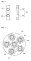
- Fig. 3 is enlarged front and sectional views taken along line I-I in Fig. 2
- Fig. 4 is a front view of a multi-cup combustor including a plurality of fuel nozzles of the gas turbine combustor for DME according to the embodiment of the present invention.
- Fig. 1 is a perspective view of a fuel nozzle of a gas turbine combustor for dimethyl ether (DME) according to one embodiment of the present invention
- Fig. 2 is a partially cut-away perspective view of the fuel nozzle shown in Fig. 1 .
- DME dimethyl ether
- a fuel nozzle of a gas turbine combustor according to the present invention includes a pilot fuel injection hole 105 at the center thereof and a plurality of fuel injection ports 108 disposed at equiangular positions around the pilot fuel injection hole 105 to inject DME.
- Each of the fuel injection ports 108 includes a pair of upper and lower DME injection orifices 102 and 103 that communicate with a fuel-air mixture injection swirler 104. Further, the upper DME injection orifice 102 becomes gradually wider, but the DME lower injection hole 103 becomes gradually narrower.
- the foregoing fuel nozzle is designed as follows. 1. Design method
- Wobbe indexes that indicate energy of heat input to the combustor are calculated.
- the Wobbe index is expressed as a function of a heating value and a specific gravity.
- WI Q d
- Q lower heating value (kcal/Nm 3 )
- d specific gravity of gas at 0°C and 1atm.
- the heat inputs of natural gas (N.G.) and DME are calculated by the following Equations 3 and 4.
- Naturel Gas Heat Input : I N . G . 0.011 ⁇ D N . G . 2 ⁇ K ⁇ p N . G . ⁇ WI N . G .
- the enlarging ratio, 1.086, of the fuel injection port has to be calculated from the measured heating values of natural gas and DME, and the enlarging ratio may be designed in the range of 105 ⁇ 150% according to change in the physical properties of natural gas and DME.
- Table 1 Physical properties of natural gas and DME Natural gas DME Heating Value [kcal/Nm 3 ] 10,500 14,164 Specific Gravity (vs. air) 0.625 1.586 Wobbe Index 13,281 11,247
- the total area of the fuel injection port 108 having the upper and lower DME injection orifices 102 and 103 is designed to be larger by 105 ⁇ 150% than that of the conventional natural gas combustor.
- the fuel injection port 108 is designed to meet the following conditions 1, 2 and 3.
- the present invention proposes the method of designing the fuel nozzle which is considered as an important factor in redesigning a gas turbine combustor for natural gas into a gas turbine combustor for DME.
- the present invention enables stable operation of the gas turbine combustor for DME with improved combustion efficiency and reduced amounts of harmful gases such as NO x or the like.
- the present invention promotes utility of DME as a fuel for power plants while achieving cost reduction of the power plants, enhancement in reliability of the power plants, and diversification of usable fuels.
Landscapes
- Engineering & Computer Science (AREA)
- Chemical & Material Sciences (AREA)
- Combustion & Propulsion (AREA)
- Mechanical Engineering (AREA)
- General Engineering & Computer Science (AREA)
- Gas Burners (AREA)
Abstract
Description
- The present invention relates to a fuel nozzle of a gas turbine combustor for dimethyl ether (DME, CH3OCH3) and a design method thereof. More particularly, the present invention relates to a fuel nozzle of a gas turbine combustor for DME and a design method thereof that can obtain optimal combustion of DME in the gas turbine combustor, thereby achieving cost reduction of power plants, enhancement in reliability of the power plants, and diversification of usable fuel.
- As is well known in the related art, dimethyl ether (DME) has recently been in the spotlight as a new clean fuel since it can be produced from various raw materials such as natural gas, coal, coal bed methane, etc., permits convenient transportation and storage like Liquefied Petroleum Gas (LPG), and has good exhaust characteristics.
- Generally, DME has a lower heating value, a higher combustion rate and a lower ignition temperature than those of natural gas used as the primary fuel for gas turbines. Therefore, if DME is directly applied to existing combustors, the combustor is likely to experience damage due to liquefaction and combustion oscillation.
- For example, when DME is applied to a dry low NOx gas turbine combustor, there are problems of flame back, combustion oscillation, combustion instability, etc. due to the high combustion velocity and the low ignition temperature.
- In a general power plant using a gas turbine, natural gas containing as much as 85% or more methane (CH4) is used as a primary fuel while oil distillates are used as a back up fuel. However, market prices of such fuel are volatile. To cope with the volatile market price of the fuel, there is a need to develop a gas turbine capable of employing diverse fuels for the power plants. Particularly, a new fuel, e.g., dimethyl ether (DME) produced from various raw materials such as natural gas, coal, biomass, etc. by a chemical process will be used in the future in consideration of economical and technical efficiency.
- However, since DME has a high combustion velocity and a low ignition temperature, a combustor is likely to experience damage caused by flame back when it is used in the gas turbine. Further, since DME has a low heating value, 28.8MJ/kg (59.3 MJ/Nm3), which is lower than the heating value of natural gas, 49.0MJ/kg (35.9 MJ/Nm3), modification of the combustor is required.
- In view of the combustion properties of DME having a high cetane number, DME has been studied as an alternative to diesel fuel, and many patents and papers designing a fuel supply system and remodeling the combustor have proposed to provide a diesel vehicle capable of using DME. However, development of a fuel nozzle of a gas turbine for DME has yet to be proposed.
- A combustor according to the present invention is expected to enhance utility and reliability of a power plant through stable operation of a power plant running on DME, while reducing power generation costs with DME.
- Accordingly, the present invention provides a fuel nozzle of a gas turbine combustor for DME and a design method thereof that can obtain optimal combustion of DME in a gas turbine of a power plant, thereby achieving cost reduction of power plants, enhancement in reliability of the power plants, and diversification of usable fuel.
-
Fig. 1 is a perspective view of a fuel nozzle of a gas turbine combustor for dimethyl ether (DME) according to one embodiment of the present invention;Fig. 2 is a partially cut-away perspective view of the fuel nozzle shown inFig. 1 ;Fig. 3 is enlarged front and sectional views taken along line I-I inFig. 2 ; andFig. 4 is a front view of a multi-cup combustor including a plurality of fuel nozzles of the gas turbine combustor for DME according to the embodiment of the present invention. - Exemplary embodiments of the present invention will be described in detail with reference to the accompanying drawings hereinafter.
-
Fig. 1 is a perspective view of a fuel nozzle of a gas turbine combustor for dimethyl ether (DME) according to one embodiment of the present invention, andFig. 2 is a partially cut-away perspective view of the fuel nozzle shown inFig. 1 . - A fuel nozzle of a gas turbine combustor according to the present invention includes a pilot
fuel injection hole 105 at the center thereof and a plurality offuel injection ports 108 disposed at equiangular positions around the pilotfuel injection hole 105 to inject DME. Each of thefuel injection ports 108 includes a pair of upper and lowerDME injection orifices mixture injection swirler 104. Further, the upperDME injection orifice 102 becomes gradually wider, but the DMElower injection hole 103 becomes gradually narrower. - The foregoing fuel nozzle is designed as follows. 1. Design method
- With regard to a conventional natural gas combustor and a DME combustor, Wobbe indexes that indicate energy of heat input to the combustor are calculated.
- As shown in Equation 1, the Wobbe index is expressed as a function of a heating value and a specific gravity.

WI: Wobbe Index
Q: lower heating value (kcal/Nm3)
d: specific gravity of gas at 0°C and 1atm. - Under a condition of equalizing heat input on the basis of the Wobbe index obtained in the first step, the minimum cross-section sum of the fuel injection ports is calculated. (Here, the fuel gas injection pressure (P) has to be equally applied. This is because an increase in fuel has injection pressure leads to change in fuel injection distance and generates nitrogen oxides (NOx) due to incomplete combustion and diffusion combustion.)

I: heat input (kcal/hr)
D: diameter (mm) of nozzle
K: flux coefficient (about 0.8), constant
P: injection pressure of fuel gas (mmH2O)
WI: Wobbe index - The heat inputs of natural gas (N.G.) and DME are calculated by the following Equations 3 and 4.


- Further, the above equations are rearranged into Equation 6 by substituting Equations 3 and 4 into Equation 5 and using physical properties in Table 1.

- However, the enlarging ratio, 1.086, of the fuel injection port has to be calculated from the measured heating values of natural gas and DME, and the enlarging ratio may be designed in the range of 105 ∼ 150% according to change in the physical properties of natural gas and DME.
Table 1: Physical properties of natural gas and DME Natural gas DME Heating Value [kcal/Nm3] 10,500 14,164 Specific Gravity (vs. air) 0.625 1.586 Wobbe Index 13,281 11,247 - In the
fuel nozzle 101 according to the present invention, the total area of thefuel injection port 108 having the upper and lowerDME injection orifices - To enhance combustion performance such as NOx reduction, combustion efficiency, flame-back prevention, etc. under the same heat input condition, the
fuel injection port 108 is designed to meet the following conditions ①, ② and ③. - The same heat input could be accomplished when changing only the diameter of the fuel injection port with the resultant value obtained in the second step, but experimental results showed that NOx increases but combustion efficiency decreases. To complement these results, the number of
fuel injection ports 108 is increased and the fuel injection ports are positioned uniformly in upper and lower streams. Consequently, the combustion efficiency can be increased due to prevention of flame back and a sufficient increase in mixture ratio of fuel and air. - ① To ensure swirling flow and uniform distribution of fuel, the
fuel nozzle 101 of the present invention is designed to have thefuel injection ports 108 each divided into the upperDME injection orifice 102 at an upper stream and the lowerDME injection orifice 103 at a lower stream, in which the minimum cross-section sum of totalfuel injection ports 108 is equal to
- ② The upper DME injection orifice 102: since the
fuel injection port 108 is disposed near a combustion chamber, it is necessary to maintain a smooth surface for the purpose of preventing separation of a flow to reduce combustion oscillation and to distribute the fuel uniformly. Accordingly, the upperDME injection orifice 102 is designed to have a channel that becomes gradually wider toward an outlet of fuel. - ③ The lower DME injection orifice 103: since the
fuel injection port 108 is farther apart from the combustion chamber than the upperDME injection orifice 102, it has a longer fuel injection distance toward air than the upperDME injection orifice 102, and thus, it is necessary to have a regular jet shape. Accordingly, the lowerDME injection orifice 102 is designed to have a channel tapered toward an outlet of the fuel. - As described above, the present invention proposes the method of designing the fuel nozzle which is considered as an important factor in redesigning a gas turbine combustor for natural gas into a gas turbine combustor for DME. The present invention enables stable operation of the gas turbine combustor for DME with improved combustion efficiency and reduced amounts of harmful gases such as NOx or the like.
- Accordingly, the present invention promotes utility of DME as a fuel for power plants while achieving cost reduction of the power plants, enhancement in reliability of the power plants, and diversification of usable fuels.
- Although the present invention has been described with reference to the embodiments and the accompanying drawings, the invention is not limited to the embodiments and the drawings. It should be understood that various modifications and changes can be made by those skilled in the art without departing from the spirit and scope of the present invention as defined by the accompanying claims.
Claims (3)
- A fuel nozzle of a gas turbine combustor for dimethyl ether (DME) comprising a pilot fuel injection hole formed at the center of the nozzle and a plurality of fuel injection ports formed at equiangular positions around the pilot fuel injection hole to inject DME,
wherein
each of the fuel injection ports comprises a pair of upper and lower DME injection orifices communicating with a fuel-air mixture injection swirler, and the upper DME injection orifice becomes gradually wider, whereas the lower DME injection orifice becomes gradually narrower. - The fuel nozzle according to claim 1 being provided in plural to constitute a multi-cup gas turbine combustor.
- A method of designing a fuel nozzle of a gas turbine combustor for dimethyl ether (DME) to have fuel injection ports, each comprising a pair of upper and lower DME injection orifices respectively disposed at upper and lower streams,
wherein a total area of the fuel injection ports is designed to be 105 ∼ 150% larger than that of a gas turbine combustor for natural gas, and the number of fuel injection ports is designed to be more than that of the gas turbine combustor for natural gas.
Applications Claiming Priority (1)
| Application Number | Priority Date | Filing Date | Title |
|---|---|---|---|
| KR1020070097756A KR100872841B1 (en) | 2007-09-28 | 2007-09-28 | Fuel Nozzle of DM Gas Fuel Combustor and Its Design Method |
Publications (3)
| Publication Number | Publication Date |
|---|---|
| EP2042808A2 true EP2042808A2 (en) | 2009-04-01 |
| EP2042808A3 EP2042808A3 (en) | 2014-02-12 |
| EP2042808B1 EP2042808B1 (en) | 2015-08-05 |
Family
ID=40342173
Family Applications (1)
| Application Number | Title | Priority Date | Filing Date |
|---|---|---|---|
| EP08157941.9A Active EP2042808B1 (en) | 2007-09-28 | 2008-06-10 | Fuel nozzle of gas turbine combustor for DME. |
Country Status (5)
| Country | Link |
|---|---|
| US (1) | US8132415B2 (en) |
| EP (1) | EP2042808B1 (en) |
| JP (1) | JP4603602B2 (en) |
| KR (1) | KR100872841B1 (en) |
| CN (1) | CN101398185B (en) |
Families Citing this family (6)
| Publication number | Priority date | Publication date | Assignee | Title |
|---|---|---|---|---|
| KR101024321B1 (en) * | 2008-10-31 | 2011-03-23 | 한국전력공사 | Gas turbine combustor for coal gas |
| US8479519B2 (en) * | 2009-01-07 | 2013-07-09 | General Electric Company | Method and apparatus to facilitate cooling of a diffusion tip within a gas turbine engine |
| US20130298563A1 (en) * | 2012-05-14 | 2013-11-14 | General Electric Company | Secondary Combustion System |
| KR101674311B1 (en) | 2015-08-06 | 2016-11-08 | 한국에너지기술연구원 | High velocity jet gas burner with fuel-oxidant mixing and combustion control |
| FR3043173B1 (en) * | 2015-10-29 | 2017-12-22 | Snecma | AERODYNAMIC INJECTION SYSTEM FOR AIRCRAFT TURBOMACHINE WITH IMPROVED AIR / FUEL MIXTURE |
| JP6626743B2 (en) * | 2016-03-03 | 2019-12-25 | 三菱重工業株式会社 | Combustion device and gas turbine |
Family Cites Families (17)
| Publication number | Priority date | Publication date | Assignee | Title |
|---|---|---|---|---|
| DE3317035A1 (en) * | 1983-05-10 | 1984-11-15 | BBC Aktiengesellschaft Brown, Boveri & Cie., Baden, Aargau | MULTIPLE BURNER |
| US5492277A (en) * | 1993-02-17 | 1996-02-20 | Nippondenso Co., Ltd. | Fluid injection nozzle |
| JPH08261466A (en) * | 1995-12-18 | 1996-10-11 | Hitachi Ltd | Gas turbine combustor |
| JP3300754B2 (en) | 1998-02-09 | 2002-07-08 | 三菱重工業株式会社 | Combustor |
| DE19925380A1 (en) * | 1999-06-02 | 2000-12-07 | Volkswagen Ag | Fuel injection valve for internal combustion engines |
| US6983605B1 (en) * | 2000-04-07 | 2006-01-10 | General Electric Company | Methods and apparatus for reducing gas turbine engine emissions |
| JP4604269B2 (en) * | 2001-08-08 | 2011-01-05 | パロマ工業株式会社 | Gas burning appliances |
| US6928823B2 (en) * | 2001-08-29 | 2005-08-16 | Hitachi, Ltd. | Gas turbine combustor and operating method thereof |
| US6691516B2 (en) * | 2002-07-15 | 2004-02-17 | Power Systems Mfg, Llc | Fully premixed secondary fuel nozzle with improved stability |
| US6871488B2 (en) * | 2002-12-17 | 2005-03-29 | Pratt & Whitney Canada Corp. | Natural gas fuel nozzle for gas turbine engine |
| JP4222962B2 (en) * | 2004-03-30 | 2009-02-12 | 大阪瓦斯株式会社 | Burner device and gas turbine engine |
| US7251940B2 (en) * | 2004-04-30 | 2007-08-07 | United Technologies Corporation | Air assist fuel injector for a combustor |
| US6983600B1 (en) * | 2004-06-30 | 2006-01-10 | General Electric Company | Multi-venturi tube fuel injector for gas turbine combustors |
| US7377036B2 (en) * | 2004-10-05 | 2008-05-27 | General Electric Company | Methods for tuning fuel injection assemblies for a gas turbine fuel nozzle |
| JP4728176B2 (en) * | 2005-06-24 | 2011-07-20 | 株式会社日立製作所 | Burner, gas turbine combustor and burner cooling method |
| GB2443429A (en) * | 2005-09-24 | 2008-05-07 | Siemens Ind Turbomachinery Ltd | Fuel Vaporisation Within a Burner Associated With a Combustion Chamber |
| KR100716889B1 (en) | 2006-05-18 | 2007-05-09 | 한국전력공사 | Variable Fuel Nozzle for Firing Position of Dry Low NOx Gas Turbine Combustor for Power Generation |
-
2007
- 2007-09-28 KR KR1020070097756A patent/KR100872841B1/en active Active
-
2008
- 2008-06-10 EP EP08157941.9A patent/EP2042808B1/en active Active
- 2008-06-24 CN CN2008101268303A patent/CN101398185B/en active Active
- 2008-06-24 JP JP2008164816A patent/JP4603602B2/en active Active
- 2008-06-25 US US12/215,159 patent/US8132415B2/en active Active
Also Published As
| Publication number | Publication date |
|---|---|
| JP2009085582A (en) | 2009-04-23 |
| CN101398185A (en) | 2009-04-01 |
| JP4603602B2 (en) | 2010-12-22 |
| EP2042808A3 (en) | 2014-02-12 |
| CN101398185B (en) | 2011-09-28 |
| KR100872841B1 (en) | 2008-12-09 |
| US8132415B2 (en) | 2012-03-13 |
| EP2042808B1 (en) | 2015-08-05 |
| US20090084109A1 (en) | 2009-04-02 |
Similar Documents
| Publication | Publication Date | Title |
|---|---|---|
| EP2171356B1 (en) | Cool flame combustion | |
| EP2042808B1 (en) | Fuel nozzle of gas turbine combustor for DME. | |
| CN102589007B (en) | For alleviating the burner with fuel staggering that flame keeps | |
| CN101713546B (en) | Low-pollution combustor for various fuels | |
| US20040083737A1 (en) | Airflow modulation technique for low emissions combustors | |
| US20080268387A1 (en) | Combustion equipment and burner combustion method | |
| CN112594735B (en) | Gas Turbine Burners | |
| US20080078182A1 (en) | Premixing device, gas turbines comprising the premixing device, and methods of use | |
| US20080267783A1 (en) | Methods and systems to facilitate operating within flame-holding margin | |
| Lee et al. | Development of a gas turbine fuel nozzle for DME and a design method thereof | |
| JP2010197039A (en) | Coaxial fuel and air premixer for gas turbine combustor | |
| GB2098720A (en) | Stationary gas turbine combustor arrangements | |
| US8613187B2 (en) | Fuel flexible combustor systems and methods | |
| EP1917470A1 (en) | An apparatus for modifying the content of a gaseous fuel | |
| US8511094B2 (en) | Combustion apparatus using pilot fuel selected for reduced emissions | |
| US8495982B2 (en) | Apparatus for mixing fuel and air in a combustion system | |
| JP5972125B2 (en) | Gas turbine combustor | |
| CN116358003B (en) | Fuel staged single swirl nozzle and single tube combustion chamber structure | |
| KR101024321B1 (en) | Gas turbine combustor for coal gas | |
| CN118009313A (en) | A multi-fuel burner and method using a double swirl micro-mixing structure | |
| EP1729062A2 (en) | Dynamic burner reconfiguration and combustion system for process heaters and boilers | |
| CN119508853B (en) | A dual-fuel annular vortex combustion chamber | |
| CN119374136B (en) | Multi-fuel mixing nozzle, combustion chamber and combustion method for gas turbine | |
| Saitou et al. | Development of Multi Cluster Burner for Fuel Grade DME | |
| CN220524157U (en) | Gas turbine and nozzle thereof |
Legal Events
| Date | Code | Title | Description |
|---|---|---|---|
| PUAI | Public reference made under article 153(3) epc to a published international application that has entered the european phase |
Free format text: ORIGINAL CODE: 0009012 |
|
| AK | Designated contracting states |
Kind code of ref document: A2 Designated state(s): AT BE BG CH CY CZ DE DK EE ES FI FR GB GR HR HU IE IS IT LI LT LU LV MC MT NL NO PL PT RO SE SI SK TR |
|
| AX | Request for extension of the european patent |
Extension state: AL BA MK RS |
|
| PUAL | Search report despatched |
Free format text: ORIGINAL CODE: 0009013 |
|
| AK | Designated contracting states |
Kind code of ref document: A3 Designated state(s): AT BE BG CH CY CZ DE DK EE ES FI FR GB GR HR HU IE IS IT LI LT LU LV MC MT NL NO PL PT RO SE SI SK TR |
|
| AX | Request for extension of the european patent |
Extension state: AL BA MK RS |
|
| RIC1 | Information provided on ipc code assigned before grant |
Ipc: F23R 3/12 20060101ALI20140108BHEP Ipc: F23R 3/28 20060101AFI20140108BHEP |
|
| 17P | Request for examination filed |
Effective date: 20140811 |
|
| RBV | Designated contracting states (corrected) |
Designated state(s): AT BE BG CH CY CZ DE DK EE ES FI FR GB GR HR HU IE IS IT LI LT LU LV MC MT NL NO PL PT RO SE SI SK TR |
|
| AKX | Designation fees paid |
Designated state(s): AT BE BG CH CY CZ DE DK EE ES FI FR GB GR HR HU IE IS IT LI LT LU LV MC MT NL NO PL PT RO SE SI SK TR |
|
| GRAP | Despatch of communication of intention to grant a patent |
Free format text: ORIGINAL CODE: EPIDOSNIGR1 |
|
| INTG | Intention to grant announced |
Effective date: 20150108 |
|
| GRAS | Grant fee paid |
Free format text: ORIGINAL CODE: EPIDOSNIGR3 |
|
| GRAA | (expected) grant |
Free format text: ORIGINAL CODE: 0009210 |
|
| AK | Designated contracting states |
Kind code of ref document: B1 Designated state(s): AT BE BG CH CY CZ DE DK EE ES FI FR GB GR HR HU IE IS IT LI LT LU LV MC MT NL NO PL PT RO SE SI SK TR |
|
| REG | Reference to a national code |
Ref country code: GB Ref legal event code: FG4D |
|
| REG | Reference to a national code |
Ref country code: CH Ref legal event code: EP |
|
| REG | Reference to a national code |
Ref country code: AT Ref legal event code: REF Ref document number: 740933 Country of ref document: AT Kind code of ref document: T Effective date: 20150815 |
|
| REG | Reference to a national code |
Ref country code: IE Ref legal event code: FG4D |
|
| REG | Reference to a national code |
Ref country code: DE Ref legal event code: R096 Ref document number: 602008039363 Country of ref document: DE |
|
| REG | Reference to a national code |
Ref country code: AT Ref legal event code: MK05 Ref document number: 740933 Country of ref document: AT Kind code of ref document: T Effective date: 20150805 |
|
| REG | Reference to a national code |
Ref country code: LT Ref legal event code: MG4D |
|
| REG | Reference to a national code |
Ref country code: NL Ref legal event code: MP Effective date: 20150805 |
|
| PG25 | Lapsed in a contracting state [announced via postgrant information from national office to epo] |
Ref country code: FI Free format text: LAPSE BECAUSE OF FAILURE TO SUBMIT A TRANSLATION OF THE DESCRIPTION OR TO PAY THE FEE WITHIN THE PRESCRIBED TIME-LIMIT Effective date: 20150805 Ref country code: NO Free format text: LAPSE BECAUSE OF FAILURE TO SUBMIT A TRANSLATION OF THE DESCRIPTION OR TO PAY THE FEE WITHIN THE PRESCRIBED TIME-LIMIT Effective date: 20151105 Ref country code: LT Free format text: LAPSE BECAUSE OF FAILURE TO SUBMIT A TRANSLATION OF THE DESCRIPTION OR TO PAY THE FEE WITHIN THE PRESCRIBED TIME-LIMIT Effective date: 20150805 Ref country code: GR Free format text: LAPSE BECAUSE OF FAILURE TO SUBMIT A TRANSLATION OF THE DESCRIPTION OR TO PAY THE FEE WITHIN THE PRESCRIBED TIME-LIMIT Effective date: 20151106 Ref country code: LV Free format text: LAPSE BECAUSE OF FAILURE TO SUBMIT A TRANSLATION OF THE DESCRIPTION OR TO PAY THE FEE WITHIN THE PRESCRIBED TIME-LIMIT Effective date: 20150805 |
|
| PG25 | Lapsed in a contracting state [announced via postgrant information from national office to epo] |
Ref country code: ES Free format text: LAPSE BECAUSE OF FAILURE TO SUBMIT A TRANSLATION OF THE DESCRIPTION OR TO PAY THE FEE WITHIN THE PRESCRIBED TIME-LIMIT Effective date: 20150805 Ref country code: SE Free format text: LAPSE BECAUSE OF FAILURE TO SUBMIT A TRANSLATION OF THE DESCRIPTION OR TO PAY THE FEE WITHIN THE PRESCRIBED TIME-LIMIT Effective date: 20150805 Ref country code: IS Free format text: LAPSE BECAUSE OF FAILURE TO SUBMIT A TRANSLATION OF THE DESCRIPTION OR TO PAY THE FEE WITHIN THE PRESCRIBED TIME-LIMIT Effective date: 20151205 Ref country code: AT Free format text: LAPSE BECAUSE OF FAILURE TO SUBMIT A TRANSLATION OF THE DESCRIPTION OR TO PAY THE FEE WITHIN THE PRESCRIBED TIME-LIMIT Effective date: 20150805 Ref country code: PT Free format text: LAPSE BECAUSE OF FAILURE TO SUBMIT A TRANSLATION OF THE DESCRIPTION OR TO PAY THE FEE WITHIN THE PRESCRIBED TIME-LIMIT Effective date: 20151207 Ref country code: HR Free format text: LAPSE BECAUSE OF FAILURE TO SUBMIT A TRANSLATION OF THE DESCRIPTION OR TO PAY THE FEE WITHIN THE PRESCRIBED TIME-LIMIT Effective date: 20150805 Ref country code: PL Free format text: LAPSE BECAUSE OF FAILURE TO SUBMIT A TRANSLATION OF THE DESCRIPTION OR TO PAY THE FEE WITHIN THE PRESCRIBED TIME-LIMIT Effective date: 20150805 |
|
| PG25 | Lapsed in a contracting state [announced via postgrant information from national office to epo] |
Ref country code: NL Free format text: LAPSE BECAUSE OF FAILURE TO SUBMIT A TRANSLATION OF THE DESCRIPTION OR TO PAY THE FEE WITHIN THE PRESCRIBED TIME-LIMIT Effective date: 20150805 |
|
| PG25 | Lapsed in a contracting state [announced via postgrant information from national office to epo] |
Ref country code: CZ Free format text: LAPSE BECAUSE OF FAILURE TO SUBMIT A TRANSLATION OF THE DESCRIPTION OR TO PAY THE FEE WITHIN THE PRESCRIBED TIME-LIMIT Effective date: 20150805 Ref country code: DK Free format text: LAPSE BECAUSE OF FAILURE TO SUBMIT A TRANSLATION OF THE DESCRIPTION OR TO PAY THE FEE WITHIN THE PRESCRIBED TIME-LIMIT Effective date: 20150805 Ref country code: SK Free format text: LAPSE BECAUSE OF FAILURE TO SUBMIT A TRANSLATION OF THE DESCRIPTION OR TO PAY THE FEE WITHIN THE PRESCRIBED TIME-LIMIT Effective date: 20150805 Ref country code: EE Free format text: LAPSE BECAUSE OF FAILURE TO SUBMIT A TRANSLATION OF THE DESCRIPTION OR TO PAY THE FEE WITHIN THE PRESCRIBED TIME-LIMIT Effective date: 20150805 Ref country code: IT Free format text: LAPSE BECAUSE OF FAILURE TO SUBMIT A TRANSLATION OF THE DESCRIPTION OR TO PAY THE FEE WITHIN THE PRESCRIBED TIME-LIMIT Effective date: 20150805 |
|
| REG | Reference to a national code |
Ref country code: DE Ref legal event code: R097 Ref document number: 602008039363 Country of ref document: DE |
|
| PG25 | Lapsed in a contracting state [announced via postgrant information from national office to epo] |
Ref country code: RO Free format text: LAPSE BECAUSE OF FAILURE TO SUBMIT A TRANSLATION OF THE DESCRIPTION OR TO PAY THE FEE WITHIN THE PRESCRIBED TIME-LIMIT Effective date: 20150805 |
|
| PLBE | No opposition filed within time limit |
Free format text: ORIGINAL CODE: 0009261 |
|
| STAA | Information on the status of an ep patent application or granted ep patent |
Free format text: STATUS: NO OPPOSITION FILED WITHIN TIME LIMIT |
|
| 26N | No opposition filed |
Effective date: 20160509 |
|
| PG25 | Lapsed in a contracting state [announced via postgrant information from national office to epo] |
Ref country code: SI Free format text: LAPSE BECAUSE OF FAILURE TO SUBMIT A TRANSLATION OF THE DESCRIPTION OR TO PAY THE FEE WITHIN THE PRESCRIBED TIME-LIMIT Effective date: 20150805 |
|
| PG25 | Lapsed in a contracting state [announced via postgrant information from national office to epo] |
Ref country code: BE Free format text: LAPSE BECAUSE OF FAILURE TO SUBMIT A TRANSLATION OF THE DESCRIPTION OR TO PAY THE FEE WITHIN THE PRESCRIBED TIME-LIMIT Effective date: 20150805 |
|
| PG25 | Lapsed in a contracting state [announced via postgrant information from national office to epo] |
Ref country code: MC Free format text: LAPSE BECAUSE OF FAILURE TO SUBMIT A TRANSLATION OF THE DESCRIPTION OR TO PAY THE FEE WITHIN THE PRESCRIBED TIME-LIMIT Effective date: 20150805 |
|
| REG | Reference to a national code |
Ref country code: CH Ref legal event code: PL |
|
| REG | Reference to a national code |
Ref country code: IE Ref legal event code: MM4A |
|
| REG | Reference to a national code |
Ref country code: FR Ref legal event code: ST Effective date: 20170228 |
|
| PG25 | Lapsed in a contracting state [announced via postgrant information from national office to epo] |
Ref country code: LI Free format text: LAPSE BECAUSE OF NON-PAYMENT OF DUE FEES Effective date: 20160630 Ref country code: CH Free format text: LAPSE BECAUSE OF NON-PAYMENT OF DUE FEES Effective date: 20160630 Ref country code: FR Free format text: LAPSE BECAUSE OF NON-PAYMENT OF DUE FEES Effective date: 20160630 |
|
| PG25 | Lapsed in a contracting state [announced via postgrant information from national office to epo] |
Ref country code: IE Free format text: LAPSE BECAUSE OF NON-PAYMENT OF DUE FEES Effective date: 20160610 |
|
| PG25 | Lapsed in a contracting state [announced via postgrant information from national office to epo] |
Ref country code: HU Free format text: LAPSE BECAUSE OF FAILURE TO SUBMIT A TRANSLATION OF THE DESCRIPTION OR TO PAY THE FEE WITHIN THE PRESCRIBED TIME-LIMIT; INVALID AB INITIO Effective date: 20080610 Ref country code: CY Free format text: LAPSE BECAUSE OF FAILURE TO SUBMIT A TRANSLATION OF THE DESCRIPTION OR TO PAY THE FEE WITHIN THE PRESCRIBED TIME-LIMIT Effective date: 20150805 |
|
| PG25 | Lapsed in a contracting state [announced via postgrant information from national office to epo] |
Ref country code: MT Free format text: LAPSE BECAUSE OF NON-PAYMENT OF DUE FEES Effective date: 20160630 Ref country code: LU Free format text: LAPSE BECAUSE OF NON-PAYMENT OF DUE FEES Effective date: 20160610 Ref country code: TR Free format text: LAPSE BECAUSE OF FAILURE TO SUBMIT A TRANSLATION OF THE DESCRIPTION OR TO PAY THE FEE WITHIN THE PRESCRIBED TIME-LIMIT Effective date: 20150805 |
|
| PG25 | Lapsed in a contracting state [announced via postgrant information from national office to epo] |
Ref country code: BG Free format text: LAPSE BECAUSE OF FAILURE TO SUBMIT A TRANSLATION OF THE DESCRIPTION OR TO PAY THE FEE WITHIN THE PRESCRIBED TIME-LIMIT Effective date: 20150805 |
|
| PGFP | Annual fee paid to national office [announced via postgrant information from national office to epo] |
Ref country code: DE Payment date: 20250627 Year of fee payment: 18 |
|
| PGFP | Annual fee paid to national office [announced via postgrant information from national office to epo] |
Ref country code: GB Payment date: 20250627 Year of fee payment: 18 |