EP2042790A2 - Valve device and manually operated shutoff valve device - Google Patents
Valve device and manually operated shutoff valve device Download PDFInfo
- Publication number
- EP2042790A2 EP2042790A2 EP08164968A EP08164968A EP2042790A2 EP 2042790 A2 EP2042790 A2 EP 2042790A2 EP 08164968 A EP08164968 A EP 08164968A EP 08164968 A EP08164968 A EP 08164968A EP 2042790 A2 EP2042790 A2 EP 2042790A2
- Authority
- EP
- European Patent Office
- Prior art keywords
- seat
- valve
- valve body
- resin
- plug
- Prior art date
- Legal status (The legal status is an assumption and is not a legal conclusion. Google has not performed a legal analysis and makes no representation as to the accuracy of the status listed.)
- Granted
Links
Images


Classifications
-
- F—MECHANICAL ENGINEERING; LIGHTING; HEATING; WEAPONS; BLASTING
- F16—ENGINEERING ELEMENTS AND UNITS; GENERAL MEASURES FOR PRODUCING AND MAINTAINING EFFECTIVE FUNCTIONING OF MACHINES OR INSTALLATIONS; THERMAL INSULATION IN GENERAL
- F16K—VALVES; TAPS; COCKS; ACTUATING-FLOATS; DEVICES FOR VENTING OR AERATING
- F16K1/00—Lift valves or globe valves, i.e. cut-off apparatus with closure members having at least a component of their opening and closing motion perpendicular to the closing faces
- F16K1/32—Details
- F16K1/34—Cutting-off parts, e.g. valve members, seats
- F16K1/36—Valve members
-
- F—MECHANICAL ENGINEERING; LIGHTING; HEATING; WEAPONS; BLASTING
- F16—ENGINEERING ELEMENTS AND UNITS; GENERAL MEASURES FOR PRODUCING AND MAINTAINING EFFECTIVE FUNCTIONING OF MACHINES OR INSTALLATIONS; THERMAL INSULATION IN GENERAL
- F16K—VALVES; TAPS; COCKS; ACTUATING-FLOATS; DEVICES FOR VENTING OR AERATING
- F16K1/00—Lift valves or globe valves, i.e. cut-off apparatus with closure members having at least a component of their opening and closing motion perpendicular to the closing faces
- F16K1/32—Details
- F16K1/34—Cutting-off parts, e.g. valve members, seats
- F16K1/42—Valve seats
-
- F—MECHANICAL ENGINEERING; LIGHTING; HEATING; WEAPONS; BLASTING
- F16—ENGINEERING ELEMENTS AND UNITS; GENERAL MEASURES FOR PRODUCING AND MAINTAINING EFFECTIVE FUNCTIONING OF MACHINES OR INSTALLATIONS; THERMAL INSULATION IN GENERAL
- F16K—VALVES; TAPS; COCKS; ACTUATING-FLOATS; DEVICES FOR VENTING OR AERATING
- F16K25/00—Details relating to contact between valve members and seats
Definitions
- a plug body for closing an opening portion of a gas tank is provided therein with a plurality of flow passages which make the interior and exterior of the gas tank communicate, and a plurality of valve devices such as, for example, manually operated shutoff valves for blocking the flow of high-pressure gas in the respective flow passages.
- valve devices such as, for example, manually operated shutoff valves for blocking the flow of high-pressure gas in the respective flow passages.
- the pressurization in hydrogen gas tanks equipped on fuel cell vehicles or the like has been accelerated for increase in storage capacity, wherein higher reliability which meets the accelerated pressurization has been required.
- the aforementioned housing (35) and the valve body (36) have been made of a metal such as stainless steel.
- the housing forming the valve seat with a soft metal material such as, for example, aluminum or the like.
- a soft metal material such as, for example, aluminum or the like.
- the housing and the valve body are respectively made of aluminum and stainless steel.
- valve device takes the construction that the hollow portion is formed on either one of the valve body and the valve seat and receives therein the resin-made seat which is configured to be brought into flat surface contact with the other of the valve body and the valve seat, that the resin-made seat has the thickness so that the resin-made seat partly protrudes from the hollow portion, and that the end portion of the valve body is brought by the mechanism into contact with the valve seat with the resin-made seat being compressed, precise coaxial alignment is no longer required between the valve body and the valve seat, and thus, precise machining is no longer required, so that freedom can be enhanced in choosing metal materials for the valve seat.
- the resin-made seat can be prevented from being compressed excessively, so that the sealing function of the resin-made seat can be kept stably for a long term of use.
- a manually operated shutoff valve device in a first embodiment is provided with a tank main body 2 for storing hydrogen gas therein and a plug body 3 for closing an opening portion 2a of the tank main body 2.
- the plug body 3 is provided with a plurality of flow passages for making the interior and exterior of the tank main body 2 communicate with each other and a plurality of valve devices for controlling the flow of hydrogen gas in each of the respective flow passages.
- a plug body housing 16 constituting the plug body 3 has formed therein a receiving hole 17 with one end opening outside.
- the receiving hole 17 is connected to a first flow passage 18 and a second flow passage 19 which jointly constitute the filling passage 5.
- the receiving hole 17 is composed of a small-diameter hole 17a, an intermediate-diameter hole 17b and a large-diameter hole 17c which are formed in order from the bottom of the receiving hole 17.
- the check valve device 8 is arranged to extend from the small-diameter hole 17a to the intermediate-diameter hole 17b, while the manually operated shutoff valve device 9 is arranged to extend from the intermediate-diameter hole 17b to the large-diameter hole 17c.
- the first flow passage 18 communicating with the interior of the gas tank 1 i.e., the tank main body 2 opens into the small-diameter hole 17a
- the second flow passage 19 communicating with the outside of the gas tank 1 opens into the intermediate-diameter hole 17b.
- the check valve device 8 is mainly composed of a first housing 21 fitted in the intermediate-diameter hole 17b of the receiving hole 17, a second housing 22 bodily jointed with the left end of the first housing 21 by being screw-engaged on the left end, and a check valve body 23 received in the first housing 21.
- the first housing 21 has a small-diameter sleeve portion 21 a fitted in the small-diameter hole 17a, and the clearance in radial directions between the small-diameter sleeve portion 21 a and the small-diameter hole 17a is sealed with sealing means 25 composed of an O-ring and several backup rings.
- valve hole 26 receiving the check valve body 23, and the right end of the valve hole 26 is connected to the first flow passage 18 through a fluid passage 39 formed at a center portion of the small-diameter sleeve portion 21 a.
- a resin-made seat 27 is arranged to be put between the first housing 21 and the second housing 22.
- the resin-made seat 27 is made of, e.g., polyamide resin, and a through hole 28 is formed at the center portion of the resin-made seat 27.
- a valve seat 29 is formed at one end on the valve hole 26 side of the through hole 28.
- the check valve body 23 having a tapered poppet valve which is able to seat on and go away from the valve seat 29 is slidably inserted in the valve hole 26 and is urged by means of a spring 30 in the direction toward the valve seat 29.
- High-pressure hydrogen gas is applied through the first flow passage 18 and the fluid passage 39 to the check valve body 23 to move the same in the same direction as urged by the spring 30, so that the check valve body 23 ordinarily closes the valve seat 29.
- a radial passage and an axial passage are formed in the check valve body 23, and in the state that the check valve body 23 goes away from the valve seat 29, the through hole 28 with the valve seat 29 formed therearound is brought into communication with the first flow passage 18 through the redial passage and the axial passage both formed in the check valve body 23 and further through the fluid passage 39 formed in the small-diameter sleeve portion 21 a.
- the second housing 22 takes a generally cylindrical form and is provided with a partition wall 22a at its axial-mid portion. On the right end side of the partition wall 22a, the second housing 22 has formed a screw hole 22b, into which the first housing 21 is screwed at its male screw portion 21 b formed at its left end. The left side of the second housing 22 has formed therein a cylindrical concave portion 33, which receives therein with a ply the right end portion 53d of a shutoff valve body 53 of the manually operated shutoff valve device 9 configured as described later in detail.
- a bottom surface of the concave portion 33 that is, the left end surface of the partition wall 22a is defined as a valve seat 40 with which a resin-made seat 62 described later and best shown in Figure 3 is brought into flat surface contact.
- a shutoff flow passage 34 is formed at the center portion of the partition wall 22a to open on the valve seat 40 and communicates with the valve seat 29 on the check valve body 23 side.
- the second housing 22 with the valve seat 40 formed on the bottom surface of the concave portion 33 constitutes a valve seat member in the claimed invention.
- a filter 35 opening to the second flow passage 19 is fitted on the circumferential surface of the second housing 22 around the concave portion 33.
- the filter 35 is in fluid communication with the concave portion 33 through radial holes 36 formed in the second housing 22.
- hydrogen gas can be supplied from the second flow passage 19 to the tank main body 2 through the filter 35, the radial holes 36, the concave portion 33, the shutoff flow passage 34, the check valve body 23 and the like.
- a hexagonal head portion 37 is formed on the circumferential surface of the first housing 21, while a diametrically opposed two-flatted head portion 38 is formed on the circumferential surface of the second housing 22.
- a suitable tool such as wrench
- the male screw portion 21 b of the first housing 21 can be screwed into the screw hole 22b of the second housing 22, so that the first and second housings 21, 22 can be jointed bodily.
- the check valve device 8 in the assembled state can be assembled and fitted in the receiving hole 17 of the plug body housing 16.
- the aforementioned check valve device 8 is constructed so that the check valve body 23 is singly capable of preventing high-pressure hydrogen gas from leaking.
- the resin-made seat 27 having the valve seat 29 which the check valve body 23 seats on and goes away from is squeezed between the right end surface of the first housing 21 and the partition wall 22a of the second housing 22 when the first and the second housings 21, 22 are jointed, so that the surface pressure between the right end surface of the resin-made seat 27 and the left end surface of the first housing 21 can be increased.
- the manually operated shutoff valve device 9 is composed of a first plug 51 and a second plug 52 which are screw-engaged with a screw portion formed on the large-diameter hole 17c of the receiving hole 17, the shutoff valve body 53 slidably fitted in the first plug 51, an operating screw shaft 54 screw-engaged in the second plug 52 to be adjustable in position for operating the shutoff valve body 53 to move back and forth, and the like.
- the first plug 51 is provided with a fit portion 51 a fitted in the intermediate-diameter hole 17b.
- the right end of the fit portion 51 a is in contact with the left end portion of the aforementioned second housing 22.
- the first housing 21 jointed with the second housing 22 is brought into contact with a bottom surface of the intermediate-diameter hole 17b of the receiving hole 17 to be secured thereon.
- the clearance between the external surface of the fit portion 51 a of the first plug 51 and the intermediate-diameter hole 17b is sealed by sealing means 55 composed of an O-ring and several backup rings.
- first plug 51 slidably fits the shutoff valve body 53 therein on the axis at the fit portion 51 a, and the clearance between the internal surface of the fit portion 51 a and the external surface of the shutoff valve body 53 is sealed by sealing means 56 composed of an O-ring and several backup rings.
- the ring-shape resin-made seat 62 is press-fitted in the hollow portion 61 of the shutoff valve body 53 for selectively opening and closing the shutoff flow passage 34 through selective contact with the valve seat 40 formed on the partition wall 22a of the second housing 22.
- the resin-made seat 62 is made of, e.g., polyimide resin and is able to close the shutoff flow passage 34 when brought into flat surface contact with the valve seat 40 (i.e., the partition wall 22a).
- the thickness of the resin-made seat 62 is set to be larger than the depth of the hollow portion 61 in the free or uncompressed state, and thus, the resin-made seat 62 partly protrudes from the end surface of the annular protrusion 53a in the state that it opens the shutoff flow passage 34.
- a radial hole 53c which makes a bottom area in the hollow portion 61 communicate with the external surface of the shutoff valve body 53.
- shutoff valve body 53 In the manually operated shutoff valve device 9 wherein the shutoff valve body 53 is brought into a closed position with the pressure being applied thereto, there is a possibility that at the time of valve opening, the resin-made seat 62 remains in contact with the valve seat 40 to move relative to the shutoff valve body 53 in such a direction as to come off from the concave portion 61.
- the shutoff valve body 53 is provided with a radial cutout 53b at one place in the circumferential direction on the right end surface of the annular protrusion 53a, as shown in Figure 3 .
- the resin-made seat 62 is apt to remain in contact with the valve seat 40 of the partition wall 33 and is apt to move relative to the shutoff valve body 53 in the direction to come off from the concave portion 61
- the radial cutout 53b opens the contact surface of the resin-made seat 62 with the valve seat 40 to the second flow passage 19 side to help the resin-made seat 62 separate from the valve seat 40.
- the relative movement between the ring-shape resin-made seat 62 and the shutoff valve body 53 can suppressed much more reliably by making the resin-made seat 62 take a ring shape having a gas vent 62a at the center portion thereof and by providing the radial hole 53c.
- the provision of the gas vent 62a helps the ring-shape resin-made seat 62 to easily separate from the valve seat 40 by preventing a negative pressure from being generated therebetween.
- the second plug 52 is screwed into the female screw portion on the large-diameter hole 17c at a position which is outside the first plug 51 in the axial direction.
- the operating screw shaft 54 with a hexagonal hole 63 is screw-engaged with the second plug 52 to be adjustable in its axial position and can be locked by means of a lock nut 64 at a desired position.
- a spring 65 is interposed between the first plug 51 and the shutoff valve body 53, and ordinarily, the shutoff valve body 53 is kept by the resilient force of the spring 65 in a retracted position to contact the operating screw shaft 54 and opens the shutoff flow passage 34.
- the resin-made seat 62 is compressed a predetermined amount, in which state the annular protrusion 53a of the shutoff valve body 53 is brought into contact with the left end surface of the partition wall 22a, so that the resin-made seat 62 is prevented from being squeezed excessively.
- the operating screw shaft 54 is provided thereon with a restriction plate 67 for defining a retracted position of the operating screw shaft 54. With this construction, the operating screw shaft 54 can be prevented from being unscrewed and coming out of the second plug 52 in the event that the lock nut 64 is loosened.
- This large-diameter portion 53d serves as a restriction portion engageable with the right end surface of the first plug 51, so that the shutoff valve body 53 can be prevented from coming out of the first plug 51 in the event that either the operating screw shaft 54 is unscrewed from the second plug 52 or the second plug 52 is unscrewed from the plug body housing 16.
- the pressure relief valve device 70 in the second embodiment is not one that performs a valve opening operation with a substantial pressure acting on the valve body 153.
- a cutout 153b is formed at one place in the circumferential direction on the right end surface of the annular protrusion 153a of the valve body 153.
- the plug body housing 16 with the valve seat 140 formed thereon can be made of aluminum for light weight.
- valve body 153 and the plug body housing 16 are constituted with different metal materials of stainless steel and aluminum, burs as occurring in the prior art are not formed by the deformation of the seal portion, and thus, it does not occur that the valve device is harmed in function.
- FIG. 6 shows a part of a third embodiment according to the present invention.
- the difference from the foregoing second embodiment resides in that a resin-made seat 262 is fitted in a valve seat 240 with which the right end portion 253d of a valve body 253 is brought into contact.
- a hollow portion 261 is formed on the valve seat 240 with which the right end surface of the valve body 253 is brought into contact, and a shutoff flow passage 234 opens to the hollow portion 261.
- a ring-shape resin-made seat 262 is press-fitted in the hollow portion 261, and the thickness of the resin-made seat 262 is set to be larger than the depth of the hollow portion 261 in the free or uncompressed state.
- the valve body 253 for flat surface contact with the resin-made seat 262 is moved as it compresses the resin-made seat 262 until it comes into contact with the valve seat 240, and closes the shutoff flow passage 234 to block the flow of gas.
- valve device for selectively opening and closing the shutoff flow passage 34 (134, 234) is applied to the manually operated shutoff valve device 9 and the pressure relief valve device 70.
- the present invention is not limited to such valve devices and is applicable to various valve devices of the construction that the shutoff flow passage 34 (134, 234) opening on the valve seat 40 (140, 240) is selectively closed and opened by the valve body 53 (153, 253) through the resin-made seat 62 (162, 262).
- valve body 53 (153, 253) is made of stainless steel while the plug body housing 16 with which the valve body is brought into contact is made of aluminum for light weight
- both of the valve body and the plug body housing can be made of stainless steel because the accuracy in alignment is no longer required. Even in this case, there can be attained advantages that portions which should be machined precisely can be decreased in number and that the freedom can be enhanced in choosing the metal materials used for the valve seat.
- the valve device takes the construction that the hollow portion 61, 161, 261 is formed on either one of the valve body 53, 153, 253 and the valve seat 40, 140, 240 to receive therein the resin-made seat 62, 162, 262 which is configured to be brought into flat surface contact with the other of the valve body and the valve seat, that the resin-made seat has such a thickness as to partly protrude from the hollow portion, and that the end portion of the valve body is brought by the mechanism 52, 54 into contact with the valve seat with the resin-made seat being compressed.
- the valve seat member 22 having the generally cylindrical concave portion 33 which forms the valve seat 40 at a bottom surface thereof is made of a metal
- the valve body 53 is made of a metal which is the same or different in kind from that of the valve seat member and receives the resin-made seat 62 in the hollow portion 61 formed in the end portion of the valve body 53.
- the resin-made seat 62 takes a ring shape having the gas vent 62a at the center part thereof.
- valve body 53, 153 is provided at the end portion thereof with the radial hole 53c, 153c which makes a bottom area in the hollow portion 61, 161 communicate with the external surface of the valve body, the fitting of the ring-shape resin-made seat 62, 162 in the hollow portion of the valve body can be done easily and reliably.
- the manually operated shutoff valve device 9 in any of the foregoing first to third embodiments typically shown in Figure 2 is provided with the valve body housing 16; the first plug 51 fixedly screwed into the receiving hole 17 of the valve body housing 16; the valve body 53, 153, 253 received in the receiving hole to be slidable axially for selectively opening and closing the flow passage 34, 134, 234; the spring member 65 for urging the valve body in the direction to open the flow passage; the second plug 52 fixedly screwed into the receiving hole of the valve body housing; and the operating screw shaft 54 screwed into the second plug to be adjustable in the axial position thereof for moving the valve body against the resilient force of the spring member.
- the manually operated shutoff valve device 9 typically shown in Figure 2 , since the operating screw shaft 54 is provided thereon with the restriction plate 67 serving as a restriction member, so that the operating screw shaft can be prevented from being unscrewed from the second plug 52.
- a hollow portion is formed on either one of the valve body and the valve seat and receives the resin-made seat therein, the resin-made seat has a thickness so that the resin-made seat partly protrudes from the hollow portion, and when the valve body is operated to close the flow passage, the resin-made seat is compressed to bring an end surface of the valve body into contact with the valve seat.
Landscapes
- Engineering & Computer Science (AREA)
- General Engineering & Computer Science (AREA)
- Mechanical Engineering (AREA)
- Lift Valve (AREA)
- Filling Or Discharging Of Gas Storage Vessels (AREA)
- Mechanically-Actuated Valves (AREA)
Abstract
Description
- This application is based on and claims priority under 35 U.S.C. 119 with respect to Japanese patent application No.
2007-247615 filed on September 25, 2007 - The present invention relates to a valve device suitable for use with a gas tank or the like for storing high-pressure gas and also relates to a manually operated shutoff valve device using the valve device.
- Generally, a plug body for closing an opening portion of a gas tank is provided therein with a plurality of flow passages which make the interior and exterior of the gas tank communicate, and a plurality of valve devices such as, for example, manually operated shutoff valves for blocking the flow of high-pressure gas in the respective flow passages. As a valve device of this kind, there has been known one which is described in
EP 1 813 856 A1JP 2006-144841 A1 - The valve device (manual valve) described in the European patent application is provided with a housing (35) taking a bottomed, cylindrical shape, a valve body (36) held in the housing slidably in the axial direction thereof and an operating screw (37) for operating the valve body. At an bottom portion of the housing, there is formed a through hole (38) communicating with a through hole (32) of a check valve (9), and a valve seat (40) of a taper shape which the valve body (36) seats on and goes away from is formed at the circumferential edge of the through hole (38). On one hand, a taper surface is formed at an extreme end portion (36a) of the valve body (36) and seats on the valve seat (40) to close the through hole (38), so that the flow of hydrogen gas in a filling passage can be blocked.
- By the way, in recent years, the pressurization in hydrogen gas tanks equipped on fuel cell vehicles or the like has been accelerated for increase in storage capacity, wherein higher reliability which meets the accelerated pressurization has been required. To this end, the aforementioned housing (35) and the valve body (36) have been made of a metal such as stainless steel.
- However, since the prior art described in the European patent application is constructed to close the through hole by bringing the valve body into taper surface contact with the valve seat formed on the housing, there arises a problem that precise machining is required for high coaxial alignment between the valve body and the valve seat in securing precise airtightness.
- In order to meet the requirement, it may be conceived to make the housing forming the valve seat with a soft metal material such as, for example, aluminum or the like. In this case, there is taken a construction that the housing and the valve body are respectively made of aluminum and stainless steel. Where the construction is taken to use different metal materials, however, there is a risk that abnormal deformation takes place at the sealing portion due to the line-contact or deformation which occurs when the valve is closed. This leads to another risk that burs made by the deformation separate and flow as foreign matter throughout the system, deteriorating the function of the valve device.
- It is therefore a primary object of the present invention to provide a valve device and a manually operated shutoff valve device using the same wherein a valve body and a valve seat can be made with different metal materials and wherein it is not required to take misalignment therebetween into account.
- Briefly, according to the present invention, there is provided a valve device for selectively opening and closing a flow passage, and the valve device comprises a valve seat with the flow passage opening thereon; a valve body movable for selectively opening and closing the flow passage at an end portion thereof; a hollow portion formed on either one of the valve body and the valve seat; a resin-made seat received in the hollow portion and configured to be brought into flat surface contact with the other of the valve body and the valve seat, the resin-made seat having a thickness so that the resin-made seat partly protrudes from the hollow portion; and a mechanism for operating the valve body to bring the end portion of the valve body into contact with the valve seat with the resin-made seat being compressed.
- With this construction, since the valve device takes the construction that the hollow portion is formed on either one of the valve body and the valve seat and receives therein the resin-made seat which is configured to be brought into flat surface contact with the other of the valve body and the valve seat, that the resin-made seat has the thickness so that the resin-made seat partly protrudes from the hollow portion, and that the end portion of the valve body is brought by the mechanism into contact with the valve seat with the resin-made seat being compressed, precise coaxial alignment is no longer required between the valve body and the valve seat, and thus, precise machining is no longer required, so that freedom can be enhanced in choosing metal materials for the valve seat. In addition, since the end portion of the valve body is brought into contact with the valve seat when the valve is closed, the resin-made seat can be prevented from being compressed excessively, so that the sealing function of the resin-made seat can be kept stably for a long term of use.
- In another aspect of the present invention, there is provided with a manually operated shutoff valve device using the valve device of the character set forth above, wherein the mechanism for operating the valve body is configured to be operated manually. Because the valve device of the character set forth above is incorporated therein, the manually operated shutoff valve device can achieve substantially the same functions and effects as those of the valve device of the character set forth above.
- The foregoing and other objects and many of the attendant advantages of the present invention may readily be appreciated as the same becomes better understood by reference to the preferred embodiments of the present invention when considered in connection with the accompanying drawings, wherein like reference numerals designate the same or corresponding parts throughout several views, and in which:
-
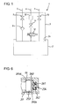
Figure 1 is a circuit diagram of a gas tank used in a first embodiment according to the present invention; -
Figure 2 is a longitudinal sectional view of a manually operated shutoff valve device in the first embodiment according to the present invention; -
Figure 3 is an enlarged fragmentary sectional view showing a part of the manually operated shutoff valve device; -
Figure 4 is an enlarged fragmentary sectional view showing an operated state of the part shown inFigure 3 ; -
Figure 5 is a fragmentary sectional view of a manually operated pressure relief valve device in a second embodiment according to the present invention; and -
Figure 6 is an enlarged fragmentary sectional view of a manually operated shutoff valve device in a third embodiment according to the present invention. - Hereafter, a manually operated shutoff valve device in a first embodiment according to the present invention will be described with reference to
Figures 1 to 4 in the form of being applied to a hydrogen gas tank. Referring now toFigure 1 , agas tank 1 in the first embodiment is provided with a tankmain body 2 for storing hydrogen gas therein and aplug body 3 for closing anopening portion 2a of the tankmain body 2. Theplug body 3 is provided with a plurality of flow passages for making the interior and exterior of the tankmain body 2 communicate with each other and a plurality of valve devices for controlling the flow of hydrogen gas in each of the respective flow passages. - Specifically, the
plug body 3 has formed therein a filling passage 5 for filling the tankmain body 2 with hydrogen gas, asupply passage 6 for supplying the hydrogen gas in the tankmain body 2 outside, and adischarge passage 7 for discharging the hydrogen gas in the tankmain body 2 outside. - The filling passage 5 has arranged thereon a
check valve device 8 for preventing the hydrogen gas stored in the tankmain body 2 from flowing backward and a manually operatedshutoff valve device 9 which can be operated by hand from outside to block the flow of hydrogen gas. Thesupply passage 6 has arranged thereon an electromagneticshutoff valve device 12, a manually operatedshutoff valve device 11 and a pressurereduction valve device 10. Thedischarge passage 7 has a manually operated shutoff valve device 13 arranged thereon. - Hereafter, a first embodiment of the manually operated
shutoff valve device 9 arranged on the filling passage 5 will be described in detail with reference toFigures 2 to 4 . - Referring now to
Figure 2 , aplug body housing 16 constituting theplug body 3 has formed therein a receivinghole 17 with one end opening outside. The receivinghole 17 is connected to afirst flow passage 18 and asecond flow passage 19 which jointly constitute the filling passage 5. Thereceiving hole 17 is composed of a small-diameter hole 17a, an intermediate-diameter hole 17b and a large-diameter hole 17c which are formed in order from the bottom of thereceiving hole 17. Thecheck valve device 8 is arranged to extend from the small-diameter hole 17a to the intermediate-diameter hole 17b, while the manually operatedshutoff valve device 9 is arranged to extend from the intermediate-diameter hole 17b to the large-diameter hole 17c. Thefirst flow passage 18 communicating with the interior of the gas tank 1 (i.e., the tank main body 2) opens into the small-diameter hole 17a, and thesecond flow passage 19 communicating with the outside of thegas tank 1 opens into the intermediate-diameter hole 17b. - The
check valve device 8 is mainly composed of afirst housing 21 fitted in the intermediate-diameter hole 17b of the receivinghole 17, asecond housing 22 bodily jointed with the left end of thefirst housing 21 by being screw-engaged on the left end, and acheck valve body 23 received in thefirst housing 21. Thefirst housing 21 has a small-diameter sleeve portion 21 a fitted in the small-diameter hole 17a, and the clearance in radial directions between the small-diameter sleeve portion 21 a and the small-diameter hole 17a is sealed with sealing means 25 composed of an O-ring and several backup rings. Although terms "left end" and "right end" are used throughout the description only for the purpose of easier understanding with reference to the drawings, they do not limit the present invention and should be interpreted merely as one end and the other end, respectively. - In the
first housing 21, there is received avalve hole 26 receiving thecheck valve body 23, and the right end of thevalve hole 26 is connected to thefirst flow passage 18 through afluid passage 39 formed at a center portion of the small-diameter sleeve portion 21 a. On the left end side of thevalve hole 26, a resin-made seat 27 is arranged to be put between thefirst housing 21 and thesecond housing 22. The resin-made seat 27 is made of, e.g., polyamide resin, and a throughhole 28 is formed at the center portion of the resin-made seat 27. Avalve seat 29 is formed at one end on thevalve hole 26 side of the throughhole 28. Thecheck valve body 23 having a tapered poppet valve which is able to seat on and go away from thevalve seat 29 is slidably inserted in thevalve hole 26 and is urged by means of aspring 30 in the direction toward thevalve seat 29. - High-pressure hydrogen gas is applied through the
first flow passage 18 and thefluid passage 39 to thecheck valve body 23 to move the same in the same direction as urged by thespring 30, so that thecheck valve body 23 ordinarily closes thevalve seat 29. A radial passage and an axial passage are formed in thecheck valve body 23, and in the state that thecheck valve body 23 goes away from thevalve seat 29, the throughhole 28 with thevalve seat 29 formed therearound is brought into communication with thefirst flow passage 18 through the redial passage and the axial passage both formed in thecheck valve body 23 and further through thefluid passage 39 formed in the small-diameter sleeve portion 21 a. - The
second housing 22 takes a generally cylindrical form and is provided with apartition wall 22a at its axial-mid portion. On the right end side of thepartition wall 22a, thesecond housing 22 has formed ascrew hole 22b, into which thefirst housing 21 is screwed at its male screw portion 21 b formed at its left end. The left side of thesecond housing 22 has formed therein a cylindricalconcave portion 33, which receives therein with a ply theright end portion 53d of ashutoff valve body 53 of the manually operatedshutoff valve device 9 configured as described later in detail. A bottom surface of theconcave portion 33, that is, the left end surface of thepartition wall 22a is defined as avalve seat 40 with which a resin-madeseat 62 described later and best shown inFigure 3 is brought into flat surface contact. Ashutoff flow passage 34 is formed at the center portion of thepartition wall 22a to open on thevalve seat 40 and communicates with thevalve seat 29 on thecheck valve body 23 side. Thesecond housing 22 with thevalve seat 40 formed on the bottom surface of theconcave portion 33 constitutes a valve seat member in the claimed invention. - A
filter 35 opening to thesecond flow passage 19 is fitted on the circumferential surface of thesecond housing 22 around theconcave portion 33. Thefilter 35 is in fluid communication with theconcave portion 33 throughradial holes 36 formed in thesecond housing 22. Thus, hydrogen gas can be supplied from thesecond flow passage 19 to the tankmain body 2 through thefilter 35, theradial holes 36, theconcave portion 33, theshutoff flow passage 34, thecheck valve body 23 and the like. - A
hexagonal head portion 37 is formed on the circumferential surface of thefirst housing 21, while a diametrically opposed two-flatted head portion 38 is formed on the circumferential surface of thesecond housing 22. By rotating thehexagonal head portion 37 of thefirst housing 21 with a suitable tool such as wrench in the state that thesecond housing 22 is fixed at the two-flatted head portion 38 against rotation, the male screw portion 21 b of thefirst housing 21 can be screwed into thescrew hole 22b of thesecond housing 22, so that the first andsecond housings check valve device 8 in the assembled state can be assembled and fitted in the receivinghole 17 of theplug body housing 16. - The aforementioned
check valve device 8 is constructed so that thecheck valve body 23 is singly capable of preventing high-pressure hydrogen gas from leaking. To this end, the resin-made seat 27 having thevalve seat 29 which thecheck valve body 23 seats on and goes away from is squeezed between the right end surface of thefirst housing 21 and thepartition wall 22a of thesecond housing 22 when the first and thesecond housings first housing 21 can be increased. - As shown in
Figure 2 , the manually operatedshutoff valve device 9 is composed of afirst plug 51 and asecond plug 52 which are screw-engaged with a screw portion formed on the large-diameter hole 17c of the receivinghole 17, theshutoff valve body 53 slidably fitted in thefirst plug 51, anoperating screw shaft 54 screw-engaged in thesecond plug 52 to be adjustable in position for operating theshutoff valve body 53 to move back and forth, and the like. - The
first plug 51 is provided with afit portion 51 a fitted in the intermediate-diameter hole 17b. The right end of thefit portion 51 a is in contact with the left end portion of the aforementionedsecond housing 22. By screwing thefirst plug 51, thefirst housing 21 jointed with thesecond housing 22 is brought into contact with a bottom surface of the intermediate-diameter hole 17b of the receivinghole 17 to be secured thereon. The clearance between the external surface of thefit portion 51 a of thefirst plug 51 and the intermediate-diameter hole 17b is sealed by sealingmeans 55 composed of an O-ring and several backup rings. Further, thefirst plug 51 slidably fits theshutoff valve body 53 therein on the axis at thefit portion 51 a, and the clearance between the internal surface of thefit portion 51 a and the external surface of theshutoff valve body 53 is sealed by sealingmeans 56 composed of an O-ring and several backup rings. - The
shutoff valve body 53 is made of a metal such as stainless steel. Theright end portion 53d of theshutoff valve body 53 is inserted into theconcave portion 33 of thesecond housing 22 with a play in radial directions. The play defines a clearance around theright end portion 53d of theshutoff valve body 53 relative to the internal surface of theconcave portion 33, and the clearance constitutes a part of a gas pathway from the radial holes 36 to theshutoff flow passage 34. Further, the right end surface of theshutoff valve body 53 has ahollow portion 61 at the center portion thereof, so that anannular protrusion 53a is formed around thehollow portion 61, as best shown inFigure 3 . The ring-shape resin-madeseat 62 is press-fitted in thehollow portion 61 of theshutoff valve body 53 for selectively opening and closing theshutoff flow passage 34 through selective contact with thevalve seat 40 formed on thepartition wall 22a of thesecond housing 22. The resin-madeseat 62 is made of, e.g., polyimide resin and is able to close theshutoff flow passage 34 when brought into flat surface contact with the valve seat 40 (i.e., thepartition wall 22a). The thickness of the resin-madeseat 62 is set to be larger than the depth of thehollow portion 61 in the free or uncompressed state, and thus, the resin-madeseat 62 partly protrudes from the end surface of theannular protrusion 53a in the state that it opens theshutoff flow passage 34. At theright end portion 53d of theshutoff valve body 53, as shown inFigure 3 , there is provided aradial hole 53c which makes a bottom area in thehollow portion 61 communicate with the external surface of theshutoff valve body 53. When the ring-shape resin-madeseat 62 is press-fitted in thehollow portion 61, the air or gas in the bottom area in thehollow portion 61 can be exhausted to the external surface of theshutoff valve body 53 through theradial hole 53c. Therefore, it can be realized to fit the ring-shape resin-madeseat 62 in thehollow portion 61 of theshutoff valve body 53 easily and reliably. - In the manually operated
shutoff valve device 9 wherein theshutoff valve body 53 is brought into a closed position with the pressure being applied thereto, there is a possibility that at the time of valve opening, the resin-madeseat 62 remains in contact with thevalve seat 40 to move relative to theshutoff valve body 53 in such a direction as to come off from theconcave portion 61. In order to prevent this drawback, theshutoff valve body 53 is provided with aradial cutout 53b at one place in the circumferential direction on the right end surface of theannular protrusion 53a, as shown inFigure 3 . Thus, where at the time of valve opening, the resin-madeseat 62 is apt to remain in contact with thevalve seat 40 of thepartition wall 33 and is apt to move relative to theshutoff valve body 53 in the direction to come off from theconcave portion 61, theradial cutout 53b opens the contact surface of the resin-madeseat 62 with thevalve seat 40 to thesecond flow passage 19 side to help the resin-madeseat 62 separate from thevalve seat 40. Further, in this particular embodiment, the relative movement between the ring-shape resin-madeseat 62 and theshutoff valve body 53 can suppressed much more reliably by making the resin-madeseat 62 take a ring shape having agas vent 62a at the center portion thereof and by providing theradial hole 53c. The provision of thegas vent 62a helps the ring-shape resin-madeseat 62 to easily separate from thevalve seat 40 by preventing a negative pressure from being generated therebetween. - The
second plug 52 is screwed into the female screw portion on the large-diameter hole 17c at a position which is outside thefirst plug 51 in the axial direction. The operatingscrew shaft 54 with ahexagonal hole 63 is screw-engaged with thesecond plug 52 to be adjustable in its axial position and can be locked by means of alock nut 64 at a desired position. - A
spring 65 is interposed between thefirst plug 51 and theshutoff valve body 53, and ordinarily, theshutoff valve body 53 is kept by the resilient force of thespring 65 in a retracted position to contact theoperating screw shaft 54 and opens theshutoff flow passage 34. By turning theoperating screw shaft 54 by the use of thehexagonal hole 63 to advance the operatingscrew shaft 54, it becomes possible to move theshutoff valve body 53 against the resilient force of thespring 65. As a consequence, the resin-madeseat 62 provided at theright end portion 53d of theshutoff valve body 53 is brought into flat surface contact with thepartition wall 22a of thesecond housing 22 to be squeezed and closes theshutoff flow passage 34. At this time, the resin-madeseat 62 is compressed a predetermined amount, in which state theannular protrusion 53a of theshutoff valve body 53 is brought into contact with the left end surface of thepartition wall 22a, so that the resin-madeseat 62 is prevented from being squeezed excessively. The operatingscrew shaft 54 is provided thereon with arestriction plate 67 for defining a retracted position of theoperating screw shaft 54. With this construction, the operatingscrew shaft 54 can be prevented from being unscrewed and coming out of thesecond plug 52 in the event that thelock nut 64 is loosened. - In the manually operated
shutoff valve device 9 in the foregoing first embodiment, theshutoff valve body 53 is moved toward thecheck valve body 23 against the resilient force of thespring 65 by turning theoperating screw shaft 54. Thus, the resin-madeseat 62 fitted in theright end portion 53d of theshutoff valve body 53 is brought into flat surface contact with thevalve seat 40 and is pressed on the valve seat 40 (i.e., thepartition wall 22a) of thesecond housing 22 to be compressed, as shown inFigure 4 . As a consequence, theshutoff flow passage 34 opening on thevalve seat 40 is closed, whereby the hydrogen gas in the filling passage 5 is blocked from flowing. - Since the resin-made
seat 62 is compressed a predetermined amount at this time, theannular protrusion 53a of theshutoff valve body 53 is brought into contact with thevalve seat 40, so that the resin-madeseat 62 can be prevented from being squeezed excessively. In addition, since thevalve seat 40 is sealed by bringing the resin-madeseat 62 into flat surface contact with thevalve seat 40, unlike the prior art wherein a taper surface is utilized for sealing, precise machining becomes unnecessary, and freedom is increased in choosing metal materials used for the valve seat. It should be noted that theright end portion 53d of theshutoff valve body 53 is formed as a large-diameter portion. This large-diameter portion 53d serves as a restriction portion engageable with the right end surface of thefirst plug 51, so that theshutoff valve body 53 can be prevented from coming out of thefirst plug 51 in the event that either theoperating screw shaft 54 is unscrewed from thesecond plug 52 or thesecond plug 52 is unscrewed from theplug body housing 16. - The
shutoff valve body 53 can be moved by the resilient force of thespring 65 in the direction to go away from thecheck valve body 23 by turning theoperating screw shaft 54 in a direction opposite to that as aforementioned. The resin-madeseat 62 fitted in theright end portion 53d of theshutoff valve body 53 goes away from thevalve seat 40 of thesecond housing 22, whereby theshutoff flow passage 34 is opened. - In this state, hydrogen gas is admitted from the
second flow passage 19 and is flown through thefilter 35 into theconcave portion 33. The hydrogen gas acts on thecheck valve body 23 through theshutoff flow passage 34 and pushes thecheck valve body 23 against the resilient force of thespring 30. As a result, thevalve seat 29 is opened, whereby the hydrogen gas is flown into thefirst flow passage 18 to be filled in the tankmain body 2. - Next, a second embodiment according to the present invention will be described with reference to
Figure 5 . The difference of the second embodiment from the foregoing first embodiment resides in that the present invention is applied to a pressurerelief valve device 70 which performs a pressure relief operation by opening ashutoff flow passage 134 opening on avalve seat 140. Therefore, the difference from the first embodiment will be mainly described hereafter, and the description of the same structural components will be omitted since they are given the same reference numerals. - In the second embodiment, a receiving
hole 117 is formed in theplug body housing 16, and theshutoff flow passage 134 which is selectively opened and closed by avalve body 153 opens on avalve seat 140 formed on a bottom surface of the receivinghole 117. Thevalve body 153 is slidably fitted in thefirst plug 51 fixedly screwed in the receivinghole 117, and ahollow portion 161 is formed at the right end surface of thevalve body 153 in the same manner as the foregoing first embodiment. A press-fit hole 71 which is smaller in diameter than thehollow portion 161 is formed at a bottom surface of thehollow portion 161. A resin-madeseat 162 taking a T-shape when taken along the axis is received in thehollow portion 161 with a play provided in radial directions between a large-diameter portion of the resin-madeseat 162 and the internal surface of thehollow portion 161 and is press-fitted in the press-fit hole 71 at a small-diameter portion thereof. - The resin-made
seat 162 is made of, e.g., polyimide resin and is brought into flat surface contact with thevalve seat 140 to close theshutoff flow passage 134. The thickness at the large-diameter portion of the resin-madeseat 162 is set to be larger than the depth of thehollow portion 161 in the free or uncompressed state, and the resin-madeseat 162 partly protrudes from the right end surface of anannular protrusion 153a in the state that it opens theshutoff flow passage 134. By manually turning theoperating screw shaft 54 which is screwed in thesecond plug 52 to be adjustable in its axial position, thevalve body 153 is moved as it compresses the resin-madeseat 162 until theannular protrusion 153a comes into contact with the valve seat 140 (i.e., the bottom surface of the receiving hole 117). - The pressure
relief valve device 70 in the second embodiment is not one that performs a valve opening operation with a substantial pressure acting on thevalve body 153. However, for a different purpose, acutout 153b is formed at one place in the circumferential direction on the right end surface of theannular protrusion 153a of thevalve body 153. - That is, there may arise a situation for example that foreign matter is put between the resin-made
seat 162 and thevalve seat 140, whereby theshutoff flow passage 134 is not closed completely by the resin-madeseat 162. Even in this situation, however, the abutting contact of theannular protrusion 153a with thevalve seat 140 may make such a state as if theshutoff flow passage 134 were completely closed by the resin-madeseat 162. In order to overcome this deficiency, thecutout 153b is formed at one place in the circumferential direction on the end surface of theannular protrusion 153a, and thecutout 153 works to prevent theshutoff flow passage 134 from being closed completely even in the event that theannular protrusion 153a is brought into contact with thevalve seat 140 with foreign matter being put between the resin-madeseat 162 and thevalve seat 140 and that the resin-madeseat 162 does not completely close theshutoff flow passage 134. In this way, the aforementioned deficiency can be detected at an inspection process before product shipment, so that the reliability of the products can be enhanced. - In the foregoing second embodiment, the
valve body 153 is moved against the resilient force of thespring 65 by turning theoperating screw shaft 54. Thus, the resin-madeseat 162 fitted in theright end portion 153d of thevalve body 153 is brought into flat surface contact with thevalve seat 140 and is pressed on thevalve seat 140 to be compressed. As a consequence, theshutoff flow passage 134 opening on thevalve seat 140 is closed, whereby the communication between theshutoff flow passage 134 and apressure relief hole 73 is blocked. Here, it should be noted that when compressed in the moving direction of thevalve body 153, the resin-madeseat 162 runs in radial directions to occupy the clearance made relative to the internal surface of thehollow portion 161. - Since the resin-made
seat 162 is compressed a predetermined amount at this time, theannular protrusion 153a of theshutoff valve body 153 is brought into contact with thevalve seat 140, and thus, the resin-madeseat 162 can be prevented from being squeezed excessively. In addition, since thevalve seat 140 is sealed by bringing the resin-madeseat 162 into flat surface contact with thevalve seat 140, unlike the prior art wherein a taper surface is utilized for sealing, precise machining becomes unnecessary, and freedom is increased in choosing metal materials used for thevalve seat 140. Accordingly, theplug body housing 16 with thevalve seat 140 formed thereon can be made of aluminum for light weight. In addition, even where thevalve body 153 and theplug body housing 16 are constituted with different metal materials of stainless steel and aluminum, burs as occurring in the prior art are not formed by the deformation of the seal portion, and thus, it does not occur that the valve device is harmed in function. - Further, by forming the
cutout 153b on the end surface of theannular protrusion 153a of thevalve body 153, foreign matter put between the resin-madeseat 162 and thevalve seat 140 can be detected easily at an inspection process with theannular protrusion 153a being in contact with thevalve seat 140, so that it can be realized to enhance the reliability of the products. -
Figure 6 shows a part of a third embodiment according to the present invention. The difference from the foregoing second embodiment resides in that a resin-madeseat 262 is fitted in avalve seat 240 with which theright end portion 253d of avalve body 253 is brought into contact. - In the third embodiment, a
hollow portion 261 is formed on thevalve seat 240 with which the right end surface of thevalve body 253 is brought into contact, and ashutoff flow passage 234 opens to thehollow portion 261. A ring-shape resin-madeseat 262 is press-fitted in thehollow portion 261, and the thickness of the resin-madeseat 262 is set to be larger than the depth of thehollow portion 261 in the free or uncompressed state. Thevalve body 253 for flat surface contact with the resin-madeseat 262 is moved as it compresses the resin-madeseat 262 until it comes into contact with thevalve seat 240, and closes theshutoff flow passage 234 to block the flow of gas. The same effects as those in the foregoing embodiments can be achieved also in the third embodiment. - In the foregoing embodiments, description has been made taking examples wherein the valve device for selectively opening and closing the shutoff flow passage 34 (134, 234) is applied to the manually operated
shutoff valve device 9 and the pressurerelief valve device 70. However, the present invention is not limited to such valve devices and is applicable to various valve devices of the construction that the shutoff flow passage 34 (134, 234) opening on the valve seat 40 (140, 240) is selectively closed and opened by the valve body 53 (153, 253) through the resin-made seat 62 (162, 262). - Further, although in the foregoing embodiments, description has been made taking examples that the valve body 53 (153, 253) is made of stainless steel while the
plug body housing 16 with which the valve body is brought into contact is made of aluminum for light weight, both of the valve body and the plug body housing can be made of stainless steel because the accuracy in alignment is no longer required. Even in this case, there can be attained advantages that portions which should be machined precisely can be decreased in number and that the freedom can be enhanced in choosing the metal materials used for the valve seat. - Various features and many of the attendant advantages in the foregoing embodiments will be summarized as follows:
- In the valve device in any of the foregoing first to third embodiments typically shown in
Figures 2, 3 ,5 and6 , the valve device takes the construction that thehollow portion valve body valve seat seat mechanism - In the valve device in the foregoing first embodiment typically shown in
Figure 2 and 3 , thevalve seat member 22 having the generally cylindricalconcave portion 33 which forms thevalve seat 40 at a bottom surface thereof is made of a metal, and thevalve body 53 is made of a metal which is the same or different in kind from that of the valve seat member and receives the resin-madeseat 62 in thehollow portion 61 formed in the end portion of thevalve body 53. Thus, when the valve device is closed, the resin-made seat is pressed on the valve seat and is compressed to bring the end surface of the valve body into contact with the valve seat. Accordingly, precise coaxial alignment is no longer required between the valve body and the valve seat, and the resin-made seat can be prevented from being squeezed excessively. - In the valve device in the foregoing first embodiment typically shown in
Figure 2 and 3 , the resin-madeseat 62 takes a ring shape having thegas vent 62a at the center part thereof. Thus, when thevalve body 53 leaves thevalve seat 40 to open theshutoff flow passage 34, the generation of a negative pressure between the resin-made seat and the valve seat is prevented, so that the ring-shape resin-made seat can easily be separated from the valve seat to move together with valve body. - In the valve device in the foregoing first and second embodiments typically shown in
Figure 3 and5 , since thevalve body radial hole hollow portion seat - The valve device in any of the foregoing first to third embodiments typically shown in
Figures 2, 3 ,5 and6 is used as the manually operatedshutoff valve device 9. In the manually operatedshutoff valve device 9, since freedom can be enhanced in choosing metal materials used for thevalve seat valve body housing 16 of the manually operatedshutoff valve device 9, so that the same can be lightened. - The manually operated
shutoff valve device 9 in any of the foregoing first to third embodiments typically shown inFigure 2 is provided with thevalve body housing 16; thefirst plug 51 fixedly screwed into the receivinghole 17 of thevalve body housing 16; thevalve body flow passage spring member 65 for urging the valve body in the direction to open the flow passage; thesecond plug 52 fixedly screwed into the receiving hole of the valve body housing; and theoperating screw shaft 54 screwed into the second plug to be adjustable in the axial position thereof for moving the valve body against the resilient force of the spring member. With this configuration, by manually operating the operating screw shaft, the valve body can be brought into contact with the valve seat with the resin-made seat being compressed. This structure realizes the manually operated shutoff valve device which makes precise coaxial alignment unnecessary between the valve body and the valve seat and which can prevent the resin-made seat from being squeezed excessively. - In any of the foregoing first to third embodiments, the manually operated
shutoff valve device 9 typically shown inFigure 2 , since the operatingscrew shaft 54 is provided thereon with therestriction plate 67 serving as a restriction member, so that the operating screw shaft can be prevented from being unscrewed from thesecond plug 52. - Obviously, numerous further modifications and variations of the present invention are possible in light of the above teachings. It is therefore to be understood that within the scope of the appended claims, the present invention may be practiced otherwise than as specifically described herein.
- In a valve device for selectively opening and closing a flow passage formed to open on a valve seat by a valve body through a resin-made seat, a hollow portion is formed on either one of the valve body and the valve seat and receives the resin-made seat therein, the resin-made seat has a thickness so that the resin-made seat partly protrudes from the hollow portion, and when the valve body is operated to close the flow passage, the resin-made seat is compressed to bring an end surface of the valve body into contact with the valve seat.
Claims (8)
- A valve device for selectively opening and closing a flow passage, the valve device comprising:a valve seat with the flow passage opening thereon;a valve body movable for selectively opening and closing the flow passage at an end portion thereof;a hollow portion formed on either one of the valve body and the valve seat;a resin-made seat received in the hollow portion and configured to be brought into flat surface contact with the other of the valve body and the valve seat, the resin-made seat having a thickness so that the resin-made seat partly protrudes from the hollow portion; anda mechanism for operating the valve body to bring the end portion of the valve body into contact with the valve seat with the resin-made seat being compressed.
- The valve device as set forth in Claim 1, further comprising a valve seat member made of a metal and having a generally cylindrical concave portion which forms the valve seat at a bottom surface thereof, and wherein:the valve body is made of a metal which is the same or different in kind from that of the valve seat member and receives the resin-made seat in the hollow portion formed at the end portion of the valve body;the resin-made seat has the thickness so that the resin-made seat partly protrudes from the end portion of the valve body, and is configured to be brought into flat surface contact with the valve seat of the valve seat member; andthe mechanism is configured to bring the end portion of the valve body into contact with the valve seat of the valve seat member with the resin-made seat being compressed and to close the flow passage opening on the valve seat of the valve seat member when operated to press the resin-made seat on the valve seat.
- The valve device as set forth in Claim 2, wherein the resin-made seat takes a ring shape having a gas vent at the center part thereof.
- The valve device as set forth in Claim 3, wherein the valve body is provided at the end portion thereof with a radial hole which makes a bottom area in the hollow portion communicate with the external surface of the valve body.
- A manually operated shutoff valve device using the valve device as set forth in Claim 1, wherein the mechanism for operating the valve body is configured to be operated manually.
- The manually operated shutoff valve device as set forth in Claim 5, further comprising:a valve body housing;a first plug fixedly screwed into a receiving hole of the valve body housing and receiving therein the valve body to be axially slidable for selectively opening and closing the flow passage;an urging member for urging the valve body in a direction to open the flow passage;a second plug fixedly screwed into the receiving hole of the valve body housing; andan operating screw shaft screwed into the second plug to be manually adjustable in the axial position thereof for moving the valve body against the resilient force of the urging member, wherein the mechanism for operating the valve body is composed of the second plug and the operating screw shaft.
- The manually operated shutoff valve device as set forth in Claim 6, wherein the operating screw shaft is provided thereon with a restriction member for preventing the operating screw shaft from being unscrewed from the second plug.
- The manually operated shutoff valve device as set forth in Claim 6, further comprising:a lock nut engaged with the operating screw shaft and the second plug for locking the operating screw shaft on the second plug, andwherein the operating screw shaft is provided thereon with a restriction member for preventing the operating screw shaft from being unscrewed from the second plug so that the operating screw shaft is prevented from coming out of the second plug in the event that the lock nut is loosened.
Applications Claiming Priority (1)
| Application Number | Priority Date | Filing Date | Title |
|---|---|---|---|
| JP2007247615A JP2009079623A (en) | 2007-09-25 | 2007-09-25 | Valve device and manual open / close valve device |
Publications (3)
| Publication Number | Publication Date |
|---|---|
| EP2042790A2 true EP2042790A2 (en) | 2009-04-01 |
| EP2042790A3 EP2042790A3 (en) | 2009-12-30 |
| EP2042790B1 EP2042790B1 (en) | 2011-12-28 |
Family
ID=40091405
Family Applications (1)
| Application Number | Title | Priority Date | Filing Date |
|---|---|---|---|
| EP08164968A Ceased EP2042790B1 (en) | 2007-09-25 | 2008-09-24 | Valve device and manually operated shutoff valve device |
Country Status (3)
| Country | Link |
|---|---|
| US (1) | US8474792B2 (en) |
| EP (1) | EP2042790B1 (en) |
| JP (1) | JP2009079623A (en) |
Cited By (1)
| Publication number | Priority date | Publication date | Assignee | Title |
|---|---|---|---|---|
| KR20160099696A (en) * | 2014-02-20 | 2016-08-22 | 가부시키가이샤 후지킨 | Valve body and high temperature valve |
Families Citing this family (25)
| Publication number | Priority date | Publication date | Assignee | Title |
|---|---|---|---|---|
| JP5412864B2 (en) * | 2009-02-17 | 2014-02-12 | 株式会社ジェイテクト | Shut-off valve for high-pressure hydrogen gas |
| JP5272785B2 (en) | 2009-02-17 | 2013-08-28 | 株式会社ジェイテクト | Valve device |
| EP2592313B1 (en) * | 2011-11-14 | 2016-07-13 | Idex Health&Science LLC | Rotary shear valve assembly with a polymer insert device |
| JP5872283B2 (en) * | 2011-12-27 | 2016-03-01 | Kyb株式会社 | Pressure relief valve |
| US9404593B2 (en) | 2013-05-21 | 2016-08-02 | Hamilton Sundstrand Corporation | Vent valve |
| US9982511B2 (en) | 2014-01-03 | 2018-05-29 | Proserv Operations, Inc. | Dirty fluid pressure regulator and control valve |
| JP6373713B2 (en) * | 2014-10-08 | 2018-08-15 | 株式会社ジェイテクト | Valve device |
| US10670155B2 (en) | 2015-10-05 | 2020-06-02 | Proserv Gilmore Valve Llc | Latching poppet valve |
| US10487951B2 (en) | 2016-01-22 | 2019-11-26 | Proserv Operations, Inc. | Non-interflow directional control valve |
| US10591076B2 (en) * | 2016-09-15 | 2020-03-17 | Proserv Operations, Inc. | Low friction hydraulic circuit control components |
| US10739796B2 (en) | 2017-09-22 | 2020-08-11 | Proserv Gilmore Valve Llc | Pressure regulator with reconfigurable hydraulic dampening |
| US10633951B2 (en) | 2017-09-22 | 2020-04-28 | Proserv Operations, Inc. | Pressure regulator with user selectable dampening |
| DE102018100519A1 (en) * | 2018-01-11 | 2019-07-11 | Voith Patent Gmbh | Valve drive with high-speed function |
| US11022226B2 (en) | 2018-03-20 | 2021-06-01 | Proserv Operations, Inc. | Microfluidic valve |
| US11054050B2 (en) | 2018-08-13 | 2021-07-06 | Proserv Operations Inc. | Valve with press-fit insert |
| US11209096B2 (en) | 2018-11-19 | 2021-12-28 | Proserv Operations, Inc. | Bilateral and throttling directional control valve |
| US11261982B2 (en) | 2019-06-27 | 2022-03-01 | Proserv Gilmore Valve Llc | Pressure relief valve with bi-directional seat |
| US11828370B2 (en) | 2020-01-02 | 2023-11-28 | Proserv Gilmore Valve Llc | Check valve with conforming seat |
| US11781397B2 (en) * | 2020-09-02 | 2023-10-10 | George Todd Lowry | Integral check valve lock open device for oil and gas equipment |
| JP7554679B2 (en) * | 2021-01-25 | 2024-09-20 | 日立Astemo株式会社 | Steering gear, ship |
| EP4441405A1 (en) | 2021-12-03 | 2024-10-09 | Proserv Gilmore Valve LLC | Pressure relief valve for high-pressure fluids, including abrasives laden fluids |
| WO2023176734A1 (en) * | 2022-03-15 | 2023-09-21 | 川崎重工業株式会社 | Hydrogen gas valve device and hydrogen gas valve body equipped therewith |
| JP2024172235A (en) * | 2023-05-31 | 2024-12-12 | Ckd株式会社 | Fluid Control Valve |
| WO2025220116A1 (en) * | 2024-04-16 | 2025-10-23 | 株式会社ジェイテクト | Fluid tank |
| CN121139513B (en) * | 2025-11-18 | 2026-05-08 | 山东大学 | A self-sealing accumulator charging valve for high-voltage environments and its usage method |
Citations (2)
| Publication number | Priority date | Publication date | Assignee | Title |
|---|---|---|---|---|
| JP2006144841A (en) | 2004-11-17 | 2006-06-08 | Toyoda Mach Works Ltd | Fixing structure and manual valve of valve device |
| JP2007247615A (en) | 2006-03-18 | 2007-09-27 | Toyota Motor Corp | Intake control device for internal combustion engine |
Family Cites Families (19)
| Publication number | Priority date | Publication date | Assignee | Title |
|---|---|---|---|---|
| GB686404A (en) | 1950-03-29 | 1953-01-21 | Henry Ronald Godfrey | Improvements in and relating to washer or jumper assemblies for taps and the like |
| US2895497A (en) * | 1956-04-18 | 1959-07-21 | Henry Valve Company Inc | Packless valve |
| CH360258A (en) | 1956-11-12 | 1962-02-15 | Carl Von Platen Baltzar | Valve |
| US2963267A (en) | 1959-04-21 | 1960-12-06 | Allide Control Company Inc | Valve |
| US3081062A (en) * | 1960-10-03 | 1963-03-12 | Pacific Valves Inc | Balance pressurized seal globe valve |
| AU4008368A (en) | 1968-07-03 | 1970-01-08 | F. H. Evans & Company Limited | Taps |
| US4172585A (en) * | 1978-03-23 | 1979-10-30 | Automatic Switch Company | Valve disk and holder assembly and valve incorporating it |
| US4682759A (en) * | 1983-10-20 | 1987-07-28 | Outboard Marine Corporation | Relief valve for hydraulic systems |
| SE456597B (en) | 1987-02-12 | 1988-10-17 | Scandot System Ab | DEVICE FOR A VALVE ARRANGEMENT FOR THE EXHAUST OF LIQUID BY A SCRIPLINE PRINTER |
| US5452738A (en) * | 1994-02-22 | 1995-09-26 | Amcast Industrial Corporation | Crashworthy solenoid actuated valve for CNG powered vehicle |
| US5474104A (en) * | 1995-01-17 | 1995-12-12 | Superior Valve Company | Refueling check valve for compressed natural gas powered vehicles |
| JP3129658B2 (en) * | 1996-04-26 | 2001-01-31 | 本田技研工業株式会社 | Pressurized fuel pipe structure for automobile and pipe leak inspection method |
| GB9724168D0 (en) * | 1997-11-14 | 1998-01-14 | Air Prod & Chem | Gas control device and method of supplying gas |
| JP2000065240A (en) * | 1998-08-21 | 2000-03-03 | Neriki:Kk | Stop valve |
| CA2276794A1 (en) * | 1999-06-23 | 2000-12-23 | Johnny Yang | Diverter tub spout body |
| US7128080B2 (en) | 1999-08-09 | 2006-10-31 | Allied Healthcare Products, Inc. | Surge prevention device |
| US6957661B1 (en) * | 2003-03-19 | 2005-10-25 | Harsco Technologies Corporation | Valve with pressurization rate reduction device |
| US7387135B2 (en) * | 2004-12-23 | 2008-06-17 | Mks Instruments, Inc. | Valve assembly having rigid seating surfaces |
| JP5217625B2 (en) * | 2008-05-22 | 2013-06-19 | 株式会社ジェイテクト | Valve device |
-
2007
- 2007-09-25 JP JP2007247615A patent/JP2009079623A/en active Pending
-
2008
- 2008-09-22 US US12/235,077 patent/US8474792B2/en not_active Expired - Fee Related
- 2008-09-24 EP EP08164968A patent/EP2042790B1/en not_active Ceased
Patent Citations (3)
| Publication number | Priority date | Publication date | Assignee | Title |
|---|---|---|---|---|
| JP2006144841A (en) | 2004-11-17 | 2006-06-08 | Toyoda Mach Works Ltd | Fixing structure and manual valve of valve device |
| EP1813856A1 (en) | 2004-11-17 | 2007-08-01 | JTEKT Corporation | Assembled structure of valve device, plug body, and manual valve |
| JP2007247615A (en) | 2006-03-18 | 2007-09-27 | Toyota Motor Corp | Intake control device for internal combustion engine |
Cited By (2)
| Publication number | Priority date | Publication date | Assignee | Title |
|---|---|---|---|---|
| KR20160099696A (en) * | 2014-02-20 | 2016-08-22 | 가부시키가이샤 후지킨 | Valve body and high temperature valve |
| US10731763B2 (en) | 2014-02-20 | 2020-08-04 | Fujikin Incorporated | Valve element and high-temperature-oriented valve |
Also Published As
| Publication number | Publication date |
|---|---|
| US8474792B2 (en) | 2013-07-02 |
| EP2042790B1 (en) | 2011-12-28 |
| EP2042790A3 (en) | 2009-12-30 |
| US20090108225A1 (en) | 2009-04-30 |
| JP2009079623A (en) | 2009-04-16 |
Similar Documents
| Publication | Publication Date | Title |
|---|---|---|
| EP2042790B1 (en) | Valve device and manually operated shutoff valve device | |
| CN102197250B (en) | Valve system of high pressure tank for vehicle | |
| US10955091B2 (en) | Tank valve | |
| US10655787B2 (en) | Valve mechanism for high pressure tank and valve device for high pressure tank | |
| US7669612B2 (en) | Pipe coupling and male coupling member | |
| CA2908456C (en) | Valve device | |
| EP0077828A4 (en) | Pressure-responsive shut-off valve. | |
| EP3557115B1 (en) | Valve device | |
| US8371330B2 (en) | Valve device | |
| EP1813856A1 (en) | Assembled structure of valve device, plug body, and manual valve | |
| JP7123246B2 (en) | tank device for storing gaseous media | |
| JPH1194197A (en) | Valve device for gas cylinder and pressure reducing valve thereof | |
| CN106090349B (en) | Valve gear and lifting head | |
| US20040231727A1 (en) | Pressure reducing valve | |
| US9400506B2 (en) | Pressure reducer | |
| EP1378692B1 (en) | Valve | |
| US8931754B2 (en) | Safety valve and electromagnetic valve | |
| JP2023547420A (en) | Tank device for storing gaseous media | |
| US20100207047A1 (en) | Gas shutoff valve | |
| US7134638B2 (en) | Stop valve for gas tank | |
| JP2008052474A (en) | Pressure reducing valve | |
| LU507722B1 (en) | Device for gas cylinder with gas refill port connected between shut-off valve and regulator | |
| US20250369529A1 (en) | Pressure reduction valve and production method for pressure reduction valve | |
| US20040050426A1 (en) | Damper valve and hydraulic power steering apparatus using the same | |
| CN118891466A (en) | Overcurrent prevention valve and tank valve device provided with same |
Legal Events
| Date | Code | Title | Description |
|---|---|---|---|
| PUAI | Public reference made under article 153(3) epc to a published international application that has entered the european phase |
Free format text: ORIGINAL CODE: 0009012 |
|
| AK | Designated contracting states |
Kind code of ref document: A2 Designated state(s): AT BE BG CH CY CZ DE DK EE ES FI FR GB GR HR HU IE IS IT LI LT LU LV MC MT NL NO PL PT RO SE SI SK TR |
|
| AX | Request for extension of the european patent |
Extension state: AL BA MK RS |
|
| PUAL | Search report despatched |
Free format text: ORIGINAL CODE: 0009013 |
|
| AK | Designated contracting states |
Kind code of ref document: A3 Designated state(s): AT BE BG CH CY CZ DE DK EE ES FI FR GB GR HR HU IE IS IT LI LT LU LV MC MT NL NO PL PT RO SE SI SK TR |
|
| AX | Request for extension of the european patent |
Extension state: AL BA MK RS |
|
| 17P | Request for examination filed |
Effective date: 20100517 |
|
| AKX | Designation fees paid |
Designated state(s): DE FR |
|
| GRAP | Despatch of communication of intention to grant a patent |
Free format text: ORIGINAL CODE: EPIDOSNIGR1 |
|
| GRAS | Grant fee paid |
Free format text: ORIGINAL CODE: EPIDOSNIGR3 |
|
| GRAA | (expected) grant |
Free format text: ORIGINAL CODE: 0009210 |
|
| AK | Designated contracting states |
Kind code of ref document: B1 Designated state(s): DE FR |
|
| REG | Reference to a national code |
Ref country code: DE Ref legal event code: R096 Ref document number: 602008012302 Country of ref document: DE Effective date: 20120308 |
|
| PLBE | No opposition filed within time limit |
Free format text: ORIGINAL CODE: 0009261 |
|
| STAA | Information on the status of an ep patent application or granted ep patent |
Free format text: STATUS: NO OPPOSITION FILED WITHIN TIME LIMIT |
|
| 26N | No opposition filed |
Effective date: 20121001 |
|
| REG | Reference to a national code |
Ref country code: DE Ref legal event code: R097 Ref document number: 602008012302 Country of ref document: DE Effective date: 20121001 |
|
| REG | Reference to a national code |
Ref country code: FR Ref legal event code: PLFP Year of fee payment: 9 |
|
| REG | Reference to a national code |
Ref country code: FR Ref legal event code: PLFP Year of fee payment: 10 |
|
| REG | Reference to a national code |
Ref country code: FR Ref legal event code: PLFP Year of fee payment: 11 |
|
| PGFP | Annual fee paid to national office [announced via postgrant information from national office to epo] |
Ref country code: FR Payment date: 20230808 Year of fee payment: 16 Ref country code: DE Payment date: 20230802 Year of fee payment: 16 |
|
| REG | Reference to a national code |
Ref country code: DE Ref legal event code: R119 Ref document number: 602008012302 Country of ref document: DE |
|
| PG25 | Lapsed in a contracting state [announced via postgrant information from national office to epo] |
Ref country code: DE Free format text: LAPSE BECAUSE OF NON-PAYMENT OF DUE FEES Effective date: 20250401 |
|
| PG25 | Lapsed in a contracting state [announced via postgrant information from national office to epo] |
Ref country code: FR Free format text: LAPSE BECAUSE OF NON-PAYMENT OF DUE FEES Effective date: 20240930 |