EP2042764A1 - Constant velocity universal joint - Google Patents
Constant velocity universal joint Download PDFInfo
- Publication number
- EP2042764A1 EP2042764A1 EP07742674A EP07742674A EP2042764A1 EP 2042764 A1 EP2042764 A1 EP 2042764A1 EP 07742674 A EP07742674 A EP 07742674A EP 07742674 A EP07742674 A EP 07742674A EP 2042764 A1 EP2042764 A1 EP 2042764A1
- Authority
- EP
- European Patent Office
- Prior art keywords
- constant velocity
- component
- velocity universal
- universal joint
- circumferential surface
- Prior art date
- Legal status (The legal status is an assumption and is not a legal conclusion. Google has not performed a legal analysis and makes no representation as to the accuracy of the status listed.)
- Withdrawn
Links
- 239000011241 protective layer Substances 0.000 claims description 11
- 239000004519 grease Substances 0.000 claims description 7
- 239000000470 constituent Substances 0.000 claims description 2
- 230000000052 comparative effect Effects 0.000 description 12
- MBMLMWLHJBBADN-UHFFFAOYSA-N Ferrous sulfide Chemical compound [Fe]=S MBMLMWLHJBBADN-UHFFFAOYSA-N 0.000 description 4
- 238000005452 bending Methods 0.000 description 4
- 238000006243 chemical reaction Methods 0.000 description 4
- 230000020169 heat generation Effects 0.000 description 4
- CWQXQMHSOZUFJS-UHFFFAOYSA-N molybdenum disulfide Chemical compound S=[Mo]=S CWQXQMHSOZUFJS-UHFFFAOYSA-N 0.000 description 4
- 229910052982 molybdenum disulfide Inorganic materials 0.000 description 4
- 239000000126 substance Substances 0.000 description 4
- 230000002745 absorbent Effects 0.000 description 3
- 239000002250 absorbent Substances 0.000 description 3
- 238000010586 diagram Methods 0.000 description 3
- 230000000694 effects Effects 0.000 description 3
- 229910000831 Steel Inorganic materials 0.000 description 2
- 230000005540 biological transmission Effects 0.000 description 2
- 238000010273 cold forging Methods 0.000 description 2
- 230000007423 decrease Effects 0.000 description 2
- 238000005242 forging Methods 0.000 description 2
- 238000010791 quenching Methods 0.000 description 2
- 230000000171 quenching effect Effects 0.000 description 2
- 230000009467 reduction Effects 0.000 description 2
- 239000010959 steel Substances 0.000 description 2
- 239000002562 thickening agent Substances 0.000 description 2
- 229910002923 B–O–B Inorganic materials 0.000 description 1
- 238000005299 abrasion Methods 0.000 description 1
- 230000008901 benefit Effects 0.000 description 1
- 239000002131 composite material Substances 0.000 description 1
- 230000006866 deterioration Effects 0.000 description 1
- 230000006872 improvement Effects 0.000 description 1
- 239000000463 material Substances 0.000 description 1
- 238000005259 measurement Methods 0.000 description 1
- 238000000034 method Methods 0.000 description 1
- 230000008569 process Effects 0.000 description 1
Images


Classifications
-
- F—MECHANICAL ENGINEERING; LIGHTING; HEATING; WEAPONS; BLASTING
- F16—ENGINEERING ELEMENTS AND UNITS; GENERAL MEASURES FOR PRODUCING AND MAINTAINING EFFECTIVE FUNCTIONING OF MACHINES OR INSTALLATIONS; THERMAL INSULATION IN GENERAL
- F16D—COUPLINGS FOR TRANSMITTING ROTATION; CLUTCHES; BRAKES
- F16D3/00—Yielding couplings, i.e. with means permitting movement between the connected parts during the drive
- F16D3/16—Universal joints in which flexibility is produced by means of pivots or sliding or rolling connecting parts
- F16D3/20—Universal joints in which flexibility is produced by means of pivots or sliding or rolling connecting parts one coupling part entering a sleeve of the other coupling part and connected thereto by sliding or rolling members
- F16D3/22—Universal joints in which flexibility is produced by means of pivots or sliding or rolling connecting parts one coupling part entering a sleeve of the other coupling part and connected thereto by sliding or rolling members the rolling members being balls, rollers, or the like, guided in grooves or sockets in both coupling parts
- F16D3/223—Universal joints in which flexibility is produced by means of pivots or sliding or rolling connecting parts one coupling part entering a sleeve of the other coupling part and connected thereto by sliding or rolling members the rolling members being balls, rollers, or the like, guided in grooves or sockets in both coupling parts the rolling members being guided in grooves in both coupling parts
- F16D3/224—Universal joints in which flexibility is produced by means of pivots or sliding or rolling connecting parts one coupling part entering a sleeve of the other coupling part and connected thereto by sliding or rolling members the rolling members being balls, rollers, or the like, guided in grooves or sockets in both coupling parts the rolling members being guided in grooves in both coupling parts the groove centre-lines in each coupling part lying on a sphere
- F16D3/2245—Universal joints in which flexibility is produced by means of pivots or sliding or rolling connecting parts one coupling part entering a sleeve of the other coupling part and connected thereto by sliding or rolling members the rolling members being balls, rollers, or the like, guided in grooves or sockets in both coupling parts the rolling members being guided in grooves in both coupling parts the groove centre-lines in each coupling part lying on a sphere where the groove centres are offset from the joint centre
-
- F—MECHANICAL ENGINEERING; LIGHTING; HEATING; WEAPONS; BLASTING
- F16—ENGINEERING ELEMENTS AND UNITS; GENERAL MEASURES FOR PRODUCING AND MAINTAINING EFFECTIVE FUNCTIONING OF MACHINES OR INSTALLATIONS; THERMAL INSULATION IN GENERAL
- F16D—COUPLINGS FOR TRANSMITTING ROTATION; CLUTCHES; BRAKES
- F16D3/00—Yielding couplings, i.e. with means permitting movement between the connected parts during the drive
- F16D3/16—Universal joints in which flexibility is produced by means of pivots or sliding or rolling connecting parts
- F16D3/20—Universal joints in which flexibility is produced by means of pivots or sliding or rolling connecting parts one coupling part entering a sleeve of the other coupling part and connected thereto by sliding or rolling members
- F16D3/22—Universal joints in which flexibility is produced by means of pivots or sliding or rolling connecting parts one coupling part entering a sleeve of the other coupling part and connected thereto by sliding or rolling members the rolling members being balls, rollers, or the like, guided in grooves or sockets in both coupling parts
- F16D3/223—Universal joints in which flexibility is produced by means of pivots or sliding or rolling connecting parts one coupling part entering a sleeve of the other coupling part and connected thereto by sliding or rolling members the rolling members being balls, rollers, or the like, guided in grooves or sockets in both coupling parts the rolling members being guided in grooves in both coupling parts
-
- F—MECHANICAL ENGINEERING; LIGHTING; HEATING; WEAPONS; BLASTING
- F16—ENGINEERING ELEMENTS AND UNITS; GENERAL MEASURES FOR PRODUCING AND MAINTAINING EFFECTIVE FUNCTIONING OF MACHINES OR INSTALLATIONS; THERMAL INSULATION IN GENERAL
- F16D—COUPLINGS FOR TRANSMITTING ROTATION; CLUTCHES; BRAKES
- F16D3/00—Yielding couplings, i.e. with means permitting movement between the connected parts during the drive
- F16D3/16—Universal joints in which flexibility is produced by means of pivots or sliding or rolling connecting parts
- F16D3/20—Universal joints in which flexibility is produced by means of pivots or sliding or rolling connecting parts one coupling part entering a sleeve of the other coupling part and connected thereto by sliding or rolling members
- F16D3/22—Universal joints in which flexibility is produced by means of pivots or sliding or rolling connecting parts one coupling part entering a sleeve of the other coupling part and connected thereto by sliding or rolling members the rolling members being balls, rollers, or the like, guided in grooves or sockets in both coupling parts
- F16D3/223—Universal joints in which flexibility is produced by means of pivots or sliding or rolling connecting parts one coupling part entering a sleeve of the other coupling part and connected thereto by sliding or rolling members the rolling members being balls, rollers, or the like, guided in grooves or sockets in both coupling parts the rolling members being guided in grooves in both coupling parts
- F16D3/2237—Universal joints in which flexibility is produced by means of pivots or sliding or rolling connecting parts one coupling part entering a sleeve of the other coupling part and connected thereto by sliding or rolling members the rolling members being balls, rollers, or the like, guided in grooves or sockets in both coupling parts the rolling members being guided in grooves in both coupling parts where the grooves are composed of radii and adjoining straight lines, i.e. undercut free [UF] type joints
-
- F—MECHANICAL ENGINEERING; LIGHTING; HEATING; WEAPONS; BLASTING
- F16—ENGINEERING ELEMENTS AND UNITS; GENERAL MEASURES FOR PRODUCING AND MAINTAINING EFFECTIVE FUNCTIONING OF MACHINES OR INSTALLATIONS; THERMAL INSULATION IN GENERAL
- F16D—COUPLINGS FOR TRANSMITTING ROTATION; CLUTCHES; BRAKES
- F16D3/00—Yielding couplings, i.e. with means permitting movement between the connected parts during the drive
- F16D3/16—Universal joints in which flexibility is produced by means of pivots or sliding or rolling connecting parts
- F16D3/20—Universal joints in which flexibility is produced by means of pivots or sliding or rolling connecting parts one coupling part entering a sleeve of the other coupling part and connected thereto by sliding or rolling members
- F16D3/22—Universal joints in which flexibility is produced by means of pivots or sliding or rolling connecting parts one coupling part entering a sleeve of the other coupling part and connected thereto by sliding or rolling members the rolling members being balls, rollers, or the like, guided in grooves or sockets in both coupling parts
- F16D3/223—Universal joints in which flexibility is produced by means of pivots or sliding or rolling connecting parts one coupling part entering a sleeve of the other coupling part and connected thereto by sliding or rolling members the rolling members being balls, rollers, or the like, guided in grooves or sockets in both coupling parts the rolling members being guided in grooves in both coupling parts
- F16D2003/22303—Details of ball cages
-
- F—MECHANICAL ENGINEERING; LIGHTING; HEATING; WEAPONS; BLASTING
- F16—ENGINEERING ELEMENTS AND UNITS; GENERAL MEASURES FOR PRODUCING AND MAINTAINING EFFECTIVE FUNCTIONING OF MACHINES OR INSTALLATIONS; THERMAL INSULATION IN GENERAL
- F16D—COUPLINGS FOR TRANSMITTING ROTATION; CLUTCHES; BRAKES
- F16D2250/00—Manufacturing; Assembly
-
- F—MECHANICAL ENGINEERING; LIGHTING; HEATING; WEAPONS; BLASTING
- F16—ENGINEERING ELEMENTS AND UNITS; GENERAL MEASURES FOR PRODUCING AND MAINTAINING EFFECTIVE FUNCTIONING OF MACHINES OR INSTALLATIONS; THERMAL INSULATION IN GENERAL
- F16D—COUPLINGS FOR TRANSMITTING ROTATION; CLUTCHES; BRAKES
- F16D2300/00—Special features for couplings or clutches
- F16D2300/10—Surface characteristics; Details related to material surfaces
Definitions
- the present invention relates to a constant velocity universal joint used in a power transmission system in automobiles and various industrial machineries.
- the present invention relates to a so-called fixed constant velocity universal joint that does not slide (plunge) in an axial direction, among constant velocity universal joints that can always perform torque transmission smoothly regardless of an angle (operating angle) between a rotational axis on a driving side and a rotational axis on a driven side.
- a BJ (ball fixed joint) used in a drive shaft of an automobile and the like includes an outer member 2, an inner member 3, torque transmitting balls 4, and a cage 5.
- the cage 5 is interposed between the outer member 2 and the inner member 3.
- the cage 5 is in spherical surface-contact with each of a spherical inner circumferential surface 2a of the outer member 2 and a spherical outer circumferential surface 3a of the inner member 3 (refer to, for example, Patent Document 1, Japanese Patent Laid-Open Publication No. Heisei 8-128454 ).
- a plurality of curved guiding grooves 2b and 3b are respectively formed on the inner circumferential surface 2a of the outer member 2 and the outer circumferential surface 3a of the inner member 3.
- Center of curvatures O T0 and O T1 of the guiding grooves 2b and 3b of the outer member 2 and the inner member 3 are respectively at symmetrical positions to a joint center O (same as a spherical surface center of the spherical inner circumferential surface 2a of the outer member and the spherical outer circumferential surface 3a of the inner member).
- the center of curvature O T0 and the center of curvature O T1 are offset in an axial direction by equal distances in opposite directions from the joint center O.
- a ball track formed by a guiding groove 2b of the outer member 2 and a guiding groove 3b of the inner member 3 is wedge-shaped, gradually widening from one axial direction towards the other.
- Each torque transmitting ball 4 is housed within this wedge-shaped ball track and load is transmitted between the outer member 2 and the inner member 3.
- the cage 5 is assembled to hold all torque transmitting balls 4 on a joint plane P (a plane perpendicular to a bisecting line of an operating angle).
- an object of the present invention is to provide a compact constant velocity universal joint that has high strength, and superior operability and durability.
- an offset angle of a ball track is set to 11.0° to 15.0°.
- an offset angle ⁇ T is a ⁇ O T0 QO T1 formed by a center of curvature O T0 of a guiding groove 2b of an outer component 2, an intersecting point Q between a joint plane P and a PCD, and a center of curvature O T1 of a guiding groove 3b of an inner component 3.
- the offset angle ⁇ T is set to about 16.0° to 17.0°.
- the offset angle ⁇ T is smaller, in other words, 11.0° ⁇ T ⁇ 15.0°.
- the thickness of the cage can be made significantly thicker than that of a conventional cage (indicated by dashed lines). Therefore, a size increase of the constant velocity universal joint can be prevented. Improvement in load capacity and durability life of an overall joint can be achieved.
- the offset angle ⁇ T is preferably set to 11.0° or more and 15.0° or less.
- the offset angle ⁇ C of the cage in the UJ is preferably greater than 0° and 3.0° or less. An offset angle ⁇ C exceeding 0° is required to ensure allowable operating angle and strength of the cage. On the other hand, when ⁇ C exceeds 3.0°, heat generation significantly increases. Depth of the ball tracks decrease, causing a decline in life.
- the offset angle ⁇ C of the cage indicates a ⁇ O C0 QO C1 formed by a spherical surface center O C0 of an outer circumferential surface 5a of a cage 5, an intersecting point Q between a joint plane P and a PCD, and a spherical surface center O C1 of an inner circumferential surface 5b of the cage 5.
- the spherical surface center O C0 and the spherical surface center O C1 are offset in the axial direction by equal distances in opposite directions from the joint center O.
- An offset amount is less than the offset amount of the spherical surface centers O T0 and O T0 of the ball track.
- the outer component is ordinarily manufactured by being heat treated (high frequency quenching and the like) after forging (for example, cold forging), and a finishing processing (grinding and the like) being further performed to achieve predetermined dimensions.
- a finishing processing grinding and the like
- durability of the cage 5 can be improved in a manner such as that described above, it is thought that no particular problems will occur regarding durability of an overall joint, even when the finishing processing, such as grinding, is omitted on any one of a spherical inner circumferential surface 2a and the guiding grooves 2b of the outer component 2 and the spherical inner circumferential surface 2a or the guiding grooves 2b is used as is with a forged surface (forging texture).
- the offset angle ⁇ T is set to the above-described range, the grinding of the inner circumferential section (at least one of either the spherical inner circumferential surface 2a or the guiding grooves 2b) of the outer component 2 can be omitted. Cost reduction can be achieved as a result of simplification of processing operations.
- Table 2 is a study of a relationship between size of the offset angle ⁇ T and whether the slapping noise occurs.
- the offset angle ⁇ T 11. 0°, 13. 0°, or 15. 0°
- the slapping noise cannot be recognized (the interference is a positive gap in all Comparative Example and Inventions).
- the interference between the pockets and the torque transmitting balls can be a positive gap while preventing the occurrence of the slapping noise. Therefore, heat generation and wear of the cage can be prevented, and durability can be improved. In addition, the bending resistance of the constant velocity universal joint can be reduced, and facilitation of assembly can be improved.
- the positive gap described here refers to a gap in the axial direction, as shown in Fig. 6 .
- a width t is preferably 0 micrometers or more and 25 micrometers or less (the width of the gap in the diagram is exaggerated).
- the Savan-type friction wear tester is that in which a 1/4 inch steel ball 12 is pressed against a 40 ⁇ 4mm rotation ring 11.
- the rotation ring 11 is rotated at a circumferential speed of 108m/min.
- a load of 12.7N (1.3kgf) is applied.
- Grease is supplied to a front surface of the rotation ring 11 via a sponge 13 from a lower end of the rotation ring 11. Movement of an airslide 14 supporting the steel ball 12 is detected by a load cell 15, and the friction coefficient is measured. Friction coefficient measurement was performed 10 minutes after the start of the tests.
- a protective layer is provided on a front surface section at which sliding friction occurs with a partner component, operability of the constant velocity universal joint can be improved.
- a front surface section on which the protective layer is formed a front surface section of the cage 5 that comes into sliding contact with the outer component 2 and the inner component 3 can be given as an example.
- a film effective in preventing or suppressing metallic contact between base materials for example, a chemical conversion film, such as iron sulfide, or an absorbent film, such as molybdenum disulfide, can be considered.
- any one of the films for example, the chemical conversion film such as iron sulfide
- a composite film the chemical conversion film such as iron sulfide + the absorbent film such as molybdenum disulfide
- Table 4 shows a comparison of the effect on cross operation the presence of the protective layer has.
- the Comparative Example retains the grinding texture.
- the grinding texture is coated with molybdenum disulfide.
- the test joints for both the Comparative Example and the Invention are BJ with an offset angle ⁇ T of 12.0°.
- the constant velocity universal joint of the present invention has higher strength than a conventional product. Therefore, load capacity can be improved. In addition, the constant velocity universal joint has superior durability and can have a longer life. Moreover, the constant velocity universal joint has excellent durability and provides a stable torque transmitting function regardless of operating angle. These effects can be actualized without increasing the size of the constant velocity universal joint.
- a constant velocity universal joint 1 includes an outer component 2 (outer member), an inner component 3 (inner member), a plurality of (ordinarily six) torque transmitting balls 4, and a cage 5.
- the outer component 2 a plurality of (ordinarily six) curved guiding grooves 2b are formed on a spherical inner circumferential surface 2a in an axial direction.
- the inner component 3 a plurality of (ordinarily six) curved guiding grooves 3b are formed on a spherical outer circumferential surface 3a in the axial direction.
- Each of the torque transmitting balls 4 are disposed on a ball track formed by a guiding groove 2b of the outer component 2 and a guiding groove 3b of the inner component 3 working in cooperation.
- the cage 5 holds the torque transmitting balls 4.
- a center O T0 of the guiding groove 2b of the outer component 2 and a center O T1 of the guiding groove 3b of the inner component 3 are offset in the axial direction by equal distances in opposite directions from a joint center O (the center O T0 to an opening side of the joint, and the center O T1 to a back section side of the joint). Therefore, the ball track has a shape (wedge shape) that is wide on the opening side and gradually narrows towards the back section side.
- a spherical surface center of an outer circumferential surface 5a of the cage 5 and a spherical surface center of the inner circumferential surface 2a of the outer component 2 serving as a guiding surface of the outer circumferential surface 5a are both aligned with the joint center O.
- a spherical surface center of an inner circumferential surface 5b of the cage 5 and a spherical surface center of the outer circumferential surface 3a of the inner component 3 serving as a guiding surface of the inner circumferential surface 5b are both aligned with the joint center O.
- an offset angle ⁇ T formed by the center of curvature O T0 of the guiding groove 2b of the outer component 2, an intersecting point Q between a joint plane P and a PCD, and the center of curvature O T1 of the guiding groove 3b of the inner component 3 is set to 11.0° to 15.0°.
- the offset angle ⁇ T is smaller than an offset angle (about 16.0°) of a conventional product. Therefore, the depths of the guiding grooves 2b and 3b are closer to being equal in the axial direction than in the conventional product (the conventional product is indicated by dashed lines). In this case, areas in which the guiding grooves are shallow have a groove depth that is deeper than that of the conventional product.
- a contact ellipse does not easily ride upwards onto a guiding groove shoulder section even under a high load. Chipping of the shoulder section and the like can be prevented. Increased strength and improved durability of the guiding grooves can be achieved. Moreover, because a thickness of the cage 5 can be thickened, increased strength and increased life of the cage can be achieved. Furthermore, as described above, as long as the offset angle ⁇ T is within the range, operability can be favorably maintained.
- the outer component 2 and the inner component 3 are ordinarily heat-treated, such as by high frequency quenching, after cold-forging. Grinding is further performed, and the outer component 2 and the inner component 3 are finished having predetermined dimensions.
- the durability of the cage 5 improves in relation to the offset angle ⁇ T being smaller than that of the conventional product as described above. Therefore, even when a grinding process performed on the inner circumferential surface 2a of the outer component 2 is omitted, in practice, sufficient durability life can be ensured.
- grinding of the guiding grooves 2b on the outer component 2 can also be omitted. In some cases, grinding of both the inner circumferential surface 2a and the guiding grooves 2b can be omitted.
- the protective layer is merely required to be interposed between two components between which relative sliding contact is made.
- the protective layer can be formed on the outer component 2 side and the inner component 3 side.
- the protective layer can be formed on the inner circumferential surface 2a of the outer component 2 and the outer circumferential surface 3a of the inner component 3.
- the protective layer can also be formed on both the cage 5 side, and the outer component 2 side and the inner component 3 side.
- Fig. 8 shows an embodiment in which the present invention is applied to an undercut-free joint (UJ).
- the center O T0 of the guiding groove 2b of the outer component 2 and the center O T1 of the guiding groove 3b of the inner component 3 are offset in the axial direction by equal distances in opposite directions from the joint center O (the center O T0 to the opening side of the joint, and the center O T1 to the back section side of the joint).
- a spherical surface center O C0 of the outer circumferential surface 5a of the cage 5 (same as the spherical surface center of the inner circumferential surface 2a of the outer component 2) and a spherical surface center O C1 of the inner circumferential surface 5b of the cage 5 (same as the spherical surface center of the outer circumferential surface of the inner component 3) are offset in the axial direction by equal distances in opposite directions from the joint center O (the center O C0 to the opening side of the joint, and the center O C1 to the back section side of the joint).
- the amount of offset of the outer circumferential surface 5a and the inner circumferential surface 5b of the cage 5 is less than the offset amount of the guiding grooves 2b and 3b.
- Straight sections 2b 1 and 3b 1 are formed in an area U 0 of the guiding grooves 2b on the outer component 2 and an area U 1 of the guiding grooves 3b on the inner component 3.
- the straight section 2b 1 of the outer component 2 is formed on one end side of the guiding grooves 2b (an end section on the opening side of the joint).
- the straight section 3b 1 of the inner component 3 is formed on the other end side of the guiding grooves 3b (an end section on the back section side of the joint).
Landscapes
- Engineering & Computer Science (AREA)
- General Engineering & Computer Science (AREA)
- Mechanical Engineering (AREA)
- Rolling Contact Bearings (AREA)
Abstract
The present invention provides a compact constant velocity universal joint having high strength, and superior operability and durability. In the constant velocity universal joint of the present invention, an offset angle ⌀T formed by a center of curvature OT0 of a guiding groove 2b of an outer component 2, an intersecting point Q between a joint plane P and a PCD, and a center of curvature OT1 of a guiding groove 3b of an inner component 3 is set to 11.0°5≤⌀T≤15.0°.
Description
- The present invention relates to a constant velocity universal joint used in a power transmission system in automobiles and various industrial machineries. In particular, the present invention relates to a so-called fixed constant velocity universal joint that does not slide (plunge) in an axial direction, among constant velocity universal joints that can always perform torque transmission smoothly regardless of an angle (operating angle) between a rotational axis on a driving side and a rotational axis on a driven side.
- As shown in
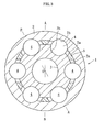
Fig. 2 andFig. 3 , a BJ (ball fixed joint) used in a drive shaft of an automobile and the like includes anouter member 2, aninner member 3,torque transmitting balls 4, and acage 5. Thecage 5 is interposed between theouter member 2 and theinner member 3. Thecage 5 is in spherical surface-contact with each of a spherical innercircumferential surface 2a of theouter member 2 and a spherical outercircumferential surface 3a of the inner member 3 (refer to, for example,Patent Document 1, Japanese Patent Laid-Open Publication No.Heisei 8-128454 - A plurality of curved guiding
grooves circumferential surface 2a of theouter member 2 and the outercircumferential surface 3a of theinner member 3. Center of curvatures OT0 and OT1 of the guidinggrooves outer member 2 and theinner member 3 are respectively at symmetrical positions to a joint center O (same as a spherical surface center of the spherical innercircumferential surface 2a of the outer member and the spherical outercircumferential surface 3a of the inner member). In other words, the center of curvature OT0 and the center of curvature OT1 are offset in an axial direction by equal distances in opposite directions from the joint center O. Therefore, a ball track formed by a guidinggroove 2b of theouter member 2 and a guidinggroove 3b of theinner member 3 is wedge-shaped, gradually widening from one axial direction towards the other. Eachtorque transmitting ball 4 is housed within this wedge-shaped ball track and load is transmitted between theouter member 2 and theinner member 3. Thecage 5 is assembled to hold alltorque transmitting balls 4 on a joint plane P (a plane perpendicular to a bisecting line of an operating angle). - Because the guiding
grooves torque transmitting balls 4 transmit load, axial force works on eachtorque transmitting ball 4. As a result, thetorque 1transmitting balls 4 try to fly out in a direction in which the guidinggrooves cage 5. Thecage 5 is firmly pressed against the spherical innercircumferential surface 2a of theouter member 2 and the spherical outercircumferential surface 3a of theinner member 3.
Patent Document 1: Japanese Patent Laid-Open Publication No.Heisei 8-128454 - Because the guiding
grooves torque transmitting balls 4 transmit a high load at an area in which the guiding groove is shallow (at a large operating angle), a contact ellipse caused by contact with thetorque transmitting balls 4 becomes large. The contact ellipse rides upwards onto a guiding groove shoulder at which stress is concentrated. There is risk of a chip being formed in the shoulder section. As a countermeasure, reduction of surface pressure by increasing a diameter of thetorque transmitting balls 4 and a pitch circle diameter (PCD) can be considered. However, a problem occurs in that an outer diameter of theouter member 2 increases and the constant velocity universal joint becomes larger. - Therefore, an object of the present invention is to provide a compact constant velocity universal joint that has high strength, and superior operability and durability.
- To achieve the above-described object, in the present invention, an offset angle of a ball track is set to 11.0° to 15.0°.
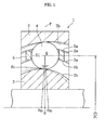
- Here, as shown in
Fig. 1 , an offset angle øT is a ∠OT0QOT1 formed by a center of curvature OT0 of a guidinggroove 2b of anouter component 2, an intersecting point Q between a joint plane P and a PCD, and a center of curvature OT1 of a guidinggroove 3b of aninner component 3. Conventionally, the offset angle øT is set to about 16.0° to 17.0°. However, in the present invention, the offset angle øT is smaller, in other words, 11.0°≤øT≤15.0°. - When the offset angle øT is small, as shown in
Fig. 1 , depths of guidinggrooves Fig. 1 shows when the groove depth of the guidinggrooves - On the other hand, when the offset angle is too small, durability and strength may deteriorate. Alternatively, a problem may occur regarding operability.
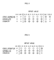
- Therefore, to determine a preferable offset angle øT range, tests for comparing cross operation, durability, and quasi-static torsional strength of a BJ were performed. The cross operation was evaluated by whether locking occurs when a shaft is bent to a maximum operating angle on a plane including opposing ball tracks in no load state, and subsequently bent on a plane perpendicular to the plane. Durability was evaluated under a load torque of 834N·m (85kgf·m), a rotational frequency of 230rpm, and an operating angle of 6°. Quasi-static torsional strength was evaluated under an operating angle of 40°, a rotational frequency of 2.5rpm, and a load torque increase rate of 0.05kN·m/rev. Test results are shown in
Fig. 4 . InFig. 4 , an × indicates a "problem ", a Δ indicates "deterioration",○ indicates "normal", and a ⊚ indicates "good" (same applies to the explanations below). - From
Fig. 4 , it can be understood that, when the offset angle is smaller than 11 °, a problem occurs in all cross operation, durability, and quasi-static torsional strength. When the offset angle is larger than 15.0°, durability and strength deteriorate. Therefore, to simultaneously satisfy operability, durability, and strength of the constant velocity universal joint, the offset angle øT is preferably set to 11.0° or more and 15.0° or less. - Regarding a UJ (undercut-free joint) as well, tests for comparing cross operation, durability, and quasi-static torsional strength were similarly performed. Aside from the quasi-static torsional strength test being performed at an operating angle of 50°, the tests are the same as those for the BJ. An offset angle øC of the cage is set to 1.8°.
- Test results are shown in
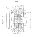
Fig. 5 . FromFig. 5 , it is determined that, in the UJ as well, when the offset angle øT of the ball track is set to 11.0° or more and 15.0° or less, operability, durability, and quasi-static torsional strength of the constant velocity universal joint can be simultaneously satisfied. - The offset angle øC of the cage in the UJ is preferably greater than 0° and 3.0° or less. An offset angle øC exceeding 0° is required to ensure allowable operating angle and strength of the cage. On the other hand, when øC exceeds 3.0°, heat generation significantly increases. Depth of the ball tracks decrease, causing a decline in life. Here, as shown in
Fig. 8 , the offset angle øC of the cage indicates a ∠OC0QOC1 formed by a spherical surface center OC0 of an outercircumferential surface 5a of acage 5, an intersecting point Q between a joint plane P and a PCD, and a spherical surface center OC1 of an innercircumferential surface 5b of thecage 5. The spherical surface center OC0 and the spherical surface center OC1 are offset in the axial direction by equal distances in opposite directions from the joint center O. An offset amount is less than the offset amount of the spherical surface centers OT0 and OT0 of the ball track. - The outer component is ordinarily manufactured by being heat treated (high frequency quenching and the like) after forging (for example, cold forging), and a finishing processing (grinding and the like) being further performed to achieve predetermined dimensions. In the present invention, because durability of the
cage 5 can be improved in a manner such as that described above, it is thought that no particular problems will occur regarding durability of an overall joint, even when the finishing processing, such as grinding, is omitted on any one of a spherical innercircumferential surface 2a and the guidinggrooves 2b of theouter component 2 and the spherical innercircumferential surface 2a or the guidinggrooves 2b is used as is with a forged surface (forging texture). - To demonstrate the above, a comparative test regarding an effect on durability the presence of grinding on the inner circumferential section of the outer component has was performed. Following results were obtained.
[Table 1] Durability Comparative Example 1 (grinding performed) ○ Comparative Example 2 (no grinding performed) Δ Invention 1 (øT =11.0°) ⊚ Invention 2 (øT = 15.0°) ⊚ - As is made clear by Table 1, in the
Inventions circumferential surface 2a and the guidinggrooves 2b) of theouter component 2 is omitted, an increase in durability can be seen compared to Comparative Examples 1 and 2 in which the offset angle øT is 16.0° (grinding is performed on the inner circumferential section of the Comparative Example 1, and grinding is not performed on the inner circumferential section of the Comparative Example 2). Therefore, when the offset angle øT is set to the above-described range, the grinding of the inner circumferential section (at least one of either the spherical innercircumferential surface 2a or the guidinggrooves 2b) of theouter component 2 can be omitted. Cost reduction can be achieved as a result of simplification of processing operations. - When the offset angle øT of the ball track is large, a force (axial force) by which the
torque transmitting ball 4 tries to fly outward in a direction in which the above-described wedge-shaped track space widens increases. Noise (slapping noise) of thetorque transmitting balls 4 striking thecage 5, the ball tracks, and the like becomes louder. Conventionally, thetorque transmitting balls 4 are pressed intopockets 51 of thecage 5 and a negative gap being formed therebetween. Thetorque transmitting balls 4 are held on the joint plane P with certainty, thereby reducing the slapping noise. However, when the torque transmitting balls are pressed within, because thetorque transmitting balls 4 move within thepockets 51 of thecage 5 in a pre-loaded state, heat generation and wear of thecage 5 occur. Because bending resistance of the constant velocity universal joint increases, bending becomes difficult to perform manually Effort may be required to be made when the constant velocity universal joint is assembled onto a vehicle and the like. - On the other hand, when the offset angle øT is smaller than that of the conventional product, the axial force weakens. It is thought that interference between the pockets and the
torque transmitting balls 4 can be a positive gap. - Table 2 is a study of a relationship between size of the offset angle øT and whether the slapping noise occurs. As is made clear from the results, the slapping noise occurs in a Comparative Example having the same offset angle øT as the conventional product (øT = 16. 0°). However, in the
Inventions 1 to 3 of which the offset angle øT is 11. 0°, 13. 0°, or 15. 0°, the slapping noise cannot be recognized (the interference is a positive gap in all Comparative Example and Inventions).[Table 2] Slapping Noise Comparative Example × Invention 1 (øT =11.0°) ○ Invention 2 (øT =13.0°) ○ Invention 3 (øT =15.0°) ○ - In this way, as a result of the offset angle øT being set within the above-described range, the interference between the pockets and the torque transmitting balls can be a positive gap while preventing the occurrence of the slapping noise. Therefore, heat generation and wear of the cage can be prevented, and durability can be improved. In addition, the bending resistance of the constant velocity universal joint can be reduced, and facilitation of assembly can be improved.
- The positive gap described here refers to a gap in the axial direction, as shown in
Fig. 6 . A width t is preferably 0 micrometers or more and 25 micrometers or less (the width of the gap in the diagram is exaggerated). - To determine grease suitable for being enclosed within the constant velocity universal joint of the present invention, grease having various friction coefficients µ were enclosed within the constant velocity universal joint, and durability tests were performed. The friction coefficient of the grease is measured using a Savan-type friction wear tester prescribed by JIS. Here, as shown in
Fig. 7 , the Savan-type friction wear tester is that in which a 1/4inch steel ball 12 is pressed against a 40ø×4mm rotation ring 11. When the friction coefficient is measured, therotation ring 11 is rotated at a circumferential speed of 108m/min. A load of 12.7N (1.3kgf) is applied. Grease is supplied to a front surface of therotation ring 11 via asponge 13 from a lower end of therotation ring 11. Movement of anairslide 14 supporting thesteel ball 12 is detected by aload cell 15, and the friction coefficient is measured. Friction coefficient measurement was performed 10 minutes after the start of the tests. - The durability tests were performed using a BJ having ball tracks with an offset angle øT of 13.0°, under a load torque of 834N·m (85kgf·m), a rotation frequency of 230rpm, and an operating angle of 6°. Test results are shown in Table 3.
[Table 3] Friction Coeflicient µ ThickeningAgent Durability 0.119 Li-type × 0.098 Li-type Δ 0.079 Urea-type Δ 0.070 Urea-type ○ 0.056 Urea-type ○ - It is determined, from Table 3, that grease having a friction coefficient µ of 0.070 or less, particularly that of which the thickening agent is a urea-type, can improve abrasion resistance and improve durability of the constant velocity universal joint.
- Among constituent elements of the constant velocity universal joint, when a protective layer is provided on a front surface section at which sliding friction occurs with a partner component, operability of the constant velocity universal joint can be improved. As the front surface section on which the protective layer is formed, a front surface section of the
cage 5 that comes into sliding contact with theouter component 2 and theinner component 3 can be given as an example. As the protective layer, a film effective in preventing or suppressing metallic contact between base materials, for example, a chemical conversion film, such as iron sulfide, or an absorbent film, such as molybdenum disulfide, can be considered. In this case, not only can any one of the films (for example, the chemical conversion film such as iron sulfide) be formed on the front surface section, but a composite film (the chemical conversion film such as iron sulfide + the absorbent film such as molybdenum disulfide) can be formed as well. - Table 4 shows a comparison of the effect on cross operation the presence of the protective layer has. The Comparative Example retains the grinding texture. In the Invention, the grinding texture is coated with molybdenum disulfide. As is made clear from Table 4, when the protective layer is formed, operability of the constant velocity universal joint can be improved. The test joints for both the Comparative Example and the Invention are BJ with an offset angle øT of 12.0°.
[Table 4] Cross operation Comparative Example: not coated ○ Invention: coated ⊚ - The constant velocity universal joint of the present invention has higher strength than a conventional product. Therefore, load capacity can be improved. In addition, the constant velocity universal joint has superior durability and can have a longer life. Moreover, the constant velocity universal joint has excellent durability and provides a stable torque transmitting function regardless of operating angle. These effects can be actualized without increasing the size of the constant velocity universal joint.
-
-
Fig. 1 is an enlarged cross-sectional view of a constant velocity universal joint (BJ); -
Fig. 2 is a vertical cross-sectional view of the constant velocity universal joint (BJ), showing a cross-section taken along A-O-A inFig. 3 ; -
Fig. 3 is a horizontal cross-sectional view of the constant velocity universal joint; -
Fig. 4 is a diagram of test results; -
Fig. 5 is a diagram of test results; -
Fig. 6 is an enlarged planar view of a cage; -
Fig. 7 is a cross-sectional view of a Savan-type friction wear tester; and -
Fig. 8 is a vertical cross-sectional view of a constant velocity universal joint (UJ), showing a cross-section taken along B-O-B inFig. 3 . - An embodiment of the present invention will be hereinafter described in detail with reference to the accompanying drawings.
- As shown in
Fig. 1 to Fig. 3 , a constant velocityuniversal joint 1 according to the embodiment includes an outer component 2 (outer member), an inner component 3 (inner member), a plurality of (ordinarily six)torque transmitting balls 4, and acage 5. In theouter component 2, a plurality of (ordinarily six) curved guidinggrooves 2b are formed on a spherical innercircumferential surface 2a in an axial direction. In theinner component 3, a plurality of (ordinarily six) curved guidinggrooves 3b are formed on a spherical outercircumferential surface 3a in the axial direction. Each of thetorque transmitting balls 4 are disposed on a ball track formed by a guidinggroove 2b of theouter component 2 and a guidinggroove 3b of theinner component 3 working in cooperation. Thecage 5 holds thetorque transmitting balls 4. - A center OT0 of the guiding
groove 2b of theouter component 2 and a center OT1 of the guidinggroove 3b of theinner component 3 are offset in the axial direction by equal distances in opposite directions from a joint center O (the center OT0 to an opening side of the joint, and the center OT1 to a back section side of the joint). Therefore, the ball track has a shape (wedge shape) that is wide on the opening side and gradually narrows towards the back section side. - A spherical surface center of an outer
circumferential surface 5a of thecage 5 and a spherical surface center of the innercircumferential surface 2a of theouter component 2 serving as a guiding surface of the outercircumferential surface 5a are both aligned with the joint center O. A spherical surface center of an innercircumferential surface 5b of thecage 5 and a spherical surface center of the outercircumferential surface 3a of theinner component 3 serving as a guiding surface of the innercircumferential surface 5b are both aligned with the joint center O. When theouter component 2 and theinner component 3 are angular-displaced by an angle θ, thetorque transmitting balls 4 guided by thecage 5 is always maintained within a bisecting surface (θ/2) of the angle θ, at any operating angle θ. Constant velocity of the joint ensured. - As shown in
Fig. 1 , an offset angle øT formed by the center of curvature OT0 of the guidinggroove 2b of theouter component 2, an intersecting point Q between a joint plane P and a PCD, and the center of curvature OT1 of the guidinggroove 3b of theinner component 3 is set to 11.0° to 15.0°. The offset angle øT is smaller than an offset angle (about 16.0°) of a conventional product. Therefore, the depths of the guidinggrooves cage 5 can be thickened, increased strength and increased life of the cage can be achieved. Furthermore, as described above, as long as the offset angle øT is within the range, operability can be favorably maintained. - The
outer component 2 and theinner component 3 are ordinarily heat-treated, such as by high frequency quenching, after cold-forging. Grinding is further performed, and theouter component 2 and theinner component 3 are finished having predetermined dimensions. In the present invention, the durability of thecage 5 improves in relation to the offset angle øT being smaller than that of the conventional product as described above. Therefore, even when a grinding process performed on the innercircumferential surface 2a of theouter component 2 is omitted, in practice, sufficient durability life can be ensured. From a similar perspective, grinding of the guidinggrooves 2b on theouter component 2 can also be omitted. In some cases, grinding of both the innercircumferential surface 2a and the guidinggrooves 2b can be omitted. - In addition, because force (axial force) by which the
torque transmitting balls 4 try to fly outward towards the joint opening side is weaker than that of the conventional product, slapping sounds generated as a result of the axial force of thetorque transmitting balls 4 are prevented or suppressed. Therefore, interference betweenpockets 51 and thetorque transmitting balls 4 can be a positive gap of 0 to 25 micrometers. Heat generation and wear of thecage 5 can be prevented and durability can be further improved. Moreover, bending resistance of the constant velocity universal joint can be reduced, improving facilitation of assembly. - A protective layer made from a chemical conversion film, such as iron sulfide, or an absorbent film, such as molybdenum disulfide, is formed on the outer
circumferential surface 5a and the innercircumferential surface 5b of thecage 5 to prevent or suppress metallic contact with theouter component 2 and theinner component 3. The protective layer is merely required to be interposed between two components between which relative sliding contact is made. Other than being formed on thecage 5 side, the protective layer can be formed on theouter component 2 side and theinner component 3 side. In other words, the protective layer can be formed on the innercircumferential surface 2a of theouter component 2 and the outercircumferential surface 3a of theinner component 3. The protective layer can also be formed on both thecage 5 side, and theouter component 2 side and theinner component 3 side. - Grease having a friction coefficient µ of 0.070 or less, measured using a Savan-type friction wear tester, is enclosed within the constant velocity universal joint.
-
Fig. 8 shows an embodiment in which the present invention is applied to an undercut-free joint (UJ). The center OT0 of the guidinggroove 2b of theouter component 2 and the center OT1 of the guidinggroove 3b of theinner component 3 are offset in the axial direction by equal distances in opposite directions from the joint center O (the center OT0 to the opening side of the joint, and the center OT1 to the back section side of the joint). In addition, a spherical surface center OC0 of the outercircumferential surface 5a of the cage 5 (same as the spherical surface center of the innercircumferential surface 2a of the outer component 2) and a spherical surface center OC1 of the innercircumferential surface 5b of the cage 5 (same as the spherical surface center of the outer circumferential surface of the inner component 3) are offset in the axial direction by equal distances in opposite directions from the joint center O (the center OC0 to the opening side of the joint, and the center OC1 to the back section side of the joint). The amount of offset of the outercircumferential surface 5a and the innercircumferential surface 5b of thecage 5 is less than the offset amount of the guidinggrooves -
Straight sections grooves 2b on theouter component 2 and an area U1 of the guidinggrooves 3b on theinner component 3. Thestraight section 2b1 of theouter component 2 is formed on one end side of the guidinggrooves 2b (an end section on the opening side of the joint). Thestraight section 3b1 of theinner component 3 is formed on the other end side of the guidinggrooves 3b (an end section on the back section side of the joint). - Each configuration of the present invention can be applied to the UJ as well, in manner similar to the BJ in
Fig. 1 to Fig. 3 . In this case, specific configurations are shared, aside from the above-described differences. Therefore, redundant explanations are omitted.
Claims (8)
- A fixed constant velocity universal joint including an outer component in which a plurality of guiding grooves extending in an axial direction are provided on a spherical inner circumferential surface, an inner component in which a plurality of guiding grooves extending in the axial direction are provided on a spherical outer circumferential surface, torque transmitting balls that are disposed on ball tracks formed by the guiding grooves on the outer component and the guiding grooves on the inner component forming pairs, and a cage that is guided by the spherical inner circumferential surface of the outer component and the spherical outer circumferential surface of the inner component and holds the torque transmitting balls, in which a center of curvature of a guiding grooves on the outer component and a center of curvature of a guiding groove on the inner component are offset in the axial direction in opposite directions from a joint center, the fixed constant velocity universal joint, wherein an offset angle of a ball track is 11.0° to 15.0°.
- A fixed constant velocity universal joint including an outer component in which a plurality of guiding grooves extending in an axial direction are provided on a spherical inner circumferential surface, an inner component in which a plurality of guiding grooves extending in the axial direction are provided on a spherical outer circumferential surface, torque transmitting balls that are disposed on ball tracks formed by the guiding grooves on the outer component and the guiding grooves on the inner component forming pairs, and a cage that is guided by the spherical inner circumferential surface of the outer component and the spherical outer circumferential surface of the inner component and holds the torque transmitting balls, in which a center of curvature of a guiding grooves on the outer component and a center of curvature of a guiding groove on the inner component are offset in the axial direction in opposite directions from a joint center, spherical centers of an outer circumferential surface and an inner circumferential surface of the cage are respectively offset in the axial direction in opposite directions from the joint center, and a straight section having a linear groove bottom is provided on each guiding groove on the outer component and the inner component, the fixed constant velocity universal joint, wherein an offset angle of a ball track is 11.0° to 15.0°.
- The constant velocity universal joint according to claim 2, wherein an offset angle of the cage is greater than 0° and less than 3.0°.
- The constant velocity universal joint according to claim 1 or 2, wherein, among the spherical inner circumferential surface and the guiding grooves of the outer component, at least one has a forged surface.
- The constant velocity universal joint according to claim 1 or 2, wherein, in the cage, an interference between a pocket housing a torque transmitting ball and the torque transmitting ball is a positive gap.
- The constant velocity universal joint according to claim 5, wherein the positive gap is 0 to 25 micrometers.
- The constant velocity universal joint according to claim 1 or 2, wherein grease having a friction coefficient of 0.070 or less is enclosed within.
- The constant velocity universal joint according to claim 1 or 2, wherein, among constituent elements of the constant velocity universal joint, a protective layer is formed on a front surface section at which sliding friction occurs with a partner side component.
Applications Claiming Priority (2)
| Application Number | Priority Date | Filing Date | Title |
|---|---|---|---|
| JP2006196321A JP2008025641A (en) | 2006-07-19 | 2006-07-19 | Constant velocity universal joint |
| PCT/JP2007/059239 WO2008010340A1 (en) | 2006-07-19 | 2007-04-27 | Constant velocity universal joint |
Publications (1)
| Publication Number | Publication Date |
|---|---|
| EP2042764A1 true EP2042764A1 (en) | 2009-04-01 |
Family
ID=38956675
Family Applications (1)
| Application Number | Title | Priority Date | Filing Date |
|---|---|---|---|
| EP07742674A Withdrawn EP2042764A1 (en) | 2006-07-19 | 2007-04-27 | Constant velocity universal joint |
Country Status (5)
| Country | Link |
|---|---|
| US (1) | US20100234115A1 (en) |
| EP (1) | EP2042764A1 (en) |
| JP (1) | JP2008025641A (en) |
| CN (1) | CN101490434A (en) |
| WO (1) | WO2008010340A1 (en) |
Cited By (2)
| Publication number | Priority date | Publication date | Assignee | Title |
|---|---|---|---|---|
| US8499457B2 (en) | 2008-11-06 | 2013-08-06 | Ntn Corporation | Fixed constant velocity universal joint, method of manufacturing fixed constant velocity universal joint, and bearing device adapted for use in driving wheel and using fixed constant velocity universal joint |
| US8529360B2 (en) | 2009-01-14 | 2013-09-10 | Ntn Corporation | Outer joint member for fixed constant velocity universal joint |
Families Citing this family (6)
| Publication number | Priority date | Publication date | Assignee | Title |
|---|---|---|---|---|
| JP5355876B2 (en) * | 2007-10-24 | 2013-11-27 | Ntn株式会社 | Constant velocity universal joint |
| JP2011133107A (en) * | 2009-11-26 | 2011-07-07 | Ntn Corp | Stationary constant-velocity universal joint |
| JP5912419B2 (en) * | 2011-06-07 | 2016-04-27 | Ntn株式会社 | Fixed constant velocity universal joint |
| DE112013004665T5 (en) * | 2012-11-19 | 2015-06-11 | Aisin Aw Co., Ltd. | automatic transmission |
| JP5502228B2 (en) * | 2013-07-16 | 2014-05-28 | Ntn株式会社 | Outer joint member of fixed type constant velocity universal joint |
| CN106215948B (en) * | 2016-07-06 | 2019-03-19 | 重庆大学 | A kind of preparation method of manganese dioxide composite magnetic catalyst |
Family Cites Families (11)
| Publication number | Priority date | Publication date | Assignee | Title |
|---|---|---|---|---|
| JPH08128454A (en) | 1994-11-02 | 1996-05-21 | Toyoda Mach Works Ltd | Constant velocity joint |
| US6120382A (en) * | 1995-12-26 | 2000-09-19 | Ntn Corporation | Constant velocity joint |
| JP2000230570A (en) * | 1999-02-10 | 2000-08-22 | Ntn Corp | Constant velocity universal joint |
| JP2002188653A (en) * | 2000-12-20 | 2002-07-05 | Ntn Corp | Constant velocity universal joint |
| US20030017877A1 (en) * | 2001-04-24 | 2003-01-23 | Masazumi Kobayashi | Constant velocity universal joint |
| JP4223358B2 (en) * | 2003-09-04 | 2009-02-12 | Ntn株式会社 | Fixed constant velocity universal joint |
| US7357724B2 (en) * | 2004-05-24 | 2008-04-15 | Ntn Corporation | Constant velocity joint |
| US7419433B2 (en) * | 2004-05-24 | 2008-09-02 | Ntn Corporation | ATV drive shaft and constant velocity joint |
| US8147342B2 (en) * | 2005-03-22 | 2012-04-03 | Ntn Corporation | Fixed-type constant-velocity universal joint |
| JP5322378B2 (en) * | 2005-09-28 | 2013-10-23 | ゲーカーエヌ ドライブライン ブルネック アクチエンゲゼルシャフト | Inner joint part for constant velocity joint, manufacturing method of inner joint part for constant velocity joint, and constant velocity joint |
| JP4994689B2 (en) * | 2006-03-27 | 2012-08-08 | Ntn株式会社 | Fixed constant velocity universal joint |
-
2006
- 2006-07-19 JP JP2006196321A patent/JP2008025641A/en not_active Withdrawn
-
2007
- 2007-04-27 EP EP07742674A patent/EP2042764A1/en not_active Withdrawn
- 2007-04-27 US US12/308,576 patent/US20100234115A1/en not_active Abandoned
- 2007-04-27 WO PCT/JP2007/059239 patent/WO2008010340A1/en not_active Ceased
- 2007-04-27 CN CNA2007800272945A patent/CN101490434A/en active Pending
Non-Patent Citations (1)
| Title |
|---|
| See references of WO2008010340A1 * |
Cited By (2)
| Publication number | Priority date | Publication date | Assignee | Title |
|---|---|---|---|---|
| US8499457B2 (en) | 2008-11-06 | 2013-08-06 | Ntn Corporation | Fixed constant velocity universal joint, method of manufacturing fixed constant velocity universal joint, and bearing device adapted for use in driving wheel and using fixed constant velocity universal joint |
| US8529360B2 (en) | 2009-01-14 | 2013-09-10 | Ntn Corporation | Outer joint member for fixed constant velocity universal joint |
Also Published As
| Publication number | Publication date |
|---|---|
| JP2008025641A (en) | 2008-02-07 |
| CN101490434A (en) | 2009-07-22 |
| WO2008010340A1 (en) | 2008-01-24 |
| US20100234115A1 (en) | 2010-09-16 |
Similar Documents
| Publication | Publication Date | Title |
|---|---|---|
| US20100234115A1 (en) | Constant velocity universal joint | |
| US8545337B2 (en) | Fixed uniform-motion universal joint | |
| US7097567B2 (en) | Constant velocity universal joint | |
| CN101606001B (en) | Constant velocity universal joint | |
| US20110034255A1 (en) | Fixed-type, constant-velocity universal joint | |
| US8388456B2 (en) | Fixed-type, constant-velocity universal joint | |
| US6506122B2 (en) | Constant velocity universal joint | |
| US9816565B2 (en) | Cage for constant velocity universal joint, fixed type constant velocity universal joint incorporating same, and drive shaft incorporating said fixed type constant velocity universal joint | |
| EP2908020B1 (en) | Fixed-type constant-velocity universal joint | |
| CN100529450C (en) | Fixed type constant velocity universal joint | |
| EP2602503B1 (en) | Fixed-type constant-velocity universal joint | |
| EP1548309B1 (en) | Fixed constant velocity universal joint | |
| EP2505863B1 (en) | Fixed type constant velocity universal joint | |
| EP1927775B1 (en) | Sliding-type constant velocity universal joint | |
| JP2000230570A (en) | Constant velocity universal joint | |
| EP2119930B1 (en) | Fixed constant velocity universal joint | |
| JP2002013544A (en) | Constant velocity universal joint | |
| CN101517255A (en) | Fixed constant velocity universal joint | |
| EP1510711A1 (en) | Constant velocity joint | |
| CN103748375B (en) | Constant velocity joint and manufacture method thereof | |
| JP2005226781A (en) | Constant velocity universal joint | |
| US20080248884A1 (en) | Constant Velocity Universal Joint | |
| JP3931020B2 (en) | Constant velocity universal joint | |
| CN118265853A (en) | Fixed constant velocity universal coupling | |
| KR20070022228A (en) | Constant velocity universal joint |
Legal Events
| Date | Code | Title | Description |
|---|---|---|---|
| PUAI | Public reference made under article 153(3) epc to a published international application that has entered the european phase |
Free format text: ORIGINAL CODE: 0009012 |
|
| 17P | Request for examination filed |
Effective date: 20090119 |
|
| AK | Designated contracting states |
Kind code of ref document: A1 Designated state(s): AT BE BG CH CY CZ DE DK EE ES FI FR GB GR HU IE IS IT LI LT LU LV MC MT NL PL PT RO SE SI SK TR |
|
| AX | Request for extension of the european patent |
Extension state: AL BA HR MK RS |
|
| STAA | Information on the status of an ep patent application or granted ep patent |
Free format text: STATUS: THE APPLICATION HAS BEEN WITHDRAWN |
|
| 18W | Application withdrawn |
Effective date: 20110325 |