EP2042757A1 - Bearing device - Google Patents
Bearing device Download PDFInfo
- Publication number
- EP2042757A1 EP2042757A1 EP07738370A EP07738370A EP2042757A1 EP 2042757 A1 EP2042757 A1 EP 2042757A1 EP 07738370 A EP07738370 A EP 07738370A EP 07738370 A EP07738370 A EP 07738370A EP 2042757 A1 EP2042757 A1 EP 2042757A1
- Authority
- EP
- European Patent Office
- Prior art keywords
- temperature sensor
- seal
- temperature
- bearing apparatus
- ring
- Prior art date
- Legal status (The legal status is an assumption and is not a legal conclusion. Google has not performed a legal analysis and makes no representation as to the accuracy of the status listed.)
- Withdrawn
Links
- 238000005096 rolling process Methods 0.000 claims abstract description 8
- 239000002120 nanofilm Substances 0.000 claims description 6
- 239000010409 thin film Substances 0.000 claims description 6
- 229910052751 metal Inorganic materials 0.000 claims description 4
- 239000002184 metal Substances 0.000 claims description 4
- 230000005856 abnormality Effects 0.000 description 5
- 238000000034 method Methods 0.000 description 3
- PXHVJJICTQNCMI-UHFFFAOYSA-N Nickel Chemical compound [Ni] PXHVJJICTQNCMI-UHFFFAOYSA-N 0.000 description 2
- 239000004696 Poly ether ether ketone Substances 0.000 description 2
- 239000004734 Polyphenylene sulfide Substances 0.000 description 2
- 239000007767 bonding agent Substances 0.000 description 2
- 230000002093 peripheral effect Effects 0.000 description 2
- BASFCYQUMIYNBI-UHFFFAOYSA-N platinum Chemical compound [Pt] BASFCYQUMIYNBI-UHFFFAOYSA-N 0.000 description 2
- 229920002530 polyetherether ketone Polymers 0.000 description 2
- 229920000139 polyethylene terephthalate Polymers 0.000 description 2
- 239000005020 polyethylene terephthalate Substances 0.000 description 2
- 229920000069 polyphenylene sulfide Polymers 0.000 description 2
- 229920003051 synthetic elastomer Polymers 0.000 description 2
- 239000005061 synthetic rubber Substances 0.000 description 2
- RYGMFSIKBFXOCR-UHFFFAOYSA-N Copper Chemical compound [Cu] RYGMFSIKBFXOCR-UHFFFAOYSA-N 0.000 description 1
- 229920000459 Nitrile rubber Polymers 0.000 description 1
- 239000004642 Polyimide Substances 0.000 description 1
- 229910052581 Si3N4 Inorganic materials 0.000 description 1
- 229920000800 acrylic rubber Polymers 0.000 description 1
- 239000000919 ceramic Substances 0.000 description 1
- 229910052802 copper Inorganic materials 0.000 description 1
- 239000010949 copper Substances 0.000 description 1
- 230000007423 decrease Effects 0.000 description 1
- 238000001514 detection method Methods 0.000 description 1
- 229920001971 elastomer Polymers 0.000 description 1
- 238000005516 engineering process Methods 0.000 description 1
- 230000001747 exhibiting effect Effects 0.000 description 1
- 229920001973 fluoroelastomer Polymers 0.000 description 1
- 238000007689 inspection Methods 0.000 description 1
- 238000004519 manufacturing process Methods 0.000 description 1
- 238000005259 measurement Methods 0.000 description 1
- 150000002739 metals Chemical class 0.000 description 1
- 229910052759 nickel Inorganic materials 0.000 description 1
- 230000000737 periodic effect Effects 0.000 description 1
- 229910052697 platinum Inorganic materials 0.000 description 1
- 229920000058 polyacrylate Polymers 0.000 description 1
- -1 polyethylene terephthalate Polymers 0.000 description 1
- 229920001721 polyimide Polymers 0.000 description 1
- 239000005060 rubber Substances 0.000 description 1
- 238000007789 sealing Methods 0.000 description 1
- 230000035945 sensitivity Effects 0.000 description 1
- HBMJWWWQQXIZIP-UHFFFAOYSA-N silicon carbide Chemical compound [Si+]#[C-] HBMJWWWQQXIZIP-UHFFFAOYSA-N 0.000 description 1
- 229910010271 silicon carbide Inorganic materials 0.000 description 1
- HQVNEWCFYHHQES-UHFFFAOYSA-N silicon nitride Chemical compound N12[Si]34N5[Si]62N3[Si]51N64 HQVNEWCFYHHQES-UHFFFAOYSA-N 0.000 description 1
- 229920002379 silicone rubber Polymers 0.000 description 1
- 239000004945 silicone rubber Substances 0.000 description 1
- 238000004544 sputter deposition Methods 0.000 description 1
- 238000001771 vacuum deposition Methods 0.000 description 1
- XLYOFNOQVPJJNP-UHFFFAOYSA-N water Substances O XLYOFNOQVPJJNP-UHFFFAOYSA-N 0.000 description 1
Images
Classifications
-
- G—PHYSICS
- G01—MEASURING; TESTING
- G01K—MEASURING TEMPERATURE; MEASURING QUANTITY OF HEAT; THERMALLY-SENSITIVE ELEMENTS NOT OTHERWISE PROVIDED FOR
- G01K13/00—Thermometers specially adapted for specific purposes
- G01K13/04—Thermometers specially adapted for specific purposes for measuring temperature of moving solid bodies
- G01K13/08—Thermometers specially adapted for specific purposes for measuring temperature of moving solid bodies in rotary movement
-
- F—MECHANICAL ENGINEERING; LIGHTING; HEATING; WEAPONS; BLASTING
- F16—ENGINEERING ELEMENTS AND UNITS; GENERAL MEASURES FOR PRODUCING AND MAINTAINING EFFECTIVE FUNCTIONING OF MACHINES OR INSTALLATIONS; THERMAL INSULATION IN GENERAL
- F16C—SHAFTS; FLEXIBLE SHAFTS; ELEMENTS OR CRANKSHAFT MECHANISMS; ROTARY BODIES OTHER THAN GEARING ELEMENTS; BEARINGS
- F16C19/00—Bearings with rolling contact, for exclusively rotary movement
- F16C19/52—Bearings with rolling contact, for exclusively rotary movement with devices affected by abnormal or undesired conditions
- F16C19/525—Bearings with rolling contact, for exclusively rotary movement with devices affected by abnormal or undesired conditions related to temperature and heat, e.g. insulation
-
- F—MECHANICAL ENGINEERING; LIGHTING; HEATING; WEAPONS; BLASTING
- F16—ENGINEERING ELEMENTS AND UNITS; GENERAL MEASURES FOR PRODUCING AND MAINTAINING EFFECTIVE FUNCTIONING OF MACHINES OR INSTALLATIONS; THERMAL INSULATION IN GENERAL
- F16C—SHAFTS; FLEXIBLE SHAFTS; ELEMENTS OR CRANKSHAFT MECHANISMS; ROTARY BODIES OTHER THAN GEARING ELEMENTS; BEARINGS
- F16C33/00—Parts of bearings; Special methods for making bearings or parts thereof
- F16C33/72—Sealings
- F16C33/76—Sealings of ball or roller bearings
- F16C33/78—Sealings of ball or roller bearings with a diaphragm, disc, or ring, with or without resilient members
- F16C33/784—Sealings of ball or roller bearings with a diaphragm, disc, or ring, with or without resilient members mounted to a groove in the inner surface of the outer race and extending toward the inner race
- F16C33/7843—Sealings of ball or roller bearings with a diaphragm, disc, or ring, with or without resilient members mounted to a groove in the inner surface of the outer race and extending toward the inner race with a single annular sealing disc
- F16C33/7853—Sealings of ball or roller bearings with a diaphragm, disc, or ring, with or without resilient members mounted to a groove in the inner surface of the outer race and extending toward the inner race with a single annular sealing disc with one or more sealing lips to contact the inner race
-
- F—MECHANICAL ENGINEERING; LIGHTING; HEATING; WEAPONS; BLASTING
- F16—ENGINEERING ELEMENTS AND UNITS; GENERAL MEASURES FOR PRODUCING AND MAINTAINING EFFECTIVE FUNCTIONING OF MACHINES OR INSTALLATIONS; THERMAL INSULATION IN GENERAL
- F16J—PISTONS; CYLINDERS; SEALINGS
- F16J15/00—Sealings
- F16J15/16—Sealings between relatively-moving surfaces
- F16J15/32—Sealings between relatively-moving surfaces with elastic sealings, e.g. O-rings
- F16J15/3296—Arrangements for monitoring the condition or operation of elastic sealings; Arrangements for control of elastic sealings, e.g. of their geometry or stiffness
-
- G—PHYSICS
- G01—MEASURING; TESTING
- G01M—TESTING STATIC OR DYNAMIC BALANCE OF MACHINES OR STRUCTURES; TESTING OF STRUCTURES OR APPARATUS, NOT OTHERWISE PROVIDED FOR
- G01M13/00—Testing of machine parts
- G01M13/04—Bearings
-
- F—MECHANICAL ENGINEERING; LIGHTING; HEATING; WEAPONS; BLASTING
- F16—ENGINEERING ELEMENTS AND UNITS; GENERAL MEASURES FOR PRODUCING AND MAINTAINING EFFECTIVE FUNCTIONING OF MACHINES OR INSTALLATIONS; THERMAL INSULATION IN GENERAL
- F16C—SHAFTS; FLEXIBLE SHAFTS; ELEMENTS OR CRANKSHAFT MECHANISMS; ROTARY BODIES OTHER THAN GEARING ELEMENTS; BEARINGS
- F16C19/00—Bearings with rolling contact, for exclusively rotary movement
- F16C19/02—Bearings with rolling contact, for exclusively rotary movement with bearing balls essentially of the same size in one or more circular rows
- F16C19/04—Bearings with rolling contact, for exclusively rotary movement with bearing balls essentially of the same size in one or more circular rows for radial load mainly
- F16C19/06—Bearings with rolling contact, for exclusively rotary movement with bearing balls essentially of the same size in one or more circular rows for radial load mainly with a single row or balls
-
- Y—GENERAL TAGGING OF NEW TECHNOLOGICAL DEVELOPMENTS; GENERAL TAGGING OF CROSS-SECTIONAL TECHNOLOGIES SPANNING OVER SEVERAL SECTIONS OF THE IPC; TECHNICAL SUBJECTS COVERED BY FORMER USPC CROSS-REFERENCE ART COLLECTIONS [XRACs] AND DIGESTS
- Y10—TECHNICAL SUBJECTS COVERED BY FORMER USPC
- Y10S—TECHNICAL SUBJECTS COVERED BY FORMER USPC CROSS-REFERENCE ART COLLECTIONS [XRACs] AND DIGESTS
- Y10S277/00—Seal for a joint or juncture
- Y10S277/919—Seal including electrical feature
Definitions
- the present invention relates generally to a bearing apparatus including a temperature sensor, and more particularly to a bearing apparatus suitable for use of an electrical component of an automobile, an alternator serving as an auxiliary engine, an intermediate pulley, an electromagnetic clutch for a car air-conditioner, a water pump, a hub unit, an electromagnetic clutch for a gas heat pump, a compressor, a linear guide apparatus, a ball screw, or the like.
- a bearing apparatus for supporting rotary parts has hitherto been, when once incorporated, subjected to none of periodic inspections in many cases, and in such a case it often happened that an interior thereof was inspected for the first time just when inconvenience occurred due to abnormality in temperature. Further, in the case of the bearings for a railway vehicle, a wind turbine, or the like, the bearing apparatus and other portions are decomposed and inspected after being used for a predetermined period of time. It is therefore difficult to predict the inconvenience due to the abnormality in temperature beforehand. An attempt (refer to Japanese Patent Laid-Open Publication No. 2002-130263 ) in this respect is made to detect the abnormality of the bearing in temperature before the critical inconvenience occurs by measuring a change of the temperature with a temperature sensor attached to the bearing apparatus.
- Japanese Patent Laid-Open Publication No. 2002-130263 involves using a stacked thermistor having a fixed thickness and is therefore restricted in terms of a fitting space, and it is difficult to measure a temperature of an originally-want-to-measure portion of the bearing. Further, a multiplicity of manufacturing processes thereof entails a considerable cost, which leads to the difficulty of being applied to the general-purpose bearings. Moreover, for example, if capable of directly measuring the temperature of the lip contacting with the rotary wheel, the abnormality in temperature can be detected beforehand. Generally, however, the lip is composed of a rubber and takes a thin-and-easy-to-flex shape, and it therefore follows that the temperature sensor is provided on the lip with the difficulty.
- a bearing apparatus comprises an outer ring, an inner ring, rolling elements disposed between the two rings, and a seal attached to one of the outer ring and the inner ring and extending toward the other ring, wherein a temperature sensor is fitted to the seal.
- the temperature sensor is fitted to the seal attached to one of the outer ring and the inner ring and extending toward the other ring, and hence a temperature of the seal contacting with the rotary wheel can be directly measured. Accordingly, if the temperature measured by the temperature sensor rapidly rises, this implies that some inconvenience might occur, and necessary countermeasures such as immediately stopping an apparatus using the bearing apparatus can be taken before the explicit inconvenience occurs.
- the prediction of the inconvenience can be further facilitated by fitting the temperature sensor to the lip portion of the seal.
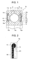
- FIG. 1 is a sectional view of a rolling bearing as viewed in a direction of an axis line, which is used in the present embodiment.
- a rolling bearing (angular ball bearing) 10 includes an outer ring 11, an inner ring 12, balls 13 serving as rolling element disposed between the two rings 11 and 12, a retainer 14 which retains the balls 13 at equal intervals in a peripheral direction, and seals 15, 15 disposed on both edge sides in the direction of the axis line between the two rings 11 and 12.
- the outer ring 11 has, along its inner periphery, a raceway surface 11a and fitting grooves 11b, 11b formed on both sides with the raceway surface 11a being interposed therebetween.
- the inner ring 12 has, along its outer periphery, a raceway surface 12a and fitting grooves 12b, 12b formed on both sides with the raceway surface 12a being interposed therebetween.
- the ball 13 may be composed of ceramic such as silicon nitride and silicon carbide.
- Each seal 15 includes a cored bar 15a constructed of a metal plate (SPCC, SECC, or the like) taking substantially a doughnut-like shape, and having a main portion excluding a hook, and the hook, a lip portion 15b composed of a synthetic rubber (such as a nitrile rubber, an acrylic rubber, a silicone rubber and a fluoro rubber) that is integrally formed by galvanization on an inner-diametrical side of the cored bar 15a, and a synthetic rubber fitting portion 15c that is integrally formed by galvanization on an outer-diametrical side of the cored bar 15a.
- the seal 15 is attached to the outer ring 11 by engaging with the fitting grooves 11b from outside while getting the fitting portion 15c elastically deformed. In such a state, a front end of the lip portion 15b contacts with the sealing groove 12b.
- temperature sensors TS are secured by a bonding agent to an inner side of the cored bar 15a and to an outer side of the lip portion 15b in one single seal 15. Though not illustrated, the wiring from the temperature sensor TS is drawn out to an external face of the seal 15 and to the outside through the outer ring 11. Note that the temperature sensor TS is depicted in exaggeration in terms of its thickness in FIG. 1 .
- FIG. 2 is an enlarged sectional view showing the temperature sensor TS in enlargement.
- the temperature sensor TS is a thermocouple constructed by stacking two types metal thin films M1, M2 over a high-molecular film F1 and covering these thin films with a homogeneous or heterogeneous high-molecular film F2 by thermocompression bonding or by use of a bonding agent.
- the high-molecular film be composed of PET (polyethylene terephthalate), PPS (poly phenylene sulfide), PI (polyimide), PEEK (polyetheretherketone), or the like.
- a thickness of the high-molecular film is preferably equal to or smaller than 1,000 ⁇ m in terms of considering a limited fitting space.
- a preferable method of forming the thin film is, though not limited in particular, a sputtering process and a vacuum deposition process.
- a combination of the metals of the thermocouple is not particularly limited, and one example is a combination of copper and nickel. It is desirable that a size of the measuring portion is equal to or larger than 1 ⁇ 10 -10 m 2 but equal to or smaller than 1 ⁇ 10 -6 m 2 .
- the seal 15 is attached with the temperature sensor TS, and hence the temperature of the lip portion 15b contacting with the inner ring 12 can be directly measured. Accordingly, if the temperature measured by the temperature sensor TS rapidly rises, this implies that some inconvenience might occur, and a necessary countermeasures such as immediately stopping the apparatus using the rolling bearing can be taken before the explicit inconvenience occurs.
- the temperature sensor TS may be, as depicted by dotted lines, disposed on the raceway surface 11a (portion A) of the outer ring 11 and an inner peripheral surface (portion B) other than the raceway surface 11a.
- the temperature sensor TS may be, without being limited to the thermocouple type, such a type, constructed of a thin film of platinum or the like, as to measure a change of resistance due to a change of the temperature.
- the bearing apparatus according to the present invention is useful as the apparatus capable of taking, because of some inconvenience occurring if the temperature measured by the temperature sensor rapidly rises, the necessary countermeasures such as immediately stopping the apparatus using the bearing apparatus before the explicit inconvenience occurs.
Landscapes
- Engineering & Computer Science (AREA)
- General Engineering & Computer Science (AREA)
- Mechanical Engineering (AREA)
- Physics & Mathematics (AREA)
- General Physics & Mathematics (AREA)
- Rolling Contact Bearings (AREA)
- Sealing Of Bearings (AREA)
Abstract
A bearing apparatus includes an outer ring (11), an inner ring (12), rolling elements (13) disposed between the two rings, and a seal (15) attached to one of the outer ring and the inner ring and extending toward the other ring. A temperature sensor is fitted to the seal, and hence a temperature of the seal contacting with a rotary wheel can be directly measured. Accordingly, if the temperature measured by the temperature sensor rapidly rises, this implies that some inconvenience might occur, and necessary countermeasures such as immediately stopping an apparatus using the bearing apparatus can be taken before the explicit inconvenience occurs.
Description
- The present invention relates generally to a bearing apparatus including a temperature sensor, and more particularly to a bearing apparatus suitable for use of an electrical component of an automobile, an alternator serving as an auxiliary engine, an intermediate pulley, an electromagnetic clutch for a car air-conditioner, a water pump, a hub unit, an electromagnetic clutch for a gas heat pump, a compressor, a linear guide apparatus, a ball screw, or the like.
- A bearing apparatus for supporting rotary parts has hitherto been, when once incorporated, subjected to none of periodic inspections in many cases, and in such a case it often happened that an interior thereof was inspected for the first time just when inconvenience occurred due to abnormality in temperature. Further, in the case of the bearings for a railway vehicle, a wind turbine, or the like, the bearing apparatus and other portions are decomposed and inspected after being used for a predetermined period of time. It is therefore difficult to predict the inconvenience due to the abnormality in temperature beforehand. An attempt (refer to Japanese Patent Laid-Open Publication No.
2002-130263 - However, the technology of Japanese Patent Laid-Open Publication No.
2002-130263 - It is an object of the present invention, which was devised in view of the problems in the prior arts, to provide a bearing apparatus including a downsized temperature sensor contrived to previously predict occurrence of the inconvenience due to the abnormality in temperature, without restricting a fitting space by ,for example, forming a thermocouple on a high-molecular thin film, showing a quick response because of being incorporated in whichever portions of the bearing, and exhibiting excellent mass-productivity.
- A bearing apparatus according to the present invention comprises an outer ring, an inner ring, rolling elements disposed between the two rings, and a seal attached to one of the outer ring and the inner ring and extending toward the other ring, wherein a temperature sensor is fitted to the seal.
- According to the present invention, the temperature sensor is fitted to the seal attached to one of the outer ring and the inner ring and extending toward the other ring, and hence a temperature of the seal contacting with the rotary wheel can be directly measured. Accordingly, if the temperature measured by the temperature sensor rapidly rises, this implies that some inconvenience might occur, and necessary countermeasures such as immediately stopping an apparatus using the bearing apparatus can be taken before the explicit inconvenience occurs.
- In particular, the prediction of the inconvenience can be further facilitated by fitting the temperature sensor to the lip portion of the seal.
-
-
FIG. 1 is a sectional view of a rolling apparatus as viewed in a direction of an axis line according to the present embodiment; and -
FIG. 2 is a sectional view showing a temperature sensor TS in enlargement inFIG. 1 . - Next, an embodiment of the present invention will hereinafter be described with reference to the drawings.
FIG. 1 is a sectional view of a rolling bearing as viewed in a direction of an axis line, which is used in the present embodiment. A rolling bearing (angular ball bearing) 10 includes anouter ring 11, aninner ring 12,balls 13 serving as rolling element disposed between the tworings retainer 14 which retains theballs 13 at equal intervals in a peripheral direction, andseals rings outer ring 11 has, along its inner periphery, araceway surface 11a andfitting grooves raceway surface 11a being interposed therebetween. Theinner ring 12 has, along its outer periphery, araceway surface 12a andfitting grooves raceway surface 12a being interposed therebetween. Theball 13 may be composed of ceramic such as silicon nitride and silicon carbide. - Each
seal 15 includes acored bar 15a constructed of a metal plate (SPCC, SECC, or the like) taking substantially a doughnut-like shape, and having a main portion excluding a hook, and the hook, alip portion 15b composed of a synthetic rubber (such as a nitrile rubber, an acrylic rubber, a silicone rubber and a fluoro rubber) that is integrally formed by galvanization on an inner-diametrical side of thecored bar 15a, and a syntheticrubber fitting portion 15c that is integrally formed by galvanization on an outer-diametrical side of thecored bar 15a. Theseal 15 is attached to theouter ring 11 by engaging with thefitting grooves 11b from outside while getting thefitting portion 15c elastically deformed. In such a state, a front end of thelip portion 15b contacts with the sealinggroove 12b. - In the present embodiment, temperature sensors TS are secured by a bonding agent to an inner side of the
cored bar 15a and to an outer side of thelip portion 15b in onesingle seal 15. Though not illustrated, the wiring from the temperature sensor TS is drawn out to an external face of theseal 15 and to the outside through theouter ring 11. Note that the temperature sensor TS is depicted in exaggeration in terms of its thickness inFIG. 1 . -
FIG. 2 is an enlarged sectional view showing the temperature sensor TS in enlargement. Referring toFIG. 2 , the temperature sensor TS is a thermocouple constructed by stacking two types metal thin films M1, M2 over a high-molecular film F1 and covering these thin films with a homogeneous or heterogeneous high-molecular film F2 by thermocompression bonding or by use of a bonding agent. Taking heat-resistance and elastic modulus into consideration, it is preferable that the high-molecular film be composed of PET (polyethylene terephthalate), PPS (poly phenylene sulfide), PI (polyimide), PEEK (polyetheretherketone), or the like. A thickness of the high-molecular film is preferably equal to or smaller than 1,000 µm in terms of considering a limited fitting space. A preferable method of forming the thin film is, though not limited in particular, a sputtering process and a vacuum deposition process. A combination of the metals of the thermocouple is not particularly limited, and one example is a combination of copper and nickel. It is desirable that a size of the measuring portion is equal to or larger than 1 × 10⁻¹⁰ m2 but equal to or smaller than 1 × 10⁻⁶m2. This is because it is difficult to perform a highly-accurate measurement, wherein a response upon measuring of the temperature declines if the size of the measuring portion exceeds 1 x 10⁻⁶m2, and detection sensitivity decreases if equal to or smaller than 1 x 10⁻¹⁰m2. - According to the present embodiment, the
seal 15 is attached with the temperature sensor TS, and hence the temperature of thelip portion 15b contacting with theinner ring 12 can be directly measured. Accordingly, if the temperature measured by the temperature sensor TS rapidly rises, this implies that some inconvenience might occur, and a necessary countermeasures such as immediately stopping the apparatus using the rolling bearing can be taken before the explicit inconvenience occurs. - The present invention has been discussed so far by way of the embodiment but should not be construed in the way of being limited to the embodiment and can be, as a matter of course, properly modified and improved. For example, the temperature sensor TS may be, as depicted by dotted lines, disposed on the
raceway surface 11a (portion A) of theouter ring 11 and an inner peripheral surface (portion B) other than theraceway surface 11a. Further, the temperature sensor TS may be, without being limited to the thermocouple type, such a type, constructed of a thin film of platinum or the like, as to measure a change of resistance due to a change of the temperature. - As described above, the bearing apparatus according to the present invention is useful as the apparatus capable of taking, because of some inconvenience occurring if the temperature measured by the temperature sensor rapidly rises, the necessary countermeasures such as immediately stopping the apparatus using the bearing apparatus before the explicit inconvenience occurs.
Claims (5)
- A bearing apparatus comprising:an outer ring;an inner ring;rolling elements disposed between said two rings; anda seal attached to one of said outer ring and said inner ring and extending toward said other ring,wherein a temperature sensor is fitted to said seal.
- A bearing apparatus according to claim 1, wherein said temperature sensor is fitted to a lip portion of said seal.
- A bearing apparatus according to claim 1 or 2, wherein said lip portion contacts with said outer ring or said inner ring.
- A bearing apparatus according to any one of claims 1 to 3, wherein said temperature sensor is fitted to a cored bar portion of said seal.
- A bearing apparatus according to any one of claims 1 to 4 wherein said temperature sensor is constructed of a high-molecular film and a metal thin film formed on said high-molecular film.
Applications Claiming Priority (2)
| Application Number | Priority Date | Filing Date | Title |
|---|---|---|---|
| JP2006190198A JP2008019897A (en) | 2006-07-11 | 2006-07-11 | Bearing device |
| PCT/JP2007/054898 WO2008007478A1 (en) | 2006-07-11 | 2007-03-13 | Bearing device |
Publications (1)
| Publication Number | Publication Date |
|---|---|
| EP2042757A1 true EP2042757A1 (en) | 2009-04-01 |
Family
ID=38923048
Family Applications (1)
| Application Number | Title | Priority Date | Filing Date |
|---|---|---|---|
| EP07738370A Withdrawn EP2042757A1 (en) | 2006-07-11 | 2007-03-13 | Bearing device |
Country Status (5)
| Country | Link |
|---|---|
| US (1) | US8221002B2 (en) |
| EP (1) | EP2042757A1 (en) |
| JP (1) | JP2008019897A (en) |
| CN (1) | CN101490429A (en) |
| WO (1) | WO2008007478A1 (en) |
Cited By (2)
| Publication number | Priority date | Publication date | Assignee | Title |
|---|---|---|---|---|
| EP2400603A4 (en) * | 2009-05-21 | 2014-08-06 | Panasonic Corp | GAS LASER OSCILLATING APPARATUS AND GAS LASER MACHINING APPARATUS |
| US12222007B2 (en) | 2021-11-24 | 2025-02-11 | Aktiebolaget Skf | Bearing unit with sensorized shield |
Families Citing this family (6)
| Publication number | Priority date | Publication date | Assignee | Title |
|---|---|---|---|---|
| DE102007036271A1 (en) * | 2007-07-31 | 2009-02-05 | Baumer Hübner GmbH | Encoder with monitoring of bearing wear and method |
| JP5423347B2 (en) * | 2009-11-24 | 2014-02-19 | パナソニック株式会社 | Gas laser oscillator and gas laser processing machine |
| WO2011135957A1 (en) * | 2010-04-26 | 2011-11-03 | 日本精工株式会社 | Rolling bearing |
| DE102013007983B4 (en) * | 2013-05-10 | 2015-09-03 | Audi Ag | Rolling device |
| CN107906005A (en) * | 2017-10-30 | 2018-04-13 | 安徽博古特机电科技有限公司 | A kind of compressor shaft bearing temperature control system |
| CN119412500B (en) * | 2024-09-27 | 2025-12-05 | 中铁工程装备集团有限公司 | Main drive sealing structure, manufacturing method and temperature monitoring method of tunnel boring machine |
Family Cites Families (7)
| Publication number | Priority date | Publication date | Assignee | Title |
|---|---|---|---|---|
| JPH07333073A (en) * | 1994-06-07 | 1995-12-22 | Casio Comput Co Ltd | Temperature sensor and temperature measuring instrument using the same |
| DE19912135A1 (en) * | 1998-05-20 | 1999-12-09 | Freudenberg Carl Fa | Shaft seal incorporates temperature sensor projecting into fluid retained by seal |
| JP2002130263A (en) | 2000-10-31 | 2002-05-09 | Ntn Corp | Bearing with temperature sensor |
| KR101018723B1 (en) * | 2003-02-14 | 2011-03-04 | 엔티엔 가부시키가이샤 | Mechanical parts using IC tag, quality control method and abnormal inspection system |
| JP2005024441A (en) * | 2003-07-04 | 2005-01-27 | Ntn Corp | Abnormality inspection system for bearing with ic tag sensor |
| JP4300924B2 (en) * | 2003-07-25 | 2009-07-22 | 日本精工株式会社 | Rolling bearing device |
| ATE474166T1 (en) * | 2007-02-27 | 2010-07-15 | Freudenberg Carl Kg | SEALING RING |
-
2006
- 2006-07-11 JP JP2006190198A patent/JP2008019897A/en active Pending
-
2007
- 2007-03-13 US US12/373,199 patent/US8221002B2/en active Active
- 2007-03-13 EP EP07738370A patent/EP2042757A1/en not_active Withdrawn
- 2007-03-13 CN CN200780026134.9A patent/CN101490429A/en active Pending
- 2007-03-13 WO PCT/JP2007/054898 patent/WO2008007478A1/en not_active Ceased
Non-Patent Citations (1)
| Title |
|---|
| See references of WO2008007478A1 * |
Cited By (2)
| Publication number | Priority date | Publication date | Assignee | Title |
|---|---|---|---|---|
| EP2400603A4 (en) * | 2009-05-21 | 2014-08-06 | Panasonic Corp | GAS LASER OSCILLATING APPARATUS AND GAS LASER MACHINING APPARATUS |
| US12222007B2 (en) | 2021-11-24 | 2025-02-11 | Aktiebolaget Skf | Bearing unit with sensorized shield |
Also Published As
| Publication number | Publication date |
|---|---|
| CN101490429A (en) | 2009-07-22 |
| WO2008007478A1 (en) | 2008-01-17 |
| US20090279823A1 (en) | 2009-11-12 |
| US8221002B2 (en) | 2012-07-17 |
| JP2008019897A (en) | 2008-01-31 |
Similar Documents
| Publication | Publication Date | Title |
|---|---|---|
| US8221002B2 (en) | Bearing apparatus | |
| US8313240B2 (en) | Sensorized bearing unit | |
| JP7362239B2 (en) | Bearing devices and spindle devices | |
| US9541128B2 (en) | Acoustic emission measurements of a bearing assembly | |
| US20180274682A1 (en) | Sealing device | |
| US11112348B2 (en) | Wear sensors for monitoring seal wear in bearing arrangements | |
| CN108291855A (en) | The diagnostic device of assembled state | |
| EP2023104A1 (en) | Bearing device and method of producing the same | |
| WO2011069519A1 (en) | Sensorized seal unit | |
| US8246252B2 (en) | Bearing apparatus | |
| JP2009191898A (en) | Bearing with sensor and manufacturing method thereof | |
| JP2020060227A (en) | Bearing device | |
| JP2007286002A (en) | Bearing device | |
| WO2019159838A1 (en) | Bearing device and spindle device | |
| CN113056620A (en) | Bearing device | |
| JP2007138974A (en) | Rolling bearing with temperature sensor | |
| US8070363B2 (en) | Bearing arrangement | |
| JP2008215568A (en) | Rolling bearing and manufacturing method thereof | |
| JP2008026102A (en) | Bearing device | |
| JP2003278781A (en) | Rolling bearing with sensor | |
| JP2008025691A (en) | Bearing device | |
| JP2006009825A (en) | Bearing with sensor | |
| JP2008025690A (en) | Bearing device | |
| JP2008064182A (en) | Bearing device | |
| JP2006029514A (en) | Bearing with sensor |
Legal Events
| Date | Code | Title | Description |
|---|---|---|---|
| PUAI | Public reference made under article 153(3) epc to a published international application that has entered the european phase |
Free format text: ORIGINAL CODE: 0009012 |
|
| 17P | Request for examination filed |
Effective date: 20090211 |
|
| AK | Designated contracting states |
Kind code of ref document: A1 Designated state(s): AT BE BG CH CY CZ DE DK EE ES FI FR GB GR HU IE IS IT LI LT LU LV MC MT NL PL PT RO SE SI SK TR |
|
| AX | Request for extension of the european patent |
Extension state: AL BA HR MK RS |
|
| STAA | Information on the status of an ep patent application or granted ep patent |
Free format text: STATUS: THE APPLICATION HAS BEEN WITHDRAWN |
|
| 18W | Application withdrawn |
Effective date: 20090529 |