EP2042748A1 - Stiffening ridge for solid wood - Google Patents
Stiffening ridge for solid wood Download PDFInfo
- Publication number
- EP2042748A1 EP2042748A1 EP09000196A EP09000196A EP2042748A1 EP 2042748 A1 EP2042748 A1 EP 2042748A1 EP 09000196 A EP09000196 A EP 09000196A EP 09000196 A EP09000196 A EP 09000196A EP 2042748 A1 EP2042748 A1 EP 2042748A1
- Authority
- EP
- European Patent Office
- Prior art keywords
- ridge
- profile
- strip
- strips
- solid wood
- Prior art date
- Legal status (The legal status is an assumption and is not a legal conclusion. Google has not performed a legal analysis and makes no representation as to the accuracy of the status listed.)
- Granted
Links
- 239000002023 wood Substances 0.000 title claims abstract description 41
- 239000007787 solid Substances 0.000 title claims abstract description 35
- 229910052782 aluminium Inorganic materials 0.000 claims description 8
- XAGFODPZIPBFFR-UHFFFAOYSA-N aluminium Chemical compound [Al] XAGFODPZIPBFFR-UHFFFAOYSA-N 0.000 claims description 8
- 230000008901 benefit Effects 0.000 description 7
- 238000000465 moulding Methods 0.000 description 7
- 238000009434 installation Methods 0.000 description 6
- 125000006850 spacer group Chemical group 0.000 description 5
- 229910000669 Chrome steel Inorganic materials 0.000 description 2
- XEEYBQQBJWHFJM-UHFFFAOYSA-N Iron Chemical compound [Fe] XEEYBQQBJWHFJM-UHFFFAOYSA-N 0.000 description 2
- 238000010276 construction Methods 0.000 description 2
- 241000701193 Mutellina purpurea Species 0.000 description 1
- 239000000853 adhesive Substances 0.000 description 1
- 230000001070 adhesive effect Effects 0.000 description 1
- 239000011248 coating agent Substances 0.000 description 1
- 238000000576 coating method Methods 0.000 description 1
- 230000001419 dependent effect Effects 0.000 description 1
- 238000011161 development Methods 0.000 description 1
- 230000018109 developmental process Effects 0.000 description 1
- 238000005553 drilling Methods 0.000 description 1
- 230000000694 effects Effects 0.000 description 1
- 238000003780 insertion Methods 0.000 description 1
- 230000037431 insertion Effects 0.000 description 1
- 229910052742 iron Inorganic materials 0.000 description 1
- 239000000463 material Substances 0.000 description 1
- 230000013011 mating Effects 0.000 description 1
- 229910052751 metal Inorganic materials 0.000 description 1
- 239000002184 metal Substances 0.000 description 1
- 238000000034 method Methods 0.000 description 1
- 238000012986 modification Methods 0.000 description 1
- 230000004048 modification Effects 0.000 description 1
- 230000003647 oxidation Effects 0.000 description 1
- 238000007254 oxidation reaction Methods 0.000 description 1
- 230000003014 reinforcing effect Effects 0.000 description 1
- 238000010079 rubber tapping Methods 0.000 description 1
- 239000003351 stiffener Substances 0.000 description 1
Images


Classifications
-
- B—PERFORMING OPERATIONS; TRANSPORTING
- B27—WORKING OR PRESERVING WOOD OR SIMILAR MATERIAL; NAILING OR STAPLING MACHINES IN GENERAL
- B27M—WORKING OF WOOD NOT PROVIDED FOR IN SUBCLASSES B27B - B27L; MANUFACTURE OF SPECIFIC WOODEN ARTICLES
- B27M3/00—Manufacture or reconditioning of specific semi-finished or finished articles
- B27M3/0013—Manufacture or reconditioning of specific semi-finished or finished articles of composite or compound articles
- B27M3/0066—Manufacture or reconditioning of specific semi-finished or finished articles of composite or compound articles characterised by tongue and groove or tap hole connections
-
- A—HUMAN NECESSITIES
- A47—FURNITURE; DOMESTIC ARTICLES OR APPLIANCES; COFFEE MILLS; SPICE MILLS; SUCTION CLEANERS IN GENERAL
- A47B—TABLES; DESKS; OFFICE FURNITURE; CABINETS; DRAWERS; GENERAL DETAILS OF FURNITURE
- A47B13/00—Details of tables or desks
- A47B13/08—Table tops; Rims therefor
-
- B—PERFORMING OPERATIONS; TRANSPORTING
- B27—WORKING OR PRESERVING WOOD OR SIMILAR MATERIAL; NAILING OR STAPLING MACHINES IN GENERAL
- B27M—WORKING OF WOOD NOT PROVIDED FOR IN SUBCLASSES B27B - B27L; MANUFACTURE OF SPECIFIC WOODEN ARTICLES
- B27M3/00—Manufacture or reconditioning of specific semi-finished or finished articles
- B27M3/0013—Manufacture or reconditioning of specific semi-finished or finished articles of composite or compound articles
- B27M3/0026—Manufacture or reconditioning of specific semi-finished or finished articles of composite or compound articles characterised by oblong elements connected laterally
-
- F—MECHANICAL ENGINEERING; LIGHTING; HEATING; WEAPONS; BLASTING
- F16—ENGINEERING ELEMENTS AND UNITS; GENERAL MEASURES FOR PRODUCING AND MAINTAINING EFFECTIVE FUNCTIONING OF MACHINES OR INSTALLATIONS; THERMAL INSULATION IN GENERAL
- F16B—DEVICES FOR FASTENING OR SECURING CONSTRUCTIONAL ELEMENTS OR MACHINE PARTS TOGETHER, e.g. NAILS, BOLTS, CIRCLIPS, CLAMPS, CLIPS OR WEDGES; JOINTS OR JOINTING
- F16B12/00—Jointing of furniture or the like, e.g. hidden from exterior
- F16B12/10—Jointing of furniture or the like, e.g. hidden from exterior using pegs, bolts, tenons, clamps, clips, or the like
- F16B12/12—Jointing of furniture or the like, e.g. hidden from exterior using pegs, bolts, tenons, clamps, clips, or the like for non-metal furniture parts, e.g. made of wood, of plastics
-
- F—MECHANICAL ENGINEERING; LIGHTING; HEATING; WEAPONS; BLASTING
- F16—ENGINEERING ELEMENTS AND UNITS; GENERAL MEASURES FOR PRODUCING AND MAINTAINING EFFECTIVE FUNCTIONING OF MACHINES OR INSTALLATIONS; THERMAL INSULATION IN GENERAL
- F16B—DEVICES FOR FASTENING OR SECURING CONSTRUCTIONAL ELEMENTS OR MACHINE PARTS TOGETHER, e.g. NAILS, BOLTS, CIRCLIPS, CLAMPS, CLIPS OR WEDGES; JOINTS OR JOINTING
- F16B2/00—Friction-grip releasable fastenings
- F16B2/02—Clamps, i.e. with gripping action effected by positive means other than the inherent resistance to deformation of the material of the fastening
- F16B2/14—Clamps, i.e. with gripping action effected by positive means other than the inherent resistance to deformation of the material of the fastening using wedges
-
- F—MECHANICAL ENGINEERING; LIGHTING; HEATING; WEAPONS; BLASTING
- F16—ENGINEERING ELEMENTS AND UNITS; GENERAL MEASURES FOR PRODUCING AND MAINTAINING EFFECTIVE FUNCTIONING OF MACHINES OR INSTALLATIONS; THERMAL INSULATION IN GENERAL
- F16B—DEVICES FOR FASTENING OR SECURING CONSTRUCTIONAL ELEMENTS OR MACHINE PARTS TOGETHER, e.g. NAILS, BOLTS, CIRCLIPS, CLAMPS, CLIPS OR WEDGES; JOINTS OR JOINTING
- F16B5/00—Joining sheets or plates, e.g. panels, to one another or to strips or bars parallel to them
- F16B5/0004—Joining sheets, plates or panels in abutting relationship
- F16B5/0032—Joining sheets, plates or panels in abutting relationship by moving the sheets, plates, or panels or the interlocking key parallel to the abutting edge
- F16B5/0052—Joining sheets, plates or panels in abutting relationship by moving the sheets, plates, or panels or the interlocking key parallel to the abutting edge the interlocking key acting as a dovetail-type key
-
- F—MECHANICAL ENGINEERING; LIGHTING; HEATING; WEAPONS; BLASTING
- F16—ENGINEERING ELEMENTS AND UNITS; GENERAL MEASURES FOR PRODUCING AND MAINTAINING EFFECTIVE FUNCTIONING OF MACHINES OR INSTALLATIONS; THERMAL INSULATION IN GENERAL
- F16B—DEVICES FOR FASTENING OR SECURING CONSTRUCTIONAL ELEMENTS OR MACHINE PARTS TOGETHER, e.g. NAILS, BOLTS, CIRCLIPS, CLAMPS, CLIPS OR WEDGES; JOINTS OR JOINTING
- F16B5/00—Joining sheets or plates, e.g. panels, to one another or to strips or bars parallel to them
- F16B5/06—Joining sheets or plates, e.g. panels, to one another or to strips or bars parallel to them by means of clamps or clips
- F16B5/0685—Joining sheets or plates to strips or bars
Definitions
- the invention relates to a ridge strip for solid wood.
- the inventive ridge strip is preferably used in furniture construction.
- Solid wood panels and solid wood in general tend to throw themselves.
- a so-called ridge strip in a ridge which runs transversely to the grain direction of the solid wood used.
- a dovetail-shaped groove is milled into the solid wood and then the ridge strip, which is also dovetail-shaped in cross section, inserted into the ridge, so that a positive dovetail connection is formed.
- the form fit is achieved that the solid wood panel is no longer discarded, but can still work in the longitudinal direction of the ridge strip.
- the ridge strip shown in this publication consists of two wedge strips, which are in the dovetail-shaped ridge are inserted.
- the two wedge strips can be braced by means of a double screw against the flanks of the dovetail-shaped ridge.
- the double screw has to a left-rotating and a right-rotating thread, wherein the left-hand thread of the double screw is guided in a provided in a wedge bar left-hand thread and the right-hand thread of the double screw in a provided in the second wedge bar right-hand thread.
- this embodiment has a number of disadvantages.
- specially designed double screws are required to push the two wedges apart.
- the two wedge strips must also have threaded holes for receiving the double screws in a fixed predetermined distance.
- it is disadvantageous in this embodiment that relatively little space is available for the tool for rotating the double screw and therefore the turning of the double screw is time-consuming. If it should turn out after inserting the ridge bar into the ridge that another double screw is required for clamping, then the entire ridge strip must first be relaxed again, then removed from the ridge, another double screw inserted and finally the ridge bar re-installed in the ridge and be tense. The installation of the ridge bar is therefore time consuming.
- the ridge strip comprises a first and a second holding part and a printing part arranged therebetween.
- the two holding parts are each provided with a profile section which rest under the force of the pressure part on the side walls of the groove, wherein the side walls of the groove overlap the two profile sections at least partially.
- An object of the invention is to provide a ridge strip for solid wood, in which it is sufficient if the Gratnut runs in solid wood only over part of the width of the solid wood.
- the ridge does not extend to the outer edges of the solid wood, the edges of the solid wood remain intact. For the viewer, therefore, the running in the solid wood groove is usually not visible. The viewer can only perceive the groove when he looks at the side of the solid wood on which the groove runs.
- the ridge strip according to the invention has the advantage that it can be easily and quickly mounted without the need for a special tool.
- the ridge strip for solid wood includes a first and a second profile strip, with one side each of the profile strips is curved so that the two profile strips brace by screwing into the ridge groove, which is embedded in solid wood, with the ridge groove.
- the two profile strips of the ridge strip are shaped such that they can form a positive connection with the ridge groove transversely to the longitudinal direction of the ridge.
- the positive connection can be achieved in particular with profiled strips, which are conically shaped in cross section.
- the profile strips together have a dovetail-shaped cross-section. This makes it easy to achieve a positive fit between the burr groove and the ridge bar.
- the two profiled strips are made of aluminum in the inventive ridge strip.
- Aluminum has a low weight, high flexural rigidity and is easy to process.
- the two profile strips may have an anodized coating.
- the two profile strips can have a cavity according to a further feature of the invention. This will be the two moldings easier and cheaper.
- a stiffening element can be provided in the cavity of the profile strip. This is particularly advantageous if the stiffness of the profile bar alone is insufficient.
- the profile strips can have a groove into which a profile element can be inserted.
- the profile element can be mounted in a simple manner accurately fit.
- the profile element can additionally serve as an additional stiffening element.
- FIG. 1 a section of a solid wood panel 1 is shown in cross-section, wherein the solid wood panel 1 has a dovetail-shaped ridge 6.
- a first profiled strip 2 is inserted in the Gratnut 6 .
- a second profiled strip 3 can be inserted over the opening of the dovetail-shaped ridge groove 6 in the ridge groove 6.
- the profile strip 3 is used so that the oblique outside 3.2 of the profile strip 3 comes to rest on the edge of the 6.2 Gratnut 6 and the base 3.1 of the profile strip 3 on the Gratnutgrund 6.1. This applies mutatis mutandis to the profiled strip 2.
- the two profile strips 2 and 3 can be clamped by means of a screw 7 against the ridge 6.
- the two opposite outer sides 4 of the two profiled strips 2 and 3 can, as shown in Figure 1, be corrugated.
- the corrugations of the outer sides 4 facilitate screwing in the screw 7.
- the number of screws used 7 for bracing the two moldings 2 and 3 depends on the length of the moldings and their geometry. The stiffer the profile strips are formed, the fewer screws 7 are required to achieve the necessary tension between the profile strips and the burr groove.
- the mounting positions of the screws 7 are not limited to a few predetermined by the ridge strip locations, but can be distributed over the entire length of the profile strips as required by the situation.
- the two profile strips 2 and 3 may be hollow or tubular. This ensures that the opposite outer walls 4, the at the same time serve as a guide for the screw 7, obtained a certain spring elasticity.
- the screw 7 may preferably be provided with a self-tapping thread, which leads to a deformation of the outer walls 4 of the profile strips 2 and 3 when screwing the screw 7.
- the measures mentioned are usually sufficient to prevent an independent turning out of the screw 7. If desired, however, the screw 7 can additionally be secured by means of adhesive against undesirable unscrewing.
- the two profile strips 2 and 3 have, as in the Figures 1 and 2 can be seen, in their interior a cavity 5 on. The purpose and the resulting benefits will be discussed further below.
- An anodized layer on the profiled strips 2 and 3 improves the lubricity between wood and profiled strip 2, 3.
- the anodized layer is an anodic oxidation layer. In addition, it prevents the wood from discolouring due to friction with the aluminum profile strips 2 and 3.
- FIG. 3 shown second mounting variant of the gratings differs from the in FIG. 2 shown first mounting form of the ridge strip in that the ridge 6 in FIG. 3 only so deep is that the two Make grooves 8 of the two profile strips 2 and 3 flush with the surface of the solid wood panel 1.
- This mounting variant is especially for in the FIGS. 7, 8, 9 and 12 shown embodiments of advantage.
- FIG. 4 shows a ridge strip, in which the two profile strips 2 and 3 each have a threaded bore 9 on its upper side. About the threaded holes 9 more elements with the two profile strips 2 and 3 can be screwed.
- stiffening elements 11 are located in the hollow chambers 5 of the two profile strips 2 and 3 stiffening elements 11. These are particularly advantageous if the two profile strips 2 and 3 do not have sufficient rigidity.
- the stiffening elements 11 may for example consist of iron, chrome steel or aluminum. They are, before the two profiled strips 2 and 3 are inserted into the ridge 6, inserted into the hollow chambers 5 of the profile strips 2 and 3.
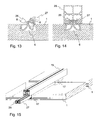
- the Gratnut 6 in the solid wood panel 1 is just so deep that the two grooves 8 of the two moldings 2 and 3 flush with the surface of the solid wood panel 1.
- a square profile 15 can be pushed into the two grooves 8.
- another shaped profile for example a triangular profile, can also be used.
- FIG. 8 is one to FIG. 7 alternative embodiment of the square profile 15 'shown.
- the two square profiles 15 and 15 ' can be used to attach other profiles, such as the profile 16, for example.
- the square profiles 15, 15 'and 16 can serve as additional stiffening elements. If the square profile 15 or 15 'is formed longer than the burr groove 6, the entire burr groove 6 can be covered with the square profile 15 or 15'. This has the advantage that the ridge 6 and the ridge bar are no longer recognizable to the viewer.
- FIG. 9 is a section of the tabletop with a ridge strip in cross section and in FIG. 15 a three-dimensional view of the tabletop with ridge bar shown.
- the ridge strip according to the invention offers a further advantage here. It serves in the in the Figures 9 and 15 illustrated embodiment additionally as a carrier element for spacers 17, which are each arranged between two boards 1. The spacers 17 ensure that, even if the individual solid wood boards 1 work, their distance from each other remains the same.
- the spacers 17 may be made of aluminum or any other weatherproof material.
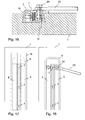
- the gratings as shown in FIG. 10 is shown to be provided with a specially trained stiffening element 18.
- a stiffening element 18 For mounting, it is only necessary that after insertion of the two profile strips 2 and 3 in the ridge groove 6, the stiffening element 18 is aligned relative to the two profile strips 2 and 3 and then screwed to them with the aid of the screw 7.
- a stiffening element 18 a U-shaped chrome steel or aluminum rail can be used.
- FIG. 10 Alternative to the embodiment in FIG. 10 can be used as a stiffening element and a squared timber 19, which is bolted via a correspondingly long screw 7 with the two profile strips 2 and 3.
- the ridge strip according to the invention also allows the use of a combination of wood and metal, as they are in FIG. 12 is shown.
- a cross-sectionally clamp-shaped rail 21 is inserted into a square timber 20 and screwed by a screw 22 with the timber 20.
- the squared timber 20 can be inserted by means of the rail 21 in the grooves of the two moldings 2 and 3. This will a screwless, invisible connection between timber 20 and solid wood panel 1 allows.
- FIG. 13 an alternative embodiment of the inventive ridge strip is shown.
- This has a first profile strip 26 and a second profile strip 27, which, as in FIG. 13 is shown, are screwed into the ridge 6.
- the two profile strips 26 and 27 each have a curved surface, the radius of which is calculated so that they can be screwed by turning about its longitudinal axis with defined limited force in the groove 6.
- the tension of the two ridge strips 26 and 27 with respect to the ridge groove 6 is effected in that the sum of the two radii of the ridge strips 26 and 27 is slightly larger than the opening of the ridge 6.
- the curvatures of the two profile strips 26 and 27 can be selected such that the profile strips 26 and 27 clamped in the groove groove 6 can no longer easily turn out of the groove groove 6 themselves.
- the two profiled strips 26 and 27 are screwed into the groove 6 beyond the point of maximum tension.
- the two profile strips 26 and 27 by a in FIG. 14 shown square section 28, which is pushed into the grooves 8 of the two profile strips 26 and 27, in addition to be secured against undesired unscrewing.
- additional profile elements can be attached to the square profile 28, which was produced for example from extruded aluminum.
- Tensioning cables are used.
- the attachment of such a tension cable is in FIG. 16 in cross section and in FIG. 18 shown in plan view.
- the end of a tensioning cable 23 is screwed by means of a screw 24 with the profiled strip 3.
- the nut 10 which is inserted at the corresponding location in the hollow chamber of the profile strip 3.
- the ridge 6 has a dovetailed cross-section.
- the shape of the profile strips 2, 3 and 26, 27 must be adapted to the changed cross-section of the ridge to ensure a positive connection between Gratnut and Moldings.
- the two profile strips 2 and 3 or 26 and 27 are formed symmetrically. This makes it possible, with a profile strip produced by the meter, which is cut to the desired length if necessary, to form the ridge strip according to the invention.
- Another advantage of the profiled strips described is that the profiled strips can be placed together without further ado and thus are arbitrarily extendable.
- the width of the ridge groove 6 is about 2/10 mm smaller sized than would be necessary for a stress-free installation of the two profile strips.
- the 2/10 mm undersize suffice to achieve with the help of the screw 7 sufficient tension between 6 and profile strips 2 and 3.
Landscapes
- Engineering & Computer Science (AREA)
- General Engineering & Computer Science (AREA)
- Life Sciences & Earth Sciences (AREA)
- Mechanical Engineering (AREA)
- Forests & Forestry (AREA)
- Wood Science & Technology (AREA)
- Manufacturing & Machinery (AREA)
- Mutual Connection Of Rods And Tubes (AREA)
- Connection Of Plates (AREA)
- Rod-Shaped Construction Members (AREA)
- Floor Finish (AREA)
- Wing Frames And Configurations (AREA)
- Chemical And Physical Treatments For Wood And The Like (AREA)
- Soil Working Implements (AREA)
Abstract
Description
Die Erfindung betrifft eine Gratleiste für Massivholz. Die erfindungsgemässe Gratleiste ist vorzugsweise im Möbelbau einsetzbar.The invention relates to a ridge strip for solid wood. The inventive ridge strip is preferably used in furniture construction.
Massive Holzplatten und Massivholz im Allgemeinen neigen dazu, sich zu werfen. Um dies zu vermeiden, wird im Möbelbau bei Massivholz eine sogenannte Gratleiste in eine Gratnut, die quer zur Faserrichtung des Massivholzes verläuft, eingesetzt. In der Regel wird dazu ins Massivholz eine schwalbenschwanzförmige Nut eingefräst und anschließend die Gratleiste, welche im Querschnitt ebenfalls schwalbenschwanzförmig geformt ist, in die Gratnut eingeschoben, so dass eine formschlüssige Schwalbenschwanzverbindung entsteht. Über den Formschluss wird erreicht, dass die Massivholzplatte sich nicht mehr verwirft, aber dennoch in Längsrichtung der Gratleiste arbeiten kann.Solid wood panels and solid wood in general tend to throw themselves. In order to avoid this, in furniture construction in solid wood a so-called ridge strip in a ridge, which runs transversely to the grain direction of the solid wood used. In general, a dovetail-shaped groove is milled into the solid wood and then the ridge strip, which is also dovetail-shaped in cross section, inserted into the ridge, so that a positive dovetail connection is formed. About the form fit is achieved that the solid wood panel is no longer discarded, but can still work in the longitudinal direction of the ridge strip.
Aus dem Stand der Technik
Aus der Druckschrift
Die Gratleiste umfasst ein erstes und ein zweites Halteteil sowie ein dazwischen angeordnetes Druckteil. Die beiden Halteteile sind jeweils mit einem Profilabschnitt versehen, die unter der Kraft des Druckteils an den Seitenwänden der Nut anliegen, wobei die Seitenwände der Nut die beiden Profilabschnitte wenigstens teilweise übergreifen.The ridge strip comprises a first and a second holding part and a printing part arranged therebetween. The two holding parts are each provided with a profile section which rest under the force of the pressure part on the side walls of the groove, wherein the side walls of the groove overlap the two profile sections at least partially.
Eine Aufgabe der Erfindung ist es, eine Gratleiste für Massivholz anzugeben, bei der es genügt, wenn die Gratnut im Massivholz lediglich über einen Teil der Breite des Massivholzes verläuft.An object of the invention is to provide a ridge strip for solid wood, in which it is sufficient if the Gratnut runs in solid wood only over part of the width of the solid wood.
Dadurch, dass sich die Gratnut nicht bis zu den Aussenkanten des Massivholzes erstreckt, bleiben die Kanten des Massivholzes unversehrt. Für den Betrachter ist daher die im Massivholz verlaufende Nut in der Regel nicht zu sehen. Der Betrachter kann die Nut nurmehr dann wahrnehmen, wenn er auf die Seite des Massivholzes blickt auf der die Nut verläuft.The fact that the ridge does not extend to the outer edges of the solid wood, the edges of the solid wood remain intact. For the viewer, therefore, the running in the solid wood groove is usually not visible. The viewer can only perceive the groove when he looks at the side of the solid wood on which the groove runs.
Zudem bietet die erfindungsgemäße Gratleiste den Vorteil, dass sie einfach und schnell montiert werden kann, ohne dass es dazu eines speziellen Werkzeugs bedarf.In addition, the ridge strip according to the invention has the advantage that it can be easily and quickly mounted without the need for a special tool.
Die Aufgabe wird durch eine Gratleiste für Massivholz mit den Merkmalen gemäß Patentanspruch 1 gelöst.The object is achieved by a ridge strip for solid wood with the features according to
Die Gratleiste für Massivholz umfasst eine erste und eine zweite Profilleiste, wobei jeweils eine Seite der Profilleisten derart gekrümmt ist, dass sich die beiden Profilleisten durch ein Eindrehen in die Gratnut, welche im Massivholz eingelassen ist, mit der Gratnut verspannen.The ridge strip for solid wood includes a first and a second profile strip, with one side each of the profile strips is curved so that the two profile strips brace by screwing into the ridge groove, which is embedded in solid wood, with the ridge groove.
Vorteilhafte Weiterbildungen der Erfindung ergeben sich aus den in den abhängigen Patentansprüchen angegebenen Merkmalen.Advantageous developments of the invention will become apparent from the features indicated in the dependent claims.
Bei einer ersten Ausführungsform der Erfindung sind die beiden Profilleisten der Gratleiste derart geformt, dass sie mit der Gratnut quer zur Längsrichtung der Gratnut einen Formschluss bilden können.In a first embodiment of the invention, the two profile strips of the ridge strip are shaped such that they can form a positive connection with the ridge groove transversely to the longitudinal direction of the ridge.
Der Formschluss kann insbesondere mit Profilleisten erreicht werden, die im Querschnitt konisch geformt sind.The positive connection can be achieved in particular with profiled strips, which are conically shaped in cross section.
Bei einer weiteren Ausführungsform der Erfindung weisen die Profilleisten zusammen einen schwalbenschwanzförmigen Querschnitt auf. Damit lässt sich auf einfache Art und Weise zwischen der Gratnut und der Gratleiste ein Formschluss erreichen.In a further embodiment of the invention, the profile strips together have a dovetail-shaped cross-section. This makes it easy to achieve a positive fit between the burr groove and the ridge bar.
Zudem ist es von Vorteil, wenn bei der erfindungsgemäßen Gratleiste die beiden Profilleisten aus Aluminium gefertigt sind. Aluminium hat ein geringes Gewicht, hat eine hohe Biegesteifigkeit und ist einfach weiterverarbeitbar.In addition, it is advantageous if the two profiled strips are made of aluminum in the inventive ridge strip. Aluminum has a low weight, high flexural rigidity and is easy to process.
Darüber hinaus können die beiden Profilleisten eine Eloxalschicht aufweisen.In addition, the two profile strips may have an anodized coating.
Die beiden Profilleisten können nach einem weiteren Merkmal der Erfindung einen Hohlraum aufweisen. Dadurch werden die beiden Profilleisten leichter und kostengünstiger.The two profile strips can have a cavity according to a further feature of the invention. This will be the two moldings easier and cheaper.
In einer weiteren Ausführungsform kann im Hohlraum der Profilleiste ein Versteifungselement vorgesehen sein. Dies ist insbesondere dann von Vorteil, wenn die Steifigkeit der Profilleiste allein nicht ausreicht.In a further embodiment, a stiffening element can be provided in the cavity of the profile strip. This is particularly advantageous if the stiffness of the profile bar alone is insufficient.
Darüber hinaus können die Profilleisten eine Nut aufweisen, in die ein Profilelement einschiebbar ist. Mit Hilfe der Nuten kann das Profilelement auf einfache Art und Weise passgenau montiert werden. Das Profilelement kann zusätzlich als zusätzliches Versteifungselement dienen.In addition, the profile strips can have a groove into which a profile element can be inserted. With the help of the grooves, the profile element can be mounted in a simple manner accurately fit. The profile element can additionally serve as an additional stiffening element.
Im Folgenden wird die Erfindung mit mehreren Ausführungsbeispielen anhand von 18 Figuren weiter erläutert.
Figur 1- zeigt, wie die Gratleiste in die Gratnut, die im Massivholz eingelassen ist, eingesetzt wird.
Figur 2- zeigt die montierte Gratleiste und die Massivholzplatte in einer ersten Montagevariante im Querschnitt.
Figur 3- zeigt eine zweite Montagevariante der Gratleiste im Querschnitt.
Figur 4- zeigt die Gratleiste mit zwei Gewindebohrungen im Querschnitt.
Figur 5- zeigt die Gratleiste mit zwei eingesetzten Muttern im Querschnitt.
Figur 6- zeigt die Gratleiste mit zwei eingesetzten Versteifungselementen im Querschnitt.
Figur 7- zeigt die zweite Montagevariante der Gratleiste mit einem aufgesetzten Vierkantprofil im Querschnitt.
Figur 8- zeigt die Gratleiste in der zweiten Montagevariante mit einer etwas anders ausgebildeten Vierkantprofilleiste im Querschnitt.
- Figur 9
- zeigt die in
Figur 7 Figur 10- zeigt die erste Montagevariante der Gratleiste mit einem auf der Oberseite der Gratleiste aufgesetzten Verstärkungselement im Querschnitt.
Figur 11- zeigt die erste Montagevariante der Gratleiste in Verbindung mit einem aufgesetzten Vierkantholz.
- Figur 12
- zeigt die zweite Montagevariante der Gratleiste mit einem aufgesetzten Versteifungselement im Querschnitt.
- Figur 13
- zeigt eine alternative Ausführungsform der Gratleiste im Querschnitt.
- Figur 14
- zeigt die alternative Ausführungsform der Gratleiste mit einem aufgeschobenen Vierkantprofil im montierten Zustand.
Figur 15- zeigt in einer dreidimensionalen Ansicht eine mögliche Montagevariante der Gratleiste.
Figur 16- zeigt die Gratleiste mit einem an ihr befestigten Spannseil.
Figur 17- zeigt in der Draufsicht eine mögliche Ausführungsform der montierten Gratleiste in Verbindung mit einem Vierkantprofil.
Figur 18- zeigt eine zweite Ausführungsform der montierten Gratleiste in Verbindung mit dem montierten Spannseil.
- FIG. 1
- shows how the ridge bar is inserted into the ridge, which is embedded in the solid wood.
- FIG. 2
- shows the mounted ridge strip and the solid wood panel in a first assembly variant in cross section.
- FIG. 3
- shows a second mounting variant of the ridge strip in cross section.
- FIG. 4
- shows the ridge strip with two threaded holes in cross section.
- FIG. 5
- shows the ridge strip with two nuts inserted in cross-section.
- FIG. 6
- shows the ridge strip with two inserted stiffening elements in cross section.
- FIG. 7
- shows the second installation variant of the ridge strip with an attached square profile in cross section.
- FIG. 8
- shows the ridge strip in the second mounting variant with a slightly different trained square profile strip in cross section.
- FIG. 9
- shows the in
FIG. 7 illustrated mounting variant in conjunction with an additional spacer. - FIG. 10
- shows the first installation variant of the gratings with a patch on the top of the gratings reinforcing element in cross section.
- FIG. 11
- shows the first installation variant of the ridge strip in conjunction with an attached square wood.
- FIG. 12
- shows the second mounting variant of the ridge strip with an attached stiffening element in cross section.
- FIG. 13
- shows an alternative embodiment of the ridge strip in cross section.
- FIG. 14
- shows the alternative embodiment of the gratings with a deferred square profile in the assembled state.
- FIG. 15
- shows in a three-dimensional view a possible installation variant of the ridge strip.
- FIG. 16
- shows the ridge bar with a tensioning rope attached to it.
- FIG. 17
- shows in plan view a possible embodiment of the mounted ridge strip in conjunction with a square profile.
- FIG. 18
- shows a second embodiment of the mounted ridge strip in conjunction with the mounted tensioning cable.
In
Grundsätzlich arbeitet eine Massivholzplatte je nach Temperatur- und Feuchtigkeit mehr oder weniger stark, was bei der im Stand der Technik
Mit Hilfe der Riffelungen der Außenseiten 4 der beiden Profilleisten 2 und 3 wird ein unerwünschtes selbstständiges Ausdrehen der Schraube 7 zu erschwert. Als weitere Maßnahme können die beiden Profilleisten 2 und 3 hohl oder rohrartig ausgeführt sein. Dadurch wird erreicht, dass die sich gegenüberliegenden Außenwände 4, die gleichzeitig als Führung für die Schraube 7 dienen, eine gewisse Federelastizität erhalten. Zudem kann die Schraube 7 vorzugsweise mit einem selbst schneidenden Gewinde versehen sein, welches beim Eindrehen der Schraube 7 zu einer Verformung der Außenwände 4 der Profilleisten 2 und 3 führt. Des weiteren ist es von Vorteil, die Auflagefläche des Schraubenkopfs auf den Oberseiten der beiden Profilleisten 2 und 3 möglichst gross zu machen und die Unterseite des Schraubenkopfs flach, d.h. nicht konisch, auszubilden. Dadurch wird die Reibung zwischen Schraube 7 und den Profilleisten 2 und 3 erhöht. Die genannten Maßnahmen sind in der Regel ausreichend, um ein selbstständiges Ausdrehen der Schraube 7 zu verhindern. Falls gewünscht, kann die Schraube 7 jedoch zusätzlich mittels Klebstoff gegen ein unerwünschtes Ausdrehen gesichert werden.With the help of the corrugations of the
Die beiden Profilleisten 2 und 3 weisen, wie in den
Eine Eloxalschicht auf den Profilleisten 2 und 3 verbessert die Gleitfähigkeit zwischen Holz und Profilleiste 2, 3. Die Eloxalschicht ist eine durch anodische Oxidation aufgebrachte Schicht. Zudem verhindert sie, dass sich das Holz durch Reibung mit den Aluminiumprofilleisten 2 und 3 verfärbt.An anodized layer on the profiled
Die in
Statt der Gewindebohrungen 9 können, wie in
Bei der in
Bei der in
In
Bei Tischen, deren Tischplatte aus Massivholz besteht und die im Freien aufgestellt werden, kann es wünschenswert sein, die einzelnen Massivholzbretter der Tischplatte mittels einer Fuge voneinander beabstandet auszurichten. In
Insbesondere bei Situationen, bei denen eine außerordentlich hohe Verformungssteifigkeit erforderlich ist, kann die Gratleiste, wie dies in
Alternativ zum Ausführungsbeispiel in
Die erfindungsgemäße Gratleiste ermöglicht auch die Verwendung einer Kombination aus Holz und Metall, wie sie wie in
In
Insbesondere bei großen Tischen kann es erforderlich sein, eine kreuzweise verlaufende zusätzliche Versteifung der Tischplatte vorzusehen. Hierzu können beispielsweise Spannseile verwendet werden. Die Befestigung eines solchen Spannseiles ist in
Es ist nicht zwingend erforderlich, dass die Gratnut 6 einen schwalbenschwanzförmigen Querschnitt aufweist. Es sind auch andere Gratnut-Querschnitte denkbar, wobei dann die Form der Profilleisten 2, 3 bzw. 26, 27 an den geänderten Querschnitt der Gratnut angepasst werden muss, um eine formschlüssige Verbindung zwischen Gratnut und Profilleisten zu gewährleisten.It is not mandatory that the
Vorteilhafterweise sind die beiden Profilleisten 2 und 3 bzw. 26 und 27 symmetrisch ausgebildet. Dadurch wird es möglich, mit einer als Meterware hergestellten Profilleiste, die bedarfsweise auf die gewünschte Länge abgelängt wird, die erfindungsgemäße Gratleiste zu bilden. Ein weiterer Vorteil der beschriebenen Profilleisten besteht darin, dass die Profilleisten ohne weiteres aneinandergesetzt werden können und damit beliebig verlängerbar sind.Advantageously, the two
In einer Ausführungsform der Gratleiste ist die Breite der Gratnut 6 ca. 2/10 mm kleiner bemessen als dies für eine spannungsfreie Montage der beiden Profilleisten nötig wäre. Die 2/10 mm Untermass genügen, um mit Hilfe der Schraube 7 eine ausreichende Verspannung zwischen Gratnut 6 und Profilleisten 2 und 3 zu erreichen.In one embodiment of the ridge strip, the width of the
Wird die Gratnut 6 so tief ausgeführt, dass die beiden Profilleisten 2 und 3 mit der Massivholzplatte 1 bündig abschließen, so hat dies insbesondere bei Tischen mit Auszugsplatten Vorteile, da es bei dieser Montagevariante keine hervorstehenden Bauteile gibt.If the
Die vorhergehende Beschreibung der Ausführungsbeispiele gemäss der vorliegenden Erfindung dient nur zu illustrativen Zwecken und nicht zum Zwecke der Beschränkung der Erfindung. Im Rahmen der Erfindung sind verschiedene Änderungen und Modifikationen möglich, ohne den Umfang der Erfindung sowie ihre Äquivalente zu verlassen.The foregoing description of the embodiments according to the present invention is for illustrative purposes only, and not for the purpose of limiting the invention. Various changes and modifications are possible within the scope of the invention without departing from the scope of the invention and its equivalents.
- 11
- Massivholzsolid wood
- 22
- erste Profilleistefirst profile bar
- 33
- zweite Profilleistesecond profile strip
- 3.13.1
- Unterseite der ProfilleisteBottom of the profile strip
- 3.23.2
- schräge Seite der Profilleistesloping side of the profile strip
- 44
- Riffelung auf der Aussenseite der ProfilleisteCorrugation on the outside of the profile strip
- 55
- Hohlraumcavity
- 66
- GratnutGratnut
- 6.16.1
- Nutgrundgroove base
- 6.26.2
- Nutflankeflank
- 77
- Schraubescrew
- 88th
- Nut in der ProfilleisteGroove in the profile strip
- 99
- Bohrungdrilling
- 1010
- Muttermother
- 1111
- Versteifungselementstiffener
- 1515
- VierkantprofilSquare profile
- 15'15 '
- VierkantprofilSquare profile
- 1616
- weiteres Vierkantprofilanother square profile
- 1717
- Abstandshalterspacer
- 1818
- U-ProfilU-profile
- 1919
- VierkantholzleisteSquare wood strip
- 2020
- VierkantholzleisteSquare wood strip
- 2121
- VierkantprofilSquare profile
- 2222
- weitere Schraubeanother screw
- 2323
- Spannseiltether
- 2424
- Schraubescrew
- 2626
- erste Profilleistefirst profile bar
- 2727
- zweite Profilleistesecond profile strip
- 2828
- VierkantprofilSquare profile
Claims (7)
bei der die beiden Profilleisten (26, 27) derart ausgebildet sind, dass sie mit der Gratnut (6) quer zur Längsrichtung der Gratnut (6) einen Formschluss bilden können.Gratbar according to claim 1,
in which the two profiled strips (26, 27) are designed in such a way that they can form a positive connection with the grating groove (6) transversely to the longitudinal direction of the grating groove (6).
bei der die Profilleisten (26, 27) eine Nut (8) aufweisen, in die ein Profilelement (28) einschiebbar ist.Gratleiste according to claim 1 or 2,
in which the profile strips (26, 27) have a groove (8) into which a profile element (28) can be inserted.
bei der die beiden Profilleisten (26, 27) zusammen einen schwalbenschwanzförmigen Querschnitt aufweisen.Gratleiste according to claim 1, 2 or 3,
in which the two profile strips (26, 27) together have a dovetail-shaped cross-section.
bei der die Profilleisten (2, 3) aus Aluminium gefertigt sind.Gratleiste according to one of the claims 1 to 4,
in which the profile strips (2, 3) are made of aluminum.
bei der die Profilleisten (2, 3) eine Eloxalschicht aufweisen.Gratbar according to claim 5,
in which the profile strips (2, 3) have an anodized layer.
Applications Claiming Priority (1)
| Application Number | Priority Date | Filing Date | Title |
|---|---|---|---|
| EP04405347A EP1602836B1 (en) | 2004-06-04 | 2004-06-04 | Stiffening ridge for solid wood |
Related Parent Applications (2)
| Application Number | Title | Priority Date | Filing Date |
|---|---|---|---|
| EP04405347A Division EP1602836B1 (en) | 2004-06-04 | 2004-06-04 | Stiffening ridge for solid wood |
| EP04405347.8 Division | 2004-06-04 |
Publications (2)
| Publication Number | Publication Date |
|---|---|
| EP2042748A1 true EP2042748A1 (en) | 2009-04-01 |
| EP2042748B1 EP2042748B1 (en) | 2012-12-26 |
Family
ID=34932134
Family Applications (2)
| Application Number | Title | Priority Date | Filing Date |
|---|---|---|---|
| EP04405347A Expired - Lifetime EP1602836B1 (en) | 2004-06-04 | 2004-06-04 | Stiffening ridge for solid wood |
| EP09000196A Expired - Lifetime EP2042748B1 (en) | 2004-06-04 | 2004-06-04 | Stiffening ridge for solid wood |
Family Applications Before (1)
| Application Number | Title | Priority Date | Filing Date |
|---|---|---|---|
| EP04405347A Expired - Lifetime EP1602836B1 (en) | 2004-06-04 | 2004-06-04 | Stiffening ridge for solid wood |
Country Status (4)
| Country | Link |
|---|---|
| EP (2) | EP1602836B1 (en) |
| AT (1) | ATE421642T1 (en) |
| DE (1) | DE502004008911D1 (en) |
| ES (1) | ES2321612T3 (en) |
Cited By (1)
| Publication number | Priority date | Publication date | Assignee | Title |
|---|---|---|---|---|
| RU2720460C1 (en) * | 2018-10-26 | 2020-04-30 | Юнилумин Груп Ко., Лтд. | Fixture for boxes |
Families Citing this family (4)
| Publication number | Priority date | Publication date | Assignee | Title |
|---|---|---|---|---|
| US20160017907A1 (en) * | 2014-07-16 | 2016-01-21 | Kevin Patrick Ryan | Split wedge dovetail dowel |
| DE102015005042A1 (en) * | 2015-04-21 | 2016-10-27 | Mjm Design & Technik Gmbh | Two- or multi-part gratings with one- or two-sided dovetail formation, for attaching and / or joining workpieces in particular suitable for the production and installation of wall, ceiling and floor elements for timber structures, preferably using renewable raw materials |
| AT524417B1 (en) * | 2021-06-08 | 2022-06-15 | Erwin Kitzmueller | Wooden panel with at least one ridge strip |
| CL2021003294A1 (en) * | 2021-12-10 | 2022-03-04 | Andres David Guerrero Morales | Assembly piece with section in the form of a dovetail. |
Citations (4)
| Publication number | Priority date | Publication date | Assignee | Title |
|---|---|---|---|---|
| US4057294A (en) * | 1975-08-01 | 1977-11-08 | The Cincinnati Mine Machinery Company | Wedge arrangement for removably affixing a work tool or work tool holder to a base member on mining, road working or earth moving machinery, and the like |
| US5236153A (en) * | 1992-06-25 | 1993-08-17 | Laconte Richard J | Longitudinal floating pivot track fitting |
| DE4238680A1 (en) | 1992-11-17 | 1993-09-09 | Adolf Baumjohann | Seamed dovetail coupling able to be disassembled - has two=part dovetail with milled seam and trapezoidal clamping key |
| DE10201565A1 (en) | 2002-01-14 | 2003-07-24 | Draenert Studio Gmbh | Table top assembly comprises table top with groove with dovetail-shaped cross-section, dovetail batten in two sections fitting into this and overlapping its edges and central plate wedging them in position |
Family Cites Families (1)
| Publication number | Priority date | Publication date | Assignee | Title |
|---|---|---|---|---|
| US5294468A (en) * | 1990-08-31 | 1994-03-15 | Taiwan Shin Yeh Enterprise Co., Ltd. | Apparatus for making furniture |
-
2004
- 2004-06-04 AT AT04405347T patent/ATE421642T1/en active
- 2004-06-04 DE DE502004008911T patent/DE502004008911D1/en not_active Expired - Lifetime
- 2004-06-04 EP EP04405347A patent/EP1602836B1/en not_active Expired - Lifetime
- 2004-06-04 EP EP09000196A patent/EP2042748B1/en not_active Expired - Lifetime
- 2004-06-04 ES ES04405347T patent/ES2321612T3/en not_active Expired - Lifetime
Patent Citations (4)
| Publication number | Priority date | Publication date | Assignee | Title |
|---|---|---|---|---|
| US4057294A (en) * | 1975-08-01 | 1977-11-08 | The Cincinnati Mine Machinery Company | Wedge arrangement for removably affixing a work tool or work tool holder to a base member on mining, road working or earth moving machinery, and the like |
| US5236153A (en) * | 1992-06-25 | 1993-08-17 | Laconte Richard J | Longitudinal floating pivot track fitting |
| DE4238680A1 (en) | 1992-11-17 | 1993-09-09 | Adolf Baumjohann | Seamed dovetail coupling able to be disassembled - has two=part dovetail with milled seam and trapezoidal clamping key |
| DE10201565A1 (en) | 2002-01-14 | 2003-07-24 | Draenert Studio Gmbh | Table top assembly comprises table top with groove with dovetail-shaped cross-section, dovetail batten in two sections fitting into this and overlapping its edges and central plate wedging them in position |
Cited By (2)
| Publication number | Priority date | Publication date | Assignee | Title |
|---|---|---|---|---|
| RU2720460C1 (en) * | 2018-10-26 | 2020-04-30 | Юнилумин Груп Ко., Лтд. | Fixture for boxes |
| US11480205B2 (en) | 2018-10-26 | 2022-10-25 | Unilumin Group Co., Ltd. | Box latch |
Also Published As
| Publication number | Publication date |
|---|---|
| ES2321612T3 (en) | 2009-06-09 |
| ATE421642T1 (en) | 2009-02-15 |
| DE502004008911D1 (en) | 2009-03-12 |
| EP1602836A1 (en) | 2005-12-07 |
| EP1602836B1 (en) | 2009-01-21 |
| EP2042748B1 (en) | 2012-12-26 |
Similar Documents
| Publication | Publication Date | Title |
|---|---|---|
| EP2885545B1 (en) | Fastening system | |
| CH681383A5 (en) | ||
| EP2813783A1 (en) | Stand for supporting solar panels on a flat roof | |
| EP2011949B1 (en) | Corner joint for door and window frames | |
| DE202015104250U1 (en) | Post and rail connection | |
| EP3529430B1 (en) | Post for a post-and-beam construction | |
| EP1602836B1 (en) | Stiffening ridge for solid wood | |
| EP1780345A2 (en) | Connector for u-shaped section members and connection assembly | |
| EP2458302B1 (en) | Connector element and device for fixing solar modules | |
| DE19623870C1 (en) | Device for releasable connection of two profile bars at different angles to each other | |
| CH695904A5 (en) | Apparatus for receiving a running component. | |
| DE102006001045B4 (en) | Corner connector for door or window frame | |
| DE202011108692U1 (en) | Hollow profile and hall frame with such a profile | |
| DE102020106891B4 (en) | T-connection between a mullion and transom profile and a mullion-transom construction with such a T-connection | |
| EP4012132B1 (en) | T-connection for post-beam structure and a post-beam structure with such a t-connection | |
| EP2679759B1 (en) | Edge joint for hollow profile frames | |
| DE20203512U1 (en) | Frame for holding flat window panes or door leaves has profiled rail with gripping profile connected to support profile by nuts and bolts | |
| AT507180B1 (en) | CONSTRUCTION CONSTRUCTION WITH ELEMENTALLY MOUNTED WEARING ELEMENTS | |
| DE9407718U1 (en) | Means for fastening and connecting two long profiles arranged closely adjacent to one another | |
| DE102013003718B4 (en) | Light metal housing made of corner profiles and wall elements | |
| EP1491696A2 (en) | System for joining profiles | |
| DE10253417A1 (en) | Connecting device for wall elements of partition wall has strip for opposite edges of wall elements with connecting cam projecting beyond edge of wall element | |
| DE4311085C2 (en) | Perforated rail and process for its manufacture | |
| DE202024101757U1 (en) | Support rail | |
| DE102009051320A1 (en) | Window frame for dry wall, has retaining profiles having attachment section and glass retaining leg, where retaining leg is designed as covering element for adjacent front surfaces of dry wall such that leg partially covers front surfaces |
Legal Events
| Date | Code | Title | Description |
|---|---|---|---|
| PUAI | Public reference made under article 153(3) epc to a published international application that has entered the european phase |
Free format text: ORIGINAL CODE: 0009012 |
|
| AC | Divisional application: reference to earlier application |
Ref document number: 1602836 Country of ref document: EP Kind code of ref document: P |
|
| AK | Designated contracting states |
Kind code of ref document: A1 Designated state(s): AT BE BG CH CY CZ DE DK EE ES FI FR GB GR HU IE IT LI LU MC NL PL PT RO SE SI SK TR |
|
| 17P | Request for examination filed |
Effective date: 20091001 |
|
| 17Q | First examination report despatched |
Effective date: 20091102 |
|
| AKX | Designation fees paid |
Designated state(s): CH DE LI |
|
| REG | Reference to a national code |
Ref country code: DE Ref legal event code: R079 Ref document number: 502004013967 Country of ref document: DE Free format text: PREVIOUS MAIN CLASS: F16B0002140000 Ipc: F16B0005000000 |
|
| GRAP | Despatch of communication of intention to grant a patent |
Free format text: ORIGINAL CODE: EPIDOSNIGR1 |
|
| RIC1 | Information provided on ipc code assigned before grant |
Ipc: F16B 5/00 20060101AFI20120208BHEP |
|
| RAP1 | Party data changed (applicant data changed or rights of an application transferred) |
Owner name: MEYER AG |
|
| RIN1 | Information on inventor provided before grant (corrected) |
Inventor name: MEYER AG |
|
| GRAS | Grant fee paid |
Free format text: ORIGINAL CODE: EPIDOSNIGR3 |
|
| GRAA | (expected) grant |
Free format text: ORIGINAL CODE: 0009210 |
|
| RIN1 | Information on inventor provided before grant (corrected) |
Inventor name: MEYER, RUDOLF |
|
| AC | Divisional application: reference to earlier application |
Ref document number: 1602836 Country of ref document: EP Kind code of ref document: P |
|
| AK | Designated contracting states |
Kind code of ref document: B1 Designated state(s): CH DE LI |
|
| REG | Reference to a national code |
Ref country code: CH Ref legal event code: EP |
|
| REG | Reference to a national code |
Ref country code: CH Ref legal event code: NV Representative=s name: PATENTANWALTSKANZLEI NUECKEL, CH |
|
| REG | Reference to a national code |
Ref country code: CH Ref legal event code: NV Representative=s name: PATENTANWALTSKANZLEI NUECKEL, CH |
|
| REG | Reference to a national code |
Ref country code: DE Ref legal event code: R096 Ref document number: 502004013967 Country of ref document: DE Effective date: 20130228 |
|
| PLBE | No opposition filed within time limit |
Free format text: ORIGINAL CODE: 0009261 |
|
| STAA | Information on the status of an ep patent application or granted ep patent |
Free format text: STATUS: NO OPPOSITION FILED WITHIN TIME LIMIT |
|
| 26N | No opposition filed |
Effective date: 20130927 |
|
| REG | Reference to a national code |
Ref country code: DE Ref legal event code: R097 Ref document number: 502004013967 Country of ref document: DE Effective date: 20130927 |
|
| REG | Reference to a national code |
Ref country code: CH Ref legal event code: PCAR Free format text: NEW ADDRESS: OBERDORFSTRASSE 16, 8820 WAEDENSWIL (CH) |
|
| PGFP | Annual fee paid to national office [announced via postgrant information from national office to epo] |
Ref country code: CH Payment date: 20200610 Year of fee payment: 17 |
|
| PGFP | Annual fee paid to national office [announced via postgrant information from national office to epo] |
Ref country code: DE Payment date: 20200630 Year of fee payment: 17 |
|
| REG | Reference to a national code |
Ref country code: DE Ref legal event code: R119 Ref document number: 502004013967 Country of ref document: DE |
|
| REG | Reference to a national code |
Ref country code: CH Ref legal event code: PL |
|
| PG25 | Lapsed in a contracting state [announced via postgrant information from national office to epo] |
Ref country code: LI Free format text: LAPSE BECAUSE OF NON-PAYMENT OF DUE FEES Effective date: 20210630 Ref country code: DE Free format text: LAPSE BECAUSE OF NON-PAYMENT OF DUE FEES Effective date: 20220101 Ref country code: CH Free format text: LAPSE BECAUSE OF NON-PAYMENT OF DUE FEES Effective date: 20210630 |