EP2042619A2 - Beschichtungsvorrichtung und Verfahren zu deren Betrieb - Google Patents
Beschichtungsvorrichtung und Verfahren zu deren Betrieb Download PDFInfo
- Publication number
- EP2042619A2 EP2042619A2 EP08163335A EP08163335A EP2042619A2 EP 2042619 A2 EP2042619 A2 EP 2042619A2 EP 08163335 A EP08163335 A EP 08163335A EP 08163335 A EP08163335 A EP 08163335A EP 2042619 A2 EP2042619 A2 EP 2042619A2
- Authority
- EP
- European Patent Office
- Prior art keywords
- segment
- substrate
- process gas
- substrate carrier
- schichtabscheidevorrichtung
- Prior art date
- Legal status (The legal status is an assumption and is not a legal conclusion. Google has not performed a legal analysis and makes no representation as to the accuracy of the status listed.)
- Ceased
Links
- 238000000034 method Methods 0.000 title claims abstract description 134
- 239000011248 coating agent Substances 0.000 title description 2
- 238000000576 coating method Methods 0.000 title description 2
- 239000000758 substrate Substances 0.000 claims abstract description 162
- 238000005192 partition Methods 0.000 claims abstract description 49
- 230000008021 deposition Effects 0.000 claims abstract description 11
- 238000009826 distribution Methods 0.000 claims description 4
- 238000000197 pyrolysis Methods 0.000 claims description 4
- 238000000354 decomposition reaction Methods 0.000 claims description 3
- 239000007789 gas Substances 0.000 description 150
- 239000004065 semiconductor Substances 0.000 description 34
- 150000001875 compounds Chemical class 0.000 description 27
- 239000010410 layer Substances 0.000 description 24
- 239000000463 material Substances 0.000 description 17
- 239000012159 carrier gas Substances 0.000 description 16
- 238000000151 deposition Methods 0.000 description 9
- 238000006243 chemical reaction Methods 0.000 description 8
- 238000010926 purge Methods 0.000 description 7
- IJGRMHOSHXDMSA-UHFFFAOYSA-N Atomic nitrogen Chemical compound N#N IJGRMHOSHXDMSA-UHFFFAOYSA-N 0.000 description 6
- 239000002019 doping agent Substances 0.000 description 6
- 239000000203 mixture Substances 0.000 description 6
- 239000000470 constituent Substances 0.000 description 5
- 239000013078 crystal Substances 0.000 description 5
- 230000000704 physical effect Effects 0.000 description 5
- 239000000126 substance Substances 0.000 description 5
- UFHFLCQGNIYNRP-UHFFFAOYSA-N Hydrogen Chemical compound [H][H] UFHFLCQGNIYNRP-UHFFFAOYSA-N 0.000 description 4
- 229910052782 aluminium Inorganic materials 0.000 description 4
- 238000011161 development Methods 0.000 description 4
- 230000018109 developmental process Effects 0.000 description 4
- 229910052733 gallium Inorganic materials 0.000 description 4
- 239000001257 hydrogen Substances 0.000 description 4
- 229910052739 hydrogen Inorganic materials 0.000 description 4
- 229910052738 indium Inorganic materials 0.000 description 4
- 239000004615 ingredient Substances 0.000 description 4
- 238000002156 mixing Methods 0.000 description 4
- -1 nitride compound Chemical class 0.000 description 4
- 229910052757 nitrogen Inorganic materials 0.000 description 4
- 238000005137 deposition process Methods 0.000 description 3
- 238000000605 extraction Methods 0.000 description 3
- 239000011669 selenium Substances 0.000 description 3
- 239000011701 zinc Substances 0.000 description 3
- XKRFYHLGVUSROY-UHFFFAOYSA-N Argon Chemical compound [Ar] XKRFYHLGVUSROY-UHFFFAOYSA-N 0.000 description 2
- 238000003877 atomic layer epitaxy Methods 0.000 description 2
- 229910052793 cadmium Inorganic materials 0.000 description 2
- 238000005229 chemical vapour deposition Methods 0.000 description 2
- 238000010438 heat treatment Methods 0.000 description 2
- 239000002245 particle Substances 0.000 description 2
- 239000002243 precursor Substances 0.000 description 2
- 229910052711 selenium Inorganic materials 0.000 description 2
- 239000002356 single layer Substances 0.000 description 2
- 229910052717 sulfur Inorganic materials 0.000 description 2
- 229910052725 zinc Inorganic materials 0.000 description 2
- FYYHWMGAXLPEAU-UHFFFAOYSA-N Magnesium Chemical compound [Mg] FYYHWMGAXLPEAU-UHFFFAOYSA-N 0.000 description 1
- ZOKXTWBITQBERF-UHFFFAOYSA-N Molybdenum Chemical compound [Mo] ZOKXTWBITQBERF-UHFFFAOYSA-N 0.000 description 1
- BUGBHKTXTAQXES-UHFFFAOYSA-N Selenium Chemical compound [Se] BUGBHKTXTAQXES-UHFFFAOYSA-N 0.000 description 1
- NINIDFKCEFEMDL-UHFFFAOYSA-N Sulfur Chemical compound [S] NINIDFKCEFEMDL-UHFFFAOYSA-N 0.000 description 1
- HCHKCACWOHOZIP-UHFFFAOYSA-N Zinc Chemical compound [Zn] HCHKCACWOHOZIP-UHFFFAOYSA-N 0.000 description 1
- 239000000956 alloy Substances 0.000 description 1
- 229910045601 alloy Inorganic materials 0.000 description 1
- 229910052787 antimony Inorganic materials 0.000 description 1
- 229910052786 argon Inorganic materials 0.000 description 1
- 229910052785 arsenic Inorganic materials 0.000 description 1
- QVGXLLKOCUKJST-UHFFFAOYSA-N atomic oxygen Chemical compound [O] QVGXLLKOCUKJST-UHFFFAOYSA-N 0.000 description 1
- 229910052790 beryllium Inorganic materials 0.000 description 1
- ATBAMAFKBVZNFJ-UHFFFAOYSA-N beryllium atom Chemical compound [Be] ATBAMAFKBVZNFJ-UHFFFAOYSA-N 0.000 description 1
- BDOSMKKIYDKNTQ-UHFFFAOYSA-N cadmium atom Chemical compound [Cd] BDOSMKKIYDKNTQ-UHFFFAOYSA-N 0.000 description 1
- 239000000919 ceramic Substances 0.000 description 1
- 230000001419 dependent effect Effects 0.000 description 1
- 238000000407 epitaxy Methods 0.000 description 1
- 239000010408 film Substances 0.000 description 1
- 229910052749 magnesium Inorganic materials 0.000 description 1
- 239000011777 magnesium Substances 0.000 description 1
- QSHDDOUJBYECFT-UHFFFAOYSA-N mercury Chemical compound [Hg] QSHDDOUJBYECFT-UHFFFAOYSA-N 0.000 description 1
- 229910052753 mercury Inorganic materials 0.000 description 1
- 229910052750 molybdenum Inorganic materials 0.000 description 1
- 239000011733 molybdenum Substances 0.000 description 1
- 150000004767 nitrides Chemical class 0.000 description 1
- 229910052760 oxygen Inorganic materials 0.000 description 1
- 239000001301 oxygen Substances 0.000 description 1
- 238000012856 packing Methods 0.000 description 1
- 230000000737 periodic effect Effects 0.000 description 1
- 229910052698 phosphorus Inorganic materials 0.000 description 1
- 238000002360 preparation method Methods 0.000 description 1
- 150000003346 selenoethers Chemical class 0.000 description 1
- 238000000926 separation method Methods 0.000 description 1
- 239000007787 solid Substances 0.000 description 1
- 239000010935 stainless steel Substances 0.000 description 1
- 229910001220 stainless steel Inorganic materials 0.000 description 1
- 239000011593 sulfur Substances 0.000 description 1
- 229910052714 tellurium Inorganic materials 0.000 description 1
- PORWMNRCUJJQNO-UHFFFAOYSA-N tellurium atom Chemical compound [Te] PORWMNRCUJJQNO-UHFFFAOYSA-N 0.000 description 1
- 239000010409 thin film Substances 0.000 description 1
- 150000003568 thioethers Chemical class 0.000 description 1
Images


Classifications
-
- C—CHEMISTRY; METALLURGY
- C23—COATING METALLIC MATERIAL; COATING MATERIAL WITH METALLIC MATERIAL; CHEMICAL SURFACE TREATMENT; DIFFUSION TREATMENT OF METALLIC MATERIAL; COATING BY VACUUM EVAPORATION, BY SPUTTERING, BY ION IMPLANTATION OR BY CHEMICAL VAPOUR DEPOSITION, IN GENERAL; INHIBITING CORROSION OF METALLIC MATERIAL OR INCRUSTATION IN GENERAL
- C23C—COATING METALLIC MATERIAL; COATING MATERIAL WITH METALLIC MATERIAL; SURFACE TREATMENT OF METALLIC MATERIAL BY DIFFUSION INTO THE SURFACE, BY CHEMICAL CONVERSION OR SUBSTITUTION; COATING BY VACUUM EVAPORATION, BY SPUTTERING, BY ION IMPLANTATION OR BY CHEMICAL VAPOUR DEPOSITION, IN GENERAL
- C23C16/00—Chemical coating by decomposition of gaseous compounds, without leaving reaction products of surface material in the coating, i.e. chemical vapour deposition [CVD] processes
- C23C16/44—Chemical coating by decomposition of gaseous compounds, without leaving reaction products of surface material in the coating, i.e. chemical vapour deposition [CVD] processes characterised by the method of coating
- C23C16/455—Chemical coating by decomposition of gaseous compounds, without leaving reaction products of surface material in the coating, i.e. chemical vapour deposition [CVD] processes characterised by the method of coating characterised by the method used for introducing gases into reaction chamber or for modifying gas flows in reaction chamber
- C23C16/45523—Pulsed gas flow or change of composition over time
- C23C16/45525—Atomic layer deposition [ALD]
- C23C16/45544—Atomic layer deposition [ALD] characterized by the apparatus
- C23C16/45548—Atomic layer deposition [ALD] characterized by the apparatus having arrangements for gas injection at different locations of the reactor for each ALD half-reaction
- C23C16/45551—Atomic layer deposition [ALD] characterized by the apparatus having arrangements for gas injection at different locations of the reactor for each ALD half-reaction for relative movement of the substrate and the gas injectors or half-reaction reactor compartments
-
- C—CHEMISTRY; METALLURGY
- C23—COATING METALLIC MATERIAL; COATING MATERIAL WITH METALLIC MATERIAL; CHEMICAL SURFACE TREATMENT; DIFFUSION TREATMENT OF METALLIC MATERIAL; COATING BY VACUUM EVAPORATION, BY SPUTTERING, BY ION IMPLANTATION OR BY CHEMICAL VAPOUR DEPOSITION, IN GENERAL; INHIBITING CORROSION OF METALLIC MATERIAL OR INCRUSTATION IN GENERAL
- C23C—COATING METALLIC MATERIAL; COATING MATERIAL WITH METALLIC MATERIAL; SURFACE TREATMENT OF METALLIC MATERIAL BY DIFFUSION INTO THE SURFACE, BY CHEMICAL CONVERSION OR SUBSTITUTION; COATING BY VACUUM EVAPORATION, BY SPUTTERING, BY ION IMPLANTATION OR BY CHEMICAL VAPOUR DEPOSITION, IN GENERAL
- C23C16/00—Chemical coating by decomposition of gaseous compounds, without leaving reaction products of surface material in the coating, i.e. chemical vapour deposition [CVD] processes
- C23C16/22—Chemical coating by decomposition of gaseous compounds, without leaving reaction products of surface material in the coating, i.e. chemical vapour deposition [CVD] processes characterised by the deposition of inorganic material, other than metallic material
- C23C16/30—Deposition of compounds, mixtures or solid solutions, e.g. borides, carbides, nitrides
-
- C—CHEMISTRY; METALLURGY
- C23—COATING METALLIC MATERIAL; COATING MATERIAL WITH METALLIC MATERIAL; CHEMICAL SURFACE TREATMENT; DIFFUSION TREATMENT OF METALLIC MATERIAL; COATING BY VACUUM EVAPORATION, BY SPUTTERING, BY ION IMPLANTATION OR BY CHEMICAL VAPOUR DEPOSITION, IN GENERAL; INHIBITING CORROSION OF METALLIC MATERIAL OR INCRUSTATION IN GENERAL
- C23C—COATING METALLIC MATERIAL; COATING MATERIAL WITH METALLIC MATERIAL; SURFACE TREATMENT OF METALLIC MATERIAL BY DIFFUSION INTO THE SURFACE, BY CHEMICAL CONVERSION OR SUBSTITUTION; COATING BY VACUUM EVAPORATION, BY SPUTTERING, BY ION IMPLANTATION OR BY CHEMICAL VAPOUR DEPOSITION, IN GENERAL
- C23C16/00—Chemical coating by decomposition of gaseous compounds, without leaving reaction products of surface material in the coating, i.e. chemical vapour deposition [CVD] processes
- C23C16/22—Chemical coating by decomposition of gaseous compounds, without leaving reaction products of surface material in the coating, i.e. chemical vapour deposition [CVD] processes characterised by the deposition of inorganic material, other than metallic material
- C23C16/30—Deposition of compounds, mixtures or solid solutions, e.g. borides, carbides, nitrides
- C23C16/301—AIII BV compounds, where A is Al, Ga, In or Tl and B is N, P, As, Sb or Bi
-
- C—CHEMISTRY; METALLURGY
- C23—COATING METALLIC MATERIAL; COATING MATERIAL WITH METALLIC MATERIAL; CHEMICAL SURFACE TREATMENT; DIFFUSION TREATMENT OF METALLIC MATERIAL; COATING BY VACUUM EVAPORATION, BY SPUTTERING, BY ION IMPLANTATION OR BY CHEMICAL VAPOUR DEPOSITION, IN GENERAL; INHIBITING CORROSION OF METALLIC MATERIAL OR INCRUSTATION IN GENERAL
- C23C—COATING METALLIC MATERIAL; COATING MATERIAL WITH METALLIC MATERIAL; SURFACE TREATMENT OF METALLIC MATERIAL BY DIFFUSION INTO THE SURFACE, BY CHEMICAL CONVERSION OR SUBSTITUTION; COATING BY VACUUM EVAPORATION, BY SPUTTERING, BY ION IMPLANTATION OR BY CHEMICAL VAPOUR DEPOSITION, IN GENERAL
- C23C16/00—Chemical coating by decomposition of gaseous compounds, without leaving reaction products of surface material in the coating, i.e. chemical vapour deposition [CVD] processes
- C23C16/22—Chemical coating by decomposition of gaseous compounds, without leaving reaction products of surface material in the coating, i.e. chemical vapour deposition [CVD] processes characterised by the deposition of inorganic material, other than metallic material
- C23C16/30—Deposition of compounds, mixtures or solid solutions, e.g. borides, carbides, nitrides
- C23C16/305—Sulfides, selenides, or tellurides
- C23C16/306—AII BVI compounds, where A is Zn, Cd or Hg and B is S, Se or Te
Definitions
- the present invention relates to a Schichtabscheidevortechnischevortechnisches and a method for operating a Schichtabscheidevortechnische.
- the object of the invention is to provide a Schichtabscheidevortechnisch and a method for operating a Schichtabscheidevortechnisch, which reduce a pre-reaction of process gases.
- a Schichtabschreibevorraum has a chamber.
- the chamber comprises a substrate carrier for receiving a substrate to be coated and a process gas space.
- the process gas space has a first and a second segment and a partition wall. The partition separates the first segment and the second segment from each other.
- the Schichtabschreibevorraum comprises a device for moving the substrate relative to the partition wall.
- the dividing wall is arranged between the first and the second segment, so that first process conditions in the first segment can be adjusted independently of second process conditions in the second segment.
- a gas is also understood to mean a plasma.
- the substrate carrier can be moved relative to the dividing wall. The substrate carrier can be moved in such a way that the substrate to be coated can be moved from the first segment into the second segment, so that the substrate can be coated alternately and successively by means of the first and the second process conditions.
- the chamber includes a first gas supply into the first segment and a second gas supply into the second segment.
- a first process gas can be introduced into the first segment and a second process gas can be introduced into the second segment.
- the first and the second process gas are preferably different.
- the partition the first segment is separated from the second segment such that advantageously, the first process gas does not mix with the second process gas, so that pre-reactions of the two process gases are avoided.
- the layer deposition apparatus for chemical vapor deposition, English chemical vapor deposition, abbreviated CVD is formed.
- the Schichtabschreibevorraum is realized as Epitaxie fürabscheidevorraum.
- the Schichtabschreibevorraum can be implemented for an atomic layer epitaxy method, English atomic layer epitaxy.
- the Schichtabschreibevorraum can thus be used for the deposition of compound semiconductors.
- an atomic layer of a first component of the compound semiconductor in the first segment and an atomic layer of a second component of the compound semiconductor in the second segment can be deposited.
- the substrate is located several times alternately in the first and in the second segment, so that a layer having a plurality of atomic layers can be deposited.
- the substrate carrier is formed as a circular plate.
- the circular plate has a rotational symmetry axis.
- the substrate carrier and the process gas space are arranged rotatable relative to one another.
- an axis of rotation of the relative movement may be the axis of rotational symmetry of the plate.
- the substrate is preferably arranged outside the axis of rotational symmetry of the plate and thus outside the axis of rotation.
- the substrate carrier is designed to receive a plurality of substrates to be coated.
- the substrate carrier is formed as a gas cushion from the process gas or a carrier gas, on which floats the at least one substrate.
- the gas cushion may be formed such that the at least one substrate is set in a rotational movement.
- the process gas space is substantially cylindrical.
- the partition extends through a central axis of the cylinder.
- the central axis may be the axis of rotation.
- the partition wall may be formed substantially as a rectangle.
- the partition comprises one or more rectangles.
- the partition may be formed as a mechanical partition.
- the partition can be realized as a solid.
- the partition may contain a gas impermeable material.
- a material of the partition may be heat resistant.
- the material can be temperature stable up to a temperature of 1000 degrees Celsius.
- the material may be temperature stable up to a temperature of 2000 degrees Celsius.
- the material can be porous.
- the material may contain ceramic, stainless steel or molybdenum.
- the partition divides the cylindrical process gas space such that the first segment and the second segment are the same size. In an alternative embodiment, the first and the second segment are different in size.
- the device for moving the substrate carrier relative to the partition wall comprises a motor.
- the substrate may be arranged in a first operating state in the first segment and in a second operating state in the second segment.
- the substrate carrier is movably arranged with respect to the chamber.
- the substrate carrier is movable relative to the process gas space.
- the partition and the first and second gas supply are fixedly connected to the chamber.
- the partition wall is at a distance from the substrate carrier.
- the distance may have a value less than 20 mm.
- the distance may have a value less than 5 mm.
- the distance may have a value between 1 mm and 0.1 mm.
- a surface of the substrate carrier and a surface of the substrate are arranged in a common plane.
- the partition thus forms a gap with a constant distance both with respect to the substrate carrier and with respect to the substrate. Due to the rotation of the substrate carrier, the substrate successively passes through the first and the second segment, wherein the gas phase is sheared over the substrate to a small residual when passing through the partition wall.
- the Schichtabscheidevoriques comprises a rotating device for rotating the substrate relative to the substrate carrier.
- the substrate while it is, for example, in the first segment, rotated, so that a uniformity of the layer deposition is increased.
- a method of operating a film deposition apparatus includes disposing at least one substrate to be coated on a substrate support. First process conditions are set in a first segment of a process gas space. Further, second process conditions are set in a second segment of the process gas space. In this case, a partition separates the first segment from the second segment. The substrate is moved relative to the dividing wall.
- the first and the second process conditions in the first and in the second segment can be adjusted differently and separately so that pre-reactions are reduced.
- the substrate can be moved by moving the substrate carrier.
- a first process gas is introduced into the first segment.
- a second process gas is introduced into the second segment to set the second process conditions.
- the first process gas is preferably different from the second process gas.
- mixing of the first process gas in the first segment with the second process gas in the second segment is reduced by the partition, so that pre-reactions of the first process gas with the second process gas are reduced.
- an epitaxial layer is deposited on the substrate.
- the epitaxial layer may be formed as a compound semiconductor.
- the first process gas may have a first component of the compound semiconductor and the second process gas may have a second component of the compound semiconductor.
- the substrate is preferably subjected to multiple alternately the first and the second segment of the process gas space.
- an epitaxial layer can thus be deposited in atomic layers.
- a first exposure time of the substrate in the first segment and a second exposure time of the substrate in the second segment can advantageously be set by defining a rotation duration of a substrate carrier which is designed to receive the substrate. It can thus be achieved with advantage that the substrate is exposed to the first process gas and the second process gas only for a short duration.
- the rotation time can be less than 30 seconds. Further, the rotation time may be less than 0.1 second. Preferably, the rotation time may be less than 10 seconds.
- the first process gas comprises a first carrier gas and the second process gas comprises a second carrier gas.
- the first carrier gas may be different from the second carrier gas, so that a carrier gas suitable for the respective component of the compound semiconductor may be selected.
- the compound semiconductor may be based on a III-V compound semiconductor or on an II-VI compound semiconductor.
- the III-V compound semiconductor may be based on a nitride compound semiconductor, a phosphide compound semiconductor, an antimonide compound semiconductor, an arsenide compound semiconductor, or an alloy thereof.
- nitride III compound semiconductor material preferably Al n Ga m In 1 nm N, where 0 ⁇ n ⁇ 1, 0 ⁇ m ⁇ 1 and n + m ⁇ 1.
- this material does not necessarily have to have a mathematically exact composition according to the above formula. Rather, it may comprise one or more dopants as well as additional constituents which do not substantially alter the characteristic physical properties of the Al n Ga m In 1-nm N material.
- the above formula contains only the essential constituents of the crystal lattice Al, Ga, In, N, even if these can be partially replaced by small amounts of other substances.
- the semiconductor body in particular the active region, preferably comprises Al n Ga m In 1-nm P, where 0 ⁇ n ⁇ 1, 0 ⁇ m ⁇ 1 and n + m ⁇ 1 is, preferably with n ⁇ 0 and / or m ⁇ 0.
- This material does not necessarily have to have a mathematically exact composition according to the above formula. Rather, it may include one or more dopants as well as additional ingredients that do not substantially alter the physical properties of the material. For the sake of simplicity, the above formula is included However, only the essential components of the crystal lattice Al, Ga, In, P, even if they may be partially replaced by small amounts of other substances.
- the semiconductor body in particular the active region, preferably comprises Al n In m Ga 1-nm Sb, where 0 ⁇ n ⁇ 1, 0 ⁇ m ⁇ 1 and n + m ⁇ 1 is.
- This material does not necessarily have to have a mathematically exact composition according to the above formula. Rather, it may include one or more dopants as well as additional ingredients that do not substantially alter the physical properties of the material.
- the above formula contains only the essential constituents of the crystal lattice Al, In, Ga, Sb, even if these may be partially replaced by small amounts of other substances.
- the semiconductor body in particular the active region, preferably comprises Al n In m Ga 1-nm As, where 0 ⁇ n ⁇ 1, 0 ⁇ m ⁇ 1 and n + m ⁇ 1 is.
- This material does not necessarily have to have a mathematically exact composition according to the above formula. Rather, it may include one or more dopants as well as additional ingredients that do not substantially alter the physical properties of the material.
- the above formula contains only the essential constituents of the crystal lattice Al, In, Ga, As, even if these may be partially replaced by small amounts of other substances.
- II-VI compound semiconductors in this context means that the semiconductor body, in particular the active region, a compound of at least one component from the second main group of the periodic table, in particular beryllium, magnesium, zinc, cadmium and mercury, with at least one component from the sixth main group, in particular oxygen, sulfur, selenium and tellurium.
- the II-VI compound semiconductor may preferably comprise Zn n Cd 1 -n S m Se 1-m , where 0 ⁇ n ⁇ 1 and 0 ⁇ m ⁇ 1. This material does not necessarily have to have a mathematically exact composition. Rather, it may include one or more dopants as well as additional ingredients that do not substantially alter the physical properties of the material.
- the II-VI compound semiconductors may include, for example, sulfides and / or selenides.
- the compound semiconductor can be deposited to produce a light-emitting diode, in particular a thin-film light-emitting diode chip, a laser, a solar cell or a detector.
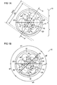
- FIG 1A shows an exemplary embodiment of a Schichtabscheidevorraum according to the proposed principle in supervision.
- the Schichtabschreibevorraum comprises a chamber 10 having a process gas space 11 and a substrate carrier 12.
- the substrate carrier 12 is designed as a circular plate.
- a central axis of the process gas space 11 corresponds to a rotational symmetry axis 27 of the substrate carrier 12.
- a first substrate 13 to be coated and five further substrates 14 to 18 to be coated are arranged on the substrate carrier 12.
- the six substrates 13 to 18 to be coated are arranged on the substrate carrier 12.
- a center of the first substrate 13 lies on a circular line 19 whose center lies in the rotational symmetry axis 27 of the substrate carrier 12.
- the centers of the further substrates 14 to 18 lie on the circle line 19.
- the process gas space 11 is substantially cylindrical.
- a diameter D2 of the substrate carrier 12 is smaller than a diameter D3 of the process gas space 11. Therefore, the chamber 10 has a gap 20 between the substrate carrier 12 and a wall of the process gas space 11.
- the process gas space 11 comprises a first segment 21 and a second segment 22, which is separated from the first segment by a partition wall 23.
- the partition wall 23 extends through the center axis of the process gas space 11 and through the rotational symmetry axis 27 of the substrate carrier 12.
- the partition wall 23 extends from a portion of the wall of the process gas space 11 to an opposite portion of the wall of the process gas space 11.
- a length L of the partition wall 23 is thus the diameter D3 of the process gas space 11.
- the process gas space 11 has a first and a second gas supply 25, 26.
- the first gas supply 25 has an outlet in the first segment 21.
- the second gas supply 26 has an outlet in the second segment 22.
- the gap 20 is provided with a in Figure 1A Not shown vacuum system 24 connected. The gap 20 serves for gas extraction.
- the chamber 10 is opened.
- the substrates 13 to 18 to be coated are arranged on the substrate carrier 12.
- a negative pressure in the process gas space 11 is generated by means of the vacuum system 24.
- gas supply system 28 are first introduced purge gases into the first and the second segment 21, 22 of the process gas chamber 11 via the two gas supply lines 25, 26.
- the substrate carrier 12 is rotated about the rotational symmetry axis 27 in accordance with the in FIG Figure 1A shown arrow turned.
- the partition wall 23 does not touch the substrate carrier 12 and the substrates 13 to 19.
- the first substrate 13, which according to Figure 1A in the first segment 21 is moved into the second segment 22.
- the first gas feed 25 directs a first process gas G1 into the first segment 21.
- the second gas feed 26 directs a second process gas G2 into the second segment 22.
- a first layer is deposited on the substrate 13.
- a second layer is deposited on the substrate 13 by means of the second process gas G2.
- the first substrate 13 is located alternately in the first and in the second segment 21, 22, so that a desired layer sequence is deposited on the first substrate 13. For example, by means of the first process gas G1 a monolayer of atoms of a first component of a compound semiconductor and by means of the second process gas G2 a monolayer of atoms of a second component of the compound semiconductor can be deposited.
- two segments 21, 22 can be achieved with different process conditions by means of the partition wall.
- the partition wall 23 prevents a mixing of the first process gas G1 with the second process gas G2.
- the substrate carrier 12 is formed for receiving additional substrates.
- the additional substrates may be arranged along a further circular line around the rotational symmetry axis 27 of the substrate carrier 12.
- the substrate carrier 12 is designed for receiving substrates such that the substrates are not arranged on circular lines.
- the substrates may be arranged according to the principle of the densest ball packing.
- a single substrate 13 is disposed on the substrate carrier 12.
- the substrate 13 may be located simultaneously in the first and second segments 21, 22.
- the substrate 13 may have a value for a diameter larger than 200 mm.
- the substrate carrier 12 may be formed as a gas cushion, on which the substrate 13 floats.
- the Schichtabschreibevoriques is formed as an atmospheric pressure reactor. In this case, a slight overpressure is present in the chamber 10. The overpressure can assume a value from an interval between 1 mbar and 2 bar.
- a suction device is provided for each of the segments 21, 22.
- FIG. 1B shows a further exemplary embodiment of a Schichtabscheidevorraum according to the proposed principle.
- the Schichtabschreibevoroplasty according to FIG. 1B is a further education of in Figure 1A shown Schichtabscheidevorraum.
- the process gas space 11 ' comprises a second and a third partition wall 30, 31, so that the process gas space 11' comprises a third and a fourth segment 32, 33.
- the four segments 21, 22, 32, 33 have different sizes.
- the partitions 23, 30, 31 is thus the cylindrical process gas space 11 'divided into four parts. In this case, an area of the first segment 21 of the in FIG.
- the chamber 10 includes a third gas supply 34 in the third segment 32 for supplying a third process gas G3 and a fourth gas supply 35 in the fourth segment 33 for supplying a fourth process gas G4.
- the third gas supply 34 acts on the third segment 32 with the third process gas G3. Accordingly, the fourth gas supply G4 pressurizes the fourth segment 33 with the fourth process gas G4.
- the four segments 21, 22, 32, 33 can be charged with different gases.
- the first and third segments 21, 32 can be supplied with purge gases with gases which contain components of the layer as well as the second and fourth segments 22, 33.
- a purge gas may be, for example, nitrogen or argon.
- the substrate carrier 12 moves at a rotation time T.
- ⁇ 1 is an angle of the first segment 21.
- the partition wall 23 is arranged on the two legs of the angle ⁇ 1.
- the first substrate 13 is for a second time period T2 in the second segment 22, for a third time duration T3 in the third segment 30 and for a fourth time duration T4 in the fourth segment 33 according to the following equations:
- T ⁇ 2 ⁇ ⁇ 2 360 ⁇ ° ⁇ T .
- T ⁇ 3 ⁇ ⁇ 3 360 ⁇ ° ⁇ T .
- the exposure times of the first substrate 13 in the individual segments can thus be determined by means of the position of the partitions 23, 30, 31.
- the exposure times for applying the first process gas G1, for the purging after the application of the first process gas G1, for the application of the third process gas G3 and for the purging after the application of the third process gas G3 are individually adjustable. Exposure times T1 to T4 may be, for example, between 0.01 and 10 seconds.
- FIG. 1C shows a further exemplary embodiment of a Schichtabscheidevorraum according to the proposed principle.
- the Schichtabschreibevortechnisch according to Figure 1C is a further education of in Figures 1A and 1B illustrated embodiments.
- the process gas space 11 "according to Figure 1C includes six segments.
- the substrate 13 successively passes through the first segment 21, the second segment 22, the third segment 32, the fourth segment 33, a fifth segment 36 and a sixth segment 37.
- the process gas space 11 '' thus comprises a fourth and a fifth partition wall 38, 39th
- the fourth partition wall 38 is disposed between the fourth segment 33 and the fifth segment 36 and the fifth partition wall 39 is disposed between the fifth segment 36 and the sixth segment 37.
- the chamber comprises a fifth and a sixth gas feed 40, 41 in the fifth and in the sixth segment 36, 37th
- the six exposure times T1 to T6 for the six different process gases G1 to G6 can be set.
- mixing of the first and fifth process gases G1, G5 with the group III component with the third process gas G3 with the group V component of the compound semiconductor is kept low.
- Different carrier gases can be used for the different components.
- different carrier gases can be used for the same components.
- FIG. 1D shows an exemplary embodiment of a Schichtabscheidevorraum in cross section.
- FIG. 1D shows a cross section along an in Figure 1A indicated line AA '.
- the Schichtabschreibevortechnisch according to FIG. 1D is designed as a vertical reactor.
- the Schichtabschreibevortechnik is therefore referred to as a vertical reactor, since the main direction of movement of the process gases G1, G2 in the process gas space 11 is perpendicular to the substrates 13, 16.
- the first and the further substrate 13, 16 lie in recesses of the substrate carrier 12. Thus, a surface of the substrate carrier 12 and a surface of the substrates 13, 16 approximately form a plane.
- the process gas space 11 is arranged, which comprises the first and the second segment 21, 22.
- the first and the second gas supply 25, 26 are arranged opposite the substrate carrier 12.
- the partition wall 23 is arranged between the first and the second segment 21, 22.
- the partition wall 23 has a distance D1 from the substrate carrier 12.
- the chamber 10 has a first heater 42 and a second heater 43.
- the two heaters 42, 43 are arranged below the substrate carrier 12.
- the Schichtabschreibevoriques comprises the vacuum system 24, which is connected to the circumferential gap 20.
- the Schichtabscheidevorraum has a device 44 for moving the substrate support 12 relative to the partition wall 23.
- the device 44 includes a motor 46.
- An axle 45 of the motor 46 is connected to the substrate carrier 12.
- the rotational symmetry axis 27 of the substrate carrier 12 corresponds to a central axis of the axis 45.
- the layer separation device comprises a gas supply system 28, which is connected via supply lines to the first gas feed 25 and the second gas feed 26.
- the substrates 13, 16 are placed on the substrate carrier 12.
- the vacuum system 24 generates a negative pressure below the substrate support 12 and in the process gas space 11.
- the absolute pressure in the process gas space 11 can be a value from an interval between 1 mbar and 1 bar.
- the motor 46 and the axis 47 of the substrate carrier 12 can be set in a rotational movement with the rotation time T.
- the first and second heaters 42, 43 are provided for heating the substrates 13 to 19.
- the substrates 13 to 19 have a temperature suitable for the deposition process.
- the gas supply system 28 provides purge gases for the purge step and the first and second process gases G1, G2 during the deposition process.
- the first process gas G1 comprises a group III precursor and a carrier gas and the second process gas G2 comprises a group V precursor and a carrier gas.
- the coating of the substrates 13, 16 is carried out from above. Therefore, such a Schichtabscheidevoriques is also referred to as a face-up arrangement.
- FIG. 1E shows a further exemplary embodiment of a Schichtabscheidevorplatz in cross-section, a further development of in FIG. 1D shown Schichtabscheidevorraum is.
- Schichtabschreibevortechnik shown is also formed as a vertical reactor.
- the substrates 13, 16 are coated from below.
- the substrate carrier 12 has recesses on which the substrates 13, 16 lie, so that the substrates 13, 16 can be coated from below through the recesses.
- the substrates 13 to 19 are thus inserted with the side to be coated down into the substrate carrier 12. Therefore, such a Schichtabscheidevortechnik also referred to as a face-down arrangement.
- the process gas space 11 is thus arranged below the substrate carrier 12.
- the other components of the Schichtabschreibevorettivorraumraum correspond to those in FIG.
- FIG. 1F shows a further exemplary embodiment of a Schichtabscheidevorraum in cross section.
- Schichtabschreibevoroplasty shown is a development of the Schichtabscheidevortechnik according to FIG. 1D
- Schichtabschreibevorraum shown is realized as a horizontal reactor.
- the main movement of the process gases G1, G2 in the horizontal direction ie substantially parallel to the surface of the substrates 13, 16.
- the horizontal flow is by the arrangement of the gas outlets 25, 26 in close proximity to the surface of the substrate support 12 and achieved by the extraction of the process gas space 11 at the edge of the chamber 10.
- the Schichtabschreibevorraumraumraum is realized as a face-up arrangement.
- FIG. 2 shows a further exemplary embodiment of a Schichtabscheidevorraum according to the proposed principle.
- FIG. 2 is a further education of in FIG. 1B shown embodiment shown.
- the first gas supply 25 is arranged on the wall of the process gas space 11 in the first segment 21.
- the second, the third and the fourth gas supply 26, 34, 35 on the wall of the process gas space 11 '''in the second, third and fourth segments 22, 32, 34 are arranged.
- the process gases G1 to G4 starting from the wall of the process gas space 11 '''move laterally over the substrates 13 to 19 to the center of the process gas space 11''', where they sucked by means of the opening 50, which leads to the vacuum system 24 become.
- FIG. 2 is thus the flow direction of the process gases G1 to G4 compared to the embodiment in FIG. 1B vice versa.
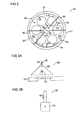
- FIG. 3A shows an exemplary embodiment of a gas supply.
- the gas supply 25 comprises a gas distribution device 60 with an inlet 61 and a plurality of outlets 62.
- the outlets 62 are arranged opposite to the substrate carrier 12.
- a distance between the gas distribution device 60 and the substrate carrier 12 is small. The distance is for example 1 cm.
- the outlets 62 are arranged opposite the region of the substrate carrier 12 in which the various substrates 13 to 19 are located in succession.
- a high homogeneity of the gas concentration over the substrate 13 and thus a high homogeneity of the layer deposition is achieved by means of the gas distribution device 60.
- FIG. 3B shows an exemplary alternative embodiment of a gas supply.
- the gas supply 25 includes a Pyrolysis device 70.
- the pyrolysis device 70 has a heating source. With the pyrolysis device 70, the process gas is decomposed pyrolytically.
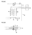
- FIG. 3C shows an exemplary embodiment of a segment with a device 80 for generating a plasma.
- the device 80 has a first and a second electrode 81, 82.
- the two electrodes 81 and 82 are connected to an AC voltage generator 83, which is arranged outside the chamber 10.
- the segment is designed for plasma epitaxy.
- the plasma can be generated near the substrates 13 to 18, in particular at a distance of 0.5 to 2 cm, or away from the substrates 13 to 18 in the process gas space 11.
- a reaction of the process gas G1 by means of the plasma can be carried out before it hits the substrate.
- the plasma may be generated in one of the gas feeds 25, 26, 34, 35, 36, 37 or in an antechamber preceding the chamber 10.
- Figure 3D shows an exemplary embodiment of a substrate carrier.
- the substrate carrier 12 comprises a rotating device 90.
- the rotating device 90 has a turntable 91 for receiving the substrate 13.
- the rotary device 90 comprises a motor 92 whose axis is connected to a rotation axis of the turntable 91.
- the substrate 13 can be rotated about the axis of the turntable 91 and thus around the center of the substrate 13 during the deposition process.
- a uniformity of the layer deposition on the substrate 13 is thus increased.
- the turntable 91 comprises receptacles for a plurality of substrates.
- the capacity of the Schichtabscheidevorraum can be further increased.
- the drive is done without a motor.
- the drive can be generated by means of a flow in the gas cushion on which the substrate or substrates 13 or on which the substrate carrier 12 floats.
Landscapes
- Chemical & Material Sciences (AREA)
- General Chemical & Material Sciences (AREA)
- Chemical Kinetics & Catalysis (AREA)
- Engineering & Computer Science (AREA)
- Materials Engineering (AREA)
- Mechanical Engineering (AREA)
- Metallurgy (AREA)
- Organic Chemistry (AREA)
- Inorganic Chemistry (AREA)
- Chemical Vapour Deposition (AREA)
- Physical Vapour Deposition (AREA)
Abstract
Description
- Diese Patentanmeldung beansprucht die Priorität der deutschen Patentanmeldungen
DE 10 2007 046 606.6 undDE 10 2008 010 041.2 , deren Offenbarungsgehalte hiermit durch Rückbezug aufgenommen werden. - Die vorliegende Erfindung betrifft eine Schichtabscheidevorrichtung und ein Verfahren zum Betrieb einer Schichtabscheidevorrichtung.
- Bei der Abscheidung einer Schicht in einer Schichtabscheidevorrichtung werden üblicherweise die Prozessgase, die zur Herstellung der Schicht benötigt werden, gleichzeitig stationär über ein zu beschichtendes Substrat geleitet. Dies kann zu Vorreaktionen in der Gasphase führen. Durch die Vorreaktionen werden Partikel in einem Prozessgasraum erzeugt, die sich auf dem Substrat anordnen können.
- Dokument
US 6,576,062 B2 befasst sich mit einer Schichtabscheidevorrichtung mit einer ersten und einer zweiten Gaszuführung. - Aufgabe der Erfindung ist es, eine Schichtabscheidevorrichtung und ein Verfahren zum Betrieb einer Schichtabscheidevorrichtung bereitzustellen, welche eine Vorreaktion von Prozessgasen verringern.
- Diese Aufgabe wird mit dem Gegenstand mit den Merkmalen des Anspruchs 1 sowie mit dem Verfahren gemäß Patentanspruch 15 gelöst. Weiterbildungen und Ausgestaltungen sind jeweils Gegenstand der abhängigen Ansprüche.
- In einer Ausführungsform weist eine Schichtabscheidevorrichtung eine Kammer auf. Die Kammer umfasst einen Substratträger zur Aufnahme von einem zu beschichtenden Substrat und einen Prozessgasraum. Der Prozessgasraum weist ein erstes und ein zweites Segment sowie eine Trennwand auf. Die Trennwand trennt das erste Segment und das zweite Segment voneinander. Weiter umfasst die Schichtabscheidevorrichtung eine Vorrichtung zum Bewegen des Substrates relativ zu der Trennwand.
- Mit Vorteil ist die Trennwand zwischen dem ersten und dem zweiten Segment angeordnet, so dass erste Prozessbedingungen im ersten Segment unabhängig von zweiten Prozessbedingungen im zweiten Segment eingestellt werden können. Somit werden Vorreaktionen von Prozessgasen verringert. Unter einem Gas wird hierbei auch ein Plasma verstanden. In einer Ausführungsform kann mittels der Vorrichtung zum Bewegen des Substrates der Substratträger relativ zu der Trennwand bewegt werden. Der Substratträger kann derart bewegt werden, dass das zu beschichtende Substrat vom ersten Segment in das zweite Segment bewegt werden kann, so dass das Substrat abwechselnd und nacheinander mittels der ersten und der zweiten Prozessbedingungen beschichtet werden kann.
- In einer Ausführungsform umfasst die Kammer eine erste Gaszuführung in das erste Segment und eine zweite Gaszuführung in das zweite Segment. Mit Vorteil können mittels der ersten und der zweiten Gaszuführung ein erstes Prozessgas in das erste Segment und ein zweites Prozessgas in das zweite Segment eingeleitet werden. Das erste und das zweite Prozessgas sind bevorzugt unterschiedlich. Durch die Trennwand wird das erste Segment von dem zweiten Segment derart abgetrennt, dass vorteilhafterweise sich das erste Prozessgas nicht mit dem zweiten Prozessgas mischt, so dass Vorreaktionen der beiden Prozessgase vermieden werden.
- In einer Ausführungsform ist die Schichtabscheidevorrichtung zur chemischen Abscheidung aus der Gasphase, englisch chemical vapor deposition, abgekürzt CVD, ausgebildet. Bevorzugt ist die Schichtabscheidevorrichtung als Epitaxieschichtabscheidevorrichtung realisiert. Die Schichtabscheidevorrichtung kann für ein Atomlagenepitaxieverfahren, englisch atomic layer epitaxy, realisiert sein. Die Schichtabscheidevorrichtung kann somit zum Abscheiden von Verbindungshalbleitern verwendet werden. Dabei kann beispielsweise eine Atomlage einer ersten Komponente des Verbindungshalbleiters im ersten Segment und eine Atomlage einer zweiten Komponente des Verbindungshalbleiters im zweiten Segment abgeschieden werden. Bevorzugt befindet sich das Substrat mehrfach abwechselnd im ersten und im zweiten Segment, so dass eine eine Vielzahl von Atomlagen aufweisende Schicht abgeschieden werden kann.
- In einer Ausführungsform ist der Substratträger als kreisförmiger Teller ausgebildet. Der kreisförmige Teller weist eine Rotationssymmetrieachse auf. Der Substratträger und der Prozessgasraum sind gegeneinander rotierbar angeordnet. Dabei kann eine Rotationsachse der Relativbewegung die Rotationssymmetrieachse des Tellers sein. Bevorzugt ist das Substrat außerhalb der Rotationsymmetrieachse des Tellers und damit außerhalb der Rotationsachse angeordnet.
- In einer Ausführungsform ist der Substratträger zur Aufnahme von einer Mehrzahl von zu beschichtenden Substraten ausgelegt.
- In einer Ausführungsform ist der Substratträger als Gaskissen aus dem Prozessgas oder einem Trägergas ausgebildet, auf dem das zumindest eine Substrat schwebt. Das Gaskissen kann derartig ausgebildet sein, dass das zumindest eine Substrat in eine Rotationsbewegung versetzt wird.
- In einer Ausführungsform ist der Prozessgasraum im Wesentlichen zylinderförmig. Bevorzugt verläuft die Trennwand durch eine Mittelachse des Zylinders. Die Mittelachse kann die Rotationsachse sein. Die Trennwand kann im Wesentlichen als Rechteck ausgebildet sein. Alternativ umfasst die Trennwand ein oder mehrere Rechtecke. Die Trennwand kann als mechanische Trennwand ausgebildet sein. Die Trennwand kann als Festkörper realisiert sein. Die Trennwand kann ein gasundurchlässiges Material enthalten. Ein Material der Trennwand kann wärmeresistent sein. Das Material kann bis zu einer Temperatur von 1000 Grad Celsius temperaturstabil sein. Alternativ kann das Material bis zu einer Temperatur von 2000 Grad Celsius temperaturstabil sein. Das Material kann porös sein. Das Material kann Keramik, Edelstahl oder Molybdän enthalten.
- In einer Ausführungsform teilt die Trennwand den zylinderförmigen Prozessgasraum derart, dass das erste Segment und das zweite Segment gleich groß sind. In einer alternativen Ausführungsform sind das erste und das zweite Segment unterschiedlich groß.
- In einer Weiterbildung umfasst die Vorrichtung zum Bewegen des Substratträgers relativ zu der Trennwand einen Motor. Das Substrat kann in einem ersten Betriebszustand im ersten Segment und in einem zweiten Betriebszustand im zweiten Segment angeordnet sein.
- Bevorzugt ist der Substratträger beweglich gegenüber der Kammer angeordnet. Damit ist der Substratträger beweglich gegenüber dem Prozessgasraum. In dieser Ausführungsform sind die Trennwand sowie die erste und die zweite Gaszuführung fest mit der Kammer verbunden.
- In einer Ausführungsform weist die Trennwand einen Abstand zu dem Substratträger auf. Der Abstand kann einen Wert kleiner 20 mm aufweisen. Alternativ kann der Abstand einen Wert kleiner 5 mm aufweisen. Bevorzugt kann der Abstand einen Wert zwischen 1 mm und 0,1 mm aufweisen. Mit Vorteil ist somit ausschließlich ein kleiner Spalt zwischen dem Substratträger und der Trennwand vorhanden, durch den allenfalls ein geringer Gasaustausch zwischen dem ersten und dem zweiten Segment möglich ist.
- In einer Ausführungsform sind eine Oberfläche des Substratträgers und eine Oberfläche des Substrats in einer gemeinsamen Ebene angeordnet. Mit Vorteil bildet somit die Trennwand einen Spalt mit einem konstanten Abstand sowohl gegenüber dem Substratträger als auch gegenüber dem Substrat. Aufgrund der Rotation des Substratträgers durchläuft das Substrat nacheinander das erste und das zweite Segment, wobei beim Passieren der Trennwand die Gasphase über dem Substrat bis auf einen kleinen Rest abgeschert wird.
- In einer Ausführungsform umfasst die Schichtabscheidevorrichtung eine Drehvorrichtung zum Rotieren des Substrats gegenüber dem Substratträger. Mit Vorteil wird somit das Substrat, während es sich beispielsweise im ersten Segment befindet, gedreht, sodass eine Gleichmäßigkeit der Schichtabscheidung erhöht ist.
- In einer Ausführungsform umfasst ein Verfahren zum Betrieb einer Schichtabscheidevorrichtung ein Anordnen von mindestens einem zu beschichtenden Substrat auf einem Substratträger. Erste Prozessbedingungen werden in einem ersten Segment eines Prozessgasraums eingestellt. Weiter werden zweite Prozessbedingungen in einem zweiten Segment des Prozessgasraums eingestellt. Dabei trennt eine Trennwand das erste Segment von dem zweiten Segment. Das Substrat wird relativ zu der Trennwand bewegt.
- Mit Vorteil können die ersten und die zweiten Prozessbedingungen im ersten und im zweiten Segment unterschiedlich und getrennt voneinander eingestellt werden, so dass Vorreaktionen verringert werden. Das Substrat kann dadurch bewegt werden, dass der Substratträger bewegt wird.
- In einer Ausführungsform wird zum Einstellen der ersten Prozessbedingungen ein erstes Prozessgas in das erste Segment eingeleitet. Ein zweites Prozessgas wird in das zweite Segment zum Einstellen der zweiten Prozessbedingungen eingeleitet. Das erste Prozessgas ist bevorzugt verschieden von dem zweiten Prozessgas. Durch die Trennwand wird vorteilhafterweise ein Vermischen des ersten Prozessgases im ersten Segment mit dem zweiten Prozessgas im zweiten Segment verringert, sodass Vorreaktionen des ersten Prozessgases mit dem zweiten Prozessgas reduziert sind.
- In einer Ausführungsform wird eine Epitaxieschicht auf dem Substrat abgeschieden. Die Epitaxieschicht kann als Verbindungshalbleiter ausgebildet sein. Dabei kann das erste Prozessgas eine erste Komponente des Verbindungshalbleiters und das zweite Prozessgas eine zweite Komponente des Verbindungshalbleiters aufweisen.
- Das Substrat wird bevorzugt mehrfach alternierend dem ersten und dem zweiten Segment des Prozessgasraums ausgesetzt. Mit Vorteil kann somit atomlagenweise eine Epitaxieschicht abgeschieden werden. Eine erste Expositionszeit des Substrats im ersten Segment und eine zweite Expositionszeit des Substrats im zweiten Segment können vorteilhafterweise durch Festlegung einer Rotationsdauer eines Substratträgers, welcher zur Aufnahme des Substrats ausgelegt ist, eingestellt werden. Somit kann mit Vorteil erzielt werden, dass das Substrat dem ersten Prozessgas und dem zweiten Prozessgas jeweils nur für eine kurze Dauer ausgesetzt sind.
- Die Rotationsdauer kann kleiner 30 Sekunden sein. Weitergehend kann die Rotationsdauer kleiner 0,1 Sekunden sein. Bevorzugt kann die Rotationsdauer kleiner 10 Sekunden sein.
- In einer Ausführungsform umfasst das erste Prozessgas ein erstes Trägergas und das zweite Prozessgas ein zweites Trägergas. Das erste Trägergas kann verschieden von dem zweiten Trägergas sein, sodass ein für die jeweilige Komponente des Verbindungshalbleiters geeignetes Trägergas ausgewählt werden kann.
- Der Verbindungshalbleiter kann auf einem III-V-Verbindungshalbleiter oder auf einem II-VI-Verbindungshalbleiter basieren. Der III-V-Verbindungshalbleiter kann auf einem Nitrid-Verbindungshalbleiter, einem Phosphid-Verbindungshalbleiter, einem Antimonid-Verbindungshalbleiter, einem Arsenid-Verbindungshalbleiter oder aus einer Legierung daraus basieren.
- "Auf Nitrid-Verbindungshalbleitern basierend" bedeutet im vorliegenden Zusammenhang, dass die aktive Epitaxie-Schichtenfolge oder zumindest eine Schicht davon ein Nitrid-III-Verbindungshalbleitermaterial, vorzugsweise AlnGamIn1-n-mN umfasst, wobei 0 ≤ n ≤ 1, 0 ≤ m ≤ 1 und n+m ≤ 1. Dabei muss dieses Material nicht zwingend eine mathematisch exakte Zusammensetzung nach obiger Formel aufweisen. Vielmehr kann es einen oder mehrere Dotierstoffe sowie zusätzliche Bestandteile aufweisen, die die charakteristischen physikalischen Eigenschaften des AlnGamIn1-n-mN-Materials im Wesentlichen nicht ändern. Der Einfachheit halber beinhaltet obige Formel jedoch nur die wesentlichen Bestandteile des Kristallgitters Al, Ga, In, N, auch wenn diese teilweise durch geringe Mengen weiterer Stoffe ersetzt sein können.
- "Auf Phosphid-Verbindungshalbleitern basierend" bedeutet in diesem Zusammenhang, dass der Halbleiterkörper, insbesondere der aktive Bereich vorzugsweise AlnGamIn1-n-mP umfasst, wobei 0 ≤ n ≤ 1, 0 ≤ m ≤ 1 und n+m ≤ 1 ist, vorzugsweise mit n ≠ 0 und/oder m ≠ 0. Dabei muss dieses Material nicht zwingend eine mathematisch exakte Zusammensetzung nach obiger Formel aufweisen. Vielmehr kann es ein oder mehrere Dotierstoffe sowie zusätzliche Bestandteile aufweisen, die die physikalischen Eigenschaften des Materials im Wesentlichen nicht ändern. Der Einfachheit halber beinhaltet obige Formel jedoch nur die wesentlichen Bestandteile des Kristallgitters Al, Ga, In, P, auch wenn diese teilweise durch geringe Mengen weiterer Stoffe ersetzt sein können.
- "Auf Antimonid-Verbindungshalbleitern basierend" bedeutet in diesem Zusammenhang, dass der Halbleiterkörper, insbesondere der aktive Bereich vorzugsweise AlnInmGa1-n-mSb umfasst, wobei 0 ≤ n ≤ 1, 0 ≤ m ≤ 1 und n+m ≤ 1 ist. Dabei muss dieses Material nicht zwingend eine mathematisch exakte Zusammensetzung nach obiger Formel aufweisen. Vielmehr kann es ein oder mehrere Dotierstoffe sowie zusätzliche Bestandteile aufweisen, die die physikalischen Eigenschaften des Materials im Wesentlichen nicht ändern. Der Einfachheit halber beinhaltet obige Formel jedoch nur die wesentlichen Bestandteile des Kristallgitters Al, In, Ga, Sb, auch wenn diese teilweise durch geringe Mengen weiterer Stoffe ersetzt sein können.
- "Auf Arsenid-Verbindungshalbleitern basierend" bedeutet in diesem Zusammenhang, dass der Halbleiterkörper, insbesondere der aktive Bereich vorzugsweise AlnInmGa1-n-mAs umfasst, wobei 0 ≤ n ≤ 1, 0 ≤ m ≤ 1 und n+m ≤ 1 ist. Dabei muss dieses Material nicht zwingend eine mathematisch exakte Zusammensetzung nach obiger Formel aufweisen. Vielmehr kann es ein oder mehrere Dotierstoffe sowie zusätzliche Bestandteile aufweisen, die die physikalischen Eigenschaften des Materials im Wesentlichen nicht ändern. Der Einfachheit halber beinhaltet obige Formel jedoch nur die wesentlichen Bestandteile des Kristallgitters Al, In, Ga, As, auch wenn diese teilweise durch geringe Mengen weiterer Stoffe ersetzt sein können.
- "Auf II-VI-Verbindungshalbleitern basierend" bedeutet in diesem Zusammenhang, dass der Halbleiterkörper, insbesondere der aktive Bereich, eine Verbindung mindestens einer Komponente aus der zweiten Hauptgruppe des Periodensystems, insbesondere Beryllium, Magnesium, Zink, Cadmium und Quecksilber, mit mindestens einer Komponente aus der sechsten Hauptgruppe, insbesondere Sauerstoff, Schwefel, Selen und Tellur, aufweist. Der II-VI-Verbindungshalbleiter kann vorzugsweise ZnnCd1-nSmSe1-m umfassen, wobei 0 ≤ n ≤ 1 und 0 ≤ m ≤ 1 ist. Dabei muss dieses Material nicht zwingend eine mathematisch exakte Zusammensetzung aufweisen. Vielmehr kann es ein oder mehrere Dotierstoffe sowie zusätzliche Bestandteile aufweisen, die die physikalischen Eigenschaften des Materials im wesentlichen nicht ändern. Der Einfachheit halber beinhaltet obige Formel jedoch nur die wesentlichen Bestandteile des Kristallgitters Zn, Cd, S, Se, auch wenn diese teilweise durch geringe Mengen weiterer Stoffe ersetzt sein können. Die II-VI Verbindungshalbleiter können beispielsweise Sulfide und/oder Selenide umfassen.
- Der Verbindungshalbleiter kann zur Herstellung einer Leuchtdiode, insbesondere eines Dünnfilm-Leuchtdioden-Chips, eines Lasers, einer Solarzelle oder eines Detektors abgeschieden werden.
- Die Erfindung wird nachfolgend an mehreren Ausführungsbeispielen anhand der Figuren näher erläutert. Funktionsbeziehungsweise wirkungsgleiche Komponenten und Bauteile tragen gleiche Bezugszeichen. Insoweit sich Komponenten oder Bauteile in ihrer Funktion entsprechen, wird deren Beschreibung nicht in jeder der folgenden Figuren wiederholt.
- Es zeigen:
- Figuren 1A bis 1F
- jeweils eine beispielhafte Ausführungsform einer Schichtabscheidevorrichtung nach dem vorgeschlagenen Prinzip,
- Figur 2
- eine alternative beispielhafte Ausführungsform einer Schichtabscheidevorrichtung nach dem vorgeschlagenen Prinzip und
- Figuren 3A bis 3D
- beispielhafte Komponenten einer Schichtabscheidevorrichtung nach dem vorgeschlagenen Prinzip.
-
Figur 1A zeigt eine beispielhafte Ausführungsform einer Schichtabscheidevorrichtung nach dem vorgeschlagenen Prinzip in Aufsicht. Die Schichtabscheidevorrichtung umfasst eine Kammer 10 mit einem Prozessgasraum 11 und einem Substratträger 12. Der Substratträger 12 ist als kreisförmiger Teller ausgeführt. Eine Mittelachse des Prozessgasraums 11 entspricht einer Rotationssymmetrieachse 27 des Substratträgers 12. Auf dem Substratträger 12 sind ein erstes zu beschichtendes Substrat 13 sowie fünf weitere zu beschichtende Substrate 14 bis 18 angeordnet. Die sechs zu beschichtenden Substrate 13 bis 18 sind auf dem Substratträger 12 angeordnet. Ein Mittelpunkt des ersten Substrats 13 liegt auf einer Kreislinie 19, deren Mittelpunkt in der Rotationssymmetrieachse 27 des Substratträgers 12 liegt. Ebenfalls liegen die Mittelpunkte der weiteren Substrate 14 bis 18 auf der Kreislinie 19. - Der Prozessgasraum 11 ist im Wesentlichen zylinderförmig ausgebildet. Ein Durchmesser D2 des Substratträgers 12 ist kleiner als ein Durchmesser D3 des Prozessgasraums 11. Daher weist die Kammer 10 einen Spalt 20 zwischen dem Substratträger 12 und einer Wand des Prozessgasraums 11 auf. Der Prozessgasraum 11 umfasst ein erstes Segment 21 und ein zweites Segment 22, das vom ersten Segment durch eine Trennwand 23 getrennt ist. Die Trennwand 23 verläuft durch die Mittelachse des Prozessgasraums 11 und durch die Rotationssymmetrieachse 27 des Substratträgers 12. Die Trennwand 23 erstreckt sich von einem Abschnitt der Wand des Prozessgasraums 11 zu einem gegenüberliegenden Abschnitt der Wand des Prozessgasraums 11. Eine Länge L der Trennwand 23 ist somit der Durchmesser D3 des Prozessgasraums 11. Weiter weist der Prozessgasraum 11 eine erste und eine zweite Gaszuführung 25, 26 auf. Die erste Gaszuführung 25 hat einen Auslass in das erste Segment 21. Entsprechend hat die zweite Gaszuführung 26 einen Auslass in das zweite Segment 22. Der Spalt 20 ist mit einem in
Figur 1A nicht gezeigten Vakuumsystem 24 verbunden. Der Spalt 20 dient zur Gasabsaugung. - Zum Abscheiden einer Schicht wird zunächst die Kammer 10 geöffnet. Die zu beschichtenden Substrate 13 bis 18 werden auf dem Substratträger 12 angeordnet. Nach dem Schließen der Kammer 10 wird mittels des Vakuumsystems 24 ein Unterdruck im Prozessgasraum 11 erzeugt. Mittels eines in
Figur 1A nicht gezeigten Gasversorgungssystems 28 werden über die beiden Gaszuführungen 25, 26 zuerst Spülgase in das erste und das zweite Segment 21, 22 des Prozessgasraums 11 eingeleitet. Anschließend wird der Substratträger 12 um die Rotationssymmetrieachse 27 entsprechend dem inFigur 1A gezeigten Pfeil gedreht. Dabei berührt die Trennwand 23 den Substratträger 12 sowie die Substrate 13 bis 19 nicht. Das erste Substrat 13, das sich gemäßFigur 1A im ersten Segment 21 befindet, wird in das zweite Segment 22 bewegt. Weiter leitet die erste Gaszuführung 25 ein erstes Prozessgas G1 in das erste Segment 21. Entsprechend leitet die zweite Gaszuführung 26 ein zweites Prozessgas G2 in das zweite Segment 22. Mittels des ersten Prozessgases G1 wird eine erste Schicht auf dem Substrat 13 abgeschieden. Nach dem Drehen des ersten Substrats 13 von dem ersten Segment 21 in das zweite Segment 22 wird mittels des zweiten Prozessgases G2 eine zweite Schicht auf dem Substrat 13 abgeschieden. Das erste Substrat 13 befindet sich alternierend im ersten und im zweiten Segment 21, 22, sodass eine gewünschte Schichtenfolge auf dem ersten Substrat 13 abgeschieden wird. Beispielsweise kann mittels des ersten Prozessgases G1 eine Monolage von Atomen einer ersten Komponente eines Verbindungshalbleiters und mittels des zweiten Prozessgases G2 eine Monolage von Atomen einer zweiten Komponente des Verbindungshalbleiters abgeschieden werden. - Mit Vorteil können mittels der Trennwand zwei Segmente 21, 22 mit unterschiedlichen Prozessbedingungen erzielt werden. Damit ist eine hohe Flexibilität bei der Abscheidung von Schichten möglich. Mit Vorteil verhindert die Trennwand 23 eine Vermischung des ersten Prozessgases G1 mit dem zweiten Prozessgas G2.
- In einer alternativen, nicht gezeigten Ausführungsform ist der Substratträger 12 zur Aufnahme von zusätzlichen Substraten ausgebildet. Die zusätzlichen Substrate können entlang einer weiteren Kreislinie um die Rotationssymmetrieachse 27 des Substratsträgers 12 angeordnet sein. Somit ist die Kapazität der Schichtabscheidevorrichtung erhöht.
- In einer alternativen, nicht gezeigten Ausführungsform ist der Substratträger 12 zur Aufnahme von Substraten derart ausgebildet, dass die Substrate nicht auf Kreislinien angeordnet sind. Beispielsweise können die Substrate gemäß dem Prinzip der dichtesten Kugelpackung angeordnet sind.
- In einer alternativen, nicht gezeigten Ausführungsform ist ein einzelnes Substrat 13 auf dem Substratträger 12 angeordnet. Das Substrat 13 kann sich gleichzeitig im ersten und im zweiten Segment 21, 22 befinden. Das Substrat 13 kann einen Wert für einen Durchmesser aufweisen, der größer 200 mm ist. In einer Ausführungsform kann der Substratträger 12 als Gaskissen ausgebildet sein, auf dem das Substrat 13 schwebt.
- In einer alternativen, nicht gezeigten Ausführungsform ist die Schichtabscheidevorrichtung als Atmosphärendruck-Reaktor ausgebildet. Dabei ist in der Kammer 10 ein leichter Überdruck vorhanden. Der Überdruck kann einen Wert aus einem Intervall zwischen 1 mbar und 2 bar annehmen.
- In einer alternativen, nicht gezeigten Ausführungsform ist für die Segmente 21, 22 jeweils eine Absaugeinrichtung vorhanden.
-
Figur 1B zeigt eine weitere beispielhafte Ausführungsform einer Schichtabscheidevorrichtung nach dem vorgeschlagenen Prinzip. Die Schichtabscheidevorrichtung gemäßFigur 1B ist eine Weiterbildung der inFigur 1A dargestellten Schichtabscheidevorrichtung. GemäßFigur 1B umfasst der Prozessgasraum 11' eine zweite und eine dritte Trennwand 30, 31, sodass der Prozessgasraum 11' ein drittes und ein viertes Segment 32, 33 umfasst. Die vier Segmente 21, 22, 32, 33 sind unterschiedlich groß. Mittels der Trennwände 23, 30, 31 wird somit der zylinderförmige Prozessgasraum 11' in vier Teile geteilt. Dabei ist eine Fläche des ersten Segments 21 des inFigur 1B gezeigten Querschnitts proportional zu einem ersten Winkel ϕ1, eine Fläche des zweiten Segments proportional zu einem zweiten Winkel ϕ2, eine Fläche des dritten Segments 32 proportional zu einem dritten Winkel ϕ3 und eine Fläche des vierten Segments 33 proportional zu einem vierten Winkel ϕ4. Darüber hinaus umfasst die Kammer 10 eine dritte Gaszuführung 34 in das dritte Segment 32 zur Zuleitung eines dritten Prozessgases G3 und eine vierte Gaszuführung 35 in das vierte Segment 33 zur Zuleitung eines vierten Prozessgases G4. - Die dritte Gaszuführung 34 beaufschlagt das dritte Segment 32 mit dem dritten Prozessgas G3. Entsprechend beaufschlagt die vierte Gaszuführung G4 das vierte Segment 33 mit dem vierten Prozessgas G4. Zum Abscheiden einer Schicht können somit die vier Segmente 21, 22, 32, 33 mit unterschiedlichen Gasen beaufschlagt werden. Beispielsweise können das erste und das dritte Segment 21, 32 mit Gasen, die Komponenten der Schicht enthalten, sowie das zweite und das vierte Segment 22, 33 mit Spülgasen beaufschlagt werden. Ein Spülgas kann beispielsweise Stickstoff oder Argon sein. Der Substratträger 12 bewegt sich mit einer Rotationsdauer T. Somit befindet sich das erste Substrat 13 während einer ersten Dauer T1, die als Expositionszeit bezeichnet werden kann, gemäß folgender Gleichung im ersten Segment 21:

wobei ϕ1 ein Winkel des ersten Segments 21 ist. Die Trennwand 23 ist auf den beiden Schenkeln des Winkels ϕ1 angeordnet. Entsprechend befindet sich das erste Substrat 13 für eine zweite Zeitdauer T2 im zweiten Segment 22, für eine dritte Zeitdauer T3 im dritten Segment 30 und für eine vierte Zeitdauer T4 im vierten Segment 33 gemäß folgenden Gleichungen:
- Mit Vorteil wird eine Vermischung des ersten Prozessgases G1, das sich im ersten Segment 21 befindet, mit dem dritten Prozessgas G3, das sich im dritten Segment 32 befindet, weiter verringert. Mit Vorteil können somit mittels der Lage der Trennwände 23, 30, 31 die Expositionszeiten des ersten Substrats 13 in den einzelnen Segmenten festgelegt werden. Somit sind die Expositionszeiten für das Beaufschlagen mit dem ersten Prozessgas G1, für das Spülen nach dem Beaufschlagen mit dem ersten Prozessgas G1, für das Beaufschlagen mit dem dritten Prozessgas G3 und für das Spülen nach dem Beaufschlagen mit dem dritten Prozessgas G3 einzeln einstellbar. Die Expositionszeiten T1 bis T4 können beispielsweise zwischen 0,01 und 10 Sekunden sein.
-
Figur 1C zeigt eine weitere beispielhafte Ausführungsform einer Schichtabscheidevorrichtung nach dem vorgeschlagenen Prinzip. Die Schichtabscheidevorrichtung gemäßFigur 1C ist eine Weiterbildung der inFiguren 1A und 1B dargestellten Ausführungsformen. Der Prozessgasraum 11'' gemäßFigur 1C umfasst sechs Segmente. Das Substrat 13 durchläuft nacheinander das erste Segment 21, das zweite Segment 22, das dritte Segment 32, das vierte Segment 33, ein fünftes Segment 36 und ein sechstes Segment 37. Der Prozessgasraum 11'' umfasst somit eine vierte und eine fünfte Trennwand 38, 39. - Die vierte Trennwand 38 ist zwischen dem vierten Segment 33 und dem fünften Segment 36 und die fünfte Trennwand 39 ist zwischen dem fünften Segment 36 und den sechsten Segment 37 angeordnet. Darüber hinaus umfasst die Kammer eine fünfte und eine sechste Gaszuführung 40, 41 in das fünfte beziehungsweise in das sechste Segment 36, 37.
- Das Substrat 13 wird somit nacheinander mit sechs verschiedenen Prozessgasen G1 bis G6 in folgender Reihenfolge beaufschlagt:
- G1: Gruppe-III-Komponente des Verbindungshalbleiters mit wasserstoffträgergas,
- G2: Stickstoffträgergas,
- G3: Gruppe-V-Komponente des Verbindungshalbleiters mit Wasserstoffträgergas,
- G4: Wasserstoffträgergas,
- G5: Gruppe-III-Komponente des Verbindungshalbleiters mit Stickstoffträgergas,
- G6: Dotierstoff mit Wasserstoffträgergas.
- Entsprechend den sechs Winkeln ϕ1 bis ϕ6 der sechs Segmente 21, 22, 32, 33, 36, 37 können die sechs Expositionszeiten T1 bis T6 für die sechs verschiedenen Prozessgase G1 bis G6 eingestellt werden.
- Mit Vorteil wird eine Vermischung des ersten und des fünften Prozessgases G1, G5 mit der Gruppe-III-Komponente mit dem dritten Prozessgas G3 mit der Gruppe-V-Komponente des Verbindungshalbleiters gering gehalten. Für die verschiedenen Komponenten können unterschiedliche Trägergase verwendet werden. Ebenfalls können für dieselben Komponenten unterschiedliche Trägergase eingesetzt werden.
-
Figur 1D zeigt eine beispielhafte Ausführungsform einer Schichtabscheidevorrichtung im Querschnitt.Figur 1D zeigt einen Querschnitt entlang einer inFigur 1A angegebenen Linie AA'. Die Schichtabscheidevorrichtung gemäßFigur 1D ist als vertikaler Reaktor ausgebildet. Die Schichtabscheidevorrichtung wird daher als vertikaler Reaktor bezeichnet, da die Hauptrichtung der Bewegung der Prozessgase G1, G2 im Prozessgasraum 11 senkrecht zu den Substraten 13, 16 erfolgt. - Das erste und das weitere Substrat 13, 16 liegen in Vertiefungen des Substratträgers 12. Somit bilden eine Oberfläche des Substratträgers 12 und eine Oberfläche der Substrate 13, 16 näherungsweise eine Ebene. Oberhalb des Substratträgers 12 ist der Prozessgasraum 11 angeordnet, der das erste und das zweite Segment 21, 22 umfasst. Die erste und die zweite Gaszuführung 25, 26 sind gegenüber dem Substratträger 12 angeordnet. Die Trennwand 23 ist zwischen dem ersten und dem zweiten Segment 21, 22 angeordnet. Die Trennwand 23 hat einen Abstand D1 zu dem Substratträger 12. Weiter weist die Kammer 10 einen ersten Heizer 42 und einen zweiten Heizer 43 auf. Die beiden Heizer 42, 43 sind unterhalb des Substratträgers 12 angeordnet. Die Schichtabscheidevorrichtung umfasst das Vakuumsystem 24, das mit dem umlaufenden Spalt 20 verbunden ist. Weiter weist die Schichtabscheidevorrichtung eine Vorrichtung 44 zum Bewegen des Substratträgers 12 relativ zu der Trennwand 23 auf. Die Vorrichtung 44 umfasst einen Motor 46. Eine Achse 45 des Motors 46 ist mit dem Substratträger 12 verbunden. Dabei entspricht die Rotationssymmetrieachse 27 des Substratträgers 12 einer Mittelachse der Achse 45. Ferner umfasst die Schichtabscheidevorrichtung ein Gasversorgungssystem 28, das über Zuleitungen mit der ersten Gaszuführung 25 und der zweiten Gaszuführung 26 verbunden ist.
- Die Substrate 13, 16 werden auf den Substratträger 12 aufgelegt. Das Vakuumsystem 24 erzeugt einen Unterdruck unterhalb des Substratträgers 12 und im Prozessgasraum 11. Der Absolutdruck im Prozessgasraum 11 kann einen Wert aus einem Intervall zwischen 1 mbar und 1 bar betragen. Mittels des Motors 46 und der Achse 47 kann der Substratträger 12 in eine Rotationsbewegung mit der Rotationsdauer T versetzt werden. Der erste und der zweite Heizer 42, 43 sind zur Heizung der Substrate 13 bis 19 vorgesehen. Somit weisen die Substrate 13 bis 19 eine für den Abscheidevorgang geeignete Temperatur auf. Das Gasversorgungssystem 28 stellt für den Spülschritt Spülgase und während des Abscheidevorgangs das erste und das zweite Prozessgas G1, G2 bereit. In einer Ausführungsform umfasst das erste Prozessgas G1 einen Gruppe-III-Precursor und ein Trägergas sowie das zweite Prozessgas G2 einen Gruppe-V-Precursor und ein Trägergas. Die Beschichtung der Substrate 13, 16 wird von oben durchgeführt. Daher wird eine derartige Schichtabscheidevorrichtung auch als Face-up-Anordnung bezeichnet.
-
Figur 1E zeigt eine weitere beispielhafte Ausführungsform einer Schichtabscheidevorrichtung im Querschnitt, die eine Weiterentwicklung der inFigur 1D gezeigten Schichtabscheidevorrichtung ist. Die inFigur 1E dargestellte Schichtabscheidevorrichtung ist ebenfalls als vertikaler Reaktor ausgebildet. Die Substrate 13, 16 werden von unten beschichtet. Der Substratträger 12 weist Ausnehmungen auf, auf denen die Substrate 13, 16 liegen, sodass die Substrate 13, 16 von unten durch die Ausnehmungen hindurch beschichtet werden können. Die Substrate 13 bis 19 werden somit mit der zu beschichtenden Seite nach unten in den Substratträger 12 eingelegt. Daher wird eine derartige Schichtabscheidevorrichtung auch als Face-down-Anordnung bezeichnet. Der Prozessgasraum 11 ist somit unterhalb des Substratträgers 12 angeordnet. Die weiteren Komponenten der Schichtabscheidevorrichtung entsprechen den inFigur 1D gezeigten Komponenten, wobei die inFigur 1D oberhalb des Substratträgers 12 angeordneten Komponenten inFigur 1E unterhalb des Substratträgers 12 und die inFigur 1D unterhalb des Substratträgers 12 angeordneten Komponenten in der Schichtabscheidevorrichtung gemäßFigur 1E oberhalb des Substratträgers 12 angeordnet sind. Bei einer Face-down-Anordnung wird vermieden, dass etwaige im Prozessgasraum 11 vorhandene Partikel auf den zu beschichtenden Oberflächen der Substrate 13, 16 auftreffen. -
Figur 1F zeigt eine weitere beispielhafte Ausführungsform einer Schichtabscheidevorrichtung im Querschnitt. Die inFigur 1F gezeigte Schichtabscheidevorrichtung ist eine Weiterbildung der Schichtabscheidevorrichtung gemäßFigur 1D . Die inFigur 1F gezeigte Schichtabscheidevorrichtung ist als horizontaler Reaktor realisiert. In dieser Schichtabscheidevorrichtung erfolgt die Hauptbewegung der Prozessgase G1, G2 in horizontaler Richtung, d. h. im Wesentlichen parallel zu der Oberfläche der Substrate 13, 16. Die horizontale Strömung wird durch die Anordnung der Gasauslässe 25, 26 in unmittelbarer Nähe zu der Oberfläche des Substratträgers 12 sowie durch die Absaugung des Prozessgasraums 11 am Rande der Kammer 10 erreicht. Die Schichtabscheidevorrichtung ist als Face-up-Anordnung realisiert. -
Figur 2 zeigt eine weitere beispielhafte Ausführungsform einer Schichtabscheidevorrichtung nach dem vorgeschlagenen Prinzip. InFigur 2 ist eine Weiterbildung der inFigur 1B dargestellten Ausführungsform gezeigt. GemäßFigur 2 ist eine Öffnung 50 für die Gasabsaugung in der Mitte des Prozessgasraums 11''' vorgesehen. Die erste Gaszuführung 25 ist an der Wand des Prozessgasraums 11 im ersten Segment 21 angeordnet. Entsprechend ist die zweite, die dritte und die vierte Gaszuführung 26, 34, 35 an der Wand des Prozessgasraums 11''' im zweiten, dritten und vierten Segment 22, 32, 34 angeordnet. Somit bewegen sich die Prozessgase G1 bis G4 ausgehend von der Wand des Prozessgasraums 11''' lateral über die Substrate 13 bis 19 bis in die Mitte des Prozessgasraums 11''', wo sie mittels der Öffnung 50, die zum Vakuumsystem 24 führt, abgesaugt werden. - In
Figur 2 ist somit die Flussrichtung der Prozessgase G1 bis G4 gegenüber der Ausführungsform inFigur 1B umgekehrt. -
Figur 3A zeigt eine beispielhafte Ausführung einer Gaszuführung. Die Gaszuführung 25 umfasst eine Gasverteilungsvorrichtung 60 mit einem Einlass 61 und mehreren Auslässen 62. Die Auslässe 62 sind gegenüber dem Substratträger 12 angeordnet. Ein Abstand zwischen der Gasverteilungsvorrichtung 60 und dem Substratträger 12 ist gering. Der Abstand beträgt beispielsweise 1 cm. Die Auslässe 62 sind gegenüber dem Bereich des Substratträgers 12 angeordnet, in dem sich nacheinander die verschiedenen Substrate 13 bis 19 befinden. - Mit Vorteil wird mittels der Gasverteilungsvorrichtung 60 eine hohe Homogenität der Gaskonzentration über dem Substrat 13 und damit eine hohe Homogenität der Schichtabscheidung erzielt.
-
Figur 3B zeigt eine beispielhafte alternative Ausführungsform einer Gaszuführung. Die Gaszuführung 25 umfasst eine Pyrolyse-Vorrichtung 70. Die Pyrolyse-Vorrichtung 70 weist eine Heizquelle auf. Mit der Pyrolyse-Vorrichtung 70 wird das Prozessgas pyrolytisch zersetzt. - Somit kann mit Vorteil eine Vorzerlegung des Prozessgases G1 bereits vor dem Beaufschlagen des Substrates 13 mit dem Prozessgas G1 durchgeführt werden.
-
Figur 3C zeigt eine beispielhafte Ausführungsform eines Segments mit einer Vorrichtung 80 zum Erzeugen eines Plasmas. Die Vorrichtung 80 weist eine erste und eine zweite Elektrode 81, 82 auf. Die beiden Elektroden 81 und 82 sind mit einem Wechselspannungsgenerator 83 verbunden, der außerhalb der Kammer 10 angeordnet ist. - Durch Anlegen einer Wechselspannung an die beiden Elektroden 81, 82 wird ein Plasma zwischen den beiden Elektroden 81, 82 und damit in dem Segment erzeugt. Mittels des Plasmas werden Komponenten des Prozessgases G1 des Segments vorzerlegt. Somit ist das Segment für eine Plasmaepitaxie ausgebildet.
- Das Plasma kann nahe den Substraten 13 bis 18, insbesondere in einem Abstand von 0,5 bis 2 cm, oder entfernt von den Substraten 13 bis 18 in dem Prozessgasraum 11 erzeugt werden.
- Mit Vorteil kann eine Reaktion des Prozessgases G1 mittels des Plasmas bereits vor dem Auftreffen auf dem Substrat ausgeführt werden.
- In einer alternativen Ausführungsform kann das Plasma in einer der Gaszuführungen 25, 26, 34, 35, 36, 37 oder in einer der Kammer 10 vorgeschalteten Vorkammer erzeugt werden.
-
Figur 3D zeigt eine beispielhafte Ausführungsform eines Substratträgers. GemäßFigur 3D umfasst der Substratträger 12 eine Drehvorrichtung 90. Die Drehvorrichtung 90 weist einen Drehteller 91 zur Aufnahme des Substrats 13 auf. Weiter umfasst die Drehvorrichtung 90 einen Motor 92, dessen Achse mit einer Rotationsachse des Drehtellers 91 verbunden ist. - Mit Vorteil kann somit das Substrat 13 um die Achse des Drehtellers 91 und damit um den Mittelpunkt des Substrats 13 während des Abscheidevorgangs gedreht werden. Mit Vorteil wird somit eine Gleichmäßigkeit der Schichtabscheidung auf dem Substrat 13 erhöht.
- In einer alternativen, nicht gezeigten Ausführungsform umfasst der Drehteller 91 Aufnahmen für mehrere Substrate. Somit kann die Kapazität der Schichtabscheidevorrichtung weiter erhöht werden.
- In einer alternativen, nicht gezeigten Ausführungsform erfolgt der Antrieb ohne einen Motor. Der Antrieb kann mittels einer Strömung in dem Gaskissen, auf dem der oder die Substrate 13 oder auf dem der Substratträger 12 schwebt, erzeugt werden.
- Die Erfindung ist nicht durch die Beschreibung anhand der Ausführungsbeispiele beschränkt. Vielmehr umfasst die Erfindung jedes neue Merkmal sowie jede Kombination von Merkmalen, was insbesondere jede Kombination von Merkmalen in den Patentansprüchen beinhaltet, auch wenn dieses Merkmal oder diese Kombination selbst nicht explizit in den Patentansprüchen oder Ausführungsbeispielen angegeben ist.
Claims (15)
- Schichtabscheidevorrichtung, umfassend- eine Kammer (10) mit- einem Substratträger (12) zur Aufnahme von zumindest einem zu beschichtenden Substrat (13) und- einem Prozessgasraum (11), umfassend eine Trennwand (23), die ein erstes Segment (21) des Prozessgasraums (11) von einem zweiten Segment (22) des Prozessgasraums (11) trennt, sowie- eine Vorrichtung (44) zum Bewegen des zumindest einen Substrates (13) relativ zu der Trennwand (23).
- Schichtabscheidevorrichtung nach Anspruch 1, die Kammer (10) umfassend- eine erste Gaszuführung (25) in das erste Segment (21) und- eine zweite Gaszuführung (26) in das zweite Segment (22).
- Schichtabscheidevorrichtung nach Anspruch 2,
bei der der Prozessgasraum (11) mindestens ein weiteres Segment (32, 33, 36, 37) und mindestens eine weitere Trennwand (30, 31, 38, 39) umfasst und die Kammer (10) mindestens eine weitere Gaszuführung (34, 35, 40, 41) in das mindestens eine weitere Segment (32, 33, 36, 37) aufweist. - Schichtabscheidevorrichtung nach einem der Ansprüche 1 bis 3,
bei der die Schichtabscheidevorrichtung als Epitaxieschichtabscheidevorrichtung ausgebildet ist. - Schichtabscheidevorrichtung nach einem der Ansprüche 1 bis 4,
bei der der Substratträger (12) als kreisförmiger Teller ausgebildet ist. - Schichtabscheidevorrichtung nach Anspruch 5,
bei der der Substratträger (12) gegenüber dem Prozessgasraum (11) um eine Achse (45) rotierbar angeordnet ist, welche die Rotationssymmetrieachse des kreisförmigen Tellers ist. - Schichtabscheidevorrichtung nach einem der Ansprüche 1 bis 6,
bei der die Vorrichtung (44) zum Bewegen des zumindest einen Substrates relativ zu der Trennwand einen Motor (46) umfasst derart, dass das Substrat (13) in einem ersten Betriebszustand in dem ersten Segment (21) und in einem zweiten Betriebszustand in dem zweiten Segment (22) angeordnet ist. - Schichtabscheidevorrichtung nach einem der Ansprüche 1 bis 7,
bei der die mindestens eine Trennwand (23) einen Abstand D1 zu dem Substratträger (12) aufweist. - Schichtabscheidevorrichtung nach Anspruch 8,
bei der der Abstand D1 einen Wert kleiner 5 mm aufweist. - Schichtabscheidevorrichtung nach einem der Ansprüche 1 bis 9,
bei der mindestens eine der Gaszuführungen (25, 26, 34, 35, 40, 41) eine Gasverteilungsvorrichtung (60) mit mehreren Auslässen (62) zum Verteilen eines Prozessgases (G1, G2, G3, G4, G5, G6) im entsprechenden Segment (21, 22, 32, 33, 36, 37) umfasst. - Schichtabscheidevorrichtung nach einem der Ansprüche 1 bis 10,
umfassend eine Vorzerlegungsstufe zum Zerlegen eines Prozessgases (G1, G2, G3, G4, G5, G6). - Schichtabscheidevorrichtung nach Anspruch 11,
bei der die Vorzerlegungsstufe als Pyrolyse-Vorrichtung (70) und/oder als Vorrichtung (80) zum Erzeugen eines Plasmas ausgebildet ist. - Schichtabscheidevorrichtung nach einem der Ansprüche 1 bis 12,
bei der die Kammer (10) eine Drehvorrichtung (90) zum Rotieren des Substrates (13) gegenüber dem Substratträger (12) umfasst. - Verfahren zum Betrieb einer Schichtabscheidevorrichtung, umfassend- Anordnen von mindestens einem zu beschichtenden Substrat (13) auf einem Substratträger (12),- Einstellen von ersten Prozessbedingungen in einem ersten Segment (21) eines Prozessgasraums (11) und Einstellen von zweiten Prozessbedingungen in einem zweiten Segment (22) des Prozessgasraums (11), wobei eine Trennwand (23) das erste Segment (21) von dem zweiten Segment (22) trennt,- Bewegen des mindestens einen Substrates (13) relativ zu der Trennwand (23).
- Verfahren nach Anspruch 14,
bei dem das Einstellen der ersten Prozessbedingungen ein Zuführen eines ersten Prozessgases (G1) in das erste Segment (21) und das Einstellen der zweiten Prozessbedingungen ein Zuführen eines zweiten Prozessgases (G2) in das zweite Segment (22) umfasst.
Applications Claiming Priority (2)
| Application Number | Priority Date | Filing Date | Title |
|---|---|---|---|
| DE102007046606 | 2007-09-28 | ||
| DE102008010041A DE102008010041A1 (de) | 2007-09-28 | 2008-02-20 | Schichtabscheidevorrichtung und Verfahren zu deren Betrieb |
Publications (2)
| Publication Number | Publication Date |
|---|---|
| EP2042619A2 true EP2042619A2 (de) | 2009-04-01 |
| EP2042619A3 EP2042619A3 (de) | 2010-06-02 |
Family
ID=40263275
Family Applications (1)
| Application Number | Title | Priority Date | Filing Date |
|---|---|---|---|
| EP08163335A Ceased EP2042619A3 (de) | 2007-09-28 | 2008-08-29 | Beschichtungsvorrichtung und Verfahren zu deren Betrieb |
Country Status (1)
| Country | Link |
|---|---|
| EP (1) | EP2042619A3 (de) |
Cited By (1)
| Publication number | Priority date | Publication date | Assignee | Title |
|---|---|---|---|---|
| EP2487276A1 (de) * | 2011-02-10 | 2012-08-15 | Intermolecular, Inc. | Verfahren und Systeme zum Bilden von Dünnfilmen |
Citations (1)
| Publication number | Priority date | Publication date | Assignee | Title |
|---|---|---|---|---|
| US6576062B2 (en) | 2000-01-06 | 2003-06-10 | Tokyo Electron Limited | Film forming apparatus and film forming method |
Family Cites Families (5)
| Publication number | Priority date | Publication date | Assignee | Title |
|---|---|---|---|---|
| US5338362A (en) * | 1992-08-29 | 1994-08-16 | Tokyo Electron Limited | Apparatus for processing semiconductor wafer comprising continuously rotating wafer table and plural chamber compartments |
| JP3181171B2 (ja) * | 1994-05-20 | 2001-07-03 | シャープ株式会社 | 気相成長装置および気相成長方法 |
| US6972055B2 (en) * | 2003-03-28 | 2005-12-06 | Finens Corporation | Continuous flow deposition system |
| DE102004056170A1 (de) * | 2004-08-06 | 2006-03-16 | Aixtron Ag | Vorrichtung und Verfahren zur chemischen Gasphasenabscheidung mit hohem Durchsatz |
| KR100558922B1 (ko) * | 2004-12-16 | 2006-03-10 | (주)퓨전에이드 | 박막 증착장치 및 방법 |
-
2008
- 2008-08-29 EP EP08163335A patent/EP2042619A3/de not_active Ceased
Patent Citations (1)
| Publication number | Priority date | Publication date | Assignee | Title |
|---|---|---|---|---|
| US6576062B2 (en) | 2000-01-06 | 2003-06-10 | Tokyo Electron Limited | Film forming apparatus and film forming method |
Cited By (1)
| Publication number | Priority date | Publication date | Assignee | Title |
|---|---|---|---|---|
| EP2487276A1 (de) * | 2011-02-10 | 2012-08-15 | Intermolecular, Inc. | Verfahren und Systeme zum Bilden von Dünnfilmen |
Also Published As
| Publication number | Publication date |
|---|---|
| EP2042619A3 (de) | 2010-06-02 |
Similar Documents
| Publication | Publication Date | Title |
|---|---|---|
| DE102008010041A1 (de) | Schichtabscheidevorrichtung und Verfahren zu deren Betrieb | |
| EP0478909B1 (de) | Verfahren zur Herstellung einer Diamantschicht und Anlage hierfür | |
| EP0432528B1 (de) | Verfahren zur Erzeugung von Schichten aus harten Kohlenstoffmodifikationen und Vorrichtung zur Durchführung des Verfahrens | |
| DE102007054074A1 (de) | System zum Bearbeiten eines Objekts | |
| DE112006003315T5 (de) | Gaskopf und Dünnfilm-Herstellungsvorrichtung | |
| DE3417192A1 (de) | Vorrichtung zur bildung eines amorphen siliziumfilms | |
| DE102004056170A1 (de) | Vorrichtung und Verfahren zur chemischen Gasphasenabscheidung mit hohem Durchsatz | |
| WO2016000944A1 (de) | Vorrichtung und verfahren zum erzeugen eines dampfes aus mehreren flüssigen oder festen ausgangsstoffen für eine cvd- oder pvd-einrichtung | |
| DE102010060910A1 (de) | Verfahren und Vorrichtung zur Ionenimplantation | |
| EP2351064A1 (de) | Verfahren und vorrichtung zur plasmabehandlung eines flachen substrats | |
| DE3686549T2 (de) | Vorrichtung und verfahren zur herstellung duenner schichten durch plasma. | |
| DE69619075T2 (de) | Plasmatempern von Dünnschichten | |
| EP3523466A1 (de) | Vorrichtung und verfahren zum aufbringen einer kohlenstoffschicht | |
| EP1844180B1 (de) | Gasverteiler mit in ebenen angeordneten vorkammern | |
| DE69111540T2 (de) | Vorrichtung zum Herstellen einer Schicht im Vacuum. | |
| WO2006069908A1 (de) | Cvd-reaktor mit rf-geheizter prozesskammer | |
| DE3889735T2 (de) | Chemischer dampfniederschlagsreaktor und dessen verwendung. | |
| DE102004013626A1 (de) | Verfahren und Vorrichtung zur Abscheidung dünner Schichten | |
| WO2006079576A2 (de) | Gaseinlassorgan für einen cvd-reaktor | |
| EP1784524A2 (de) | Schichtverbund mit kubischen bornitrid | |
| EP0724026A1 (de) | Verfahren zur reaktiven Schichtabscheidung | |
| DE102019129789A1 (de) | Verfahren zum Abscheiden einer zweidimensionalen Schicht sowie CVD-Reaktor | |
| EP0958241B1 (de) | VERFAHREN UND VORRICHTUNG ZUR HERSTELLUNG VON STABILEN ENDOHEDRALEN FULLERENEN DER STRUKTUR Z-at-Cx MIT x GRÖSSER GLEICH 60 | |
| WO2025114151A1 (de) | Vorrichtung und verfahren zur behandlung von oberflächen | |
| DE3620214A1 (de) | Verfahren und vorrichtung zur schaffung eines chemisch aktiven milieus fuer plasmochemische reaktionen, vor allem fuer die abscheidung duenner schichten |
Legal Events
| Date | Code | Title | Description |
|---|---|---|---|
| PUAI | Public reference made under article 153(3) epc to a published international application that has entered the european phase |
Free format text: ORIGINAL CODE: 0009012 |
|
| AK | Designated contracting states |
Kind code of ref document: A2 Designated state(s): AT BE BG CH CY CZ DE DK EE ES FI FR GB GR HR HU IE IS IT LI LT LU LV MC MT NL NO PL PT RO SE SI SK TR |
|
| AX | Request for extension of the european patent |
Extension state: AL BA MK RS |
|
| PUAL | Search report despatched |
Free format text: ORIGINAL CODE: 0009013 |
|
| AK | Designated contracting states |
Kind code of ref document: A3 Designated state(s): AT BE BG CH CY CZ DE DK EE ES FI FR GB GR HR HU IE IS IT LI LT LU LV MC MT NL NO PL PT RO SE SI SK TR |
|
| AX | Request for extension of the european patent |
Extension state: AL BA MK RS |
|
| 17P | Request for examination filed |
Effective date: 20100924 |
|
| AKX | Designation fees paid |
Designated state(s): DE FR GB |
|
| 17Q | First examination report despatched |
Effective date: 20130220 |
|
| STAA | Information on the status of an ep patent application or granted ep patent |
Free format text: STATUS: THE APPLICATION HAS BEEN REFUSED |
|
| 18R | Application refused |
Effective date: 20140130 |