EP2042323A1 - Features in substrates and methods of forming - Google Patents
Features in substrates and methods of forming Download PDFInfo
- Publication number
- EP2042323A1 EP2042323A1 EP08075905A EP08075905A EP2042323A1 EP 2042323 A1 EP2042323 A1 EP 2042323A1 EP 08075905 A EP08075905 A EP 08075905A EP 08075905 A EP08075905 A EP 08075905A EP 2042323 A1 EP2042323 A1 EP 2042323A1
- Authority
- EP
- European Patent Office
- Prior art keywords
- substrate
- laser beam
- fluid
- slot
- lasering
- Prior art date
- Legal status (The legal status is an assumption and is not a legal conclusion. Google has not performed a legal analysis and makes no representation as to the accuracy of the status listed.)
- Withdrawn
Links
- 239000000758 substrate Substances 0.000 title claims abstract description 154
- 238000000034 method Methods 0.000 title claims abstract description 44
- 239000012530 fluid Substances 0.000 claims description 38
- 239000000463 material Substances 0.000 claims description 25
- 230000004888 barrier function Effects 0.000 claims description 17
- 238000010304 firing Methods 0.000 claims description 17
- 239000010409 thin film Substances 0.000 claims description 8
- 238000003754 machining Methods 0.000 claims description 4
- 238000004891 communication Methods 0.000 claims 2
- 230000008569 process Effects 0.000 description 14
- 238000007639 printing Methods 0.000 description 12
- 238000004519 manufacturing process Methods 0.000 description 4
- PXHVJJICTQNCMI-UHFFFAOYSA-N Nickel Chemical compound [Ni] PXHVJJICTQNCMI-UHFFFAOYSA-N 0.000 description 2
- 238000005054 agglomeration Methods 0.000 description 2
- 230000002776 aggregation Effects 0.000 description 2
- 239000006227 byproduct Substances 0.000 description 2
- 239000000919 ceramic Substances 0.000 description 2
- 239000010408 film Substances 0.000 description 2
- 239000011521 glass Substances 0.000 description 2
- 230000007257 malfunction Effects 0.000 description 2
- 229920000642 polymer Polymers 0.000 description 2
- 239000002861 polymer material Substances 0.000 description 2
- 239000000047 product Substances 0.000 description 2
- JBRZTFJDHDCESZ-UHFFFAOYSA-N AsGa Chemical compound [As]#[Ga] JBRZTFJDHDCESZ-UHFFFAOYSA-N 0.000 description 1
- 229910005540 GaP Inorganic materials 0.000 description 1
- 229910001218 Gallium arsenide Inorganic materials 0.000 description 1
- GPXJNWSHGFTCBW-UHFFFAOYSA-N Indium phosphide Chemical compound [In]#P GPXJNWSHGFTCBW-UHFFFAOYSA-N 0.000 description 1
- 239000000853 adhesive Substances 0.000 description 1
- 230000001070 adhesive effect Effects 0.000 description 1
- 230000015572 biosynthetic process Effects 0.000 description 1
- 238000009835 boiling Methods 0.000 description 1
- 238000005336 cracking Methods 0.000 description 1
- HZXMRANICFIONG-UHFFFAOYSA-N gallium phosphide Chemical compound [Ga]#P HZXMRANICFIONG-UHFFFAOYSA-N 0.000 description 1
- 230000010354 integration Effects 0.000 description 1
- 230000001788 irregular Effects 0.000 description 1
- 239000007788 liquid Substances 0.000 description 1
- 230000008018 melting Effects 0.000 description 1
- 238000002844 melting Methods 0.000 description 1
- 239000007769 metal material Substances 0.000 description 1
- 238000000465 moulding Methods 0.000 description 1
- 229910052759 nickel Inorganic materials 0.000 description 1
- 229920003223 poly(pyromellitimide-1,4-diphenyl ether) Polymers 0.000 description 1
- 239000010453 quartz Substances 0.000 description 1
- 230000009467 reduction Effects 0.000 description 1
- 229910052710 silicon Inorganic materials 0.000 description 1
- 239000010703 silicon Substances 0.000 description 1
- VYPSYNLAJGMNEJ-UHFFFAOYSA-N silicon dioxide Inorganic materials O=[Si]=O VYPSYNLAJGMNEJ-UHFFFAOYSA-N 0.000 description 1
- 230000008016 vaporization Effects 0.000 description 1
- 230000000007 visual effect Effects 0.000 description 1
Images



Classifications
-
- B—PERFORMING OPERATIONS; TRANSPORTING
- B41—PRINTING; LINING MACHINES; TYPEWRITERS; STAMPS
- B41J—TYPEWRITERS; SELECTIVE PRINTING MECHANISMS, i.e. MECHANISMS PRINTING OTHERWISE THAN FROM A FORME; CORRECTION OF TYPOGRAPHICAL ERRORS
- B41J2/00—Typewriters or selective printing mechanisms characterised by the printing or marking process for which they are designed
- B41J2/005—Typewriters or selective printing mechanisms characterised by the printing or marking process for which they are designed characterised by bringing liquid or particles selectively into contact with a printing material
- B41J2/01—Ink jet
- B41J2/135—Nozzles
- B41J2/14—Structure thereof only for on-demand ink jet heads
- B41J2/14016—Structure of bubble jet print heads
-
- B—PERFORMING OPERATIONS; TRANSPORTING
- B41—PRINTING; LINING MACHINES; TYPEWRITERS; STAMPS
- B41J—TYPEWRITERS; SELECTIVE PRINTING MECHANISMS, i.e. MECHANISMS PRINTING OTHERWISE THAN FROM A FORME; CORRECTION OF TYPOGRAPHICAL ERRORS
- B41J2/00—Typewriters or selective printing mechanisms characterised by the printing or marking process for which they are designed
- B41J2/005—Typewriters or selective printing mechanisms characterised by the printing or marking process for which they are designed characterised by bringing liquid or particles selectively into contact with a printing material
- B41J2/01—Ink jet
- B41J2/135—Nozzles
- B41J2/14—Structure thereof only for on-demand ink jet heads
- B41J2/14016—Structure of bubble jet print heads
- B41J2/14145—Structure of the manifold
-
- B—PERFORMING OPERATIONS; TRANSPORTING
- B41—PRINTING; LINING MACHINES; TYPEWRITERS; STAMPS
- B41J—TYPEWRITERS; SELECTIVE PRINTING MECHANISMS, i.e. MECHANISMS PRINTING OTHERWISE THAN FROM A FORME; CORRECTION OF TYPOGRAPHICAL ERRORS
- B41J2/00—Typewriters or selective printing mechanisms characterised by the printing or marking process for which they are designed
- B41J2/005—Typewriters or selective printing mechanisms characterised by the printing or marking process for which they are designed characterised by bringing liquid or particles selectively into contact with a printing material
- B41J2/01—Ink jet
- B41J2/135—Nozzles
- B41J2/16—Production of nozzles
- B41J2/1601—Production of bubble jet print heads
- B41J2/1603—Production of bubble jet print heads of the front shooter type
-
- B—PERFORMING OPERATIONS; TRANSPORTING
- B41—PRINTING; LINING MACHINES; TYPEWRITERS; STAMPS
- B41J—TYPEWRITERS; SELECTIVE PRINTING MECHANISMS, i.e. MECHANISMS PRINTING OTHERWISE THAN FROM A FORME; CORRECTION OF TYPOGRAPHICAL ERRORS
- B41J2/00—Typewriters or selective printing mechanisms characterised by the printing or marking process for which they are designed
- B41J2/005—Typewriters or selective printing mechanisms characterised by the printing or marking process for which they are designed characterised by bringing liquid or particles selectively into contact with a printing material
- B41J2/01—Ink jet
- B41J2/135—Nozzles
- B41J2/16—Production of nozzles
- B41J2/1621—Manufacturing processes
- B41J2/1623—Manufacturing processes bonding and adhesion
-
- B—PERFORMING OPERATIONS; TRANSPORTING
- B41—PRINTING; LINING MACHINES; TYPEWRITERS; STAMPS
- B41J—TYPEWRITERS; SELECTIVE PRINTING MECHANISMS, i.e. MECHANISMS PRINTING OTHERWISE THAN FROM A FORME; CORRECTION OF TYPOGRAPHICAL ERRORS
- B41J2/00—Typewriters or selective printing mechanisms characterised by the printing or marking process for which they are designed
- B41J2/005—Typewriters or selective printing mechanisms characterised by the printing or marking process for which they are designed characterised by bringing liquid or particles selectively into contact with a printing material
- B41J2/01—Ink jet
- B41J2/135—Nozzles
- B41J2/16—Production of nozzles
- B41J2/1621—Manufacturing processes
- B41J2/1625—Manufacturing processes electroforming
-
- B—PERFORMING OPERATIONS; TRANSPORTING
- B41—PRINTING; LINING MACHINES; TYPEWRITERS; STAMPS
- B41J—TYPEWRITERS; SELECTIVE PRINTING MECHANISMS, i.e. MECHANISMS PRINTING OTHERWISE THAN FROM A FORME; CORRECTION OF TYPOGRAPHICAL ERRORS
- B41J2/00—Typewriters or selective printing mechanisms characterised by the printing or marking process for which they are designed
- B41J2/005—Typewriters or selective printing mechanisms characterised by the printing or marking process for which they are designed characterised by bringing liquid or particles selectively into contact with a printing material
- B41J2/01—Ink jet
- B41J2/135—Nozzles
- B41J2/16—Production of nozzles
- B41J2/1621—Manufacturing processes
- B41J2/1631—Manufacturing processes photolithography
-
- B—PERFORMING OPERATIONS; TRANSPORTING
- B41—PRINTING; LINING MACHINES; TYPEWRITERS; STAMPS
- B41J—TYPEWRITERS; SELECTIVE PRINTING MECHANISMS, i.e. MECHANISMS PRINTING OTHERWISE THAN FROM A FORME; CORRECTION OF TYPOGRAPHICAL ERRORS
- B41J2/00—Typewriters or selective printing mechanisms characterised by the printing or marking process for which they are designed
- B41J2/005—Typewriters or selective printing mechanisms characterised by the printing or marking process for which they are designed characterised by bringing liquid or particles selectively into contact with a printing material
- B41J2/01—Ink jet
- B41J2/135—Nozzles
- B41J2/16—Production of nozzles
- B41J2/1621—Manufacturing processes
- B41J2/1632—Manufacturing processes machining
- B41J2/1634—Manufacturing processes machining laser machining
-
- B—PERFORMING OPERATIONS; TRANSPORTING
- B41—PRINTING; LINING MACHINES; TYPEWRITERS; STAMPS
- B41J—TYPEWRITERS; SELECTIVE PRINTING MECHANISMS, i.e. MECHANISMS PRINTING OTHERWISE THAN FROM A FORME; CORRECTION OF TYPOGRAPHICAL ERRORS
- B41J2/00—Typewriters or selective printing mechanisms characterised by the printing or marking process for which they are designed
- B41J2/005—Typewriters or selective printing mechanisms characterised by the printing or marking process for which they are designed characterised by bringing liquid or particles selectively into contact with a printing material
- B41J2/01—Ink jet
- B41J2/135—Nozzles
- B41J2/16—Production of nozzles
- B41J2/1621—Manufacturing processes
- B41J2/1637—Manufacturing processes molding
- B41J2/1639—Manufacturing processes molding sacrificial molding
-
- B—PERFORMING OPERATIONS; TRANSPORTING
- B41—PRINTING; LINING MACHINES; TYPEWRITERS; STAMPS
- B41J—TYPEWRITERS; SELECTIVE PRINTING MECHANISMS, i.e. MECHANISMS PRINTING OTHERWISE THAN FROM A FORME; CORRECTION OF TYPOGRAPHICAL ERRORS
- B41J2/00—Typewriters or selective printing mechanisms characterised by the printing or marking process for which they are designed
- B41J2/005—Typewriters or selective printing mechanisms characterised by the printing or marking process for which they are designed characterised by bringing liquid or particles selectively into contact with a printing material
- B41J2/01—Ink jet
- B41J2/135—Nozzles
- B41J2/16—Production of nozzles
- B41J2/1621—Manufacturing processes
- B41J2/164—Manufacturing processes thin film formation
- B41J2/1645—Manufacturing processes thin film formation thin film formation by spincoating
-
- Y—GENERAL TAGGING OF NEW TECHNOLOGICAL DEVELOPMENTS; GENERAL TAGGING OF CROSS-SECTIONAL TECHNOLOGIES SPANNING OVER SEVERAL SECTIONS OF THE IPC; TECHNICAL SUBJECTS COVERED BY FORMER USPC CROSS-REFERENCE ART COLLECTIONS [XRACs] AND DIGESTS
- Y10—TECHNICAL SUBJECTS COVERED BY FORMER USPC
- Y10T—TECHNICAL SUBJECTS COVERED BY FORMER US CLASSIFICATION
- Y10T156/00—Adhesive bonding and miscellaneous chemical manufacture
- Y10T156/10—Methods of surface bonding and/or assembly therefor
-
- Y—GENERAL TAGGING OF NEW TECHNOLOGICAL DEVELOPMENTS; GENERAL TAGGING OF CROSS-SECTIONAL TECHNOLOGIES SPANNING OVER SEVERAL SECTIONS OF THE IPC; TECHNICAL SUBJECTS COVERED BY FORMER USPC CROSS-REFERENCE ART COLLECTIONS [XRACs] AND DIGESTS
- Y10—TECHNICAL SUBJECTS COVERED BY FORMER USPC
- Y10T—TECHNICAL SUBJECTS COVERED BY FORMER US CLASSIFICATION
- Y10T29/00—Metal working
- Y10T29/49—Method of mechanical manufacture
- Y10T29/49401—Fluid pattern dispersing device making, e.g., ink jet
Definitions
- microdevices include substrates having features formed therein. Existing feature shapes, dimensions, and/or orientations can limit microdevice design.
- Fig. 1 illustrates a front elevational view of a diagrammatic representation of an exemplary printer in accordance with one exemplary embodiment.
- Fig. 2 illustrates a perspective view of a diagrammatic representation of a print cartridge suitable for use in the exemplary printer shown in Fig. 1 in accordance with one exemplary embodiment.
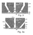
- Figs. 3-3a illustrate diagrammatic representations of a cross-sectional view of a portion of an exemplary print cartridge.
- Fig. 4 illustrates a diagrammatic representation of a cross-sectional view of an exemplary substrate in accordance with one exemplary embodiment.
- Figs. 4a-4b illustrate diagrammatic representations of top and bottom views respectively of the substrate illustrated in Fig. 4 in accordance with one embodiment.
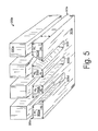
- Fig. 5 illustrates a diagrammatic representation of a perspective view of a portion of a print cartridge in accordance with one exemplary embodiment.
- Fig. 6 illustrates a diagrammatic representation of a top view of an exemplary substrate in accordance with one exemplary embodiment.
- Fig. 6a illustrates a diagrammatic representation of a perspective cut-away view of the exemplary substrate illustrated in Fig. 6 in accordance with one exemplary embodiment.
- Fig. 6b illustrates_a diagrammatic representation of a cross-sectional view of the exemplary substrate illustrated in Fig. 6 in accordance with one exemplary embodiment.
- Fig. 6c illustrates_a diagrammatic representation of a cross-sectional view of an alternative configuration of the view represented in Fig- 6b in accordance with one exemplary embodiment.
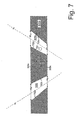
- Fig. 7 illustrates a diagrammatic representation of a cross-sectional view of an exemplary substrate in accordance with one exemplary embodiment.
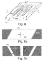
- Fig. 8 illustrates a diagrammatic representation of a perspective view of an exemplary substrate in accordance with one exemplary embodiment.
- Figs. 8a-8b illustrate a diagrammatic representation of cross-sectional views of an exemplary substrate in accordance with one exemplary embodiment.
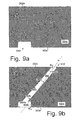
- Figs. 9a-9b illustrate a diagrammatic representation of cross-sectional views of an exemplary substrate in accordance with one exemplary embodiment.
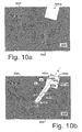
- Figs. 10a-10b illustrate a diagrammatic representation of cross-sectional views of an exemplary substrate in accordance with one exemplary embodiment.
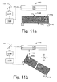
- Figs. 11a-11c illustrate process steps for forming an exemplary substrate in accordance with one exemplary embodiment.
- Feature(s) can have various configurations including blind features and through features.
- a blind feature passes through less than an entirety of the substrate's thickness.
- a feature which extends totally through the thickness becomes a through feature.
- a blind feature may be further processed into a through feature during subsequent processing steps.
- Exemplary substrates having features formed therein can be utilized in various microdevices such as microchips and fluid-ejecting devices among others. Fluid-ejecting devices such as print heads are utilized in printing applications. Fluid-ejecting devices also are utilized in medical and laboratory applications among others. Exemplary substrates also can be utilized in various other applications. For example, display devices may comprise features formed into a glass substrate to create a visual display.
- features comprise fluid-handling slots ("slots"). These techniques can be applicable equally to other types of features formed into a substrate.
- Fig. 1 shows a diagrammatic representation of an exemplary printing device that can utilize an exemplary print cartridge.
- the printing device comprises a printer 100.
- the printer shown here is embodied in the form of an inkjet printer.
- the printer 100 can be capable of printing in black-and-white and/or color.
- the term "printing device" refers to any type of printing device and/or image forming device that employs slotted substrate(s) to achieve at least a portion of its functionality. Examples of such printing devices can include, but are not limited to, printers, facsimile machines, and photocopiers.
- the slotted substrates comprise a portion of a print head which is incorporated into a print cartridge, an example of which is described below.
- Fig. 2 shows a diagrammatic representation of an exemplary print cartridge 202 that can be utilized in an exemplary printing device.
- the print cartridge is comprised of a print head 204 and a cartridge body 206 that supports the print head. Though a single print head 204 is employed on this print cartridge 202 other exemplary configurations may employ multiple print heads on a single print cartridge.
- Print cartridge 202 is configured to have a self-contained fluid or ink supply within cartridge body 206.
- Other print cartridge configurations may alternatively or additionally be configured to receive fluid from an external supply.
- Other exemplary configurations will be recognized by those of skill in the art. Though the term ink is utilized below, it should be understood that fluid-ejecting devices can deliver a diverse range of fluids.
- Print cartridge failure can result from a failure of the print cartridge components. Such component failure can be caused by cracking. As such, various embodiments described below can provide print heads with a reduced propensity to crack.
- Reliability of print cartridge 202 also can be affected by bubbles contained within the print cartridge, especially within the print head 204.
- bubbles can be formed in the ink as a byproduct of operation of a printing device.
- bubbles can be formed as a byproduct of the ejection process in the printing device's print cartridge when ink is ejected from one or more firing chambers of the print head.
- bubbles can occlude ink flow to some or all of the firing chambers and can cause the print head to malfunction.
- Some embodiments can evacuate bubbles from the print head to decrease the likelihood of such a malfunction as will become apparent below.
- An additional desire in designing print cartridges is the reduction of their cost.
- One way to reduce such cost is to reduce the dimensions, and therefore the material and fabrication costs, of print head 204.
- Fig. 3 illustrates a side-sectional diagrammatic representation of a portion of the exemplary print head 204 as indicated in Fig. 2 .
- Fig. 3a illustrates an alternative print head configuration sometimes referred to as an edge feed configuration.
- Fig. 3 The view of Fig. 3 is taken transverse an axis normal to first substrate surface ("first surface”) 302, the axis extending into and out of the plane of the page upon which Fig. 3 appears.
- this axis is the long axis which lies between the first and second surfaces and extends generally parallel to those surfaces.
- a substrate 300 has a thickness t which extends between a first surface 302 and a second substrate surface ("second surface”) 303.
- three features 305a-c comprising fluid-feed slots (“slots”) pass through substrate 300 between first and second surfaces 302, 303.
- the terms "slot" and “feature” are utilized interchangeably. Examples of other feature types are described below in relation to Figs. 9a-9b and Figs. 10a-10b .
- substrate 300 comprises silicon which either can be doped or undoped.
- substrate materials can include, but are not limited to, gallium arsenide, gallium phosphide, indium phosphide, glass, quartz, ceramic or other material.
- Substrate thickness t can have any suitable dimensions that are appropriate for an intended application. In some embodiments substrate thicknesses t can range from less than 100 microns to more than 2000 microns. One exemplary embodiment can utilize a substrate that is approximately 675 microns thick. Though a single substrate is discussed herein, other suitable embodiments may comprise a substrate that has multiple layers during fabrication and/or in the finished product. For example, one such embodiment may employ a substrate having a first component and a second sacrificial component which is discarded at some point during processing.
- one or more thin-film layers 314 are positioned over substrate's second surface 303.
- a barrier layer 316 and an orifice plate or orifice layer 318 are positioned over the thin-film layers 314.
- one or more thin-film layers 314 can comprise one or more conductive traces (not shown) and electrical components such as transistors (not shown), and resistors 320. Individual resistors can be controlled selectively via the electrical traces.
- Thin-film layers 314 also can at least partially define in some embodiments, a wall or surface of multiple fluid-feed passageways 322 through which fluid can pass.
- Thin-film layers 314 also can comprise among others, a field or thermal oxide layer.
- Barrier layer 316 can define, at least in part, multiple firing chambers 324.
- fluid-feed passageways 322 may be defined in barrier layer 316, alone or in combination with thin-film layers 314.
- Orifice layer 318 can define multiple firing nozzles 326. Individual firing nozzles can be aligned respectively with individual firing chambers 324.
- Barrier layer 316 and orifice layer 318 can be formed in any suitable manner.
- both barrier layer 316 and orifice layer 318 comprise thick-film material, such as a photo-imagable polymer material.
- the photo-imagable polymer material can be applied in any suitable manner.
- the material can be "spun-on" as will be recognized by the skilled artisan.
- barrier layer 316 After being spun-on, barrier layer 316 then can be patterned to form, at least in part, desired features such as passageways and firing chambers therein. In one embodiment patterned areas of the barrier layer can be filled with a sacrificial material in what is commonly referred to as a 'lost wax' process.
- orifice layer 318 can be comprised of the same material as the barrier layer and can be formed over barrier layer 316. In one such example orifice layer material can be 'spun-on' over the barrier layer. Orifice layer 318 then can be patterned as desired to form nozzles 326 over respective chambers 324. The sacrificial material then can be removed from the barrier layer's chambers 324 and passageways 322.
- barrier layer 316 comprises a thick-film
- the orifice layer 318 comprises an electroformed nickel or other suitable metal material.
- the orifice layer can be a polymer, such as "Kapton” or “Oriflex", with laser ablated nozzles.
- Other suitable embodiments may employ an orifice layer which performs the functions of both a barrier layer and an orifice layer.
- a housing 330 of cartridge body 206 can be positioned over substrate's first surface 302.
- housing 330 can comprise a polymer, ceramic and/or other suitable material(s).
- An adhesive though not specifically shown, may be utilized to bond or otherwise join housing 330 to substrate 300.
- a fluid such as ink
- Fluid can enter slots 305a-c from the cartridge body 206. Fluid then can flow through individual passageways 322 into an individual firing chamber 324. Fluid can be ejected from the firing chamber when an electrical current is passed through an individual resistor 320 or other ejection means. The electrical current can heat the resistor sufficiently to heat some of the fluid contained in the firing chamber to its boiling point so that it expands to eject a portion of the fluid from a respectively positioned nozzle 326. The ejected fluid then can be replaced by additional fluid from passageway 322.
- slot 305b extends between first and second surfaces 302, 303.
- Slots 305a 1 , 305c 1 extend to second surface 303 from first and second sidewalls 340, 342 that are orthogonal or oblique to the second surface.
- Such a configuration may allow reduced print head die sizes to be used that provide the same functionality as larger die sizes.
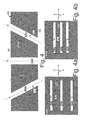
- Fig. 4 illustrates a diagrammatic representation of substrate 300 illustrated in Fig. 3 .
- each slot 305a-c extends through substrate 300 along a bore axis b 1 , b 2 , and b 3 respectively.
- a bore axis intersects the first and second surfaces and can generally correspond to a direction of intended fluid flow through the slot.
- Slot 305b extends along bore axis b 2 which is transverse to second surface 303.
- Slots 305a and 305c extend along bores b 1 , b 3 which are not transverse to second surface 303.
- Individual slots 305a, 305c lie at angles ⁇ 1 , ⁇ 2 with respect to second surface 303.
- Angles ⁇ 1 , ⁇ 2 can comprise any angle less than 90 degrees relative to second surface 303 with some embodiments having a value in the range of 10 degrees to 80 degrees. In some embodiments angles ⁇ 1 , ⁇ 2 can range from about 60 degrees to about 80 degrees. In other embodiments angles ⁇ 1 , ⁇ 2 can range from about 40 degrees to about 59 degrees. In still other embodiments angles ⁇ 1 , ⁇ 2 can range from about 20 degrees to about 39 degrees. In this particular embodiment angles ⁇ 1 , ⁇ 2 each comprise about 62 degrees, another particular embodiment has angles of about 45 degrees. Though in this embodiment angles ⁇ 1 , ⁇ 2 comprise similar values, other embodiments may have dissimilar values.
- angle ⁇ 1 can have a value of 45 degrees while angle ⁇ 2 has a value of 55 degrees.
- Having one or more angled slots can allow greater options in print cartridge design, as well in the design of other microdevices, as will be described in more detail below.
- slots 305a, 305c are angled relative the second surface 303 when viewed transverse the long axis.
- other embodiments may be angled relative to second surface 303 when viewed along the long axis. Examples of such a configuration will be described in more detail below in relation to Figs. 8-8b .
- Embodiments having one or more angled slots can allow greater design flexibility. For example, angled slots can allow a first geometry at first surface 302 and a second different geometry at second surface 303.
- Figs. 4a and 4b illustrate top views of substrate's first surface 302 and second surface 303 respectively.
- slots 305a-305c define a first footprint 402a at first surface 302 and a second different footprint 402b at second surface 303.
- First footprint 402a defines a first area while second footprint 402b defines a second area.
- the first area can be at least about 10 percent greater than the second area.
- first area is about 20 percent greater than second area.
- the increased area is due predominately to a greater width w a of footprint 402a when compared to width w b of footprint 402b.
- Fig. 5 shows a cut-away perspective view of a portion of another exemplary print cartridge 202a.
- Substrate 300a is positioned proximate housing 330a in an orientation in which the two components might be bonded together to form print cartridge 202a.
- three slots 305d-305f are defined, at least in part, by substrate material remaining between the slots.
- This substrate material remaining between the slots is referred to herein as "beam(s)" 502a-502d which extend generally parallel to the long axis of the slots.
- Beams 502a and 502d can be referred to as external beams as they define a slot on one side and a substrate edge on the other.
- beams 502b-502c can be referred to as internal beams as they define slots on two sides.
- Beams 502a-502d have widths w 1 - w 4 respectively at first surface 302a as measured transverse the slots' long axes.
- Some print cartridge designs achieve effective integration of substrate 300a with cartridge body housing 330a by maintaining the widest possible beam width of the substrate's narrowest beam relative to first surface 302a. Such a configuration can among other factors aid in molding cartridge body housing 330a.
- beam widths w 1 - w 4 are generally equal.
- Beams 502a-502d also define widths w 5 - w 8 respectively at second surface 303a as measured transverse the slots' long axes.
- Some print cartridge designs configure substrate's second surface 303a so that external beams 502a, 502d are relatively wider than internal beams 502b, 502c to allow placement of various electrical components overlying second surface 303a on the external beams.
- print head substrate 300a incorporating one or more angled slots can achieve both a desired first surface configuration and a desired second surface configuration.
- internal beams 502b, 502c of substrate 300a are stronger and less likely to crack than a configuration where second surface widths w 6 , w 7 are maintained through the substrate' thickness t .
- the embodiment shown in Fig. 5 has generally continuous slots when viewed along the long axis.
- Other embodiments may have substrate material or 'ribs' extending across the substrate's long axis from a beam defining one side of a slot to another beam defining an opposing side of the slot.
- Figs. 6-6c illustrate one example where ribs 602 extend generally across an axis of slots 305g-305i.
- Fig. 6 illustrates a top view of substrate's second surface 303b.
- Fig. 6a illustrates a cut-away view of substrate 300b as indicated in Fig. 6.
- Figs. 6b-6c illustrate views taken generally orthogonally to the y -axis which provide two exemplary rib configurations.
- ribs 602 extend between beams 502e and 502f, beams 502f and 502g, and beams 502g and 502h.
- Fig. 6b illustrates rib 602 illustrated in Fig. 6a in a little more detail, while Fig. 6c comprises a view similar to that illustrated in Fig. 6b of another exemplary rib configuration.
- Fig. 6b illustrates an embodiment where rib 602 tapers from a first width w 1 proximate first surface 302b to a second width w 2 proximate second surface 303b.
- This is but one exemplary configuration.
- other embodiments may maintain a generally uniform width between the first and second surfaces.
- rib 602 can approximate a frustrum.
- Such a configuration may supply generally uniform fluid flow to various chambers, described above, which can be supplied by slot 305g.
- Other embodiments may utilize other rib shapes.
- height h of rib 602 equals thickness t of substrate 300b.
- Fig. 6c illustrates an alternative configuration where rib height h is less than thickness t .
- rib 602a extends from first surface 302b but does not reach second surface 303b.
- Configurations which utilize a height h less than thickness t may contribute to a uniform fluid environment for various chambers supplied by slot 305g.
- Fig. 7 illustrates a cross-sectional representation of another exemplary substrate 300c.
- This cross-sectional view is similar to the view illustrated in Fig. 4 and is transverse the long axis.
- Two slots 305j, 305k extend through substrate 300c along bores b 4 , b 5 respectively which are not transverse to first surface 302c.
- bores b 4 , b 5 intersect midpoints of widths w 8 , w 9 and w 10 , w 11 respectively.
- slot 305j is defined, at least in part, by a first sidewall 702a and a second sidewall 702b.
- slot 305k is defined, at least in part, by a first sidewall 702c and a second sidewall 702d.
- bubbles may occur.
- Some of the described embodiments can allow a bubble to evacuate more readily from the print head compared to a traditional print head design.
- a bubble is indicated generally at 704.
- Buoyancy forces acting upon bubble 704 are directed along the z -axis.
- Fluid flow along bore b 5 can be represented as a vector having both y -axis and z -axis components. Generally only the z -axis component of the fluid flow acts against the bubble's buoyancy forces and the bubble is more likely to migrate toward first surface 302c and ultimately from the slot.
- bubble 704 may migrate toward first sidewall 702c and then up the first sidewall toward first surface 302c.
- the bubbles may migrate toward and up first sidewall 702c. Following a common path may tend to force the bubbles together leading to agglomeration. If the bubbles agglomerate they may pass out of the slot more quickly than they otherwise would. Agglomeration may assist with bubble removal because the buoyant force acts to move the bubble upwards against the ink flow. This buoyant force may become increasingly dominant as the bubbles agglomerate and grow because it increases with the cube of the bubble diameter whereas the drag force induced by the downward ink flow increases only with the square of the bubble diameter.
- width w 8 of slot 305j at first surface 302c is greater than width w 9 at second surface 303c.
- width w 10 of slot 305k at first surface 302c is greater than width w 11 at second surface 303c.
- slots 305j, 305k have a slot profile which generally increases from second surface 303c toward first surface 302c. As such if bubble 704 has a volume sufficient to contact both sidewalls 702c, 702d simultaneously the less constrictive width environment progressively available toward first surface 302c can provide a driving force to move bubble 704 toward the first surface 302c and ultimately out of the print head.
- Figs. 8-8b represent another substrate 300d.
- Fig. 8 represents a perspective view
- Fig. 8a represents a cross-sectional view taken along line a-a indicated in Fig. 8
- Fig. 8b represents a cross-sectional view taken along line b-b.
- line a-a is generally parallel to a long axis of slot 3051 and line b-b is generally orthogonal the long axis.
- slot 3051 when viewed along its long axis slot 3051 generally approximates a portion of a parallelogram 804 as best can be appreciated from Fig. 8a . Also, in this particular embodiment slot 3051 approximates a portion of a parallelogram 806 when viewed transverse the long axis as best can be appreciated from Fig. 8b .
- Other slots can approximate other geometric shapes. Various slot shapes can allow increased flexibility of print head design over standard slot configurations.
- Figs. 9a-9b and 10a-10b represent exemplary features and process steps for forming the features.
- the term feature is employed.
- the feature may be a bind feature or a through feature comprising a slot.
- Figs. 9a-9b represent cross-sectional views of substrate 300e.
- Fig. 9a represents an intermediary step in forming a feature in the substrate
- Fig. 9b represents feature 905 formed in substrate 300e.
- Feature 905 can be utilized as a fluid-handling slot or electrical interconnect, e.g. a via, among other uses.
- Feature 905 defines a bore axis b 7 which is not transverse first surface 302e and which intersects a midpoint of the feature width w 12 , w 13 at the first surface 302e and the second surface 303e respectively.
- Feature 905 is defined, at least in part, by one or more sidewalls.
- two sidewalls 902a, 902b are indicated.
- individual sidewalls 902a, 902b have a first sidewall portion 904a, 904b respectively that is generally transverse to first surface 302e.
- individual sidewalls 902a, 902b have a second different sidewall portion 906a, 906b that is not transverse the first surface.
- Feature 905 can be formed with one or more substrate removal techniques. Examples of suitable substrate removal techniques are described below in relation to Fig. 11a-11c .
- One suitable formation method can involve removing substrate material from second surface 303e as indicated generally at 910.
- the substrate removal process indicated at 910 can form first sidewall portions 904a, 904b.
- the same removal process and/or one or more different removal processes can be utilized to remove substrate material indicated generally at 912.
- the sidewall removal process indicated generally at 912 can form sidewall portions 906a, 906b.
- the second removal process can be accomplished from either first surface 302e, second surface 303e or a combination thereof.
- Other embodiments may conduct the substrate removal process indicated at 912 before the substrate removal process indicated at 910.
- Figs. 10a-10b show feature 905a formed in substrate 300f.
- Feature 905a defines a bore axis b 8 which is not transverse first surface 302f and intersects a midpoint of the feature width w 14 , w 15 at the first surface 302f and at a bottom surface 1000 respectively.
- feature 905a can comprise a first region 1001a and a second region 1001b.
- the two regions 1001a, 1001b can be formed in distinct steps or as a single process.
- Feature 905a can be defined, at least in part, by one or more sidewalls.
- two sidewalls 1002a, 1002b are indicated.
- individual sidewalls 1002a, 1002b have a first sidewall portion 1004a, 1004b respectively that is not transverse to first surface 302f and lies at a first angle ⁇ 4 relative to first surface 302f.
- individual sidewalls 1002a, 1002b have a second different sidewall portion 1006a, 1006b respectively that is not transverse the first surface and which lies at a second different angle ⁇ 5 relative to first surface 302f.
- These exemplary sidewall configurations can allow greater microdevice design flexibility.
- Figs. 11a-11c show process steps for forming an exemplary feature in a substrate.
- Fig. 11a illustrates a laser machine 1102 for removing substrate material sufficient to form feature 905b in a substrate.
- Feature 905b generally can approximate a circle, an ellipsoid, a rectangle, or any other desired shape whether regular or irregular.
- an individual substrate 300g is illustrated here. Other embodiments may act upon a wafer or other material which subsequently can be separated or can be diced into individual substrates.
- laser machine 1102 comprises a laser source 1106 configured to generate laser beam 1108 for laser machining substrate 300g.
- Exemplary laser beams such as laser beam 1108 can provide sufficient energy to energize substrate material at which the laser beam is directed.
- Energizing can comprise melting, vaporizing, exfoliating, phase exploding, ablating, reacting, and/or a combination thereof, among others processes.
- Some exemplary laser machines may utilize a gas assist and/or liquid assist process to aid in substrate removal.
- substrate 300g is positioned on a fixture or stage 1112 for processing.
- Suitable fixtures should be recognized by the skilled artisan. Some such fixtures may be configured to move the substrate along x, y, and/or z coordinates.
- Various exemplary embodiments can utilize one or more mirrors 1114, galvanometers 1116 and/or lenses 1118 to direct laser beam 1108 at first surface 302g.
- laser beam 1108 can be focused in order to increase its energy density to machine the substrate more effectively.
- the laser beam can be focused to achieve a desired beam geometry where the laser beam contacts the substrate 300g.
- Laser machine 1102 further includes a controller 1120 coupled to laser source 1106, stage 1112, and galvanometer 1116.
- Controller 1120 can comprise a processor for executing computer readable instructions contained on one or more of hardware, software, and firmware. Controller 1120 can control laser source 1106, stage 1112 and/or galvanometer 1116 to form feature 905b. Other embodiments may control some or all of the processes manually or with a combination of controllers and manual operation.
- laser beam 1108 is forming feature 905b into substrate 300g.
- Feature 905b is formed with stage 1112 orienting substrate's first surface 302g generally transverse to laser beam 1108.
- Feature 905b extends along a bore axis which is generally transverse to first surface 302g. In this instance the bore axis of feature 905b can be represented by laser beam 1108 proximate the substrate.
- Fig. 11b illustrates a subsequent process step where stage 1112 has repositioned substrate 300g to form feature 905c.
- stage 1112 can orient substrate 300g at an angle ⁇ less than 90 degrees relative to laser beam 1108.
- Various embodiments can utilize angles ranging from about 10 degrees to about 80 degrees.
- angle ⁇ can range from about 60 degrees to about 80 degrees.
- angle ⁇ can range from about 40 degrees to about 59 degrees.
- angle ⁇ can range from about 20 degrees to about 39 degrees.
- angle ⁇ comprises about 70 degrees.
- adjustments can be made to stage 1112, lens 1118 and/or galvanometer 1116 to maintain focus of the laser beam on the substrate.
- Fig. 11b illustrates one exemplary configuration where stage 1112 and substrate 300g are angled relative to laser beam 1108, other exemplary configurations may angle the laser beam and/or laser machine relative to the substrate to achieve a desired orientation. Still other embodiments may angle both the laser beam and the substrate to achieve a desired orientation of the laser beam to the substrate.
- Fig. 11c illustrates a further process step forming another feature 905d.
- Stage 1112 repositioned substrate 300g relative to laser beam 1108 to form feature 905d having a desired orientation.
- the skilled artisan should recognize other suitable configurations.
Landscapes
- Engineering & Computer Science (AREA)
- Manufacturing & Machinery (AREA)
- Physics & Mathematics (AREA)
- Optics & Photonics (AREA)
- Particle Formation And Scattering Control In Inkjet Printers (AREA)
- Coating Apparatus (AREA)
- Pressure Sensors (AREA)
- Physical Or Chemical Processes And Apparatus (AREA)
- Micromachines (AREA)
Abstract
Description
- Many microdevices include substrates having features formed therein. Existing feature shapes, dimensions, and/or orientations can limit microdevice design.
- The same components are used throughout the drawings to reference like features and components wherever feasible. Alphabetic suffixes are utilized to designate different embodiments.
-
Fig. 1 illustrates a front elevational view of a diagrammatic representation of an exemplary printer in accordance with one exemplary embodiment. -
Fig. 2 illustrates a perspective view of a diagrammatic representation of a print cartridge suitable for use in the exemplary printer shown inFig. 1 in accordance with one exemplary embodiment. -
Figs. 3-3a illustrate diagrammatic representations of a cross-sectional view of a portion of an exemplary print cartridge. -
Fig. 4 illustrates a diagrammatic representation of a cross-sectional view of an exemplary substrate in accordance with one exemplary embodiment. -
Figs. 4a-4b illustrate diagrammatic representations of top and bottom views respectively of the substrate illustrated inFig. 4 in accordance with one embodiment. -
Fig. 5 illustrates a diagrammatic representation of a perspective view of a portion of a print cartridge in accordance with one exemplary embodiment. -
Fig. 6 illustrates a diagrammatic representation of a top view of an exemplary substrate in accordance with one exemplary embodiment. -
Fig. 6a illustrates a diagrammatic representation of a perspective cut-away view of the exemplary substrate illustrated inFig. 6 in accordance with one exemplary embodiment. -
Fig. 6b illustrates_a diagrammatic representation of a cross-sectional view of the exemplary substrate illustrated inFig. 6 in accordance with one exemplary embodiment. -
Fig. 6c illustrates_a diagrammatic representation of a cross-sectional view of an alternative configuration of the view represented in Fig- 6b in accordance with one exemplary embodiment. -
Fig. 7 illustrates a diagrammatic representation of a cross-sectional view of an exemplary substrate in accordance with one exemplary embodiment. -
Fig. 8 illustrates a diagrammatic representation of a perspective view of an exemplary substrate in accordance with one exemplary embodiment. -
Figs. 8a-8b illustrate a diagrammatic representation of cross-sectional views of an exemplary substrate in accordance with one exemplary embodiment. -
Figs. 9a-9b illustrate a diagrammatic representation of cross-sectional views of an exemplary substrate in accordance with one exemplary embodiment. -
Figs. 10a-10b illustrate a diagrammatic representation of cross-sectional views of an exemplary substrate in accordance with one exemplary embodiment. -
Figs. 11a-11c illustrate process steps for forming an exemplary substrate in accordance with one exemplary embodiment. - The embodiments described below pertain to methods and systems for forming features in a substrate and to microdevices incorporating such substrates. Feature(s) can have various configurations including blind features and through features. A blind feature passes through less than an entirety of the substrate's thickness. A feature which extends totally through the thickness becomes a through feature. A blind feature may be further processed into a through feature during subsequent processing steps.
- Exemplary substrates having features formed therein can be utilized in various microdevices such as microchips and fluid-ejecting devices among others. Fluid-ejecting devices such as print heads are utilized in printing applications. Fluid-ejecting devices also are utilized in medical and laboratory applications among others. Exemplary substrates also can be utilized in various other applications. For example, display devices may comprise features formed into a glass substrate to create a visual display.
- Several embodiments are provided below where the features comprise fluid-handling slots ("slots"). These techniques can be applicable equally to other types of features formed into a substrate.
- Slotted substrates can be incorporated into fluid ejection devices such as ink jet print heads and/or print cartridges, among other uses. The various components described below may not be illustrated to scale. Rather, the included figures are intended as diagrammatic representations to illustrate to the reader various inventive principles that are described herein.
-
Fig. 1 shows a diagrammatic representation of an exemplary printing device that can utilize an exemplary print cartridge. In this embodiment the printing device comprises aprinter 100. The printer shown here is embodied in the form of an inkjet printer. Theprinter 100 can be capable of printing in black-and-white and/or color. The term "printing device" refers to any type of printing device and/or image forming device that employs slotted substrate(s) to achieve at least a portion of its functionality. Examples of such printing devices can include, but are not limited to, printers, facsimile machines, and photocopiers. In this exemplary printing device the slotted substrates comprise a portion of a print head which is incorporated into a print cartridge, an example of which is described below. -
Fig. 2 shows a diagrammatic representation of anexemplary print cartridge 202 that can be utilized in an exemplary printing device. The print cartridge is comprised of aprint head 204 and acartridge body 206 that supports the print head. Though asingle print head 204 is employed on thisprint cartridge 202 other exemplary configurations may employ multiple print heads on a single print cartridge. -
Print cartridge 202 is configured to have a self-contained fluid or ink supply withincartridge body 206. Other print cartridge configurations may alternatively or additionally be configured to receive fluid from an external supply. Other exemplary configurations will be recognized by those of skill in the art. Though the term ink is utilized below, it should be understood that fluid-ejecting devices can deliver a diverse range of fluids. - Reliability of
print cartridge 202 is desirable for proper functioning ofprinter 100. Further, failure of print cartridges during manufacture increases production costs. Print cartridge failure can result from a failure of the print cartridge components. Such component failure can be caused by cracking. As such, various embodiments described below can provide print heads with a reduced propensity to crack. - Reliability of
print cartridge 202 also can be affected by bubbles contained within the print cartridge, especially within theprint head 204. Among other origins, bubbles can be formed in the ink as a byproduct of operation of a printing device. For example, bubbles can be formed as a byproduct of the ejection process in the printing device's print cartridge when ink is ejected from one or more firing chambers of the print head. - If bubbles accumulate within the print head the bubbles can occlude ink flow to some or all of the firing chambers and can cause the print head to malfunction. Some embodiments can evacuate bubbles from the print head to decrease the likelihood of such a malfunction as will become apparent below.
- An additional desire in designing print cartridges, is the reduction of their cost. One way to reduce such cost, is to reduce the dimensions, and therefore the material and fabrication costs, of
print head 204. -
Fig. 3 illustrates a side-sectional diagrammatic representation of a portion of theexemplary print head 204 as indicated inFig. 2 .Fig. 3a illustrates an alternative print head configuration sometimes referred to as an edge feed configuration. - The view of
Fig. 3 is taken transverse an axis normal to first substrate surface ("first surface") 302, the axis extending into and out of the plane of the page upon whichFig. 3 appears. In this particular embodiment this axis is the long axis which lies between the first and second surfaces and extends generally parallel to those surfaces. Here asubstrate 300 has a thickness t which extends between afirst surface 302 and a second substrate surface ("second surface") 303. In this embodiment threefeatures 305a-c comprising fluid-feed slots ("slots") pass throughsubstrate 300 between first andsecond surfaces Figs. 9a-9b andFigs. 10a-10b . - In this particular embodiment,
substrate 300 comprises silicon which either can be doped or undoped. Other substrate materials can include, but are not limited to, gallium arsenide, gallium phosphide, indium phosphide, glass, quartz, ceramic or other material. - Substrate thickness t can have any suitable dimensions that are appropriate for an intended application. In some embodiments substrate thicknesses t can range from less than 100 microns to more than 2000 microns. One exemplary embodiment can utilize a substrate that is approximately 675 microns thick. Though a single substrate is discussed herein, other suitable embodiments may comprise a substrate that has multiple layers during fabrication and/or in the finished product. For example, one such embodiment may employ a substrate having a first component and a second sacrificial component which is discarded at some point during processing.
- In this particular embodiment, one or more thin-
film layers 314 are positioned over substrate'ssecond surface 303. In at least some embodiments, wheresubstrate 300 is incorporated into a fluid ejection device, abarrier layer 316 and an orifice plate ororifice layer 318 are positioned over the thin-film layers 314. - In one embodiment one or more thin-
film layers 314 can comprise one or more conductive traces (not shown) and electrical components such as transistors (not shown), andresistors 320. Individual resistors can be controlled selectively via the electrical traces. Thin-film layers 314 also can at least partially define in some embodiments, a wall or surface of multiple fluid-feed passageways 322 through which fluid can pass. Thin-film layers 314 also can comprise among others, a field or thermal oxide layer.Barrier layer 316 can define, at least in part, multiple firingchambers 324. In some embodiments fluid-feed passageways 322 may be defined inbarrier layer 316, alone or in combination with thin-film layers 314.Orifice layer 318 can definemultiple firing nozzles 326. Individual firing nozzles can be aligned respectively withindividual firing chambers 324. -
Barrier layer 316 andorifice layer 318 can be formed in any suitable manner. In one particular implementation bothbarrier layer 316 andorifice layer 318 comprise thick-film material, such as a photo-imagable polymer material. The photo-imagable polymer material can be applied in any suitable manner. For example, the material can be "spun-on" as will be recognized by the skilled artisan. - After being spun-on,
barrier layer 316 then can be patterned to form, at least in part, desired features such as passageways and firing chambers therein. In one embodiment patterned areas of the barrier layer can be filled with a sacrificial material in what is commonly referred to as a 'lost wax' process. In thisembodiment orifice layer 318 can be comprised of the same material as the barrier layer and can be formed overbarrier layer 316. In one such example orifice layer material can be 'spun-on' over the barrier layer.Orifice layer 318 then can be patterned as desired to formnozzles 326 overrespective chambers 324. The sacrificial material then can be removed from the barrier layer'schambers 324 and passageways 322. - In another embodiment,
barrier layer 316 comprises a thick-film, while theorifice layer 318 comprises an electroformed nickel or other suitable metal material. Alternatively the orifice layer can be a polymer, such as "Kapton" or "Oriflex", with laser ablated nozzles. Other suitable embodiments may employ an orifice layer which performs the functions of both a barrier layer and an orifice layer. - A
housing 330 ofcartridge body 206 can be positioned over substrate'sfirst surface 302. In some embodiments,housing 330 can comprise a polymer, ceramic and/or other suitable material(s). An adhesive, though not specifically shown, may be utilized to bond or otherwise joinhousing 330 tosubstrate 300. - In operation, a fluid, such as ink, can enter
slots 305a-c from thecartridge body 206. Fluid then can flow through individual passageways 322 into anindividual firing chamber 324. Fluid can be ejected from the firing chamber when an electrical current is passed through anindividual resistor 320 or other ejection means. The electrical current can heat the resistor sufficiently to heat some of the fluid contained in the firing chamber to its boiling point so that it expands to eject a portion of the fluid from a respectively positionednozzle 326. The ejected fluid then can be replaced by additional fluid from passageway 322. - As represented in
Fig. 3a ,slot 305b, extends between first andsecond surfaces Slots second surface 303 from first andsecond sidewalls -
Fig. 4 illustrates a diagrammatic representation ofsubstrate 300 illustrated inFig. 3 . In this embodiment eachslot 305a-c extends throughsubstrate 300 along a bore axis b 1, b 2, and b 3 respectively. A bore axis intersects the first and second surfaces and can generally correspond to a direction of intended fluid flow through the slot.Slot 305b extends along bore axis b 2 which is transverse tosecond surface 303.Slots second surface 303.Individual slots second surface 303. - Angles α1, α2 can comprise any angle less than 90 degrees relative to
second surface 303 with some embodiments having a value in the range of 10 degrees to 80 degrees. In some embodiments angles α1, α2 can range from about 60 degrees to about 80 degrees. In other embodiments angles α1, α2 can range from about 40 degrees to about 59 degrees. In still other embodiments angles α1, α2 can range from about 20 degrees to about 39 degrees. In this particular embodiment angles α1, α2 each comprise about 62 degrees, another particular embodiment has angles of about 45 degrees. Though in this embodiment angles α1, α2 comprise similar values, other embodiments may have dissimilar values. For example in an alternative embodiment angle α1, can have a value of 45 degrees while angle α2 has a value of 55 degrees. Having one or more angled slots can allow greater options in print cartridge design, as well in the design of other microdevices, as will be described in more detail below. - In this
embodiment slots second surface 303 when viewed transverse the long axis. Alternatively or additionally, other embodiments may be angled relative tosecond surface 303 when viewed along the long axis. Examples of such a configuration will be described in more detail below in relation toFigs. 8-8b . Embodiments having one or more angled slots can allow greater design flexibility. For example, angled slots can allow a first geometry atfirst surface 302 and a second different geometry atsecond surface 303. -
Figs. 4a and 4b illustrate top views of substrate'sfirst surface 302 andsecond surface 303 respectively. In thisembodiment slots 305a-305c define afirst footprint 402a atfirst surface 302 and a seconddifferent footprint 402b atsecond surface 303.First footprint 402a defines a first area whilesecond footprint 402b defines a second area. In some embodiments the first area can be at least about 10 percent greater than the second area. In this particular embodiment first area is about 20 percent greater than second area. Further, in this embodiment the increased area is due predominately to a greater width w a offootprint 402a when compared to width w b offootprint 402b. -
Fig. 5 shows a cut-away perspective view of a portion of anotherexemplary print cartridge 202a. Substrate 300a is positionedproximate housing 330a in an orientation in which the two components might be bonded together to formprint cartridge 202a. In this embodiment threeslots 305d-305f are defined, at least in part, by substrate material remaining between the slots. This substrate material remaining between the slots is referred to herein as "beam(s)" 502a-502d which extend generally parallel to the long axis of the slots.Beams Beams 502a-502d have widths w 1-w 4 respectively atfirst surface 302a as measured transverse the slots' long axes. - Some print cartridge designs achieve effective integration of substrate 300a with
cartridge body housing 330a by maintaining the widest possible beam width of the substrate's narrowest beam relative tofirst surface 302a. Such a configuration can among other factors aid in moldingcartridge body housing 330a. In this illustrated embodiment beam widths w 1-w 4 are generally equal. -
Beams 502a-502d also define widths w 5-w 8 respectively atsecond surface 303a as measured transverse the slots' long axes. Some print cartridge designs configure substrate'ssecond surface 303a so thatexternal beams internal beams second surface 303a on the external beams. As shown inFig. 5 print head substrate 300a incorporating one or more angled slots can achieve both a desired first surface configuration and a desired second surface configuration. Further,internal beams - The embodiment shown in
Fig. 5 has generally continuous slots when viewed along the long axis. Other embodiments may have substrate material or 'ribs' extending across the substrate's long axis from a beam defining one side of a slot to another beam defining an opposing side of the slot. -
Figs. 6-6c illustrate one example whereribs 602 extend generally across an axis ofslots 305g-305i.Fig. 6 illustrates a top view of substrate'ssecond surface 303b.Fig. 6a illustrates a cut-away view ofsubstrate 300b as indicated inFig. 6. Figs. 6b-6c illustrate views taken generally orthogonally to the y-axis which provide two exemplary rib configurations. - As illustrated in
Figs. 6- 6a ribs 602 extend betweenbeams beams 502f and 502g, and beams 502g and 502h.Fig. 6b illustratesrib 602 illustrated inFig. 6a in a little more detail, whileFig. 6c comprises a view similar to that illustrated inFig. 6b of another exemplary rib configuration. -
Fig. 6b illustrates an embodiment whererib 602 tapers from a first width w 1 proximatefirst surface 302b to a second width w 2 proximatesecond surface 303b. This is but one exemplary configuration. For example other embodiments may maintain a generally uniform width between the first and second surfaces. In thisinstance rib 602 can approximate a frustrum. Such a configuration may supply generally uniform fluid flow to various chambers, described above, which can be supplied byslot 305g. Other embodiments may utilize other rib shapes. In the embodiment illustrated inFigs. 6a-6b height h ofrib 602 equals thickness t ofsubstrate 300b. -
Fig. 6c illustrates an alternative configuration where rib height h is less than thickness t. In thisparticular instance rib 602a extends fromfirst surface 302b but does not reachsecond surface 303b. Configurations which utilize a height h less than thickness t may contribute to a uniform fluid environment for various chambers supplied byslot 305g. -
Fig. 7 illustrates a cross-sectional representation of anotherexemplary substrate 300c. This cross-sectional view is similar to the view illustrated inFig. 4 and is transverse the long axis. Twoslots 305j, 305k extend throughsubstrate 300c along bores b 4, b 5 respectively which are not transverse tofirst surface 302c. In this instance bores b 4, b 5 intersect midpoints of widths w 8, w 9 and w 10, w 11 respectively. - In this embodiment slot 305j is defined, at least in part, by a
first sidewall 702a and asecond sidewall 702b. Similarly,slot 305k is defined, at least in part, by afirst sidewall 702c and asecond sidewall 702d. - During operation of a print
cartridge incorporating substrate 300c bubbles may occur. Some of the described embodiments can allow a bubble to evacuate more readily from the print head compared to a traditional print head design. In this particular embodiment, a bubble is indicated generally at 704. Buoyancy forces acting uponbubble 704 are directed along the z-axis. Fluid flow along bore b 5 can be represented as a vector having both y-axis and z-axis components. Generally only the z-axis component of the fluid flow acts against the bubble's buoyancy forces and the bubble is more likely to migrate towardfirst surface 302c and ultimately from the slot. In someinstances bubble 704 may migrate towardfirst sidewall 702c and then up the first sidewall towardfirst surface 302c. - Where multiple bubbles occur the bubbles may migrate toward and up
first sidewall 702c. Following a common path may tend to force the bubbles together leading to agglomeration. If the bubbles agglomerate they may pass out of the slot more quickly than they otherwise would. Agglomeration may assist with bubble removal because the buoyant force acts to move the bubble upwards against the ink flow. This buoyant force may become increasingly dominant as the bubbles agglomerate and grow because it increases with the cube of the bubble diameter whereas the drag force induced by the downward ink flow increases only with the square of the bubble diameter. - As represented in
Fig. 7 width w 8 of slot 305j atfirst surface 302c is greater than width w 9 atsecond surface 303c. Similarly, width w 10 ofslot 305k atfirst surface 302c is greater than width w 11 atsecond surface 303c. In thisembodiment slots 305j, 305k have a slot profile which generally increases fromsecond surface 303c towardfirst surface 302c. As such ifbubble 704 has a volume sufficient to contact bothsidewalls first surface 302c can provide a driving force to movebubble 704 toward thefirst surface 302c and ultimately out of the print head. -
Figs. 8-8b represent anothersubstrate 300d.Fig. 8 represents a perspective view, whileFig. 8a represents a cross-sectional view taken along line a-a indicated inFig. 8 and Fig. 8b represents a cross-sectional view taken along line b-b. In this embodiment line a-a is generally parallel to a long axis ofslot 3051 and line b-b is generally orthogonal the long axis. - In this embodiment, when viewed along its
long axis slot 3051 generally approximates a portion of aparallelogram 804 as best can be appreciated fromFig. 8a . Also, in thisparticular embodiment slot 3051 approximates a portion of aparallelogram 806 when viewed transverse the long axis as best can be appreciated fromFig. 8b . Other slots can approximate other geometric shapes. Various slot shapes can allow increased flexibility of print head design over standard slot configurations. -
Figs. 9a-9b and10a-10b represent exemplary features and process steps for forming the features. In these two embodiments the term feature is employed. The feature may be a bind feature or a through feature comprising a slot. -
Figs. 9a-9b represent cross-sectional views ofsubstrate 300e.Fig. 9a represents an intermediary step in forming a feature in the substrate, whileFig. 9b represents feature 905 formed insubstrate 300e. Feature 905 can be utilized as a fluid-handling slot or electrical interconnect, e.g. a via, among other uses.Feature 905 defines a bore axis b 7 which is not transversefirst surface 302e and which intersects a midpoint of the feature width w 12, w 13 at thefirst surface 302e and thesecond surface 303e respectively. -
Feature 905 is defined, at least in part, by one or more sidewalls. In this embodiment two sidewalls 902a, 902b are indicated. Also in this embodiment individual sidewalls 902a, 902b have afirst sidewall portion first surface 302e. Further in this embodiment individual sidewalls 902a, 902b have a seconddifferent sidewall portion - Feature 905 can be formed with one or more substrate removal techniques. Examples of suitable substrate removal techniques are described below in relation to
Fig. 11a-11c . One suitable formation method can involve removing substrate material fromsecond surface 303e as indicated generally at 910. The substrate removal process indicated at 910 can formfirst sidewall portions sidewall portions first surface 302e,second surface 303e or a combination thereof. Other embodiments may conduct the substrate removal process indicated at 912 before the substrate removal process indicated at 910. -
Figs. 10a- 10b show feature 905a formed insubstrate 300f.Feature 905a defines a bore axis b 8 which is not transversefirst surface 302f and intersects a midpoint of the feature width w 14, w 15 at thefirst surface 302f and at abottom surface 1000 respectively. In thisembodiment feature 905a can comprise afirst region 1001a and asecond region 1001b. In some embodiments the tworegions -
Feature 905a can be defined, at least in part, by one or more sidewalls. In this embodiment two sidewalls 1002a, 1002b are indicated. Also in this embodiment individual sidewalls 1002a, 1002b have afirst sidewall portion first surface 302f and lies at a first angle α4 relative tofirst surface 302f..Further in this embodiment individual sidewalls 1002a, 1002b have a seconddifferent sidewall portion first surface 302f. These exemplary sidewall configurations can allow greater microdevice design flexibility. -
Figs. 11a-11c show process steps for forming an exemplary feature in a substrate. -
Fig. 11a , illustrates alaser machine 1102 for removing substrate material sufficient to formfeature 905b in a substrate.Feature 905b generally can approximate a circle, an ellipsoid, a rectangle, or any other desired shape whether regular or irregular. For purposes of explanation, anindividual substrate 300g is illustrated here. Other embodiments may act upon a wafer or other material which subsequently can be separated or can be diced into individual substrates. - In this embodiment,
laser machine 1102 comprises alaser source 1106 configured to generatelaser beam 1108 forlaser machining substrate 300g. Exemplary laser beams such aslaser beam 1108 can provide sufficient energy to energize substrate material at which the laser beam is directed. Energizing can comprise melting, vaporizing, exfoliating, phase exploding, ablating, reacting, and/or a combination thereof, among others processes. Some exemplary laser machines may utilize a gas assist and/or liquid assist process to aid in substrate removal. - In this
embodiment substrate 300g is positioned on a fixture orstage 1112 for processing. Suitable fixtures should be recognized by the skilled artisan. Some such fixtures may be configured to move the substrate along x, y, and/or z coordinates. - Various exemplary embodiments can utilize one or
more mirrors 1114,galvanometers 1116 and/orlenses 1118 to directlaser beam 1108 atfirst surface 302g. In some embodiments,laser beam 1108 can be focused in order to increase its energy density to machine the substrate more effectively. In these exemplary embodiments the laser beam can be focused to achieve a desired beam geometry where the laser beam contacts thesubstrate 300g. -
Laser machine 1102 further includes acontroller 1120 coupled tolaser source 1106,stage 1112, andgalvanometer 1116.Controller 1120 can comprise a processor for executing computer readable instructions contained on one or more of hardware, software, and firmware.Controller 1120 can controllaser source 1106,stage 1112 and/orgalvanometer 1116 to formfeature 905b. Other embodiments may control some or all of the processes manually or with a combination of controllers and manual operation. - As illustrated in
Fig. 11a ,laser beam 1108 is formingfeature 905b intosubstrate 300g.Feature 905b is formed withstage 1112 orienting substrate'sfirst surface 302g generally transverse tolaser beam 1108.Feature 905b extends along a bore axis which is generally transverse tofirst surface 302g. In this instance the bore axis offeature 905b can be represented bylaser beam 1108 proximate the substrate. -
Fig. 11b illustrates a subsequent process step wherestage 1112 has repositionedsubstrate 300g to formfeature 905c. In thisembodiment stage 1112 can orientsubstrate 300g at an angle β less than 90 degrees relative tolaser beam 1108. Various embodiments can utilize angles ranging from about 10 degrees to about 80 degrees. In some embodiments angle β can range from about 60 degrees to about 80 degrees. In other embodiments angle β can range from about 40 degrees to about 59 degrees. In still other embodiments angle β can range from about 20 degrees to about 39 degrees. In this particular embodiment angle β comprises about 70 degrees. During laser machining, adjustments can be made to stage 1112,lens 1118 and/orgalvanometer 1116 to maintain focus of the laser beam on the substrate. This process can be utilized to form blind features and/or through features. ThoughFig. 11b illustrates one exemplary configuration wherestage 1112 andsubstrate 300g are angled relative tolaser beam 1108, other exemplary configurations may angle the laser beam and/or laser machine relative to the substrate to achieve a desired orientation. Still other embodiments may angle both the laser beam and the substrate to achieve a desired orientation of the laser beam to the substrate. -
Fig. 11c illustrates a further process step forming anotherfeature 905d.Stage 1112 repositionedsubstrate 300g relative tolaser beam 1108 to formfeature 905d having a desired orientation. The skilled artisan should recognize other suitable configurations. - Although specific structural features and methodological steps are described, it is to be understood that the inventive concepts defined in the appended claims are not necessarily limited to the specific features or steps described. Rather, the specific features and steps are disclosed as forms of implementation of the inventive concepts.
- The following is a non-exhaustive list of embodiments which are or may be claimed:
- 1. A microdevice comprising: a substrate extending between a first substrate surface and a generally opposing second substrate surface; and, at least one feature formed into the substrate along a bore axis that is not transverse to the first surface and is not parallel to the first surface.
- 2. The microdevice of embodiment 1, wherein the feature is defined by at least one sidewall and wherein a first portion of the sidewall is generally transverse the first surface and a second different portion of the sidewall is not transverse the first surface.
- 3. The microdevice of embodiment 1, wherein the feature is defmed by at least one sidewall and wherein a first portion of the sidewall and a second portion of the sidewall are not transverse the first surface, and the first portion lies at a first angle relative the first surface and the second portion lies at a second different angle.
- 4. The microdevice of embodiment 1, wherein the bore axis lies at an angle in a range of about 10 degrees to about 80 degrees relative to the first surface.
- 5. A print head comprising: a substrate extending between a first substrate surface and a generally opposing second substrate surface; and, multiple fluid-handling slots formed through the substrate between the first surface and the second surface, wherein at the first surface the multiple slots define a first footprint having a first area and wherein at the second surface the multiple slots define a second footprint having a second area, and wherein the first area is at least about 10 percent greater than the second area.
- 6. The print head of embodiment 5, wherein the first footprint has a first width taken orthogonally to a long axis of the slots and the second footprint has a second width taken orthogonally to the long axis of the slots, and wherein the first width is at least about 10 percent greater than the second width.
- 7. The print head of embodiment 6, wherein the first width is at least about 20 percent greater than the second width.
- 8. A fluid-ejecting device comprising: a substrate extending between a first substrate surface and a generally opposing second substrate surface; and at least one fluid-handling slot extending between the first surface and the second surface along a long axis that is generally parallel to the first surface, wherein when viewed transverse the long axis the slot has a first width at the first surface defining a first midpoint and a second width at the second surface defining a second midpoint and wherein a line intersecting the first midpoint and the second midpoint is not orthogonal to the first surface.
- 9. The fluid-ejecting device of embodiment 8, wherein the first width is greater than the second width.
- 10. The fluid-ejecting device of embodiment 9, wherein the at least one slot has a slot profile when viewed transverse the long axis that generally tapers from the second surface to the first surface.
Claims (15)
- A fluid ejection microdevice forming method comprising:lasering a substrate to remove substrate material from a first surface of the substrate to form a fluid slot therein, and,lasering the fluid slot wherein the fluid slot extends along a bore axis that is not transverse to the first surface.
- The method of claim 1, further comprising:removing substrate material from a second surface of the substrate by lasering which, in combination with said lasering of substrate material from the first surface, forms the fluid slot.
- The method of claim 2, further comprising:controlling a laser beam to laser the substrate and remove substrate material from the second substrate surface prior to removing substrate material from the first surface.
- The method of claim 2, wherein the lasering includes laser machining.
- The method of claim 1, wherein the lasering comprises laser machining the substrate at least in part by directing a laser beam at the substrate at a first angle relative to the first surface and then directing the laser beam at a second different angle relative to the first surface.
- The method of claim 1, wherein the lasering comprises directing a laser beam at the first surface so that the laser beam is oriented at an angle in a range of about 10 degrees to about 80 degrees relative to the first surface.
- The method of claim 1, wherein the lasering forms the fluid slot extending between the first surface and a generally opposing second surface.
- The method of claim 1 further including executing computer readable instructions that control a laser beam for lasering the substrate and cause the laser beam to form the fluid slot in the substrate.
- A method of forming an ink jet print head having a substrate that includes a first substrate surface and a generally opposing second substrate surface, the method comprising:forming a fluid handling slot in the substrate with a laser beam that removes substrate material, the fluid handling slot being formed by directing the laser beam along a bore axis that is not transverse to the first substrate surface and is not parallel to the first substrate surface;positioning a thin film layer over the second substrate surface;positioning a barrier layer over the thin film layer that defines at least one firing chamber; and,forming at least one firing nozzle in an orifice layer and positioning the orifice layer over the barrier layer.
- The method of claim 9 where forming the fluid handling slot in the substrate includes lasering with the laser beam into a sidewall surface of the substrate to form the fluid handling slot.
- The method of claim 9, further including controlling the laser beam with computer readable instructions that direct the laser beam along the bore axis that is not transverse to the first substrate surface to form the fluid handling slot.
- The method of claim 9, further including:lasering the substrate with the laser beam to form multiple fluid handling slots in the substrate between the first substrate surface and the second substrate surface;where lasering of the first substrate surface defines a first footprint having a first area; and
where lasering of the second substrate surface defines a second footprint having a second area that is different than the first footprint. - The method of claim 9, wherein the fluid handling slot is defined by at least one sidewall and wherein a first portion of the sidewall is generally transverse the first substrate surface and a second different portion of the sidewall is not transverse the first substrate surface.
- The method of claim 9 further comprising: controlling the laser beam to form the fluid slot with a cross-sectional area that approximates an ellipsoid or a rectangle at the first substrate surface.
- A method of forming an ink jet print head having a substrate that includes a first substrate surface and a generally opposing second substrate surface, the method comprising:executing computer readable instructions for controlling a laser beam;generating the laser beam in response to the executed computer readable instructions;directing the laser beam, in response to the executed computer readable instructions, onto the substrate to form one or more fluid handling slots in the substrate where the laser beam removes substrate material, the laser beam being directed to form the fluid handling slot along a bore axis of the substrate that is not transverse to the first substrate surface and is not parallel to the first substrate surface;positioning a barrier layer over the second substrate surface that defines at least one firing chamber where the at least one firing chamber is in fluid communication with the one or more fluid handling slots; and,forming at least one firing nozzle in an orifice layer and positioning the orifice layer over the barrier layer where the at least one firing nozzle is in fluid communication with the at least one firing chamber.
Applications Claiming Priority (2)
| Application Number | Priority Date | Filing Date | Title |
|---|---|---|---|
| US10/817,716 US20050219327A1 (en) | 2004-03-31 | 2004-03-31 | Features in substrates and methods of forming |
| EP05731317A EP1729966A2 (en) | 2004-03-31 | 2005-03-29 | Features in substrates and methods of forming |
Related Parent Applications (1)
| Application Number | Title | Priority Date | Filing Date |
|---|---|---|---|
| EP05731317A Division EP1729966A2 (en) | 2004-03-31 | 2005-03-29 | Features in substrates and methods of forming |
Publications (1)
| Publication Number | Publication Date |
|---|---|
| EP2042323A1 true EP2042323A1 (en) | 2009-04-01 |
Family
ID=34964324
Family Applications (2)
| Application Number | Title | Priority Date | Filing Date |
|---|---|---|---|
| EP08075905A Withdrawn EP2042323A1 (en) | 2004-03-31 | 2005-03-29 | Features in substrates and methods of forming |
| EP05731317A Withdrawn EP1729966A2 (en) | 2004-03-31 | 2005-03-29 | Features in substrates and methods of forming |
Family Applications After (1)
| Application Number | Title | Priority Date | Filing Date |
|---|---|---|---|
| EP05731317A Withdrawn EP1729966A2 (en) | 2004-03-31 | 2005-03-29 | Features in substrates and methods of forming |
Country Status (7)
| Country | Link |
|---|---|
| US (2) | US20050219327A1 (en) |
| EP (2) | EP2042323A1 (en) |
| JP (2) | JP2007531645A (en) |
| KR (1) | KR101099952B1 (en) |
| CN (1) | CN1938158B (en) |
| TW (1) | TWI357883B (en) |
| WO (1) | WO2005097506A2 (en) |
Families Citing this family (18)
| Publication number | Priority date | Publication date | Assignee | Title |
|---|---|---|---|---|
| US8047156B2 (en) * | 2007-07-02 | 2011-11-01 | Hewlett-Packard Development Company, L.P. | Dice with polymer ribs |
| WO2009088510A1 (en) * | 2008-01-09 | 2009-07-16 | Hewlett-Packard Development Company, L.P. | Fluid ejection cartridge and method |
| WO2010005434A1 (en) * | 2008-07-09 | 2010-01-14 | Hewlett-Packard Development Company, L.P. | Print head slot ribs |
| EP2605911B1 (en) * | 2010-08-19 | 2016-01-06 | Hewlett-Packard Development Company, L.P. | Wide-array inkjet printhead assembly |
| WO2012023939A1 (en) * | 2010-08-19 | 2012-02-23 | Hewlett-Packard Development Company, L.P. | Wide-array inkjet printhead assembly with a shroud |
| CN102689512B (en) * | 2011-03-23 | 2015-03-11 | 研能科技股份有限公司 | Inkjet head structure |
| CN103998246B (en) | 2011-12-21 | 2016-12-14 | 惠普发展公司,有限责任合伙企业 | Fluid distributor |
| US10821729B2 (en) | 2013-02-28 | 2020-11-03 | Hewlett-Packard Development Company, L.P. | Transfer molded fluid flow structure |
| KR102005466B1 (en) | 2013-02-28 | 2019-07-30 | 휴렛-팩커드 디벨롭먼트 컴퍼니, 엘.피. | Print bar |
| JP6068684B2 (en) | 2013-02-28 | 2017-01-25 | ヒューレット−パッカード デベロップメント カンパニー エル.ピー.Hewlett‐Packard Development Company, L.P. | Forming fluid flow structures |
| US9724920B2 (en) | 2013-03-20 | 2017-08-08 | Hewlett-Packard Development Company, L.P. | Molded die slivers with exposed front and back surfaces |
| JP6492891B2 (en) | 2015-03-31 | 2019-04-03 | ブラザー工業株式会社 | Liquid ejection device and liquid ejection device unit |
| JP6749879B2 (en) * | 2017-10-02 | 2020-09-02 | ヒューレット−パッカード デベロップメント カンパニー エル.ピー.Hewlett‐Packard Development Company, L.P. | Formal print bar |
| JP7195792B2 (en) * | 2018-07-05 | 2022-12-26 | キヤノン株式会社 | SUBSTRATE PROCESSING METHOD, LIQUID EJECTION HEAD SUBSTRATE AND MANUFACTURING METHOD THEREOF |
| JP6809549B2 (en) * | 2019-03-07 | 2021-01-06 | ブラザー工業株式会社 | Liquid discharge device and liquid discharge device unit |
| JP6935828B2 (en) * | 2019-03-07 | 2021-09-15 | ブラザー工業株式会社 | Liquid discharge device and liquid discharge device unit |
| JP7301620B2 (en) * | 2019-06-19 | 2023-07-03 | キヤノン株式会社 | liquid ejection head |
| JP7215537B2 (en) * | 2020-06-05 | 2023-01-31 | ブラザー工業株式会社 | LIQUID EJECTOR AND LIQUID EJECTOR UNIT |
Citations (3)
| Publication number | Priority date | Publication date | Assignee | Title |
|---|---|---|---|---|
| US5811019A (en) * | 1995-03-31 | 1998-09-22 | Sony Corporation | Method for forming a hole and method for forming nozzle in orifice plate of printing head |
| US6305782B1 (en) * | 1996-04-05 | 2001-10-23 | Sony Corporation | Printing device |
| US6563079B1 (en) * | 1999-02-25 | 2003-05-13 | Seiko Epson Corporation | Method for machining work by laser beam |
Family Cites Families (28)
| Publication number | Priority date | Publication date | Assignee | Title |
|---|---|---|---|---|
| US4959119A (en) * | 1989-11-29 | 1990-09-25 | E. I. Du Pont De Nemours And Company | Method for forming through holes in a polyimide substrate |
| AU657720B2 (en) * | 1991-01-30 | 1995-03-23 | Canon Kabushiki Kaisha | A bubblejet image reproducing apparatus |
| US5160577A (en) * | 1991-07-30 | 1992-11-03 | Deshpande Narayan V | Method of fabricating an aperture plate for a roof-shooter type printhead |
| US6039437A (en) * | 1995-01-31 | 2000-03-21 | Canon Kabushiki Kaisha | Ink-jet head and ink-jet printing apparatus incorporating the same |
| JP2940431B2 (en) | 1995-03-31 | 1999-08-25 | ソニー株式会社 | Printer device |
| JPH09272207A (en) | 1996-04-05 | 1997-10-21 | Sony Corp | Production method of printing head |
| JP3045117B2 (en) | 1996-10-14 | 2000-05-29 | ソニー株式会社 | Printer device |
| US5999303A (en) * | 1997-03-24 | 1999-12-07 | Seagate Technology Inc. | Micro-machined mirror using tethered elements |
| US6123410A (en) * | 1997-10-28 | 2000-09-26 | Hewlett-Packard Company | Scalable wide-array inkjet printhead and method for fabricating same |
| JPH11179576A (en) * | 1997-12-16 | 1999-07-06 | Canon Inc | Optical processing machine and method for manufacturing orifice plate using the same |
| US6130693A (en) * | 1998-01-08 | 2000-10-10 | Xerox Corporation | Ink jet printhead which prevents accumulation of air bubbles therein and method of fabrication thereof |
| US6273553B1 (en) * | 1998-01-23 | 2001-08-14 | Chang-Jin Kim | Apparatus for using bubbles as virtual valve in microinjector to eject fluid |
| ITTO980562A1 (en) * | 1998-06-29 | 1999-12-29 | Olivetti Lexikon Spa | INK JET PRINT HEAD |
| US6161923A (en) * | 1998-07-22 | 2000-12-19 | Hewlett-Packard Company | Fine detail photoresist barrier |
| EP1024005B1 (en) * | 1999-01-29 | 2012-07-04 | Seiko Epson Corporation | Ink jet recording head and method of manufacturing the same |
| JP3554782B2 (en) * | 1999-02-01 | 2004-08-18 | カシオ計算機株式会社 | Method of manufacturing ink jet printer head |
| US6573474B1 (en) * | 2000-10-18 | 2003-06-03 | Chromalloy Gas Turbine Corporation | Process for drilling holes through a thermal barrier coating |
| US6497472B2 (en) * | 2000-12-29 | 2002-12-24 | Eastman Kodak Company | Self-cleaning ink jet printer and print head with cleaning fluid flow system |
| US6513903B2 (en) * | 2000-12-29 | 2003-02-04 | Eastman Kodak Company | Ink jet print head with capillary flow cleaning |
| WO2002076666A2 (en) | 2001-03-22 | 2002-10-03 | Xsil Technology Limited | A laser machining system and method |
| US6572215B2 (en) * | 2001-05-30 | 2003-06-03 | Eastman Kodak Company | Ink jet print head with cross-flow cleaning |
| US7357486B2 (en) * | 2001-12-20 | 2008-04-15 | Hewlett-Packard Development Company, L.P. | Method of laser machining a fluid slot |
| US6979797B2 (en) * | 2002-01-31 | 2005-12-27 | Hewlett-Packard Development Company, L.P. | Slotted substrates and methods and systems for forming same |
| US20030179258A1 (en) * | 2002-03-21 | 2003-09-25 | Xerox Corporation | Methods and apparatus for reducing or minimizing satellite defects in fluid ejector systems |
| US6962402B2 (en) * | 2002-12-02 | 2005-11-08 | Silverbrook Research Pty Ltd | Inkjet printhead with ink supply passage formed from both sides of the wafer by overlapping etches |
| US20040021741A1 (en) * | 2002-07-30 | 2004-02-05 | Ottenheimer Thomas H. | Slotted substrate and method of making |
| JP2004082468A (en) | 2002-08-26 | 2004-03-18 | Seiko Epson Corp | Liquid supply device, head unit, and liquid ejection device |
| US7299151B2 (en) * | 2004-02-04 | 2007-11-20 | Hewlett-Packard Development Company, L.P. | Microdevice processing systems and methods |
-
2004
- 2004-03-31 US US10/817,716 patent/US20050219327A1/en not_active Abandoned
-
2005
- 2005-03-01 TW TW094106036A patent/TWI357883B/en not_active IP Right Cessation
- 2005-03-29 KR KR1020067020191A patent/KR101099952B1/en not_active Expired - Fee Related
- 2005-03-29 WO PCT/US2005/010430 patent/WO2005097506A2/en not_active Ceased
- 2005-03-29 EP EP08075905A patent/EP2042323A1/en not_active Withdrawn
- 2005-03-29 CN CN2005800101158A patent/CN1938158B/en not_active Expired - Fee Related
- 2005-03-29 EP EP05731317A patent/EP1729966A2/en not_active Withdrawn
- 2005-03-29 JP JP2007506450A patent/JP2007531645A/en active Pending
-
2007
- 2007-05-11 US US11/803,179 patent/US7833426B2/en not_active Expired - Fee Related
-
2009
- 2009-11-02 JP JP2009252060A patent/JP4970524B2/en not_active Expired - Lifetime
Patent Citations (3)
| Publication number | Priority date | Publication date | Assignee | Title |
|---|---|---|---|---|
| US5811019A (en) * | 1995-03-31 | 1998-09-22 | Sony Corporation | Method for forming a hole and method for forming nozzle in orifice plate of printing head |
| US6305782B1 (en) * | 1996-04-05 | 2001-10-23 | Sony Corporation | Printing device |
| US6563079B1 (en) * | 1999-02-25 | 2003-05-13 | Seiko Epson Corporation | Method for machining work by laser beam |
Also Published As
| Publication number | Publication date |
|---|---|
| TW200540100A (en) | 2005-12-16 |
| KR20060131936A (en) | 2006-12-20 |
| US7833426B2 (en) | 2010-11-16 |
| WO2005097506A3 (en) | 2006-02-16 |
| CN1938158A (en) | 2007-03-28 |
| JP2010018042A (en) | 2010-01-28 |
| US20050219327A1 (en) | 2005-10-06 |
| KR101099952B1 (en) | 2011-12-28 |
| EP1729966A2 (en) | 2006-12-13 |
| CN1938158B (en) | 2010-04-21 |
| US20070210031A1 (en) | 2007-09-13 |
| JP4970524B2 (en) | 2012-07-11 |
| WO2005097506A2 (en) | 2005-10-20 |
| TWI357883B (en) | 2012-02-11 |
| JP2007531645A (en) | 2007-11-08 |
Similar Documents
| Publication | Publication Date | Title |
|---|---|---|
| US7833426B2 (en) | Features in substrates and methods of forming | |
| US5811019A (en) | Method for forming a hole and method for forming nozzle in orifice plate of printing head | |
| TWI454389B (en) | Fluid ejection cartridge and method | |
| JPH01108056A (en) | Nozzle for ink jet printer | |
| US7893386B2 (en) | Laser micromachining and methods of same | |
| US6481073B1 (en) | Method for manufacturing ink jet print head | |
| US7923658B2 (en) | Laser micromachining methods and systems | |
| US20050196885A1 (en) | Slotted substrates and methods of forming | |
| US20050240299A1 (en) | Laser micromachining methods and systems | |
| US9873251B2 (en) | Method of manufacturing flow path member, flow path member, and liquid ejecting head | |
| JP4177544B2 (en) | PRINT HEAD, MANUFACTURING METHOD THEREOF, ORPHID PLATE USED FOR THE HEAD, AND ITS MANUFACTURING METHOD | |
| JPH05330061A (en) | Production of liquid droplet jet device | |
| JPH10286968A (en) | Method for forming mask plate for forming ink ejection nozzle | |
| JP4736174B2 (en) | Method for forming nozzle hole of inkjet head | |
| JP2001150686A (en) | Inkjet printer head manufacturing method | |
| JP7087713B2 (en) | Liquid injection head and liquid injection device | |
| EP0800919A2 (en) | Ink jet head and method of manufacturing the ink jet head | |
| JP2000006424A (en) | Discharge port processing method for inkjet head and method for manufacturing inkjet head | |
| JP2000334967A (en) | Method of manufacturing inkjet head | |
| JP2000158659A (en) | Liquid jet recording head, method and apparatus for manufacturing the same, head cartridge, and liquid jet recording apparatus | |
| JPH10235873A (en) | Method for manufacturing liquid jet recording head | |
| JP2001105607A (en) | Inkjet recording head | |
| JPH10286965A (en) | Method for making ink jet port of ink jet head | |
| JPH1110891A (en) | Method for forming ink ejection nozzle of ink jet head | |
| JP2001171128A (en) | Printer head manufacturing method and nozzle processing apparatus |
Legal Events
| Date | Code | Title | Description |
|---|---|---|---|
| PUAI | Public reference made under article 153(3) epc to a published international application that has entered the european phase |
Free format text: ORIGINAL CODE: 0009012 |
|
| AC | Divisional application: reference to earlier application |
Ref document number: 1729966 Country of ref document: EP Kind code of ref document: P |
|
| AK | Designated contracting states |
Kind code of ref document: A1 Designated state(s): DE FR GB |
|
| 17P | Request for examination filed |
Effective date: 20090922 |
|
| AKX | Designation fees paid |
Designated state(s): DE FR GB |
|
| 17Q | First examination report despatched |
Effective date: 20100929 |
|
| STAA | Information on the status of an ep patent application or granted ep patent |
Free format text: STATUS: THE APPLICATION IS DEEMED TO BE WITHDRAWN |
|
| 18D | Application deemed to be withdrawn |
Effective date: 20110210 |