EP2042045A1 - Method and feeder for increasing efficiency of the expanding and drying process of organic plant materials, particularly in a jet drier - Google Patents
Method and feeder for increasing efficiency of the expanding and drying process of organic plant materials, particularly in a jet drier Download PDFInfo
- Publication number
- EP2042045A1 EP2042045A1 EP08164389A EP08164389A EP2042045A1 EP 2042045 A1 EP2042045 A1 EP 2042045A1 EP 08164389 A EP08164389 A EP 08164389A EP 08164389 A EP08164389 A EP 08164389A EP 2042045 A1 EP2042045 A1 EP 2042045A1
- Authority
- EP
- European Patent Office
- Prior art keywords
- feeder
- expanding
- openings
- gaseous medium
- gaseous
- Prior art date
- Legal status (The legal status is an assumption and is not a legal conclusion. Google has not performed a legal analysis and makes no representation as to the accuracy of the status listed.)
- Granted
Links
Images

Classifications
-
- A—HUMAN NECESSITIES
- A24—TOBACCO; CIGARS; CIGARETTES; SIMULATED SMOKING DEVICES; SMOKERS' REQUISITES
- A24B—MANUFACTURE OR PREPARATION OF TOBACCO FOR SMOKING OR CHEWING; TOBACCO; SNUFF
- A24B3/00—Preparing tobacco in the factory
- A24B3/04—Humidifying or drying tobacco bunches or cut tobacco
-
- A—HUMAN NECESSITIES
- A24—TOBACCO; CIGARS; CIGARETTES; SIMULATED SMOKING DEVICES; SMOKERS' REQUISITES
- A24B—MANUFACTURE OR PREPARATION OF TOBACCO FOR SMOKING OR CHEWING; TOBACCO; SNUFF
- A24B3/00—Preparing tobacco in the factory
- A24B3/18—Other treatment of leaves, e.g. puffing, crimpling, cleaning
- A24B3/182—Puffing
-
- F—MECHANICAL ENGINEERING; LIGHTING; HEATING; WEAPONS; BLASTING
- F26—DRYING
- F26B—DRYING SOLID MATERIALS OR OBJECTS BY REMOVING LIQUID THEREFROM
- F26B17/00—Machines or apparatus for drying materials in loose, plastic, or fluidised form, e.g. granules, staple fibres, with progressive movement
- F26B17/10—Machines or apparatus for drying materials in loose, plastic, or fluidised form, e.g. granules, staple fibres, with progressive movement with movement performed by fluid currents, e.g. issuing from a nozzle, e.g. pneumatic, flash, vortex or entrainment dryers
- F26B17/101—Machines or apparatus for drying materials in loose, plastic, or fluidised form, e.g. granules, staple fibres, with progressive movement with movement performed by fluid currents, e.g. issuing from a nozzle, e.g. pneumatic, flash, vortex or entrainment dryers the drying enclosure having the shape of one or a plurality of shafts or ducts, e.g. with substantially straight and vertical axis
- F26B17/103—Machines or apparatus for drying materials in loose, plastic, or fluidised form, e.g. granules, staple fibres, with progressive movement with movement performed by fluid currents, e.g. issuing from a nozzle, e.g. pneumatic, flash, vortex or entrainment dryers the drying enclosure having the shape of one or a plurality of shafts or ducts, e.g. with substantially straight and vertical axis with specific material feeding arrangements, e.g. combined with disintegrating means
-
- F—MECHANICAL ENGINEERING; LIGHTING; HEATING; WEAPONS; BLASTING
- F26—DRYING
- F26B—DRYING SOLID MATERIALS OR OBJECTS BY REMOVING LIQUID THEREFROM
- F26B2200/00—Drying processes and machines for solid materials characterised by the specific requirements of the drying goods
- F26B2200/22—Tobacco leaves
Definitions
- This invention relates to a method and a feeder for increasing efficiency of the expanding and drying process of organic plant materials, particularly a jet drier, used particularly to dry comminuted tobacco materials.
- Many methods are known in the art for expanding and drying comminuted organic plant materials, as well as many technological systems having dryers, particularly jet dryers, employing a gaseous drying agent, particularly overheated steam of a temperature in the range up to 400°C. These systems comprise rotating valves operating as valves dosing comminuted products, particularly fluids.
- the material is fed gravitationally to the expanding and/or drying zone, as shown for example in US 6185843 .
- this known method has practical limitations resulting from a possibility of blocking and jamming the fed material, particularly tobacco material in the outlet zone, resulting in nonuniformity of the material stream fed for processing. Additionally, this solution makes it difficult or practically makes it impossible to carry out a steam, flows in the drying channel under a pressure higher than the atmospheric pressure, causing losses (leakage) of the gaseous medium, for example air, carbon dioxide (CO 2 ), or steam, through the fed layer of the organic material, particularly tobacco material, and condensation of water vapour on the material, moistening the material fed for drying.
- the gaseous medium for example air, carbon dioxide (CO 2 ), or steam
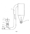
- Fig. 1 in the attached drawings shows exemplary known jet dryers using a gaseous drying agent, particularly overheated steam of a temperature up to 400°C.
- organic plant material particularly comminuted tobacco material 1
- a dosing and flow adjusting device 4 wherefrom, after the processing, the material is led out through a feeding and flow adjusting device 10.
- the term expanding is understood here as increasing the specific volume of the processed material, measured in m 3 /g.
- a side effect of known methods for processing and feeding (transporting) organic plant materials, particularly tobacco materials, to the zone of a direct processing, i.e., the expanding and/or drying zone, is inter alia creation of undesired layer of surface moisture (water), notbound chemically, which will not be able to be absorbed into the cellular structure of the tobacco material before feeding it into the expanding and/or drying zone of access.
- This layer constitutes a thermal insulation of varied thickness, which significantly hinders or even prevents the processing of the comminuted organic plant material, particularly tobacco material in any form, to be carried out in a homogenous, optimal in terms of quality, and watt-hour efficient manner.
- the comparison of the thermal conductivities, ⁇ confirms that the water layer acts as a disadvantageous and very efficient thermal insulator, i.e., a surface water layer of thickness of 1 mm stores as much thermal energy as a copper layer of thickness of about 600 mm (for the above mentioned data 665 times more).
- the present invention relates to a method of increasing efficiency of the expanding and drying process of organic plant materials, particularly in a jet dryer, used to for comminuted organic plant materials, particularly comminuted tobacco materials.
- This dryer works with the use of a gaseous expanding and/or drying agent under a working absolute pressure of 2.5 kPa to 10 Mpa.
- overheated steam is used as the gaseous expanding and/or drying process medium.
- the object of the invention consists in that during transporting the material from the feeding zone to the zone of the contact with the expanding and/or drying agent a feeder, preferably a rotary vane feeder, is flushed with a gaseous medium, preferably in a continuous manner, which is able to absorb moisture, under a working absolute pressure in the range from 2.5 kPa to 10 Mpa.
- the temperature of the gaseous medium preferably air, ranges from 50 to 200°C. Then, the residue of the process gas is removed from the rotary vane feeder.
- the transported material is heated up by the direct contact with the stream of the gaseous medium and residual surface moisture is removed from the surface of the material, the transported material being saturated with the use of the gaseous medium stream and the material is defibered.
- this invention relates to a feeder for increasing efficiency of the expanding and drying process of organic plant materials, particularly in a jet dryer used for comminuted organic plant materials, particularly comminuted tobacco.
- the feeder has vanes rotating in a housing.
- This invention is based on the idea that openings are made in the housing of the feeder for delivering the gaseous medium into the moving spaces between vanes as well as openings leading out the gaseous medium from the moving spaces between the vanes, the openings being arranged correspondingly in the walls of the housing of the feeder.
- the openings are oblong and are arranged radially with longitudinal axes being perpendicular to the axis of the inlet and outlet of the product, some of them being radially shifted relative to each other.
- the feeder according to the invention is equipped with deflectors of the material stream.
- the solution according to the invention assures the uniformity and continuity of the processes whereby optimally high expanding and drying effect is obtained to the desired level.
- Experts in the field of tobacco processing estimate this level to be in the range of 10 - 14% of humidity.
- an inlet rotary valve is employed in a form of a rotary vane feeder 4, which is located between the feeding zone 6 and the expanding and/or drying zone, i.e., the processing zone 9.
- a rotary vane feeder 4 Through the rotary vane feeder 4 the organic plant material, particularly tobacco material 1, 1A, is fed to the processing zone 9 in a manner, which eliminates or significantly reduces entering a moist gaseous medium PG to the feeding zone 6 of the organic plant material, particularly tobacco material 1.
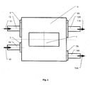
- Fig. 2 presents a cross-section of the feeder 4 which doses the organic plant material, particularly tobacco material 1, 1A to the processing zone 9.
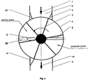
- a standard (typical) rotary valve has been modified by forming two zones, an active one and a passive one, which are shown in Fig. 4 .
- the active zone the comminuted organic plant material, particularly tobacco 1, is transported to the processing zone 9.
- the passive (return) zone only the gaseous process medium PG is transported between the vanes of the valve.
- the rotating vanes 3 form, with contact with the housing of the feeder 4, closed, moving spaces, to which a stream of the gaseous process medium is delivered via openings 5 and/or 7, which is then removed via openings 5A, 7A, the gaseous medium being for example hot air of a temperature from 50 to 150°C, under an absolute pressure in the range from 2.5 kPa to 1 MPa.
- the feeder 4 is equipped with feeding channels 13, 14 feeding the stream of the gaseous process medium to the openings 5, 5A as well as channels 13A, 14A leading out the stream of the gaseous process medium.
- openings 7 and 7A may be shifted along the radius, as shown in Fig. 2 and Fig. 3 , which lengthens the path of the gas stream in the flushed space.
- the passive zone where only gas PG is transported between vanes 3 and there is no material, particularly tobacco material 1, 1A, one may apply another shape and arrangement of the openings 5 and 5A, which do not need to be shifted relative to each other, as shown in Figs. 2 and 3 .
- Openings 5 and 7 delivering the gaseous process medium 11 and/or 12 into the housing of the feeder 4 as well as openings 5A and 7A leading out the gaseous process medium 11A and 12A are in the described embodiment oblong openings arranged radially and perpendicularly to the inlet-outlet direction of the material 1-1A fed for expanding and/or drying processing, as shown in Figs. 2 and 4 .
- material stream deflectors 2, 2A and 8 are employed, shown in Fig. 2 . Additionally, these deflectors advantageously lengthen the path of the contact between the vanes 3 and the housing of the feeder 4, which advantageously extends the duration of processing with the gaseous medium 11, 11A. Simultaneously, as shown in Fig. 4 , the deflectors eliminate the adverse phenomenon of entering (leakage) the gaseous medium, being delivered to the feeder 4, into the processing zone 9 as well as the feeding zone 6.
- the material 1A leaving the feeder 4 stops occupying the space between the vanes 3 and the housing of the feeder 4, in the processing zone 9, in which the material contacts directly the expanding and/or drying agent PG, the space being immediately filled up with the expanding and/or drying agent PG present in the processing zone 9.
- the agent is transported between the vanes 3 and the housing of the feeder 4.
- openings 5 and 7 are formed, as it is shown in Figs 2 and 3 , through which the gaseous process agent 11 and/or 12, for example ambient air, is fed to the feeder, as well as openings 5A and 7A, through which the gaseous mixture 11A and 12A is lead out (sucked off).
- the medium being a carrier of moisture, particularly water vapour.
- the absence of the moisture saturated in the feeding zone 6 of the material 1 to the feeder 4 reduces or even eliminates the condensation of the water vapour (moisture) onto the organic plant material, particularly tobacco material, fed for the processing.
- the material, without the contact with a moist gaseous agent, particularly steam, may be advantageously subjected to the influence of hot dry air (streams 11, 12 in Fig. 3 ), whereby the temperature (internal energy) of the organic plant material, particularly tobacco material, fed for the processing, increases, simultaneously allowing for the removal of the residual layer of the surface moisture, remained after the previous processing, without creating any additional disadvantageous layer of surface moisture.
- the material fed for the processing is defibred (deagglomerated), whereby the uniformity of the expanding and/or drying process of individual particles of the material is increased significantly. Also, the expenditure of energy is reduced significantly due to this solution, by eliminating a portion of energy necessary for removing the useless surface moisture, i.e., the efficiency of the process is increased.
- the gaseous medium PG is sucked off via the opening 5A and the channel 13A, taken between the vanes 3 of the feeder 4 from the processing zone 9.
- the processing gas PG is removed from the feeder 4 via the opening 5A situated radially, as shown in Fig. 3 , by the gas 11 delivered from outside, preferably air taken from the environment, delivered through the channel 13 and the opening 5, and then removed via the opening 5A and the channel 13A for optional further processing outside the feeder 4, for example for recovering thermal energy (enthalpy) from the waste stream of gas 11A.
Landscapes
- Engineering & Computer Science (AREA)
- Mechanical Engineering (AREA)
- General Engineering & Computer Science (AREA)
- Drying Of Solid Materials (AREA)
- Manufacture Of Tobacco Products (AREA)
Abstract
Description
- This invention relates to a method and a feeder for increasing efficiency of the expanding and drying process of organic plant materials, particularly a jet drier, used particularly to dry comminuted tobacco materials.
Many methods are known in the art for expanding and drying comminuted organic plant materials, as well as many technological systems having dryers, particularly jet dryers, employing a gaseous drying agent, particularly overheated steam of a temperature in the range up to 400°C. These systems comprise rotating valves operating as valves dosing comminuted products, particularly fluids.
In order to guarantee the continuity of feeding the processed organic plant material, particularly comminuted tobacco material in any form, according to a known method, the material is fed gravitationally to the expanding and/or drying zone, as shown for example inUS 6185843 . However, this known method has practical limitations resulting from a possibility of blocking and jamming the fed material, particularly tobacco material in the outlet zone, resulting in nonuniformity of the material stream fed for processing. Additionally, this solution makes it difficult or practically makes it impossible to carry out a steam, flows in the drying channel under a pressure higher than the atmospheric pressure, causing losses (leakage) of the gaseous medium, for example air, carbon dioxide (CO2), or steam, through the fed layer of the organic material, particularly tobacco material, and condensation of water vapour on the material, moistening the material fed for drying. - Another solution related to feeding organic plant materials, particularly tobacco materials, to the expanding zone is presented in
US 4791942 , where a modified rotating valve is presented, to which a process medium is fed under a pressure, and in which the process of tobacco pressure expanding is carried out employing steam and carbon dioxide. - Still another solutions are presented in
US 6158441 ,US 6581608 , andUS 6779527 , where just before feeding to the expanding and/or drying zone the processed material is conditioned by injection (adding) water and/or water vapour within the inlet valve assembly. The fluid added in this manner gives out its enthalpy (energy) of vapourizing partially to the material fed from outside, heating it up and condensating onto its surface. Due to high dynamics of the feeding process of the organic plant material to the expanding and/or drying device, the condensate layer on the material surface is not absorbed into the cellular structure of the material and stays on its surface being a useless insulator against the thermal energy until the direct contact with the expanding and/or drying medium. -
Fig. 1 in the attached drawings shows exemplary known jet dryers using a gaseous drying agent, particularly overheated steam of a temperature up to 400°C. According to this solution organic plant material, particularly comminutedtobacco material 1, is fed from the production line to the expanding and/or dryingzone 9 through a dosing andflow adjusting device 4, wherefrom, after the processing, the material is led out through a feeding andflow adjusting device 10. The term expanding is understood here as increasing the specific volume of the processed material, measured in m3/g. - A side effect of known methods for processing and feeding (transporting) organic plant materials, particularly tobacco materials, to the zone of a direct processing, i.e., the expanding and/or drying zone, is inter alia creation of undesired layer of surface moisture (water), notbound chemically, which will not be able to be absorbed into the cellular structure of the tobacco material before feeding it into the expanding and/or drying zone of access. This layer constitutes a thermal insulation of varied thickness, which significantly hinders or even prevents the processing of the comminuted organic plant material, particularly tobacco material in any form, to be carried out in a homogenous, optimal in terms of quality, and watt-hour efficient manner.
- To illustrate how an effective thermal insulator the moisture (water) can be, we will compare two coefficients defining thermal properties of two different materials, i.e., for water (thermal insulator) and for example copper (very good thermal conductor).
Water (thermal insulator) Copper (thermal conductor) Specific heat, cp [kJ/kg·K] 4.18 0.389 Thermal conductivity, λ [W/m·K] 0.58 386 - Additionally, one has to take into consideration that the necessity of vapourizing the surface moisture imposes the necessity of delivering an extra, significant amount of thermal energy to cause the phase change of liquid into vapour. However, the result o such phase change is taking a significant amount of thermal energy from the material, so called vaporization enthalpy, which for water is about 2250 kJ/kg, this in turn causing an undesired effect of cooling (instead of heating) the material.
- Considering the above issues, it would be advantageous to guarantee that the material fed to the dryer, particularly the jet dryer of the "filash" type, is free of surface moisture, which is an insulator for the thermal energy and makes it necessary to increase the time of the product staying in the drying channel and, as a consequence, to increase the dimensions of the dryer as well as the demand for energy.
- The present invention relates to a method of increasing efficiency of the expanding and drying process of organic plant materials, particularly in a jet dryer, used to for comminuted organic plant materials, particularly comminuted tobacco materials. This dryer works with the use of a gaseous expanding and/or drying agent under a working absolute pressure of 2.5 kPa to 10 Mpa. Preferably, overheated steam is used as the gaseous expanding and/or drying process medium.
- The object of the invention consists in that during transporting the material from the feeding zone to the zone of the contact with the expanding and/or drying agent a feeder, preferably a rotary vane feeder, is flushed with a gaseous medium, preferably in a continuous manner, which is able to absorb moisture, under a working absolute pressure in the range from 2.5 kPa to 10 Mpa. The temperature of the gaseous medium, preferably air, ranges from 50 to 200°C. Then, the residue of the process gas is removed from the rotary vane feeder.
- Preferably, according to the invention the transported material is heated up by the direct contact with the stream of the gaseous medium and residual surface moisture is removed from the surface of the material, the transported material being saturated with the use of the gaseous medium stream and the material is defibered.
- Also, this invention relates to a feeder for increasing efficiency of the expanding and drying process of organic plant materials, particularly in a jet dryer used for comminuted organic plant materials, particularly comminuted tobacco. The feeder has vanes rotating in a housing.
- This invention is based on the idea that openings are made in the housing of the feeder for delivering the gaseous medium into the moving spaces between vanes as well as openings leading out the gaseous medium from the moving spaces between the vanes, the openings being arranged correspondingly in the walls of the housing of the feeder. The openings are oblong and are arranged radially with longitudinal axes being perpendicular to the axis of the inlet and outlet of the product, some of them being radially shifted relative to each other. The feeder according to the invention is equipped with deflectors of the material stream.
- The solution according to the invention assures the uniformity and continuity of the processes whereby optimally high expanding and drying effect is obtained to the desired level. Experts in the field of tobacco processing estimate this level to be in the range of 10 - 14% of humidity.
- The invention is illustrated by an embodiment shown in the accompanying drawings, in which:
-
Fig. 1 shows schematically a known device for expanding and/or drying comminuted organic plant materials, particularly tobacco materials, comprising a feeding and flow adjusting device; -
Fig. 2 shows a cross-sectional view of an inlet feeder according to the invention; -
Fig. 3 shows a plan view of the feeder ofFig. 2 with the channels delivering the process medium to this valve and the channels leading out the process medium from this valve; -
Fig. 4 shows a cross-sectional view of a feeder according to the invention in a working position of the driver vanes of the feeder, in which the operating range of the delivered gaseous medium within the feeder is shown. - According to the invention, in the device for expanding and/or drying comminuted tobacco material an inlet rotary valve is employed in a form of a
rotary vane feeder 4, which is located between thefeeding zone 6 and the expanding and/or drying zone, i.e., theprocessing zone 9. Through therotary vane feeder 4 the organic plant material, particularlytobacco material processing zone 9 in a manner, which eliminates or significantly reduces entering a moist gaseous medium PG to thefeeding zone 6 of the organic plant material, particularlytobacco material 1. -
Fig. 2 presents a cross-section of thefeeder 4 which doses the organic plant material, particularlytobacco material processing zone 9. A standard (typical) rotary valve has been modified by forming two zones, an active one and a passive one, which are shown inFig. 4 . In the active zone the comminuted organic plant material, particularlytobacco 1, is transported to theprocessing zone 9. In the passive (return) zone only the gaseous process medium PG is transported between the vanes of the valve. - The rotating
vanes 3 form, with contact with the housing of thefeeder 4, closed, moving spaces, to which a stream of the gaseous process medium is delivered viaopenings 5 and/or 7, which is then removed viaopenings - As shown in
Fig. 3 , thefeeder 4 is equipped withfeeding channels openings channels - In order to intensify the effect of flushing the spaces between the
vanes 3 with the gas,openings Fig. 2 andFig. 3 , which lengthens the path of the gas stream in the flushed space. In the passive zone, where only gas PG is transported betweenvanes 3 and there is no material, particularlytobacco material openings Figs. 2 and3 . -
Openings gaseous process medium 11 and/or 12 into the housing of thefeeder 4 as well asopenings gaseous process medium Figs. 2 and4 . - For obtaining optimal and advantageous use of the working spaces of the valve, i.e., spaces between the driver vanes 3 and the housing of the
feeder 4,material stream deflectors Fig. 2 . Additionally, these deflectors advantageously lengthen the path of the contact between thevanes 3 and the housing of thefeeder 4, which advantageously extends the duration of processing with thegaseous medium Fig. 4 , the deflectors eliminate the adverse phenomenon of entering (leakage) the gaseous medium, being delivered to thefeeder 4, into theprocessing zone 9 as well as thefeeding zone 6. - The
material 1A leaving thefeeder 4 stops occupying the space between thevanes 3 and the housing of thefeeder 4, in theprocessing zone 9, in which the material contacts directly the expanding and/or drying agent PG, the space being immediately filled up with the expanding and/or drying agent PG present in theprocessing zone 9. Next, the agent is transported between thevanes 3 and the housing of thefeeder 4. In thiszone openings Figs 2 and3 , through which thegaseous process agent 11 and/or 12, for example ambient air, is fed to the feeder, as well asopenings gaseous mixture - As a result of using the above solution in the moment of reopening the rotating working chamber of the
feeder 4 no residues of moist gaseous agent PG enter thefeeding zone 6, and as a consequence no condensation of moisture occurs on the organic plant material, particularlytobacco material 1, fed to the processing. The organic plant material, particularlytobacco material 1, fed, according to this method, for the expanding and/or drying does not have an insulating layer of free, chemically unbound surface moisture, which is a thermal insulator and an inhibitor for chemical reactions occurring within theprocessing zone 9, which allows for significant reduction of amount of energy delivered from outside necessary for obtaining an appropriate expanding and/or drying process. - As a result of the employed solution entire or significant amount of the gaseous process medium PG is removed from the
feeder 4 feeding thematerial 1 and separating from theprocessing zone 9, the medium being a carrier of moisture, particularly water vapour. The absence of the moisture saturated in thefeeding zone 6 of thematerial 1 to thefeeder 4 reduces or even eliminates the condensation of the water vapour (moisture) onto the organic plant material, particularly tobacco material, fed for the processing. The material, without the contact with a moist gaseous agent, particularly steam, may be advantageously subjected to the influence of hot dry air (streams Fig. 3 ), whereby the temperature (internal energy) of the organic plant material, particularly tobacco material, fed for the processing, increases, simultaneously allowing for the removal of the residual layer of the surface moisture, remained after the previous processing, without creating any additional disadvantageous layer of surface moisture. - Due to the contact between the comminuted, usually fibrous and swirled organic plant material, particularly tobacco material, fed for the processing and the stream of the
gaseous medium - Furthermore, the gaseous medium PG is sucked off via the opening 5A and the
channel 13A, taken between thevanes 3 of thefeeder 4 from theprocessing zone 9. The processing gas PG is removed from thefeeder 4 via theopening 5A situated radially, as shown inFig. 3 , by thegas 11 delivered from outside, preferably air taken from the environment, delivered through thechannel 13 and theopening 5, and then removed via theopening 5A and thechannel 13A for optional further processing outside thefeeder 4, for example for recovering thermal energy (enthalpy) from the waste stream ofgas 11A. As a consequence, obtaining these effects allows for shorter staying of the organic plant materials, particularly tobacco materials, within the expanding and/or drying zone, and this in turn allows for the reduction of the dimensions of the drying channels and the whole jet dryer. Moreover, one gains a significant increase of the watt-hour efficiency of the expanding and/or drying process of organic plant materials, particularly tobacco materials.
Claims (8)
- A method of increasing the efficiency of the expanding and drying process of organic plant materials, particularly in a jet dryer used for comminuted organic plant materials, particularly comminuted tobacco materials, working with the use of a gaseous expanding and/or drying agent under a working absolute pressure in the range from 2.5 kPa to 10 MPa, the gaseous processing expanding and/or drying agent being preferably overheated steam, characterized in that, during transporting the material (1) from the feeding zone (6) to the zone (9) of contact with the expanding and/or drying agent, a feeder, preferably a rotary vane feeder (4) is flushed, preferably in a continuos manner, with a gaseous medium (11, 12), which is capable of absorbing moisture, under an absolute pressure in the range from 2.5 kPa to 10 MPa, the temperature of the gaseous medium (11, 12) being preferably in the range from 50 to 200°C, and residues of the processing gas are removed from the rotary vane feeder (4).
- A method according to claim 1, characterized in that the transported material (1) is heated up in the direct contact with the stream of the gaseous medium (11, 12), and residues of the surface moisture are removed from the surface of the material (1).
- A method according to claim 1 characterized in that the transported material (1) is saturated by means of the stream of the gaseous medium (11, 12).
- A method according to claim 1 or 3 characterized in that defibering process of the material (1) is carried out by means of the stream of the gaseous medium (11, 12).
- A feeder for increasing the efficiency of the expanding and drying process of organic plant materials, particularly in a jet dryer used for comminuted organic plant materials, particularly comminuted tobacco materials, having vanes rotating within a housing, characterized in that openings (5, 7) are formed in the housing of the feeder (4), delivering a gaseous medium to the moving spaces between vanes (3) as well as openings (5A, 7A) leading out the gaseous medium from the moving spaces between the vanes (3), the openings (5, 7, 5A, 7A) being arranged respectively in the walls of the housing of the feeder (4).
- A feeder according to claim 5 characterized in that the openings (5, 7) as well as the openings (5A, 7A) are oblong and are arranged radially, and their longitudinal axes are perpendicular to the inlet and outlet axis of the material (1).
- A feeder according to claim 5 or 6 characterized in that the openings (7) as well as the openings (7A) are radially shifted relative to each other.
- A feeder according to claim 5 characterized in that it is equipped with deflectors (2, 8) of the stream of the material.
Applications Claiming Priority (1)
| Application Number | Priority Date | Filing Date | Title |
|---|---|---|---|
| PL383413A PL211482B1 (en) | 2007-09-24 | 2007-09-24 | The manner and dosing unit for increasing of efficiency of the swelling process and drying of organic materials, especially in stream dryer |
Publications (2)
| Publication Number | Publication Date |
|---|---|
| EP2042045A1 true EP2042045A1 (en) | 2009-04-01 |
| EP2042045B1 EP2042045B1 (en) | 2012-12-05 |
Family
ID=40245850
Family Applications (1)
| Application Number | Title | Priority Date | Filing Date |
|---|---|---|---|
| EP08164389A Not-in-force EP2042045B1 (en) | 2007-09-24 | 2008-09-16 | Method and feeder for increasing efficiency of the expanding and drying process of organic plant materials, particularly in a jet drier and a feeder for use in the method |
Country Status (5)
| Country | Link |
|---|---|
| US (1) | US20090090374A1 (en) |
| EP (1) | EP2042045B1 (en) |
| JP (1) | JP5355011B2 (en) |
| CN (1) | CN101396168B (en) |
| PL (1) | PL211482B1 (en) |
Cited By (1)
| Publication number | Priority date | Publication date | Assignee | Title |
|---|---|---|---|---|
| ITTV20110009A1 (en) * | 2011-01-27 | 2012-07-28 | Garbuio Spa | TOBACCO COOLING DEVICE, PARTICULARLY FOR A TOBACCO DRYING SYSTEM. |
Families Citing this family (7)
| Publication number | Priority date | Publication date | Assignee | Title |
|---|---|---|---|---|
| CN102679700A (en) * | 2012-05-16 | 2012-09-19 | 江苏诚信制药有限公司 | L-Alanyl-L-Glutamine preparation process improvement system |
| RU2562780C1 (en) * | 2014-08-19 | 2015-09-10 | Федеральное государственное бюджетное научное учреждение "Всероссийский научно-исследовательский институт табака, махорки и табачных изделий" (ФГБНУ ВНИИТТИ) | Installation for tobacco leaves drying |
| CN104528291B (en) * | 2014-12-27 | 2016-12-21 | 蚌埠玻璃工业设计研究院 | A kind of rotating blanking valve |
| KR101718394B1 (en) | 2016-01-18 | 2017-03-22 | 주식회사 다산피앤지 | Light-weight panel frame |
| CN106839753B (en) * | 2016-12-30 | 2018-10-30 | 山东中烟工业有限责任公司 | A kind of guide cover structure suitable for pneumatic convey drier charging gas lock |
| DE102017120626A1 (en) * | 2017-09-07 | 2019-03-07 | Hauni Maschinenbau Gmbh | Conditioning of tobacco |
| CN115486552B (en) * | 2022-11-07 | 2024-01-19 | 云南中烟工业有限责任公司 | Rotary vacuum conditioning equipment and conditioning method for tobacco materials |
Citations (8)
| Publication number | Priority date | Publication date | Assignee | Title |
|---|---|---|---|---|
| GB2147982A (en) * | 1983-10-13 | 1985-05-22 | Brown & Williamson Tobacco Corp | Pneumatic tobacco conveying and treating apparatus |
| US4791942A (en) | 1986-08-01 | 1988-12-20 | The American Tobacco Company | Process and apparatus for the expansion of tobacco |
| US6158441A (en) | 1997-08-08 | 2000-12-12 | Hauni Maschinenbau Ag | Method of and apparatus for applying a conditioning agent to tobacco |
| US6185843B1 (en) | 1997-03-27 | 2001-02-13 | British American Tobacco (Investments) Limited | Tobacco dryers |
| US6779527B2 (en) | 2000-08-04 | 2004-08-24 | British American Tobacco (Germany) Gmbh | Device for conditioning comminuted tobacco material |
| EP1586245A1 (en) * | 2004-04-15 | 2005-10-19 | Hauni Primary GmbH | Transporting device for a machine of the tobacco industry |
| GB2426566A (en) * | 2005-05-25 | 2006-11-29 | Hauni Maschinenbau Ag | Tobacco dryer comprising a closed processing chamber formed by starwheel airlocks |
| WO2007134879A1 (en) * | 2006-05-23 | 2007-11-29 | Hauni Maschinenbau Ag | Flash dryer for drying a fibrous tobacco product |
Family Cites Families (7)
| Publication number | Priority date | Publication date | Assignee | Title |
|---|---|---|---|---|
| US3043736A (en) * | 1959-03-02 | 1962-07-10 | Eastman Kodak Co | Method for making additive filters |
| US3347247A (en) * | 1964-05-14 | 1967-10-17 | Philip Morris Inc | Tobacco smoke filter |
| JP3140039B2 (en) * | 1990-11-07 | 2001-03-05 | 日本たばこ産業株式会社 | Flash drying method and apparatus for tobacco raw materials |
| US6032384A (en) * | 1998-03-26 | 2000-03-07 | Heartland Forage, Inc. | Method of drying moist organic material |
| CN1219470C (en) * | 2003-12-29 | 2005-09-21 | 江苏智思机械制造有限公司 | New Process for producing tobacco shred |
| DE102006023259A1 (en) * | 2006-05-18 | 2007-11-22 | Alzchem Hart Gmbh | Use of residual and / or waste materials in electric low-shaft kilns |
| PL211481B1 (en) * | 2007-05-30 | 2012-05-31 | Int Tobacco Machinery Poland | The manner of increase of efficiency of dryer, especially stream dryer |
-
2007
- 2007-09-24 PL PL383413A patent/PL211482B1/en not_active IP Right Cessation
-
2008
- 2008-09-12 US US12/209,673 patent/US20090090374A1/en not_active Abandoned
- 2008-09-16 EP EP08164389A patent/EP2042045B1/en not_active Not-in-force
- 2008-09-23 CN CN200810165760.2A patent/CN101396168B/en not_active Expired - Fee Related
- 2008-09-24 JP JP2008244313A patent/JP5355011B2/en not_active Expired - Fee Related
Patent Citations (9)
| Publication number | Priority date | Publication date | Assignee | Title |
|---|---|---|---|---|
| GB2147982A (en) * | 1983-10-13 | 1985-05-22 | Brown & Williamson Tobacco Corp | Pneumatic tobacco conveying and treating apparatus |
| US4791942A (en) | 1986-08-01 | 1988-12-20 | The American Tobacco Company | Process and apparatus for the expansion of tobacco |
| US6185843B1 (en) | 1997-03-27 | 2001-02-13 | British American Tobacco (Investments) Limited | Tobacco dryers |
| US6158441A (en) | 1997-08-08 | 2000-12-12 | Hauni Maschinenbau Ag | Method of and apparatus for applying a conditioning agent to tobacco |
| US6581608B1 (en) | 1997-08-08 | 2003-06-24 | Hauni Maschinenbau Ag | Apparatus for applying conditioning agent to tobacco |
| US6779527B2 (en) | 2000-08-04 | 2004-08-24 | British American Tobacco (Germany) Gmbh | Device for conditioning comminuted tobacco material |
| EP1586245A1 (en) * | 2004-04-15 | 2005-10-19 | Hauni Primary GmbH | Transporting device for a machine of the tobacco industry |
| GB2426566A (en) * | 2005-05-25 | 2006-11-29 | Hauni Maschinenbau Ag | Tobacco dryer comprising a closed processing chamber formed by starwheel airlocks |
| WO2007134879A1 (en) * | 2006-05-23 | 2007-11-29 | Hauni Maschinenbau Ag | Flash dryer for drying a fibrous tobacco product |
Cited By (4)
| Publication number | Priority date | Publication date | Assignee | Title |
|---|---|---|---|---|
| ITTV20110009A1 (en) * | 2011-01-27 | 2012-07-28 | Garbuio Spa | TOBACCO COOLING DEVICE, PARTICULARLY FOR A TOBACCO DRYING SYSTEM. |
| CN102613682A (en) * | 2011-01-27 | 2012-08-01 | 加布伊奥股份公司 | Tobacco cooling device, particularly for a tobacco drying system |
| EP2481301A1 (en) * | 2011-01-27 | 2012-08-01 | GARBUIO S.p.A. | Tobacco cooling device, particularly for a tobacco drying system |
| CN102613682B (en) * | 2011-01-27 | 2015-12-16 | 加布伊奥股份公司 | For the tobacco cooling device of Tobacco drying system |
Also Published As
| Publication number | Publication date |
|---|---|
| CN101396168A (en) | 2009-04-01 |
| PL211482B1 (en) | 2012-05-31 |
| EP2042045B1 (en) | 2012-12-05 |
| JP2009159944A (en) | 2009-07-23 |
| JP5355011B2 (en) | 2013-11-27 |
| CN101396168B (en) | 2013-03-13 |
| PL383413A1 (en) | 2009-03-30 |
| US20090090374A1 (en) | 2009-04-09 |
Similar Documents
| Publication | Publication Date | Title |
|---|---|---|
| EP2042045B1 (en) | Method and feeder for increasing efficiency of the expanding and drying process of organic plant materials, particularly in a jet drier and a feeder for use in the method | |
| US10533799B2 (en) | System and method of removing moisture from fibrous or porous materials using microwave radiation and RF energy | |
| JP5420682B2 (en) | Wood drying method and unit for carrying out the method | |
| CN109937188B (en) | Production method of lithium hydroxide anhydrate and rotary furnace used in the production method | |
| KR20120069696A (en) | Particle pump methods and devices | |
| US20070256316A1 (en) | Indirect-heat thermal processing of particulate material | |
| US20120260518A1 (en) | Dryer | |
| ES2362943T3 (en) | PROCEDURE AND DEVICE FOR THE MANUFACTURE AND / OR CONDITIONING OF POWDERED MATERIAL. | |
| US7401417B2 (en) | Method and a device for drying or heat treatment of a web-formed material | |
| CN112534199A (en) | Drying apparatus for wet substrates and related drying method for wet substrates | |
| JP5490499B2 (en) | Single plate drying aid | |
| GB2426566A (en) | Tobacco dryer comprising a closed processing chamber formed by starwheel airlocks | |
| CN206955893U (en) | The sludge mesh dryer of bilayer charging | |
| JPH02216292A (en) | Steam box and humidity regulator of sheet member | |
| AU8111794A (en) | Treatment of hygroscopic material | |
| EP2952105B1 (en) | Expanding method of tobacco raw material and expanding system of the same | |
| KR20190132649A (en) | Apparatus and Method for Reducing H2O-Partial Pressure in OVPD-Coated Devices | |
| KR20000069390A (en) | Method of and apparatus for drying a fiber web | |
| CN115447957B (en) | Feeding and conveying device and equipment for hygroscopic raw materials for printed circuit board chemicals | |
| US20200208352A1 (en) | Method and Device for Applying a Material to a Moving Web | |
| CN220803672U (en) | Zirconia smashing device with hot air flow auxiliary effect | |
| KR20150022136A (en) | Low rank coal pulverizing system | |
| FI20220002A1 (en) | Method for processing moist materials | |
| FI71367C (en) | PROOF OF EFFECTIVE EFFECTIVENESS WITH AVIABILITY AND ENTRY MACHINERY | |
| KR101217541B1 (en) | Dual Air-Knife Injection device for uniform drying of a glass panel |
Legal Events
| Date | Code | Title | Description |
|---|---|---|---|
| PUAI | Public reference made under article 153(3) epc to a published international application that has entered the european phase |
Free format text: ORIGINAL CODE: 0009012 |
|
| AK | Designated contracting states |
Kind code of ref document: A1 Designated state(s): AT BE BG CH CY CZ DE DK EE ES FI FR GB GR HR HU IE IS IT LI LT LU LV MC MT NL NO PL PT RO SE SI SK TR |
|
| AX | Request for extension of the european patent |
Extension state: AL BA MK RS |
|
| 17P | Request for examination filed |
Effective date: 20091001 |
|
| 17Q | First examination report despatched |
Effective date: 20091027 |
|
| AKX | Designation fees paid |
Designated state(s): AT BE BG CH CY CZ DE DK EE ES FI FR GB GR HR HU IE IS IT LI LT LU LV MC MT NL NO PL PT RO SE SI SK TR |
|
| RAP1 | Party data changed (applicant data changed or rights of an application transferred) |
Owner name: INTERNATIONAL TOBACCO MACHINERY POLAND SP. Z O.O. |
|
| GRAP | Despatch of communication of intention to grant a patent |
Free format text: ORIGINAL CODE: EPIDOSNIGR1 |
|
| RIN1 | Information on inventor provided before grant (corrected) |
Inventor name: DRUZDZEL, ARKADIUSZ |
|
| GRAS | Grant fee paid |
Free format text: ORIGINAL CODE: EPIDOSNIGR3 |
|
| GRAA | (expected) grant |
Free format text: ORIGINAL CODE: 0009210 |
|
| AK | Designated contracting states |
Kind code of ref document: B1 Designated state(s): AT BE BG CH CY CZ DE DK EE ES FI FR GB GR HR HU IE IS IT LI LT LU LV MC MT NL NO PL PT RO SE SI SK TR |
|
| REG | Reference to a national code |
Ref country code: GB Ref legal event code: FG4D |
|
| REG | Reference to a national code |
Ref country code: CH Ref legal event code: EP |
|
| REG | Reference to a national code |
Ref country code: AT Ref legal event code: REF Ref document number: 586773 Country of ref document: AT Kind code of ref document: T Effective date: 20121215 |
|
| REG | Reference to a national code |
Ref country code: IE Ref legal event code: FG4D |
|
| REG | Reference to a national code |
Ref country code: DE Ref legal event code: R096 Ref document number: 602008020566 Country of ref document: DE Effective date: 20130131 |
|
| REG | Reference to a national code |
Ref country code: CH Ref legal event code: NV Representative=s name: ARNOLD AND SIEDSMA AG, CH |
|
| REG | Reference to a national code |
Ref country code: AT Ref legal event code: MK05 Ref document number: 586773 Country of ref document: AT Kind code of ref document: T Effective date: 20121205 |
|
| PG25 | Lapsed in a contracting state [announced via postgrant information from national office to epo] |
Ref country code: LT Free format text: LAPSE BECAUSE OF FAILURE TO SUBMIT A TRANSLATION OF THE DESCRIPTION OR TO PAY THE FEE WITHIN THE PRESCRIBED TIME-LIMIT Effective date: 20121205 Ref country code: ES Free format text: LAPSE BECAUSE OF FAILURE TO SUBMIT A TRANSLATION OF THE DESCRIPTION OR TO PAY THE FEE WITHIN THE PRESCRIBED TIME-LIMIT Effective date: 20130316 Ref country code: FI Free format text: LAPSE BECAUSE OF FAILURE TO SUBMIT A TRANSLATION OF THE DESCRIPTION OR TO PAY THE FEE WITHIN THE PRESCRIBED TIME-LIMIT Effective date: 20121205 Ref country code: NO Free format text: LAPSE BECAUSE OF FAILURE TO SUBMIT A TRANSLATION OF THE DESCRIPTION OR TO PAY THE FEE WITHIN THE PRESCRIBED TIME-LIMIT Effective date: 20130305 Ref country code: SE Free format text: LAPSE BECAUSE OF FAILURE TO SUBMIT A TRANSLATION OF THE DESCRIPTION OR TO PAY THE FEE WITHIN THE PRESCRIBED TIME-LIMIT Effective date: 20121205 |
|
| REG | Reference to a national code |
Ref country code: NL Ref legal event code: VDEP Effective date: 20121205 |
|
| REG | Reference to a national code |
Ref country code: LT Ref legal event code: MG4D |
|
| PG25 | Lapsed in a contracting state [announced via postgrant information from national office to epo] |
Ref country code: LV Free format text: LAPSE BECAUSE OF FAILURE TO SUBMIT A TRANSLATION OF THE DESCRIPTION OR TO PAY THE FEE WITHIN THE PRESCRIBED TIME-LIMIT Effective date: 20121205 Ref country code: PL Free format text: LAPSE BECAUSE OF FAILURE TO SUBMIT A TRANSLATION OF THE DESCRIPTION OR TO PAY THE FEE WITHIN THE PRESCRIBED TIME-LIMIT Effective date: 20121205 Ref country code: GR Free format text: LAPSE BECAUSE OF FAILURE TO SUBMIT A TRANSLATION OF THE DESCRIPTION OR TO PAY THE FEE WITHIN THE PRESCRIBED TIME-LIMIT Effective date: 20130306 Ref country code: CY Free format text: LAPSE BECAUSE OF FAILURE TO SUBMIT A TRANSLATION OF THE DESCRIPTION OR TO PAY THE FEE WITHIN THE PRESCRIBED TIME-LIMIT Effective date: 20121205 Ref country code: SI Free format text: LAPSE BECAUSE OF FAILURE TO SUBMIT A TRANSLATION OF THE DESCRIPTION OR TO PAY THE FEE WITHIN THE PRESCRIBED TIME-LIMIT Effective date: 20121205 |
|
| PG25 | Lapsed in a contracting state [announced via postgrant information from national office to epo] |
Ref country code: AT Free format text: LAPSE BECAUSE OF FAILURE TO SUBMIT A TRANSLATION OF THE DESCRIPTION OR TO PAY THE FEE WITHIN THE PRESCRIBED TIME-LIMIT Effective date: 20121205 |
|
| PG25 | Lapsed in a contracting state [announced via postgrant information from national office to epo] |
Ref country code: EE Free format text: LAPSE BECAUSE OF FAILURE TO SUBMIT A TRANSLATION OF THE DESCRIPTION OR TO PAY THE FEE WITHIN THE PRESCRIBED TIME-LIMIT Effective date: 20121205 Ref country code: IS Free format text: LAPSE BECAUSE OF FAILURE TO SUBMIT A TRANSLATION OF THE DESCRIPTION OR TO PAY THE FEE WITHIN THE PRESCRIBED TIME-LIMIT Effective date: 20130405 Ref country code: CZ Free format text: LAPSE BECAUSE OF FAILURE TO SUBMIT A TRANSLATION OF THE DESCRIPTION OR TO PAY THE FEE WITHIN THE PRESCRIBED TIME-LIMIT Effective date: 20121205 Ref country code: SK Free format text: LAPSE BECAUSE OF FAILURE TO SUBMIT A TRANSLATION OF THE DESCRIPTION OR TO PAY THE FEE WITHIN THE PRESCRIBED TIME-LIMIT Effective date: 20121205 Ref country code: BE Free format text: LAPSE BECAUSE OF FAILURE TO SUBMIT A TRANSLATION OF THE DESCRIPTION OR TO PAY THE FEE WITHIN THE PRESCRIBED TIME-LIMIT Effective date: 20121205 |
|
| PG25 | Lapsed in a contracting state [announced via postgrant information from national office to epo] |
Ref country code: NL Free format text: LAPSE BECAUSE OF FAILURE TO SUBMIT A TRANSLATION OF THE DESCRIPTION OR TO PAY THE FEE WITHIN THE PRESCRIBED TIME-LIMIT Effective date: 20121205 Ref country code: PT Free format text: LAPSE BECAUSE OF FAILURE TO SUBMIT A TRANSLATION OF THE DESCRIPTION OR TO PAY THE FEE WITHIN THE PRESCRIBED TIME-LIMIT Effective date: 20130405 Ref country code: RO Free format text: LAPSE BECAUSE OF FAILURE TO SUBMIT A TRANSLATION OF THE DESCRIPTION OR TO PAY THE FEE WITHIN THE PRESCRIBED TIME-LIMIT Effective date: 20121205 |
|
| PLBE | No opposition filed within time limit |
Free format text: ORIGINAL CODE: 0009261 |
|
| STAA | Information on the status of an ep patent application or granted ep patent |
Free format text: STATUS: NO OPPOSITION FILED WITHIN TIME LIMIT |
|
| PG25 | Lapsed in a contracting state [announced via postgrant information from national office to epo] |
Ref country code: DK Free format text: LAPSE BECAUSE OF FAILURE TO SUBMIT A TRANSLATION OF THE DESCRIPTION OR TO PAY THE FEE WITHIN THE PRESCRIBED TIME-LIMIT Effective date: 20121205 |
|
| 26N | No opposition filed |
Effective date: 20130906 |
|
| REG | Reference to a national code |
Ref country code: HU Ref legal event code: AG4A Ref document number: E017298 Country of ref document: HU |
|
| REG | Reference to a national code |
Ref country code: DE Ref legal event code: R097 Ref document number: 602008020566 Country of ref document: DE Effective date: 20130906 |
|
| PG25 | Lapsed in a contracting state [announced via postgrant information from national office to epo] |
Ref country code: HR Free format text: LAPSE BECAUSE OF FAILURE TO SUBMIT A TRANSLATION OF THE DESCRIPTION OR TO PAY THE FEE WITHIN THE PRESCRIBED TIME-LIMIT Effective date: 20130731 |
|
| PG25 | Lapsed in a contracting state [announced via postgrant information from national office to epo] |
Ref country code: MC Free format text: LAPSE BECAUSE OF FAILURE TO SUBMIT A TRANSLATION OF THE DESCRIPTION OR TO PAY THE FEE WITHIN THE PRESCRIBED TIME-LIMIT Effective date: 20121205 |
|
| REG | Reference to a national code |
Ref country code: CH Ref legal event code: PL |
|
| GBPC | Gb: european patent ceased through non-payment of renewal fee |
Effective date: 20130916 |
|
| REG | Reference to a national code |
Ref country code: FR Ref legal event code: ST Effective date: 20140530 |
|
| REG | Reference to a national code |
Ref country code: IE Ref legal event code: MM4A |
|
| REG | Reference to a national code |
Ref country code: DE Ref legal event code: R119 Ref document number: 602008020566 Country of ref document: DE Effective date: 20140401 |
|
| PG25 | Lapsed in a contracting state [announced via postgrant information from national office to epo] |
Ref country code: CH Free format text: LAPSE BECAUSE OF NON-PAYMENT OF DUE FEES Effective date: 20130930 Ref country code: GB Free format text: LAPSE BECAUSE OF NON-PAYMENT OF DUE FEES Effective date: 20130916 Ref country code: IE Free format text: LAPSE BECAUSE OF NON-PAYMENT OF DUE FEES Effective date: 20130916 Ref country code: LI Free format text: LAPSE BECAUSE OF NON-PAYMENT OF DUE FEES Effective date: 20130930 |
|
| PG25 | Lapsed in a contracting state [announced via postgrant information from national office to epo] |
Ref country code: IT Free format text: LAPSE BECAUSE OF NON-PAYMENT OF DUE FEES Effective date: 20130916 Ref country code: BG Free format text: LAPSE BECAUSE OF NON-PAYMENT OF DUE FEES Effective date: 20140630 Ref country code: DE Free format text: LAPSE BECAUSE OF NON-PAYMENT OF DUE FEES Effective date: 20140401 Ref country code: FR Free format text: LAPSE BECAUSE OF NON-PAYMENT OF DUE FEES Effective date: 20130930 |
|
| PG25 | Lapsed in a contracting state [announced via postgrant information from national office to epo] |
Ref country code: BG Free format text: LAPSE BECAUSE OF NON-PAYMENT OF DUE FEES Effective date: 20130930 Ref country code: HU Free format text: LAPSE BECAUSE OF NON-PAYMENT OF DUE FEES Effective date: 20130917 |
|
| PG25 | Lapsed in a contracting state [announced via postgrant information from national office to epo] |
Ref country code: BG Free format text: LAPSE BECAUSE OF NON-PAYMENT OF DUE FEES Effective date: 20140930 |
|
| PG25 | Lapsed in a contracting state [announced via postgrant information from national office to epo] |
Ref country code: TR Free format text: LAPSE BECAUSE OF FAILURE TO SUBMIT A TRANSLATION OF THE DESCRIPTION OR TO PAY THE FEE WITHIN THE PRESCRIBED TIME-LIMIT Effective date: 20121205 Ref country code: MT Free format text: LAPSE BECAUSE OF FAILURE TO SUBMIT A TRANSLATION OF THE DESCRIPTION OR TO PAY THE FEE WITHIN THE PRESCRIBED TIME-LIMIT Effective date: 20121205 |
|
| PG25 | Lapsed in a contracting state [announced via postgrant information from national office to epo] |
Ref country code: LU Free format text: LAPSE BECAUSE OF NON-PAYMENT OF DUE FEES Effective date: 20130916 |