EP2041848B1 - Fiber optic power laser device - Google Patents
Fiber optic power laser device Download PDFInfo
- Publication number
- EP2041848B1 EP2041848B1 EP07823513.2A EP07823513A EP2041848B1 EP 2041848 B1 EP2041848 B1 EP 2041848B1 EP 07823513 A EP07823513 A EP 07823513A EP 2041848 B1 EP2041848 B1 EP 2041848B1
- Authority
- EP
- European Patent Office
- Prior art keywords
- fiber
- optical fiber
- optical
- multimode
- multimode optical
- Prior art date
- Legal status (The legal status is an assumption and is not a legal conclusion. Google has not performed a legal analysis and makes no representation as to the accuracy of the status listed.)
- Expired - Fee Related
Links
- 239000000835 fiber Substances 0.000 title claims description 136
- 230000003287 optical effect Effects 0.000 claims description 155
- 239000013307 optical fiber Substances 0.000 claims description 148
- 230000000087 stabilizing effect Effects 0.000 claims description 13
- 230000008878 coupling Effects 0.000 claims description 8
- 238000010168 coupling process Methods 0.000 claims description 8
- 238000005859 coupling reaction Methods 0.000 claims description 8
- 230000005855 radiation Effects 0.000 description 24
- 238000001914 filtration Methods 0.000 description 15
- 238000009826 distribution Methods 0.000 description 12
- 238000000034 method Methods 0.000 description 9
- 230000006641 stabilisation Effects 0.000 description 8
- 230000000694 effects Effects 0.000 description 6
- 238000004364 calculation method Methods 0.000 description 5
- 235000021183 entrée Nutrition 0.000 description 5
- 239000011521 glass Substances 0.000 description 5
- 230000010287 polarization Effects 0.000 description 5
- VYPSYNLAJGMNEJ-UHFFFAOYSA-N Silicium dioxide Chemical compound O=[Si]=O VYPSYNLAJGMNEJ-UHFFFAOYSA-N 0.000 description 4
- 229910052769 Ytterbium Inorganic materials 0.000 description 3
- 238000010521 absorption reaction Methods 0.000 description 3
- 238000004519 manufacturing process Methods 0.000 description 3
- 238000005086 pumping Methods 0.000 description 3
- -1 rare earth ion Chemical class 0.000 description 3
- 238000002310 reflectometry Methods 0.000 description 3
- 239000007787 solid Substances 0.000 description 3
- 238000011105 stabilization Methods 0.000 description 3
- 230000004927 fusion Effects 0.000 description 2
- 238000003384 imaging method Methods 0.000 description 2
- 150000002500 ions Chemical class 0.000 description 2
- 239000000463 material Substances 0.000 description 2
- 230000001902 propagating effect Effects 0.000 description 2
- 229910052761 rare earth metal Inorganic materials 0.000 description 2
- 239000000377 silicon dioxide Substances 0.000 description 2
- 239000000243 solution Substances 0.000 description 2
- NAWDYIZEMPQZHO-UHFFFAOYSA-N ytterbium Chemical compound [Yb] NAWDYIZEMPQZHO-UHFFFAOYSA-N 0.000 description 2
- PCTMTFRHKVHKIS-BMFZQQSSSA-N (1s,3r,4e,6e,8e,10e,12e,14e,16e,18s,19r,20r,21s,25r,27r,30r,31r,33s,35r,37s,38r)-3-[(2r,3s,4s,5s,6r)-4-amino-3,5-dihydroxy-6-methyloxan-2-yl]oxy-19,25,27,30,31,33,35,37-octahydroxy-18,20,21-trimethyl-23-oxo-22,39-dioxabicyclo[33.3.1]nonatriaconta-4,6,8,10 Chemical compound C1C=C2C[C@@H](OS(O)(=O)=O)CC[C@]2(C)[C@@H]2[C@@H]1[C@@H]1CC[C@H]([C@H](C)CCCC(C)C)[C@@]1(C)CC2.O[C@H]1[C@@H](N)[C@H](O)[C@@H](C)O[C@H]1O[C@H]1/C=C/C=C/C=C/C=C/C=C/C=C/C=C/[C@H](C)[C@@H](O)[C@@H](C)[C@H](C)OC(=O)C[C@H](O)C[C@H](O)CC[C@@H](O)[C@H](O)C[C@H](O)C[C@](O)(C[C@H](O)[C@H]2C(O)=O)O[C@H]2C1 PCTMTFRHKVHKIS-BMFZQQSSSA-N 0.000 description 1
- 229910052691 Erbium Inorganic materials 0.000 description 1
- 229910052779 Neodymium Inorganic materials 0.000 description 1
- 229920000297 Rayon Polymers 0.000 description 1
- 229910052775 Thulium Inorganic materials 0.000 description 1
- 241001639412 Verres Species 0.000 description 1
- 230000002745 absorbent Effects 0.000 description 1
- 239000002250 absorbent Substances 0.000 description 1
- 238000004026 adhesive bonding Methods 0.000 description 1
- 238000005452 bending Methods 0.000 description 1
- 230000005540 biological transmission Effects 0.000 description 1
- 238000003776 cleavage reaction Methods 0.000 description 1
- 239000004020 conductor Substances 0.000 description 1
- 230000007423 decrease Effects 0.000 description 1
- 230000008021 deposition Effects 0.000 description 1
- 239000002019 doping agent Substances 0.000 description 1
- 238000005516 engineering process Methods 0.000 description 1
- UYAHIZSMUZPPFV-UHFFFAOYSA-N erbium Chemical compound [Er] UYAHIZSMUZPPFV-UHFFFAOYSA-N 0.000 description 1
- 230000002349 favourable effect Effects 0.000 description 1
- 239000013305 flexible fiber Substances 0.000 description 1
- 230000014509 gene expression Effects 0.000 description 1
- 239000003365 glass fiber Substances 0.000 description 1
- 238000002347 injection Methods 0.000 description 1
- 239000007924 injection Substances 0.000 description 1
- 238000003780 insertion Methods 0.000 description 1
- 230000037431 insertion Effects 0.000 description 1
- 238000002955 isolation Methods 0.000 description 1
- QEFYFXOXNSNQGX-UHFFFAOYSA-N neodymium atom Chemical compound [Nd] QEFYFXOXNSNQGX-UHFFFAOYSA-N 0.000 description 1
- 230000010355 oscillation Effects 0.000 description 1
- 230000002093 peripheral effect Effects 0.000 description 1
- 238000005498 polishing Methods 0.000 description 1
- 229920000642 polymer Polymers 0.000 description 1
- 150000002910 rare earth metals Chemical class 0.000 description 1
- 239000002964 rayon Substances 0.000 description 1
- 238000011084 recovery Methods 0.000 description 1
- 230000007017 scission Effects 0.000 description 1
- 239000003381 stabilizer Substances 0.000 description 1
- 238000004804 winding Methods 0.000 description 1
Images


Classifications
-
- H—ELECTRICITY
- H01—ELECTRIC ELEMENTS
- H01S—DEVICES USING THE PROCESS OF LIGHT AMPLIFICATION BY STIMULATED EMISSION OF RADIATION [LASER] TO AMPLIFY OR GENERATE LIGHT; DEVICES USING STIMULATED EMISSION OF ELECTROMAGNETIC RADIATION IN WAVE RANGES OTHER THAN OPTICAL
- H01S3/00—Lasers, i.e. devices using stimulated emission of electromagnetic radiation in the infrared, visible or ultraviolet wave range
- H01S3/05—Construction or shape of optical resonators; Accommodation of active medium therein; Shape of active medium
- H01S3/06—Construction or shape of active medium
- H01S3/063—Waveguide lasers, i.e. whereby the dimensions of the waveguide are of the order of the light wavelength
- H01S3/067—Fibre lasers
- H01S3/06708—Constructional details of the fibre, e.g. compositions, cross-section, shape or tapering
-
- H—ELECTRICITY
- H01—ELECTRIC ELEMENTS
- H01S—DEVICES USING THE PROCESS OF LIGHT AMPLIFICATION BY STIMULATED EMISSION OF RADIATION [LASER] TO AMPLIFY OR GENERATE LIGHT; DEVICES USING STIMULATED EMISSION OF ELECTROMAGNETIC RADIATION IN WAVE RANGES OTHER THAN OPTICAL
- H01S3/00—Lasers, i.e. devices using stimulated emission of electromagnetic radiation in the infrared, visible or ultraviolet wave range
- H01S3/05—Construction or shape of optical resonators; Accommodation of active medium therein; Shape of active medium
- H01S3/06—Construction or shape of active medium
- H01S3/063—Waveguide lasers, i.e. whereby the dimensions of the waveguide are of the order of the light wavelength
- H01S3/067—Fibre lasers
- H01S3/06704—Housings; Packages
-
- H—ELECTRICITY
- H01—ELECTRIC ELEMENTS
- H01S—DEVICES USING THE PROCESS OF LIGHT AMPLIFICATION BY STIMULATED EMISSION OF RADIATION [LASER] TO AMPLIFY OR GENERATE LIGHT; DEVICES USING STIMULATED EMISSION OF ELECTROMAGNETIC RADIATION IN WAVE RANGES OTHER THAN OPTICAL
- H01S3/00—Lasers, i.e. devices using stimulated emission of electromagnetic radiation in the infrared, visible or ultraviolet wave range
- H01S3/05—Construction or shape of optical resonators; Accommodation of active medium therein; Shape of active medium
- H01S3/06—Construction or shape of active medium
- H01S3/063—Waveguide lasers, i.e. whereby the dimensions of the waveguide are of the order of the light wavelength
- H01S3/067—Fibre lasers
- H01S3/06708—Constructional details of the fibre, e.g. compositions, cross-section, shape or tapering
- H01S3/0672—Non-uniform radial doping
-
- H—ELECTRICITY
- H01—ELECTRIC ELEMENTS
- H01S—DEVICES USING THE PROCESS OF LIGHT AMPLIFICATION BY STIMULATED EMISSION OF RADIATION [LASER] TO AMPLIFY OR GENERATE LIGHT; DEVICES USING STIMULATED EMISSION OF ELECTROMAGNETIC RADIATION IN WAVE RANGES OTHER THAN OPTICAL
- H01S3/00—Lasers, i.e. devices using stimulated emission of electromagnetic radiation in the infrared, visible or ultraviolet wave range
- H01S3/05—Construction or shape of optical resonators; Accommodation of active medium therein; Shape of active medium
- H01S3/06—Construction or shape of active medium
- H01S3/063—Waveguide lasers, i.e. whereby the dimensions of the waveguide are of the order of the light wavelength
- H01S3/067—Fibre lasers
- H01S3/06708—Constructional details of the fibre, e.g. compositions, cross-section, shape or tapering
- H01S3/06729—Peculiar transverse fibre profile
-
- H—ELECTRICITY
- H01—ELECTRIC ELEMENTS
- H01S—DEVICES USING THE PROCESS OF LIGHT AMPLIFICATION BY STIMULATED EMISSION OF RADIATION [LASER] TO AMPLIFY OR GENERATE LIGHT; DEVICES USING STIMULATED EMISSION OF ELECTROMAGNETIC RADIATION IN WAVE RANGES OTHER THAN OPTICAL
- H01S3/00—Lasers, i.e. devices using stimulated emission of electromagnetic radiation in the infrared, visible or ultraviolet wave range
- H01S3/09—Processes or apparatus for excitation, e.g. pumping
- H01S3/091—Processes or apparatus for excitation, e.g. pumping using optical pumping
- H01S3/094—Processes or apparatus for excitation, e.g. pumping using optical pumping by coherent light
- H01S3/094003—Processes or apparatus for excitation, e.g. pumping using optical pumping by coherent light the pumped medium being a fibre
Definitions
- the invention relates to a power optical fiber laser device for obtaining spatially monomode radiation from a multimode optical fiber.
- Monomode radiation is a radiation whose divergence is close to the minimum imposed by the diffraction of the intensity profile of said radiation.
- Solid state lasers are composed of at least one amplifying medium and an optical resonator formed by a set of mirrors.
- the spatial properties of the output beam are given by the characteristics of this resonator.
- the shape of the beam can decompose on a basis of Hermite Gauss functions. These functions are called the modes of the cavity.
- the fundamental mode has a Gaussian form and has the smallest divergence. It is often favored by the user since it allows the smallest focus. Nevertheless, the zone excited in the amplifying medium has a proper dimension which depends only on the way in which the energy has been distributed in the medium and not on the resonator.
- the monomode operation of the resonator can be introducing an opening whose diameter is calculated to exactly match that of the fundamental mode at the location of the opening.
- the losses suffered by the higher order modes during the passage in the hole are large enough to bring them below the threshold of the laser effect and allow a laser effect only for the fundamental mode.
- Fiber lasers are distinguished from conventional solid state lasers in that the amplifying medium has a guiding structure which imposes certain spatial characteristics on the beam passing through it.
- some fibers allow the guidance of single-mode beams while others support several modes.
- a fiber laser is obtained whose spatial characteristics are generally imposed by the fiber.
- the fiber is monomode, the laser can only be monomode.
- the number of modes supported by the fiber is a function of the diameter of the core of the fiber and the index difference between the core and the sheath.
- Multiclad Photonic Fiber Multiclad Photonic Fiber
- MPF lasers include optical amplifiers glass fiber formed of a doped core and at least one peripheral sheath which provides the waveguide produced.
- the heart is doped with a rare earth ion, Neodymium or Ytterbium in general.
- Guiding is provided by the implementation of a photonic structure obtained by a geometric set of channels or capillaries aqueques (holes). This structure artificially lowers the index encountered by the wave produced and allows single-mode propagation. It is thus possible to obtain monomode fibers with a diameter greater than 60 microns.
- the core of the fiber can be micro structured to ensure a perfectly controlled average index.
- undoped areas of glass or air are introduced into the core.
- the relative surface area of these zones gives almost perfect control of the index but imposes doping locally very important to ensure absorption of the core at the wavelength used sufficient to excite the amplifying medium.
- This technique was used in an amplifier by injecting an external source onto the input face of the multimode fiber.
- This selective injection method requires an external signal whose beam is perfectly Gaussian and therefore does not apply to an oscillator.
- any curvature or variation of position of the fiber tends to couple a portion of the radiation of this mode to high order modes, thus making the multimode radiation output of the fiber but can also couple all or part multimode radiation to the sheath, thus introducing losses on these higher order modes.
- the invention relates to a power optical fiber laser device according to claim 1.
- the optical sub-module 25, 26 is a spatial filtering means comprising optical means 2, 8 having a determined position in the optical sub-module 25, 26 so as to make it possible for the optical sub-module to reproduce in amplitude. and in phase, after a return of the laser beam in the latter, the fundamental mode of the multimode optical fiber 7 on the input or output face 23, 24 of said multimode optical fiber 7, minimizing the fundamental mode losses, and so as to enable the sub-optical module to filter the other modes, producing in the optical resonator additional losses on said other modes, minimizing the number of laser modes propagating in the optical resonator.
- the invention also relates to a power fiber optic laser system comprising a power fiber laser device described above.
- the power optical fiber laser system comprises a double-sheath amplifying multimode optical fiber, the light signal transmitted by the partially reflecting end of the optical resonator being coupled to one of the faces of the multimode optical fiber. amplifier so as to excite only or almost the fundamental mode of the multimode optical fiber amplifying double sheath.
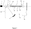
- the figure 1 represents an example of a power fiber optic laser device.
- This device comprises a power laser diode 1 emitting at least one pump wave.
- This power laser diode 1 can be optionally fiberized.
- the optical fiber laser device also comprises an optical resonator 12, also called a cavity, having a totally reflecting end 6 and a partially reflecting end 9.
- completely reflecting end 6 is meant a totally or almost totally reflecting end.
- the ends 6 and 9 may be mirrors or diffraction gratings tuned to the laser emission wavelength.
- the partially reflecting end 9 is capable of transmitting part of the laser beam outside the optical resonator 12 and reflecting another part of the laser beam inside the optical resonator 12.
- the ends 6 and 9 reflect the beam the emission wavelength of the laser.
- the optical resonator 12 comprises a multimode optical fiber 7 amplifying.
- This multimode optical fiber 7 is a double-clad fiber composed of a silica or glass core doped with ions of a rare earth such as ytterbium, neodynium, thulium or erbium.
- the typical diameter of this core is between 20 and 100 microns although larger diameters are possible.
- This core 20 is surrounded by a first sheath 21 called pumping sheath, typically between 100 and 800 microns diameter.
- This second pumping sheath 21 is surrounded by a containment sheath 22 whose index is significantly lower than that of the pumping sheath 21.
- the containment sheath 22 may be composed of a set of capillaries filled with air, a low index polymer or any other non-absorbent material.
- This confinement sheath 22 may be surrounded by a mechanical sheath 13 ensuring the mechanical strength of the fiber.
- the multimode optical fiber 7 may be intrinsically rigid (diameter> 1 mm) or flexible.
- the power laser diode 1 has a wavelength adjusted to correspond to a dopant absorption band of the core 20. It injects a pump wave into the core 20 of the multimode optical fiber 7.
- Optical means 3, 11 allow coupling of the pump wave in the multimode optical fiber 7 which produces a laser beam therein having a fundamental mode and being able to present modes of higher order.
- This pump radiation creates in the heart 20 an excited population and therefore an optical gain.
- the length of the multimode optical fiber 7 is chosen to ensure sufficient absorption of the pump wave and cavity gain for laser emission.
- the multimode optical fiber 7 has an input face 23 and an output face 24 positioned at its ends.
- the pump wave is injected by the input face 23 which is located near the laser diode 1.
- the output face 24 is located near the partially reflecting end 9.
- the optical resonator 12 comprises at least one sub-module 25, 26.
- the optical resonator 12 comprises two sub-optical modules 25, 26, as described in FIG. figure 1 .
- first optical sub-module 25 formed between the totally reflecting end 6 and the input face 23 of the multimode optical fiber 7 and a second optical sub-module 26 formed between the partially reflecting end 9 and the output face 24 multimode optical fiber 7.
- the figure 2 represents the spatial distribution of the eigen modes of an optical fiber.
- the ordinate 42 represents the gain and the abscissa 43 represents the distance from the center of the fiber.
- the shape of the beam is broken down into high order modes 41 and mode 0 (or fundamental mode 40).
- w at 0.650 + 1619 V - 3 / 2 + 2879 V - 6
- the difficulty is therefore to inject on one of the faces 23, 24 of the optical fiber a light intensity distribution exactly equal to that of the fundamental mode.
- each optical sub-module 25, 26 is designed so that its fundamental mode present on the interface, between the optical submodule 25, 26 and the multimode optical fiber 7 , characteristics equal to or almost equal to that of the fundamental mode of the multimode fiber 7.
- the optical sub-modules 25, 26 thus make it possible to re-imitate the fundamental mode coming from one of the input or output faces 23, 24 of the multimode optical fiber 7 on itself, so as to excite only or almost the fundamental mode of the multimode optical fiber.
- the optical sub-module 25, 26 makes it possible to adapt the dimension w of the fundamental mode of the incident laser beam to one of the input or output faces 23, 24 of the multimode optical fiber 7 so as to produce a single-mode laser beam , or almost, at the output of the other input or output face 23, 24 of the multimode optical fiber 7.
- Each optical sub-module 25, 26 is in fact a spatial filtering means capable of allowing the spatial filtering of the energy of the incident laser beam on the input or output face 23, 24 so as to reduce the gain of the light modes. high order below a gain threshold and to bring the fundamental mode gain above said gain threshold.
- the threshold of gain corresponds to the threshold which makes it possible to obtain a laser effect.
- the filtering means which are the optical submodules 25, 26, are arranged facing the input and output faces 23, 24 of the multimode optical fiber 7, respectively.
- optical sub-modules 25, 26 are independent of the multimode optical fiber 7 amplifying. Optical submodules 25, 26 will favor the fundamental mode and therefore impose a single mode emission even if the amplifying medium is capable of supporting several modes.
- Each optical sub-module 25, 26 comprises optical means 2, 8 having a determined position in the optical sub-module 25, 26 so as to make it possible for the optical sub-module to reproduce in amplitude and in phase, after a round-trip of the laser beam in the latter, the fundamental mode of the multimode optical fiber 7 on the input or output face 23, 24 of said multimode optical fiber 7, minimizing the diffraction losses of the fundamental mode.
- the position of the optical means 2, 8 is also determined in the optical submodule 25, 26 so as to enable the optical submodule to filter the other modes, producing additional diffraction losses on said other modes, minimizing the number of modes. laser propagating in the optical resonator.
- the number of modes of the laser beam at the output of the optical resonator 12 is very much lower than the number of intrinsic modes of the multimode optical fiber 7.
- the first sub-optical module 25 comprises optical means 2, 8 consisting of a lens 2a or several lenses and a mirror 6, positioned so that the characteristics of the fundamental mode of this optical sub-module 25 correspond to the fundamental mode of the multimode optical fiber 7 on the input face 23.
- the second optical sub-module 26 also comprises optical means 2, 8 consisting of a lens 8a or several lenses and a partially reflecting mirror 9, positioned so that the characteristics of the fundamental mode of this optical submodule 26 correspond to the fundamental mode of the multimode optical fiber 7 on the exit face 24.
- the optical means 2, 8 of a sub-module 25, 26 may comprise the input or output face 23, 24 of the multimode optical fiber 7.
- the input or output face 23, 24 may itself be filtering or having an optical power participating in the optical sub-module 25, 26.
- the input or output face 23, 24 of the multimode optical fiber 7 is then worked by cleavage, fusion, polishing or other optical fabrication technique and which makes it possible to obtain a non-zero convergence.
- the mode of operation of the power fiber laser device is described in detail below.
- the power laser diode 1 generates a pump wave which is injected into the multimode optical fiber 7 through a lens 11 focusing the pump wave on a dichroic mirror 3.
- the pump wave is then focused on the face input 23 of the multimode optical fiber 7 through the lens 2a optical means 2 of the first sub-module 25.
- the radiation of the power laser diode 1 is absorbed in the core 20 of the multimode optical fiber 7.
- the multimode optical fiber 7 then emits a second radiation at a wavelength ⁇ which is guided along the multimode optical fiber 7 to the output face 24 of the multimode optical fiber 7. This radiation is then collimated by the lens 8a of the optical means 8 of the second sub-module 26, before being incident on the partially reflecting mirror 9 at the wavelength ⁇ .
- Part of the radiation is therefore sent back into the multimode optical fiber 7.
- the radiation is collimated on the dichroic mirror 3, by the lens 2a of the optical means 2, 8 of the first sub-module 25.
- the totally reflecting end 6 consisting of a totally reflecting mirror closes the optical resonator 12 and sends the radiation back to itself to the multimode optical fiber 7.
- This mirror may be flat or have a curvature.
- the principle of filtering the resonant mode in this fiber laser is to match the geometrical characteristics of the two sub-optical modules 25,26.
- the distances, the focal lengths and the radii of curvature of the various optical elements are adjusted so that the Gaussian beam neck that can resonate in the optical sub-modules 25, 26 corresponds exactly to that of the fundamental mode in the amplifying multimode optical fiber. 7.
- the eigenmode of the first optical sub-module 25 is obtained, for example, with the method of the matrices ABCD ("Laser", Siegmann).
- the input face 13 of the fiber 7 being flat, the Gaussian beam necessarily has a neck at this location.
- This method makes it possible to calculate the size of the eigen mode, ie reimagining in phase and amplitude after a round trip in the first optical sub-module 25 which automatically presents a neck at this same place.
- this calculation involves Gaussian beams and is therefore not equivalent to a geometrical optics calculation. There is no imaging here in the geometric sense of the term but propagation of a Gaussian mode, that is to say of a distribution of energy and a phase front.
- the same method can be applied to calculate the mode of the second optical sub-module 26.
- the figure 4 represents the distances between the optical elements of the second optical sub-module 26 to be taken into account for the calculation.
- the distance L1 corresponds to the distance between the output face of the multimode optical fiber 7 and the lens 8a of the optical means 8 of the second sub-module 26.
- the distance L2 corresponds to the distance between the lens 8a of the optical means 8 of the second sub-module 26 and the partially reflecting mirror 9.
- the above method makes it possible to calculate the distances L1 and L2 so that the fundamental mode is of dimension w on the output face 24.
- the figure 5 represents pairs L1-L2 for which the second optical sub-module 26 resonates for the fundamental mode, for different values of dimension w (or diameter of the mode).
- the figure 5 shows that for each value of w comprised here between 15 and 25 microns, there exists a pair L1-L2 for which the second sub-optical module 26 is resonant for this mode.
- This multimode optical fiber 7 has a fundamental mode of about 18 microns, radius to 1 / e 2 .
- the laser device according to the figure 3 provides spatially multimode radiation.
- Mirrors totally 6 and partially reflecting 9 may be curved or planar.
- the totally reflecting mirror 6 has a radius of curvature of between 100 and 200 mm
- the lens 2a of the optical means 2 of the first submodule 25 is aspherical with a focal length of 8 mm
- the lens 8a means Optics 8 of the second sub-module 26 is aspherical with a focal length of 8 mm
- the partially reflecting mirror 9 is plane.
- the partially reflecting mirror 9 is positioned to accurately return the pump beam from the pump casing to itself. Its position is optimized by a geometrical optics calculation so that the output face 24 of the fiber is imaged on it even after reflection on the partially reflecting mirror 9 with a magnification equal to 1 or -1 and an image numerical aperture equal to the object numerical aperture.
- the optical resonator 12 comprises a lens 4 disposed between the dichroic mirror 3 and the totally reflecting end 6.
- the distances between the optical elements are then recalculated to take account of this lens 4.
- the figure 6 represents another example in which the optical resonator 12 comprises only the first optical sub-module 25.
- This first optical sub-module 25 comprises optical means 2 consisting of a lens 2a and a totally reflecting mirror 6.
- the optical resonator 12 is closed at its other end by an optical closure means.
- the closing optical means closing the optical resonator 12 has both convergence and reflection properties for a light wave.
- It may consist of a single optical element having both convergence and reflection properties for a light wave.
- the closing optical means closing the optical resonator 12 may be the output face 24 of the multimode optical fiber.
- the output face 24 of the multimode optical fiber must have an almost perfect flatness as well as an almost perfect perpendicularity with respect to the axis of the latter in order to fulfill the reimaging conditions of the fundamental mode coming from the core of the fiber on it. -even. If the other side of the optical resonator 12 comprises a first optical sub-module 25 adjusted to the proper mode of the fiber, only the fundamental mode can resonate without loss.
- the exit face 24 may have a curvature provided that the distance between this exit face and the entry of the guiding zone in the optical fiber 7 and the curvature of this face is chosen so as to fulfill the reimaging conditions of the mode. fundamental from the heart of the fiber on itself.
- the spatial filtering used in the optical resonator 12 can also use any system making it possible to discriminate radiations of different divergences.
- optical resonator 12 comprises only the second optical sub-module 26.
- This second optical sub-module 26 comprises an optical means 8 consisting of a lens 8a and a partially reflecting mirror 9. closing optical means closing the optical resonator 12 is formed by the input face 23 of the multimode optical fiber 7.
- the totally reflecting end 6 is formed of the input face 23 of the multimode optical fiber 7.
- the optical means 2, 8 of the two sub-cavities 25, 26 each comprise a monomode fiber tip 36 in contact with one of the input and output faces 23, 24 of the multimode optical fiber 7.
- the laser beam is focused on singlemode fiber ends 36 by lenses 2b, 8b.
- the monomode fiber tip 36 has a core diameter close to that of the multimode optical fiber 7.
- the optical resonator 12 advantageously comprises two monomode fiber tips 36.
- a first monomode fiber tip 36 is placed in contact with the input face 23 of the multimode optical fiber 7 and a second monomode fiber tip 36 is placed in contact with the output face 24 of the multimode optical fiber 7.
- These monomode fiber tips 36 can be obtained from a microstructured fiber.
- An integrated structure is obtained in which the mode filtering is performed by associating one or more singlemode fiber ends 36 with a multimode optical amplifying optical fiber 7.
- the characteristics of the multimode optical fiber 7 and the monomode optical fiber 36 constituting the different sections are calculated. so that their fundamental modes coincide and there is resonance between the fundamental mode of the singlemode fiber ends 36 and the fundamental mode of the multimode optical fiber 7.
- the monomode fiber tips 36 are not doped with lasing ions, they are much easier to achieve.
- the one or more monomode fiber tips 36 may be monomode photonic fibers and the multimode amplifying optical fiber 7 may be a doped fiber (photonic or not).
- the monomode fiber endpieces 36 are, for example, soldered to the doped multimode optical amplifying optical fiber 7 or associated with the fiber by fusion, gluing or deposition.
- the monomode fiber tip 36 contains a so-called "double clad" structure comprising on the one hand a single-mode core 20 and, on the other hand, a pump casing 21 of characteristic (diameter and numerical aperture) equivalent to the doped multimode optical fiber 7 used as an amplifier.
- the optical resonator 12 is closed by the totally reflecting end 6 which may be a spherical mirror whose radius of curvature and position are calculated to ensure that the fundamental mode coming from the monomode fiber endpiece 36 in contact with the first end 23 is imaged without change in size or numerical aperture on the face of this first end 23 after reflection on the spherical mirror 6.
- the filtering of spatial modes can be ensured by any element whose transmission or reflection strongly depends on the impact on this element and in particular a massive Bragg mirror.
- the filtering can also be obtained by special treatment of the mirror (s) of the optical resonator 12.
- the optical resonator 12 may comprise an optical trigger 10 disposed near the fully reflecting end 6. It allows the optical resonator 12 to generate giant light pulses from a pump source emitting continuous radiation.
- the trigger 10 is, preferably, arranged between the totally reflecting end 6 and the dichroic mirror 3.
- the trigger 10 makes it possible to generate nanosecond pulses.
- the remainder of the optical resonator 12 must not couple a part of the energy of the fundamental mode to the other modes.
- the multimode optical fiber 7 is mechanically stiffened by a stabilizing means stabilizing the radius of curvature of the optical fiber multimode 7 to reduce the coupling of the fundamental mode with the higher order modes.
- the means of stabilization of the multimode optical fiber 7 comprises a mechanical sheath 13 (rod-type rigid type) of large diameter surrounding said multimode optical fiber 7 so as to stiffen the multimode optical fiber 7.
- a mechanical sheath 13 (rod-type rigid type) of large diameter surrounding said multimode optical fiber 7 so as to stiffen the multimode optical fiber 7.
- the figure 9 represents a cross section of a multimode optical fiber 7 comprising a core 20 surrounded by a pump sheath 21, itself surrounded by a confinement sheath 22 which is surrounded by a mechanical sheath 13 which may be made of glass.
- the stabilization means of the multimode optical fiber 7 comprises a cylindrical support 14 dug a groove 16 at its periphery 17.
- the groove 16 is hollowed around the cylindrical support 14 helically.
- the multimode optical fiber 7 is inserted into this groove 16 so as to block it by voltage or pressure.
- the cylindrical support 14 comprises two input and output media 29 through which the multimode optical fiber 7 enters and leaves the cylindrical support 14.
- the lenses 2a, 8a of the optical means 2, 8 of the optical sub-modules 25, 26 can be disposed in front of these two input media 28 and output 29 and in front of the input face 23 and the output face 24 of the multimode optical fiber 7.
- These two input media 28 and output 29 comprise a groove identical to that of the cylindrical support 14 for inserting the multimode optical fiber 7 therein.
- the multimode optical fiber 7 is preferentially flexible.
- the means for stabilizing the multimode optical fiber 7 comprises a linear support 15 cut by a groove in which the multimode optical fiber 7 is inserted along a longitudinal axis 19.
- a second piece 33 covers the multimode optical fiber 7 so as to block it by pressure.
- the grooves are machined in a rigid material and, if possible, a good heat conductor so as to minimize the thermal effects on the multimode optical fiber 7. It is important that the whole of the multimode optical fiber 7 is in contact with the rigid support 14, 15.
- the groove 16 has dimensions adapted to the insertion of the multimode optical fiber 7.
- the multimode optical fiber 7 is semi-rigid or flexible and its radius of curvature can go to infinity.
- the micro or macro curvatures of the fiber introduce couplings between the polarization states. It is therefore very difficult to maintain a stable polarization state with a flexible fiber, especially if it is multimode.
- the stabilization means according to the invention makes it possible to maintain a stable polarization state for the fiber.
- an acousto-optic or electro-optical trigger element it is possible to introduce into the optical resonator 12, an acousto-optic or electro-optical trigger element, to allow to have a gain or a loss varying according to the state of polarization. It is possible to obtain polarized radiation even if the multimode amplifier medium is not polarization-preserving. It also makes it possible to obtain polarized continuous or pulsed radiation.
- the invention also relates to a power fiber optic laser system comprising a power fiber optic laser device, as previously described, and a double-clad amplifying multimode optical fiber.
- the light signal transmitted by the partially reflecting end 9 of the optical resonator 12 is coupled to one of the faces of the amplifying multimode optical fiber so as to adapt the dimension of the fundamental mode of the transmitted laser beam with the dimension of the face of the multimode optical fiber amplifier.
- a maximum of the stimulated radiation excited by the pump wave is coupled to the fundamental mode.
- the 1 / e2 diameter is substantially smaller than the doped core diameter (36 microns in a 50 micron fiber in the case presented).
- the index jump fiber whose core is totally doped is not the fiber best adapted to the coupling of the pump energy in the fundamental mode. It is therefore possible, in a particular embodiment, to optimize the laser device by using an optical fiber whose guiding core has doping which is not uniform transversely. This has the double advantage of favoring the fundamental pump-mode coupling and thus the laser efficiency and of facilitating the mode filtering previously described.
- This type of coupling is also possible with an optical fiber having a variable index in all or part of the guiding core.
- the power fiber optic laser device provides a stable monomode radiation with excellent fundamental mode efficiency from a multimode fiber of arbitrarily large diameter, without risk to the longevity of the fiber.
Description
L'invention concerne un dispositif laser à fibre optique de puissance permettant d'obtenir un rayonnement spatialement monomode à partir d'une fibre optique multimode.The invention relates to a power optical fiber laser device for obtaining spatially monomode radiation from a multimode optical fiber.
On entend par rayonnement monomode, un rayonnement dont la divergence est proche du minimum imposé par la diffraction du profil en intensité dudit rayonnement.Monomode radiation is a radiation whose divergence is close to the minimum imposed by the diffraction of the intensity profile of said radiation.
Les lasers à solide sont composés d'au moins un milieu amplificateur et d'un résonateur optique formé par un ensemble de miroirs. Les propriétés spatiales du faisceau de sortie sont données par les caractéristiques de ce résonateur.Solid state lasers are composed of at least one amplifying medium and an optical resonator formed by a set of mirrors. The spatial properties of the output beam are given by the characteristics of this resonator.
On peut en particulier montrer que si le résonateur est dit stable, la forme du faisceau peut se décomposer sur une base de fonctions de Hermite Gauss. Ces fonctions sont appelées les modes de la cavité.In particular, it can be shown that if the resonator is said to be stable, the shape of the beam can decompose on a basis of Hermite Gauss functions. These functions are called the modes of the cavity.
Parmi ces modes, le mode fondamental a une forme gaussienne et possède la plus petite divergence. Il est souvent privilégié par l'utilisateur puisqu'il permet la focalisation la plus petite. Néanmoins, la zone excitée dans le milieu amplificateur possède une dimension propre qui ne dépend que de la façon dont l'énergie a été répartie dans le milieu et aucunement du résonateur.Among these modes, the fundamental mode has a Gaussian form and has the smallest divergence. It is often favored by the user since it allows the smallest focus. Nevertheless, the zone excited in the amplifying medium has a proper dimension which depends only on the way in which the energy has been distributed in the medium and not on the resonator.
Lorsque cette zone excitée est plus large que le diamètre du mode fondamental à cet endroit de la cavité, une partie de l'énergie est couplée sur des modes d'ordre supérieur et le faisceau produit devient multimode. Les modes d'ordre élevé présentent une divergence plus grande et se focalisent donc sur une zone de plus grand diamètre. On peut aussi expliquer ce phénomène en considérant que tout mode voit un certain gain dans le milieu amplificateur et subit des pertes par propagation.When this excited zone is wider than the fundamental mode diameter at this point in the cavity, a portion of the energy is coupled to higher order modes and the produced beam becomes multimode. Higher order modes have greater divergence and thus focus on a larger diameter area. This phenomenon can also be explained by considering that any mode sees a certain gain in the amplifying medium and suffers losses by propagation.
Seuls les modes dont le gain dépasse les pertes peuvent produire un effet laser. Le gain d'un mode dépend du recouvrement de ce mode et de la zone excitée dans le milieu amplificateur.Only modes whose gain exceeds losses can produce a laser effect. The gain of a mode depends on the recovery of this mode and the zone excited in the amplifying medium.
Au total, afin de rendre le laser spatialement monomode, il convient de concevoir le résonateur de façon à ce que les dimensions du mode fondamental et de la zone excitée coïncident le mieux possible.In total, in order to make the laser spatially monomode, it is necessary to design the resonator so that the dimensions of the fundamental mode and the excited area coincide as well as possible.
Si ceci n'est pas possible, par exemple pour des questions de longueur du résonateur, on peut forcer le fonctionnement monomode du résonateur en introduisant une ouverture dont le diamètre est calculé afin de correspondre exactement à celui du mode fondamental à l'endroit de l'ouverture. Les pertes subies par les modes d'ordre élevé lors du passage dans le trou sont suffisamment importantes pour amener ces derniers en dessous du seuil de l'effet laser et ne permettre un effet laser que pour le mode fondamental.If this is not possible, for example for resonator length issues, the monomode operation of the resonator can be introducing an opening whose diameter is calculated to exactly match that of the fundamental mode at the location of the opening. The losses suffered by the higher order modes during the passage in the hole are large enough to bring them below the threshold of the laser effect and allow a laser effect only for the fundamental mode.
Les lasers à fibre se distinguent des lasers à solide classiques par le fait que le milieu amplificateur possède une structure guidante qui impose certaines caractéristiques spatiales au faisceau le traversant.Fiber lasers are distinguished from conventional solid state lasers in that the amplifying medium has a guiding structure which imposes certain spatial characteristics on the beam passing through it.
Ainsi certaines fibres ne permettent le guidage que de faisceaux monomodes alors que d'autres supportent plusieurs modes. Lorsqu'une telle fibre est incluse dans un résonateur optique on obtient un laser à fibre dont les caractéristiques spatiales sont généralement imposées par la fibre. En particulier si la fibre est monomode, le laser ne peut être que monomode.Thus some fibers allow the guidance of single-mode beams while others support several modes. When such a fiber is included in an optical resonator, a fiber laser is obtained whose spatial characteristics are generally imposed by the fiber. In particular, if the fiber is monomode, the laser can only be monomode.
Ce cas particulier est très favorable mais ne peut pas toujours être mis en oeuvre. En particulier, le nombre de modes supportés par la fibre est fonction du diamètre du coeur de la fibre et de la différence d'indice entre le coeur et la gaine.This particular case is very favorable but can not always be implemented. In particular, the number of modes supported by the fiber is a function of the diameter of the core of the fiber and the index difference between the core and the sheath.
Afin de garder une propagation purement monomode lorsque le diamètre du coeur augmente, il faut diminuer le saut d'indice entre le coeur et la gaine. La technologie de fabrication des fibres ne permet pas d'obtenir actuellement des fibres monomodes dont le coeur présente un diamètre supérieur à environ 20 microns. Etant donné le seuil de dommage de la silice ou du verre qui compose le coeur de ces fibres, il n'est donc pas possible de dépasser certaines limites en puissance moyenne dans le cas des lasers continus ou puissance de crête pour les lasers pulsés.In order to keep a purely monomode propagation when the diameter of the core increases, it is necessary to reduce the index jump between the core and the sheath. The fiber manufacturing technology does not currently make it possible to obtain monomode fibers whose core has a diameter greater than about 20 microns. Given the damage threshold of the silica or glass that makes up the core of these fibers, it is therefore not possible to exceed certain limits in average power in the case of continuous lasers or peak power for pulsed lasers.
Afin d'augmenter la puissance accessible il faut accepter de perdre en qualité spatiale et utiliser des fibres multimodes. Une solution a été trouvée à travers l'utilisation de fibres dites photoniques ou à couches photoniques ou MPF (« Multiclad Photonic Fiber ») pour lesquelles on peut moduler l'indice effectif en introduisant des capillaires remplis d'air dans la gaine.In order to increase the accessible power it is necessary to accept to lose in spatial quality and to use multimode fibers. A solution has been found through the use of so-called photonic or photonic layer or MPF fibers ("Multiclad Photonic Fiber") for which the effective index can be modulated by introducing capillaries filled with air into the sheath.
De telles fibres sont décrites dans l'article de
Néanmoins la fabrication de ces fibres est compliquée et repose sur une parfaite maîtrise et uniformité de l'indice du coeur. Ceci n'est pas compatible avec de forts dopages et il faut de nouveau accepter un compromis entre diamètre de coeur et uniformité de dopage.Nevertheless the manufacture of these fibers is complicated and relies on a perfect control and uniformity of the index of the heart. This is not compatible with high doping and we must again accept a compromise between core diameter and uniformity of doping.
En particulier, le coeur même de la fibre peut être micro structuré afin de garantir un indice moyen parfaitement contrôlé. Pour cela, on introduit dans le coeur des zones non dopées en verre ou en air. La surface relative de ces zones donne un contrôle quasi parfait de l'indice mais impose des dopages localement très importants pour assurer une absorption du coeur à la longueur d'onde utilisée suffisante pour exciter le milieu amplificateur.In particular, the core of the fiber can be micro structured to ensure a perfectly controlled average index. For this purpose, undoped areas of glass or air are introduced into the core. The relative surface area of these zones gives almost perfect control of the index but imposes doping locally very important to ensure absorption of the core at the wavelength used sufficient to excite the amplifying medium.
Ces surconcentrations donnent lieu, au cours du temps, à des effets secondaires indésirables.These overconcentrations give rise over time to undesirable side effects.
Dans le document
Cette technique a été utilisée dans un amplificateur en injectant une source extérieure sur la face d'entrée de la fibre multimode. Cette méthode d'injection sélective nécessite un signal externe dont le faisceau est parfaitement gaussien et ne s'applique donc pas à un oscillateur.This technique was used in an amplifier by injecting an external source onto the input face of the multimode fiber. This selective injection method requires an external signal whose beam is perfectly Gaussian and therefore does not apply to an oscillator.
Il est aussi connu que toute courbure ou variation de position de la fibre à tendance à coupler une partie du rayonnement de ce mode vers des modes d'ordre élevé, rendant ainsi le rayonnement multimode en sortie de la fibre mais peut aussi coupler tout ou partie du rayonnement multimode vers la gaine, introduisant ainsi des pertes sur ces modes d'ordre supérieur.It is also known that any curvature or variation of position of the fiber tends to couple a portion of the radiation of this mode to high order modes, thus making the multimode radiation output of the fiber but can also couple all or part multimode radiation to the sheath, thus introducing losses on these higher order modes.
Dans le document
Néanmoins cette méthode entraîne inéluctablement des pertes sur le mode fondamental et elle est difficile à mettre en oeuvre sur des fibres courtes puisqu'elle nécessite un enroulement sur plusieurs tours de diamètre compris entre 5 et 15 cm ce qui correspond à des longueurs de fibre supérieures à 1 m.However, this method inevitably leads to losses in the fundamental mode and is difficult to implement on short fibers since it requires a winding on several turns of diameter between 5 and 15 cm which corresponds to fiber lengths greater than 1 m.
Par ailleurs, la présence de plusieurs modes dans le rayonnement issu de la fibre rend difficile voire impossible l'obtention d'un rayonnement polarisé.Moreover, the presence of several modes in the radiation from the fiber makes it difficult or impossible to obtain polarized radiation.
Il n'existe pour l'instant pas de solution convenable pour les lasers à fibre permettant d'obtenir un mode unique de grande dimension transverse, sans risque pour la longévité de la fibre. Dans les documents
A cet effet, l'invention concerne, un dispositif laser à fibre optique de puissance selon la revendication 1. Selon l'invention, le sous module optique 25, 26 est un moyen de filtrage spatial comprenant des moyens optiques 2, 8 ayant une position déterminée dans le sous module optique 25, 26 de façon à rendre apte le sous module optique à reproduire en amplitude et en phase, après un aller retour du faisceau laser dans ce dernier, le mode fondamental de la fibre optique multimode 7 sur la face d'entrée ou de sortie 23, 24 de ladite fibre optique multimode 7, minimisant les pertes du mode fondamental, et de façon à rendre apte le sous module optique à filtrer les autres modes, produisant dans le résonateur optique des pertes supplémentaires sur lesdits autres modes, minimisant le nombre de modes laser se propageant dans le résonateur optique.For this purpose, the invention relates to a power optical fiber laser device according to
Dans différents modes de réalisation possibles, la présente invention concerne également les caractéristiques qui ressortiront au cours de la description qui va suivre et qui devront être considérées isolément ou selon toutes leurs combinaisons techniquement possibles :
- le résonateur optique comprend deux sous modules, disposés chacun à l'une des extrémités de la fibre optique multimode,
- le résonateur optique comprend un seul sous module optique, disposé à l'une des extrémités de la fibre optique multimode, le résonateur optique étant fermé à son autre extrémité par un moyen optique de fermeture,
- le moyen optique de fermeture fermant le résonateur optique consiste en l'une des faces d'entrée ou de sortie de la fibre optique multimode, ladite face d'entrée ou de sortie étant plane et perpendiculaire à l'axe optique de la fibre optique,
- le moyen optique de fermeture fermant le résonateur optique est constitué d'un unique élément optique présentant à la fois des propriétés de convergence et de réflexion pour une onde lumineuse,
- les moyens optiques d'un sous module optique comprennent une ou plusieurs lentilles associées à l'une des extrémités réfléchissantes,
- les moyens optiques d'un sous module optique comprennent la face d'entrée ou de sortie de la fibre optique multimode, ladite face d'entrée ou de sortie ayant une convergence propre participant à la fonction de filtrage,
- les moyens optiques d'un sous module optique comprennent un embout de fibre monomode en contact avec l'une des faces d'entrée et de sortie de la fibre optique multimode, le faisceau laser étant focalisé sur ledit embout de fibre monomode par une lentille,
- le coeur de la fibre optique multimode présente un profil radial de dopage non-uniforme de manière à favoriser le gain du mode fondamental,
- la fibre optique multimode dispose de moyen de filtrages propres lui permettant d'être faiblement multimode,
- la fibre optique multimode est mécaniquement rigidifiée par un moyen de stabilisation,
- le moyen de stabilisation de la fibre optique multimode consiste en une gaine mécanique de gros diamètre entourant ladite fibre optique multimode,
- le moyen de stabilisation de la fibre optique multimode consiste en un support cylindrique creusé d'un sillon sur sa périphérie de façon hélicoïdale, ladite fibre optique multimode étant insérée dans ledit sillon de façon à être bloquée par tension,
- le moyen de stabilisation de la fibre optique multimode consiste en un support linéaire creusé d'un sillon dans lequel la fibre optique multimode est insérée suivant un axe longitudinal, ladite fibre optique multimode étant recouverte d'une deuxième pièce de façon à la bloquer par pression,
- le résonateur optique comprend un déclencheur optique disposé à proximité d'une des extrémités réfléchissantes permettant au résonateur optique de générer des impulsions lasers,
- le dispositif laser à fibre optique de puissance comprend un ou plusieurs moyens optiques polarisants.
- the optical resonator comprises two sub-modules, each disposed at one end of the multimode optical fiber,
- the optical resonator comprises a single optical sub-module disposed at one end of the multimode optical fiber, the optical resonator being closed at its other end by an optical closure means,
- the optical closure means closing the optical resonator consists of one of the input or output faces of the multimode optical fiber, said input or output face being flat and perpendicular to the optical axis of the optical fiber,
- the optical closing means closing the optical resonator consists of a single optical element having both convergence and reflection properties for a light wave,
- the optical means of an optical sub-module comprise one or more lenses associated with one of the reflective ends,
- the optical means of an optical sub-module comprise the input or output face of the multimode optical fiber, said input or output face having a specific convergence participating in the filter function,
- the optical means of an optical submodule comprise a single-mode fiber endpiece in contact with one of the input and output faces of the multimode optical fiber, the laser beam being focused on said single-mode fiber endpiece by a lens,
- the core of the multimode optical fiber has a non-uniform doping radial profile so as to favor the gain of the fundamental mode,
- the multimode optical fiber has clean filtering means allowing it to be weakly multimode,
- the multimode optical fiber is mechanically stiffened by a stabilizing means,
- the means for stabilizing the multimode optical fiber consists of a large-diameter mechanical sheath surrounding said multimode optical fiber,
- the means for stabilizing the multimode optical fiber consists of a cylindrical support hollowed out of a groove on its periphery in a helical manner, said multimode optical fiber being inserted into said groove so as to be clamped by tension,
- the means for stabilizing the multimode optical fiber consists of a linear support formed by a groove in which the multimode optical fiber is inserted along a longitudinal axis, said multimode optical fiber being covered with a second part so as to block it by pressure ,
- the optical resonator comprises an optical trigger arranged near one of the reflective ends allowing the optical resonator to generate laser pulses,
- the optical fiber laser device comprises one or more polarizing optical means.
L'invention concerne également un système laser à fibre optique de puissance comprenant un dispositif laser à fibre optique de puissance décrit précédemment.The invention also relates to a power fiber optic laser system comprising a power fiber laser device described above.
Selon l'invention, le système laser à fibre optique de puissance comprend une fibre optique multimode amplificatrice double gaine, le signal lumineux transmis par l'extrémité partiellement réfléchissante du résonateur optique étant couplé à l'une des faces de la fibre optique multimode amplificatrice de façon à n'exciter uniquement ou quasiment que le mode fondamental de la fibre optique multimode amplificatrice double gaine.According to the invention, the power optical fiber laser system comprises a double-sheath amplifying multimode optical fiber, the light signal transmitted by the partially reflecting end of the optical resonator being coupled to one of the faces of the multimode optical fiber. amplifier so as to excite only or almost the fundamental mode of the multimode optical fiber amplifying double sheath.
L'invention sera décrite plus en détail en référence aux dessins annexés dans lesquels :
- la
figure 1 représente un dispositif laser à fibre optique de puissance - la
figure 2 représente la répartition spatiale des modes propres d'une fibre optique ; - la
figure 3 représente un dispositif laser à fibre optique de puissance comprenant deux sous modules optiques comportant chacun une lentille et un miroir totalement ou partiellement réfléchissant; - la
figure 4 représente les distances approximatives entre les éléments optiques afin de remplir les conditions de filtrage ; - la
figure 5 représente des couples L1-L2 pour lesquels le deuxième sousmodule 26 résonne pour le mode fondamental, pour différentes valeurs de dimension w ; - la
figure 6 représente un dispositif laser à fibre optique de puissance; - la
figure 7 représente un dispositif laser à fibre optique de puissance comprenant deux embouts de fibre monomode selon un autre mode de réalisation de l'invention ; - la
figure 8 représente un dispositif laser à fibre optique de puissance comprenant un déclencheur; - la
figure 9 représente une coupe transversale d'une fibre optique multimode entourée d'une gaine mécanique ; - la
figure 10 représente un moyen de stabilisation de la fibre optique multimode en forme de cylindre ; - la
figure 11 représente un support linéaire permettant de stabiliser la fibre optique multimode.
- the
figure 1 represents a laser device with optical fiber power - the
figure 2 represents the spatial distribution of the eigen modes of an optical fiber; - the
figure 3 represents a power optical fiber laser device comprising two sub-optical modules each comprising a lens and a totally or partially reflecting mirror; - the
figure 4 represents the approximate distances between the optical elements in order to fulfill the filtering conditions; - the
figure 5 represents pairs L1-L2 for which the second sub-module 26 resonates for the fundamental mode, for different values of dimension w; - the
figure 6 represents a power fiber optic laser device; - the
figure 7 represents a power optical fiber laser device comprising two monomode fiber tips according to another embodiment of the invention; - the
figure 8 represents a power optical fiber laser device comprising a trigger; - the
figure 9 represents a cross section of a multimode optical fiber surrounded by a mechanical sheath; - the
figure 10 represents a means of stabilizing the multimode optical fiber in the form of a cylinder; - the
figure 11 represents a linear support for stabilizing the multimode optical fiber.
La
Ce dispositif comprend une diode laser de puissance 1 émettant au moins une onde de pompe. Cette diode laser de puissance 1 peut être éventuellement fibrée.This device comprises a
Le dispositif laser à fibre optique de puissance comprend également un résonateur optique 12, appelé également cavité, comportant une extrémité totalement réfléchissante 6 et une extrémité partiellement réfléchissante 9.The optical fiber laser device also comprises an
On entend par extrémité totalement réfléchissante 6, une extrémité totalement ou presque totalement réfléchissante.By completely reflecting
Les extrémités 6 et 9 peuvent être des miroirs ou des réseaux de diffractions accordés sur la longueur d'onde d'émission laser. L'extrémité partiellement réfléchissante 9 est capable de transmettre une partie du faisceau laser à l'extérieur du résonateur optique 12 et de réfléchir une autre partie du faisceau laser à l'intérieur du résonateur optique 12. Les extrémités 6 et 9 réfléchissent le faisceau à la longueur d'onde d'émission du laser.The ends 6 and 9 may be mirrors or diffraction gratings tuned to the laser emission wavelength. The partially reflecting
Le résonateur optique 12 comprend une fibre optique multimode 7 amplificatrice. Cette fibre optique multimode 7 est une fibre double gaine composé d'un coeur 20 en silice ou en verre dopé par des ions d'une terre rare comme l'ytterbium, le neodynium, le thulium ou l'erbium.The
Le diamètre typique de ce coeur 20 est compris entre 20 et 100 microns bien que des diamètres supérieurs soient possibles.The typical diameter of this core is between 20 and 100 microns although larger diameters are possible.
Ce coeur 20 est entouré d'une première gaine 21 dite gaine de pompage, de diamètre compris typiquement entre 100 et 800 microns.This
Cette seconde gaine de pompage 21 est entourée d'une gaine de confinement 22 dont l'indice est nettement inférieur à celui de la gaine de pompage 21. La gaine de confinement 22 peut être composée par un ensemble de capillaires remplis d'air, un polymère de bas indice ou tout autre matériau non absorbant.This
Cette gaine de confinement 22 peut être entourée d'une gaine mécanique 13 assurant la tenue mécanique de la fibre. La fibre optique multimode 7 peut être intrinsèquement rigide (diamètre > 1 mm) ou souple.This
La diode laser de puissance 1 présente une longueur d'onde ajustée pour correspondre à une bande d'absorption des dopants du coeur 20. Elle injecte une onde de pompe dans le coeur 20 de la fibre optique multimode 7.The
Des moyens optiques 3, 11 permettent le couplage de l'onde de pompe dans la fibre optique multimode 7 qui produit dans celle-ci un faisceau laser présentant un mode fondamental et pouvant présenter des modes d'ordre supérieur.Optical means 3, 11 allow coupling of the pump wave in the multimode
Ce rayonnement de pompe crée dans le coeur 20 une population excitée et donc un gain optique.This pump radiation creates in the
La longueur de la fibre optique multimode 7 est choisie pour assurer une absorption suffisante de l'onde de pompe et un gain de cavité permettant l'émission laser.The length of the multimode
La fibre optique multimode 7 présente une face d'entrée 23 et une face de sortie 24 positionnées à ses extrémités. L'onde de pompe est injectée par la face d'entrée 23 qui se situe à proximité de la diode laser 1. La face de sortie 24 se situe à proximité de l'extrémité partiellement réfléchissante 9.The multimode
Le résonateur optique 12 comprend au moins un sous module 25, 26.The
Dans un mode de réalisation de l'invention, le résonateur optique 12 comprend deux sous modules optiques 25, 26, comme décrit sur la
Il comprend un premier sous module optique 25 formé entre l'extrémité totalement réfléchissante 6 et la face d'entrée 23 de la fibre optique multimode 7 et un deuxième sous module optique 26 formé entre l'extrémité partiellement réfléchissante 9 et la face de sortie 24 de la fibre optique multimode 7.It comprises a first optical sub-module 25 formed between the totally reflecting
Une fibre à saut d'indice peut être caractérisée par un paramètre appelé fréquence réduite V donné par : ![]()
- a : rayon du coeur de la fibre
- λ: longueur d'onde laser
- NA: ouverture numérique du coeur de la fibre
- η1: indice du coeur de la fibre
- n2: indice de la gaine de pompe
- a: radius of the heart of the fiber
- λ: laser wavelength
- NA: numerical aperture of the fiber core
- η 1 : index of the core of the fiber
- n 2 : index of the pump sheath
Le nombre de mode supporté par une fibre multimode est donné par: ![]()
![]()
Ceci revient à écrire : ![]()
![]()
Le nombre de modes susceptibles de se propager dans une fibre croit très rapidement avec le diamètre de coeur de celle-ci. Bien que nombreux, comme le montre la
La
La forme du faisceau se décompose en modes d'ordre élevé 41 et en mode d'ordre 0 (ou mode fondamental 40).The shape of the beam is broken down into
Le mode d'ordre 0, représenté sur la figure par la courbe 40, présente une forme gaussienne et son intensité décroît radialement suivant la loi suivante : ![]()
![]()
La dimension w du mode d'ordre 0, appelé mode fondamental, dans la fibre est donnée approximativement par la formule : ![]()
![]()
Il est possible, d'après ces expressions, de forcer la fibre optique à guider le mode fondamental. Si l'intensité lumineuse incidente à l'entrée de l'une des faces 23, 24 de la fibre optique correspond à un mode propre de propagation dans cette fibre, l'énergie reste confinée dans ce mode et ne peut exciter de mode d'ordre supérieur.It is possible, according to these expressions, to force the optical fiber to guide the fundamental mode. If the light intensity incident at the entrance of one of the
On retrouve donc en sortie de la fibre optique un profil d'intensité lumineux exactement égal à celui du mode injecté.There is therefore at the output of the optical fiber a luminous intensity profile exactly equal to that of the injected mode.
La difficulté est donc d'injecter sur l'une des faces 23, 24 de la fibre optique une répartition d'intensité lumineuse exactement égale à celle du mode fondamental.The difficulty is therefore to inject on one of the
Seules certaines répartitions en amplitude et phase d'une onde peuvent se propager à travers un sous module optique 25, 26 sans déformation, à condition que les caractéristiques optique et géométrique du sous module optique 25, 26 soient compatibles avec une propagation stable au sens de l'optique gaussienne. On peut ainsi trouver des répartitions très particulières qui se reproduisent avec un minimum de pertes, voire sans perte par diffraction, après un aller-retour dans ledit sous module optique 25, 26. Ces répartitions peuvent être considérés comme des modes propres de propagation du sous module optique 25, 26, le mode fondamental ayant une répartition gaussienne d'intensité. Lorsqu'une répartition lumineuse (en amplitude et phase) correspondant à un mode propre du sous module optique 25, 26 est placée sur la face d'entrée du sous module optique 25, 26, cette répartition se retrouve sans changement ni perte après avoir effectué un aller retour dans le sous module optique 25, 26.Only certain amplitude and phase distributions of a wave can propagate through an
Inversement, une onde dont les caractéristiques ne correspondent pas au mode fondamental du sous module optique 25, 26 va d'une part subir des pertes par diffraction dans le sous module optique 25, 26 et d'autre part voir sa répartition d'amplitude et de phase totalement transformée par le passage à travers le sous module optique 25, 26.Conversely, a wave whose characteristics do not correspond to the fundamental mode of the optical sub-module 25, 26 will on the one hand suffer losses by diffraction in the optical sub-module 25, 26 and on the other hand see its amplitude distribution and phase completely transformed by the passage through the optical sub-module 25, 26.
Pour résoudre le problème de filtrage des modes dans une fibre multimode, chaque sous module optique 25, 26 est conçu de façon à ce que son mode fondamental présente sur l'interface, entre le sous module optique 25, 26 et la fibre optique multimode 7, des caractéristiques égales ou quasiment égales à celle du mode fondamental de la fibre multimode 7. Les sous modules optiques 25, 26 permettent ainsi de réimager le mode fondamental issu de l'une des faces d'entrée ou de sortie 23, 24 de la fibre optique multimode 7 sur lui-même, de façon à exciter uniquement ou quasiment que le mode fondamental de la fibre optique multimode. L'imagerie s'entend ici au sens des faisceaux gaussiens et non pas des rayons lumineux, c'est à dire qu'un faisceau ré-imagé sur lui même présente après un aller retour dans un système optique une répartition d'amplitude et de phase identique à celle de l'onde incidente.To solve the mode filtering problem in a multimode fiber, each optical sub-module 25, 26 is designed so that its fundamental mode present on the interface, between the
Le sous module optique 25, 26 permet d'adapter la dimension w du mode fondamental du faisceau laser incident sur l'une des faces d'entrée ou de sortie 23, 24 de la fibre optique multimode 7 de façon à produire un faisceau laser monomode, ou quasiment, en sortie de l'autre face d'entrée ou de sortie 23, 24 de la fibre optique multimode 7.The optical sub-module 25, 26 makes it possible to adapt the dimension w of the fundamental mode of the incident laser beam to one of the input or output faces 23, 24 of the multimode
Chaque sous module optique 25, 26 est en fait un moyen de filtrage spatial apte à permettre le filtrage spatial de l'énergie du faisceau laser incident sur la face d'entrée ou de sortie 23, 24 de façon à réduire le gain des modes d'ordre élevé en dessous d'un seuil de gain et à amener le gain du mode fondamental au dessus dudit seuil de gain.Each optical sub-module 25, 26 is in fact a spatial filtering means capable of allowing the spatial filtering of the energy of the incident laser beam on the input or
Le seuil de gain correspond au seuil qui permet d'obtenir un effet laser.The threshold of gain corresponds to the threshold which makes it possible to obtain a laser effect.
Les moyens de filtrage que sont les sous modules optiques 25, 26 sont disposés face aux faces d'entrée et de sortie 23, 24 de la fibre optique multimode 7, respectivement.The filtering means, which are the
Les sous modules optiques 25, 26 sont indépendants de la fibre optique multimode 7 amplificatrice. Les sous modules optiques 25, 26 vont privilégier le mode fondamental et par conséquent imposer une émission monomode même si le milieu amplificateur est susceptible de supporter plusieurs modes.The
Chaque sous module optique 25, 26 comprend des moyens optiques 2, 8 ayant une position déterminée dans le sous module optique 25, 26 de façon à rendre apte le sous module optique à reproduire en amplitude et en phase, après un aller retour du faisceau laser dans ce dernier, le mode fondamental de la fibre optique multimode 7 sur la face d'entrée ou de sortie 23, 24 de ladite fibre optique multimode 7, minimisant les pertes par diffraction du mode fondamental.Each optical sub-module 25, 26 comprises
La position des moyens optiques 2, 8 est également déterminée dans le sous module optique 25, 26 de façon à rendre apte le sous module optique à filtrer les autres modes, produisant des pertes par diffraction supplémentaires sur lesdits autres modes, minimisant le nombre de modes laser se propageant dans le résonateur optique.The position of the
On recherche préférentiellement à reproduire le mode fondamental de la fibre optique multimode 7 et à minimiser les pertes par diffraction de ce mode.It is preferentially sought to reproduce the fundamental mode of the multimode
Même si les sous modules 25, 26 ne filtre pas la totalité des modes non fondamentaux, le nombre de modes du faisceau laser en sortie du résonateur optique 12 est très nettement inférieur au nombre de modes intrinsèques de la fibre optique multimode 7.Even if the sub-modules 25, 26 do not filter all the non-fundamental modes, the number of modes of the laser beam at the output of the
Dans le mode de réalisation, représenté sur la
La deuxième sous module optique 26 comprend également des moyens optiques 2, 8 consistant en une lentille 8a ou plusieurs lentilles et un miroir partiellement réfléchissant 9, positionnés de façon à ce que les caractéristiques du mode fondamental de ce sous module optique 26 correspondent au mode fondamental de la fibre optique multimode 7 sur la face de sortie 24.The second optical sub-module 26 also comprises
Les moyens optiques 2, 8 d'un sous module 25, 26 peuvent comprendre la face d'entrée ou de sortie 23, 24 de la fibre optique multimode 7. La face d'entrée ou de sortie 23, 24 peut être elle-même filtrante ou avoir une puissance optique participant au sous module optique 25, 26.The optical means 2, 8 of a sub-module 25, 26 may comprise the input or
La face d'entrée ou de sortie 23, 24 de la fibre optique multimode 7 est alors travaillée par clivage, fusion, polissage ou autre technique de réalisation optique et qui permet d'obtenir une convergence non nulle.The input or
Le mode de fonctionnement du dispositif laser à fibre optique de puissance est décrit en détail ci-dessous.The mode of operation of the power fiber laser device is described in detail below.
La diode laser de puissance 1 génère une onde de pompe qui est injectée dans la fibre optique multimode 7 au travers d'une lentille 11 focalisant l'onde de pompe sur un miroir dichroïque 3. L'onde de pompe est ensuite focalisée sur la face d'entrée 23 de la fibre optique multimode 7 par la lentille 2a des moyens optiques 2 du premier sous module 25. Le rayonnement de la diode laser de puissance 1 est absorbé dans le coeur 20 de la fibre optique multimode 7.The
La fibre optique multimode 7 émet alors un second rayonnement à une longueur d'onde λ qui est guidé tout au long de la fibre optique multimode 7 jusqu'à la face de sortie 24 de la fibre optique multimode 7. Ce rayonnement est ensuite collimaté par la lentille 8a des moyens optiques 8 du deuxième sous module 26, avant d'être incident sur le miroir partiellement réfléchissant 9 à la longueur d'onde λ.The multimode
Une partie du rayonnement est donc renvoyée dans la fibre optique multimode 7. En sortie de la face d'entrée 23 de la fibre optique multimode 7, le rayonnement est collimaté sur le miroir dichroïque 3, par la lentille 2a des moyens optiques 2, 8 du premier sous module 25.Part of the radiation is therefore sent back into the multimode
L'extrémité totalement réfléchissante 6 consistant en un miroir totalement réfléchissant ferme le résonateur optique 12 et renvoi le rayonnement sur lui même vers la fibre optique multimode 7. Ce miroir peut être plan ou présenter une courbure.The totally reflecting
Le principe de filtrage du mode résonant dans ce laser à fibre est d'accorder les caractéristiques géométriques des deux sous modules optiques 25,26.The principle of filtering the resonant mode in this fiber laser is to match the geometrical characteristics of the two
Pour ce faire on ajuste les distances, les focales et les rayons de courbure des différents éléments optiques afin que le col du faisceau gaussien qui peut résonner dans les sous modules optiques 25, 26 corresponde exactement à celui du mode fondamental dans la fibre optique multimode amplificatrice 7.To do this, the distances, the focal lengths and the radii of curvature of the various optical elements are adjusted so that the Gaussian beam neck that can resonate in the
Le mode propre du premier sous module optique 25 est obtenu, par exemple, avec la méthode des matrices ABCD ("Laser", Siegmann). La face d'entrée 13 de la fibre 7 étant plane, le faisceau gaussien présente forcément un col à cet endroit. Cette méthode permet de calculer la taille du mode propre, c'est à dire se ré-imageant en phase et amplitude après un aller retour dans le premier sous module optique 25 qui présente automatiquement un col à ce même endroit.The eigenmode of the first optical sub-module 25 is obtained, for example, with the method of the matrices ABCD ("Laser", Siegmann). The input face 13 of the
Il est à noter que ce calcul fait intervenir des faisceaux gaussiens et n'est donc pas équivalent à un calcul d'optique géométrique. Il n'y a pas ici d'imagerie au sens géométrique du terme mais propagation d'un mode gaussien, c'est à dire d'une répartition d'énergie et d'un front de phase.It should be noted that this calculation involves Gaussian beams and is therefore not equivalent to a geometrical optics calculation. There is no imaging here in the geometric sense of the term but propagation of a Gaussian mode, that is to say of a distribution of energy and a phase front.
La même méthode peut être appliquée pour calculer le mode du deuxième sous module optique 26.The same method can be applied to calculate the mode of the second
Par cette méthode, il est donc possible d'ajuster les paramètres des deux sous modules optiques 25, 26 de façon à ce que la dimension w du mode de chacun des sous modules optiques 25, 26 corresponde exactement ou quasiment à la dimension du mode fondamental de la fibre optique multimode 7 sur les faces d'entrée 23 et de sortie 24.By this method, it is therefore possible to adjust the parameters of the two
Dans ces conditions, il y a résonance entre les modes propres des deux sous modules optiques 25, 26 et de la fibre optique multimode 7. On est alors dans les conditions de pertes par diffraction minimales aussi bien dans la fibre optique multimode 7 que dans les sous modules optiques 25, 26. Le laser ainsi formé va naturellement laser sur ce mode fondamental même si la fibre optique peut supporter d'autres modes.Under these conditions, there is resonance between the eigenmodes of the two
La
La distance L1 correspond à la distance entre la face de sortie de la fibre optique multimode 7 et la lentille 8a des moyens optiques 8 du deuxième sous module 26.The distance L1 corresponds to the distance between the output face of the multimode
La distance L2 correspond à la distance entre la lentille 8a des moyens optiques 8 du deuxième sous module 26 et le miroir partiellement réfléchissant 9.The distance L2 corresponds to the distance between the
La méthode ci-dessus permet de calculer les distances L1 et L2 pour que le mode fondamental soit de dimension w sur la face de sortie 24. Dans cet exemple, la distance focale de la lentille 8a des moyens optiques 8 du deuxième sous module 26 est f2=8 mm.The above method makes it possible to calculate the distances L1 and L2 so that the fundamental mode is of dimension w on the
La
La
Il est possible d'effectuer le même calcul pour le premier sous module optique 25 et accorder ce premier sous module optique 25 au mode fondamental de la fibre.It is possible to perform the same calculation for the first
Dans ce mode de réalisation, la fibre optique multimode 7 est une fibre double gaine dopée par des ions Ytterbium. Ses dimensions sont les suivantes:
- Diamètre du coeur : 50 µm ;
- Diamètre de la gaine de pompage: 200 µm ;
- Ouverture numérique du coeur: 0.06 ;
- Diameter of the heart: 50 μm;
- Diameter of the pump casing: 200 μm;
- Digital opening of the heart: 0.06;
Cette fibre optique multimode 7 présente un mode fondamental d'environ 18 µm, de rayon à 1/e2.This multimode
Lorsque le premier 25 et le deuxième 26 sous module optiques ne sont pas accordés, le dispositif laser selon la
Lorsque le premier 25 et le deuxième 26 sous modules optiques sont construits de façon à ce que leur mode fondamental corresponde à celui de la fibre optique 7, un faisceau monomode spatial est obtenu en sortie du dispositif laser.When the first 25 and second 26 sub-optical modules are constructed so that their fundamental mode corresponds to that of the
Plusieurs jeux de paramètres permettent d'obtenir le résultat ci-dessus. Il est possible d'adapter les rayons de courbures des miroirs totalement 6 et partiellement 9 réfléchissant, à conditions de faire varier concomitamment les distances entre les éléments optiques du résonateur 12.Several sets of parameters allow to obtain the result above. It is possible to adapt the radii of curvature of the totally and partly reflecting
Les miroirs totalement 6 et partiellement 9 réfléchissant peuvent être courbes ou plans. Dans un mode de réalisation préféré, le miroir totalement réfléchissant 6 a un rayon de courbure compris entre 100 et 200 mm, la lentille 2a des moyens optiques 2 du premier sous module 25 est asphérique avec une focale de 8 mm, la lentille 8a des moyens optiques 8 du deuxième sous module 26 est asphérique avec une focale de 8 mm et le miroir partiellement réfléchissant 9 est plan.Mirrors totally 6 and partially reflecting 9 may be curved or planar. In a preferred embodiment, the totally reflecting
Le miroir partiellement réfléchissant 9 peut être choisi parmi les éléments suivants :
- Miroir partiellement réfléchissant avec une réflectivité comprise entre 4% et 50% ;
- Lame de verre plane ou courbée ;
- Réseau de diffraction avec une réflectivité comprise entre 4% et 50% ;
- Réseau de Bragg massif avec une réflectivité comprise entre 4% et 50% ;
- Partially reflective mirror with a reflectivity of between 4% and 50%;
- Flat or curved glass blade;
- Diffraction grating with a reflectivity of between 4% and 50%;
- Solid Bragg grating with reflectivity between 4% and 50%;
Dans un mode de réalisation préféré, le miroir partiellement réfléchissant 9 est positionné de façon à renvoyer précisément le faisceau de pompe issu de la gaine de pompage sur lui-même. Sa position est optimisée par un calcul d'optique géométrique pour que la face de sortie 24 de la fibre soit imagée sur elle même après réflexion sur le miroir partiellement réfléchissant 9 avec un grandissement égal à 1 ou -1 et une ouverture numérique image égale à l'ouverture numérique objet.In a preferred embodiment, the partially reflecting
Dans un autre mode de réalisation, le résonateur optique 12 comprend une lentille 4 disposée entre le miroir dichroïque 3 et l'extrémité totalement réfléchissante 6.In another embodiment, the
Les distances entre les éléments optiques sont alors recalculées pour tenir compte de ce cette lentille 4.The distances between the optical elements are then recalculated to take account of this
La
Le résonateur optique 12 est fermé à son autre extrémité par un moyen optique de fermeture.The
Le moyen optique de fermeture fermant le résonateur optique 12 présente à la fois des propriétés de convergence et de réflexion pour une onde lumineuse.The closing optical means closing the
Il peut être constitué d'un unique élément optique présentant à la fois des propriétés de convergence et de réflexion pour une onde lumineuse.It may consist of a single optical element having both convergence and reflection properties for a light wave.
Le moyen optique de fermeture fermant le résonateur optique 12 peut être la face de sortie 24 de la fibre optique multimode.The closing optical means closing the
La face de sortie 24 de la fibre optique multimode doit avoir une planéité quasi parfaite ainsi qu'une perpendicularité quasi parfaite par rapport à l'axe de cette dernière afin de remplir les conditions de réimagerie du mode fondamental issu du coeur de la fibre sur lui-même. Si l'autre coté du résonateur optique 12 comprend un premier sous module optique 25 ajusté sur le mode propre de la fibre, seul le mode fondamental pourra résonner sans perte.The output face 24 of the multimode optical fiber must have an almost perfect flatness as well as an almost perfect perpendicularity with respect to the axis of the latter in order to fulfill the reimaging conditions of the fundamental mode coming from the core of the fiber on it. -even. If the other side of the
La face de sortie 24 peut présenter une courbure à condition que la distance entre cette face de sortie et l'entrée de la zone guidante dans la fibre optique 7 et la courbure de cette face soit choisis de façon à remplir les conditions de réimagerie du mode fondamental issu du coeur de la fibre sur lui-même.The
Le filtrage spatial utilisé dans le résonateur optique 12 peut aussi utiliser tout système permettant de discriminer des rayonnements de divergences différentes.The spatial filtering used in the
Il est également possible d'obtenir un mode de réalisation dans lequel le résonateur optique 12 comprend seulement le deuxième sous module optique 26. Ce deuxième sous module optique 26 comporte un moyen optique 8 consistant en une lentille 8a et un miroir partiellement réfléchissant 9. Le moyen optique de fermeture fermant le résonateur optique 12 est formé par la face d'entrée 23 de la fibre optique multimode 7.It is also possible to obtain an embodiment in which the
L'extrémité totalement réfléchissante 6 est formée de la face d'entrée 23 de la fibre optique multimode 7.The totally reflecting
Selon l'invention représenté sur la
L'embout de fibre monomode 36 a un diamètre de coeur proche de celui de la fibre optique multimode 7.The
Le résonateur optique 12 comprend avantageusement deux embouts de fibre monomode 36. Un premier embout de fibre monomode 36 est disposé en contact avec la face d'entrée 23 de la fibre optique multimode 7 et un deuxième embout de fibre monomode 36 est disposé en contact avec la face de sortie 24 de la fibre optique multimode 7. Ces embouts de fibre monomode 36 peuvent être obtenu à partir d'une fibre microstructurée.The
On obtient une structure intégrée dans laquelle le filtrage des modes est opéré en associant un ou plusieurs embouts de fibre monomode 36 à une fibre optique amplificatrice multimode 7. Dans ce cas les caractéristiques des fibres optiques multimode 7 et monomode 36 composant les différents tronçons sont calculées pour que leurs modes fondamentaux coïncident et qu'il y ait résonance entre le mode fondamental des embouts de fibre monomode 36 et le mode fondamental de la fibre optique multimode 7. Les embouts de fibre monomode 36 n'étant pas dopés par des ions lasants, ils sont beaucoup plus faciles à réaliser.An integrated structure is obtained in which the mode filtering is performed by associating one or more singlemode fiber ends 36 with a multimode optical amplifying
Dans un mode de réalisation, le ou les embouts de fibre monomode 36 peuvent être des fibres photoniques monomodes et la fibre optique amplificatrice multimode 7 peut être une fibre dopée (photonique ou non).In one embodiment, the one or more
Les embouts de fibre monomode 36 sont par exemple soudés sur la fibre optique amplificatrice multimode 7 dopée ou associés à la fibre par fusion, par collage ou par dépôt.The
L'embout de fibre monomode 36 contient une structure dite « double clad » comportant d'une part un coeur 20 monomode et d'autre part une gaine de pompe 21 de caractéristique (diamètre et ouverture numérique) équivalente à la fibre optique multimode 7 dopée utilisée comme amplificateur.The
Le résonateur optique 12 est fermé par l'extrémité totalement réfléchissante 6 qui peut être un miroir sphérique dont le rayon de courbure et la position sont calculés pour assurer que le mode fondamental issu de l'embout de fibre monomode 36 en contact avec la première extrémité 23 soit imagé sans changement de dimension ou d'ouverture numérique sur la face de cette première extrémité 23 après réflexion sur le miroir sphérique 6.The
Le filtrage des modes spatiaux peut être assuré par tout élément dont la transmission ou la réflexion dépend fortement de l'incidence sur cet élément et en particulier un miroir de Bragg massif.The filtering of spatial modes can be ensured by any element whose transmission or reflection strongly depends on the impact on this element and in particular a massive Bragg mirror.
Le filtrage peut être obtenu également par traitement particulier du ou des miroirs du résonateur optique 12.The filtering can also be obtained by special treatment of the mirror (s) of the
Dans un exemple représenté sur la
Le déclencheur 10 est, de façon préférentielle, disposé entre l'extrémité totalement réfléchissante 6 et le miroir dichroïque 3.The
Le déclencheur 10 permet de générer des impulsions nanosecondes.The
Afin de garantir un fonctionnement stable, il faut que le reste du résonateur optique 12 ne couple pas une part de l'énergie du mode fondamental sur les autres modes.In order to guarantee stable operation, the remainder of the
Pour cela, la fibre optique multimode 7 est mécaniquement rigidifiée par un moyen de stabilisation stabilisant le rayon de courbure de la fibre optique multimode 7 afin de réduire le couplage du mode fondamental avec les modes d'ordre supérieur.For this, the multimode
Selon un mode de réalisation de l'invention, le moyen de stabilisation de la fibre optique multimode 7 comprend une gaine mécanique 13 (de type rod-type rigide) de gros diamètre entourant ladite fibre optique multimode 7 de façon à rigidifier la fibre optique multimode 7. L'utilisation de cette gaine mécanique 13, représentée sur la
La
Selon un autre mode de réalisation de l'invention, représenté sur la
Le support cylindrique 14 comprend deux supports d'entrée 28 et de sortie 29 par lesquels la fibre optique multimode 7 rentre et ressort du support cylindrique 14. Les lentilles 2a, 8a des moyens optiques 2, 8 des sous modules optiques 25, 26 peuvent être disposées devant ces deux supports d'entrée 28 et de sortie 29 et devant la face d'entrée 23 et la face de sortie 24 de la fibre optique multimode 7. Ces deux supports d'entrée 28 et de sortie 29 comprennent un sillon identique à celui du support cylindrique 14 permettant d'y insérer la fibre optique multimode 7.The
Dans ce mode de réalisation, la fibre optique multimode 7 est préférentiellement souple.In this embodiment, the multimode
Selon un autre mode de réalisation de l'invention, représenté sur la
De manière à favoriser une polarisation rectiligne, il est préférable de rigidifier la fibre en la maintenant dans un plan.In order to favor a rectilinear polarization, it is preferable to stiffen the fiber by keeping it in a plane.
Dans ces deux exemples les sillons sont usinés dans un matériau rigide et si possible bon conducteur de chaleur de façon à minimiser les effets thermiques sur la fibre optique multimode 7. Il est important que l'ensemble de la fibre optique multimode 7 soit en contact avec le support rigide 14, 15.In these two examples, the grooves are machined in a rigid material and, if possible, a good heat conductor so as to minimize the thermal effects on the multimode
Dans ces deux exemples, le sillon 16 a des dimensions adaptées à l'insertion de la fibre optique multimode 7.In these two examples, the
Dans tous les cas il faut s'assurer que le rayon de courbure de la fibre optique multimode 7 n'introduise pas de couplage entre les modes spatiaux.In all cases it must be ensured that the radius of curvature of the multimode
Dans ce mode de réalisation, la fibre optique multimode 7 est semi-rigide ou souple et son rayon de courbure peut aller jusqu'à l'infini.In this embodiment, the multimode
Dans un laser à fibre traditionnel, les micro ou macro courbures de la fibre introduisent des couplages entre les états de polarisation. Il est donc très difficile de maintenir un état de polarisation stable avec une fibre souple, a fortiori si elle est multimode. Le moyen de stabilisation selon l'invention permet de maintenir un état de polarisation stable pour la fibre.In a traditional fiber laser, the micro or macro curvatures of the fiber introduce couplings between the polarization states. It is therefore very difficult to maintain a stable polarization state with a flexible fiber, especially if it is multimode. The stabilization means according to the invention makes it possible to maintain a stable polarization state for the fiber.
Dans un autre mode de réalisation, il est possible d'introduire dans le résonateur optique 12, un élément déclencheur acousto-optique ou électro-optique, pour permettre d'avoir un gain ou une perte variant en fonction de l'état de polarisation. Il est possible d'obtenir un rayonnement polarisé même si le milieu amplificateur multimode n'est pas à conservation de polarisation. Il permet également d'obtenir un rayonnement continu ou pulsé polarisé.In another embodiment, it is possible to introduce into the
L'invention concerne également un système laser à fibre optique de puissance comprenant un dispositif laser à fibre optique de puissance, comme décrit précédemment, et une fibre optique multimode amplificatrice double gaine.The invention also relates to a power fiber optic laser system comprising a power fiber optic laser device, as previously described, and a double-clad amplifying multimode optical fiber.
Le signal lumineux transmis par l'extrémité partiellement réfléchissante 9 du résonateur optique 12 est couplé à l'une des faces de la fibre optique multimode amplificatrice de façon à adapter la dimension du mode fondamental du faisceau laser transmis avec la dimension de la face de la fibre optique multimode amplificatrice. Un maximum du rayonnement stimulé excité par l'onde de pompe est couplé au mode fondamental.The light signal transmitted by the partially reflecting
Comme vu précédemment, dans une fibre optique à saut ou à gradient d'indice, le diamètre à 1/e2 est sensiblement inférieur au diamètre de coeur dopé (36 microns dans une fibre de 50 microns dans le cas présenté). La fibre à saut d'indice dont le coeur est totalement dopé n'est pas la fibre la mieux adaptée au couplage de l'énergie de pompe dans le mode fondamental. Il est donc possible, dans un mode de réalisation particulier, d'optimiser le dispositif laser en utilisant une fibre optique dont le coeur guidant présente un dopage qui n'est pas uniforme transversalement. Ceci présente le double avantage de favoriser le couplage pompe-mode fondamental et donc le rendement laser et de faciliter le filtrage de mode présenté précédemment.As seen previously, in a jump or index gradient optical fiber, the 1 / e2 diameter is substantially smaller than the doped core diameter (36 microns in a 50 micron fiber in the case presented). The index jump fiber whose core is totally doped is not the fiber best adapted to the coupling of the pump energy in the fundamental mode. It is therefore possible, in a particular embodiment, to optimize the laser device by using an optical fiber whose guiding core has doping which is not uniform transversely. This has the double advantage of favoring the fundamental pump-mode coupling and thus the laser efficiency and of facilitating the mode filtering previously described.
Ce type de couplage est également possible avec une fibre optique présentant un indice variable dans tout ou partie du coeur guidant.This type of coupling is also possible with an optical fiber having a variable index in all or part of the guiding core.
Ainsi, le dispositif laser à fibre optique de puissance permet d'obtenir un rayonnement monomode stable avec un excellent rendement sur le mode fondamental à partir d'une fibre multimode de diamètre arbitrairement grand, sans risque pour la longévité de la fibre.Thus, the power fiber optic laser device provides a stable monomode radiation with excellent fundamental mode efficiency from a multimode fiber of arbitrarily large diameter, without risk to the longevity of the fiber.
Claims (9)
- A fiber optic power laser device comprising:- a power laser diode (1) emitting a pump wave,- an optical resonator (12) comprising:∘ a fully reflective end (6) and a partially reflective end (9),∘ an amplifying multimode optical fiber (7) between the fully reflective end (6) and the partially reflective end (9), the amplifying multimode optical fiber (7) having a core with a diameter greater than 20 µm, and presenting an input face (23) and an output face (24) at the ends thereof,∘ a first optical submodule (25) comprising one or several lenses (2b), said first optical submodule (25) being formed between the input face (23) of the multimode optical fiber and the fully reflective end (6),∘ a second optical submodule (26) comprising one or several lenses (8b), said second optical submodule (26) being formed between the output face (24) of the multimode optical fiber and the partially reflective end (9),- optical coupling means (3, 11, 2) that couple said pump wave in the multimode optical fiber (7) so as to produce a laser beam in the optical resonator (12), a part of said laser beam being transmitted outside the optical resonator (12) through the partially reflective end (9) and another part of said laser beam being reflected inside the optical resonator (12),characterized in that:- said one or several lenses (2b) of the first optical submodule (25) are configured to reimage the fundamental mode issuing from the input face (23) of the multimode optical fiber (7) on itself on the input face (23), so that the first optical submodule (25) reproduces, after a round trip of the laser beam in the first optical submodule (25), the amplitude and phase of the fundamental mode onto the input face (23) of said multimode optical fibre (7); and- wherein the first optical submodule (25) comprises a first single-mode fiber tip (36) in contact with the input face (23) of the multimode optical fiber (7); and- and the second optical submodule (26) comprises a second single-mode fiber tip (36) in contact with the output face (24) of the multimode optical fiber (7).
- The fiber optic power laser device according to claim 1, characterized in that the core of the multimode optical fiber (7) has a non-uniform radial doping profile so as to favour the gain of the fundamental mode.
- The fiber optic power laser device according to any one of claims 1 to 2, characterized in that the multimode optical fiber (7) is mechanically stiffened by a stabilizing means.
- The fiber optic power laser device according to claim 3, characterized in that the stabilizing means of the multimode optical fiber (7) consists of a large-diameter mechanical sheath (13) surrounding said multimode optical fiber (7).
- The fiber optic power laser device according to claim 3, characterized in that the stabilizing means of the multimode optical fiber (7) consists of a cylindrical support (14), in the periphery (17) of which is hollowed-out a groove (16), in an helical manner, said multimode optical fiber (7) being inserted in said groove (16) so as to be tension-locked.
- The fiber optic power laser device according to claim 3, characterized in that the stabilizing means of the multimode optical fiber (7) consists of a linear support (15) having a hollowed-out groove (34) in which the multimode optical fiber (7) is inserted along a longitudinal axis (19), said multimode optical fiber (7) being covered with a second piece (33) so as to be pressure-locked.
- The fiber optic power laser device according to any one of claims 1 to 6, characterized in that the optical resonator (12) comprises an optical trigger (10) arranged close to one of the reflective ends (6, 9), enabling the optical resonator (12) to generate laser pulses.
- The fiber optic power laser device according to any one of claims 1 to 6, characterized in that it comprises one or more polarizing optical means.
- A fiber optic power laser system, characterized in that it comprises a fiber optic power laser device as defined according to claims 1 to 8, and a double-sheath amplifying multimode optical fiber, the light signal transmitted by the partially reflective end (9) of the optical resonator (12) being coupled to one of the faces of the amplifying multimode optical fiber, so as to excite the fundamental mode of the double-sheath amplifying multimode optical fiber.
Applications Claiming Priority (2)
| Application Number | Priority Date | Filing Date | Title |
|---|---|---|---|
| FR0652973A FR2903817B1 (en) | 2006-07-13 | 2006-07-13 | FIBER OPTIC POWER LASER DEVICE |
| PCT/FR2007/051397 WO2008006994A1 (en) | 2006-07-13 | 2007-06-08 | Fiber optic power laser device |
Publications (2)
| Publication Number | Publication Date |
|---|---|
| EP2041848A1 EP2041848A1 (en) | 2009-04-01 |
| EP2041848B1 true EP2041848B1 (en) | 2017-08-09 |
Family
ID=38069325
Family Applications (1)
| Application Number | Title | Priority Date | Filing Date |
|---|---|---|---|
| EP07823513.2A Expired - Fee Related EP2041848B1 (en) | 2006-07-13 | 2007-06-08 | Fiber optic power laser device |
Country Status (7)
| Country | Link |
|---|---|
| US (1) | US20090316732A1 (en) |
| EP (1) | EP2041848B1 (en) |
| JP (1) | JP2009543366A (en) |
| KR (1) | KR101456166B1 (en) |
| CN (1) | CN101512851B (en) |
| FR (1) | FR2903817B1 (en) |
| WO (1) | WO2008006994A1 (en) |
Families Citing this family (5)
| Publication number | Priority date | Publication date | Assignee | Title |
|---|---|---|---|---|
| FR2949158B1 (en) * | 2009-08-14 | 2012-02-03 | Draka Compteq France | MICROSTRUCTURED OPTICAL FIBER AND DEVICE FOR GENERATING BROADBAND WHITE LIGHT |
| CN101888054B (en) * | 2010-05-31 | 2012-11-14 | 清华大学 | Waveguide laser for carrying out transverse mode control by adopting filtering film matcher |
| GB2487437A (en) * | 2011-01-24 | 2012-07-25 | Univ Southampton | A first resonant optical fiber cavity and an second resonant enhancement cavity arranged in the first cavity. |
| JP6998311B2 (en) * | 2016-02-05 | 2022-02-04 | ニューファーン | Fiber optic system |
| JPWO2019146627A1 (en) * | 2018-01-23 | 2021-01-14 | 株式会社フジクラ | Filter element, laser device, fiber laser device, filter method, and manufacturing method of laser device |
Citations (1)
| Publication number | Priority date | Publication date | Assignee | Title |
|---|---|---|---|---|
| US5818630A (en) * | 1997-06-25 | 1998-10-06 | Imra America, Inc. | Single-mode amplifiers and compressors based on multi-mode fibers |
Family Cites Families (16)
| Publication number | Priority date | Publication date | Assignee | Title |
|---|---|---|---|---|
| JP3049077B2 (en) * | 1990-08-22 | 2000-06-05 | 住友電気工業株式会社 | Functional optical fiber |
| US5422897A (en) * | 1994-01-28 | 1995-06-06 | British Telecommunications Public Limited Company | Two-stage mono-mode optical fibre laser |
| US5627849A (en) | 1996-03-01 | 1997-05-06 | Baer; Thomas M. | Low amplitude noise, intracavity doubled laser |
| JP4138979B2 (en) * | 1998-01-30 | 2008-08-27 | 浜松ホトニクス株式会社 | Fiber laser equipment and laser processing equipment |
| US6275512B1 (en) * | 1998-11-25 | 2001-08-14 | Imra America, Inc. | Mode-locked multimode fiber laser pulse source |
| JP3067109B1 (en) * | 1999-05-17 | 2000-07-17 | 株式会社応用光電研究室 | Optical component and optical fiber terminal structure |
| US6324326B1 (en) * | 1999-08-20 | 2001-11-27 | Corning Incorporated | Tapered fiber laser |
| US6611372B1 (en) * | 2000-06-09 | 2003-08-26 | The Arizona Board Of Regents On Behalf Of The University Of Arizona | Erbium and ytterbium co-doped phosphate glass optical fiber amplifiers using short active fiber length |
| JP2002280649A (en) * | 2001-03-15 | 2002-09-27 | Nippon Telegr & Teleph Corp <Ntt> | Reflector of light and optical amplifier |
| US6954575B2 (en) * | 2001-03-16 | 2005-10-11 | Imra America, Inc. | Single-polarization high power fiber lasers and amplifiers |
| JP2003198013A (en) * | 2001-10-19 | 2003-07-11 | Toshiba Corp | Fiber laser device, its optical multiplexer/branching filter, and image display unit |
| WO2004066458A2 (en) * | 2003-01-24 | 2004-08-05 | Trumpf, Inc. | Fiber laser |
| DE10353834A1 (en) * | 2003-11-18 | 2005-06-16 | Robert Bosch Gmbh | Multi-piston pump |
| US7991021B2 (en) * | 2003-12-05 | 2011-08-02 | Northrop Grumman Systems Corporation | Multimode raman fiber device with mode discrimination |
| JP2005251992A (en) * | 2004-03-04 | 2005-09-15 | Fujikura Ltd | Optical fiber laser |
| JP2006019490A (en) * | 2004-07-01 | 2006-01-19 | Toyoda Mach Works Ltd | Fiber laser oscillator |
-
2006
- 2006-07-13 FR FR0652973A patent/FR2903817B1/en not_active Expired - Fee Related
-
2007
- 2007-06-08 KR KR1020097001462A patent/KR101456166B1/en active IP Right Grant
- 2007-06-08 US US12/373,615 patent/US20090316732A1/en not_active Abandoned
- 2007-06-08 CN CN2007800331731A patent/CN101512851B/en not_active Expired - Fee Related
- 2007-06-08 JP JP2009518929A patent/JP2009543366A/en active Pending
- 2007-06-08 EP EP07823513.2A patent/EP2041848B1/en not_active Expired - Fee Related
- 2007-06-08 WO PCT/FR2007/051397 patent/WO2008006994A1/en active Application Filing
Patent Citations (1)
| Publication number | Priority date | Publication date | Assignee | Title |
|---|---|---|---|---|
| US5818630A (en) * | 1997-06-25 | 1998-10-06 | Imra America, Inc. | Single-mode amplifiers and compressors based on multi-mode fibers |
Also Published As
| Publication number | Publication date |
|---|---|
| KR20090029278A (en) | 2009-03-20 |
| KR101456166B1 (en) | 2014-10-31 |
| US20090316732A1 (en) | 2009-12-24 |
| JP2009543366A (en) | 2009-12-03 |
| FR2903817B1 (en) | 2010-06-25 |
| FR2903817A1 (en) | 2008-01-18 |
| EP2041848A1 (en) | 2009-04-01 |
| CN101512851A (en) | 2009-08-19 |
| WO2008006994A1 (en) | 2008-01-17 |
| CN101512851B (en) | 2012-07-04 |
Similar Documents
| Publication | Publication Date | Title |
|---|---|---|
| EP2676340B1 (en) | Optical pumping device | |
| US7221840B2 (en) | Microstructured optical fibre with cladding recess, a method of its production, and apparatus comprising same | |
| US6731837B2 (en) | Optical fiber amplifiers and lasers and optical pumping devices therefor and methods of fabricating same | |
| EP2103971B1 (en) | Photonic bandgap fiber | |
| JP2014030052A (en) | High power optical apparatus employing large-mode-area, multimode, gain-producing optical fibers | |
| EP2041848B1 (en) | Fiber optic power laser device | |
| EP2823342B1 (en) | Device for converting the transverse spatial profile of intensity of a light beam, preferably using a microstructured optical fibre | |
| EP2018687B1 (en) | High-power fiberoptic pulsed laser device | |
| EP2497165B1 (en) | Optical source implementing a doped fibre, fibre for such an optical source and method for manufacturing such a fibre | |
| EP2335330A1 (en) | Laser device with high average power fibre | |
| EP1966856B1 (en) | Device with optical guide for producing an optical signal by optical pumping and uses of the device | |
| EP3649707B1 (en) | Moderately multimodal amplifying fibre | |
| EP1212814B1 (en) | Pumped laser and optimised lasing medium | |
| FR2954526A1 (en) | OPTICAL DEVICE WITH EFFICIENT OPTICAL FIBER AND USE OF SUCH A DEVICE FOR INJECTING A WAVE IN A DOUBLE SHEATABLE FIBER AND FOR EXPANDING A WAVE INTO FIBER OUTPUT. | |
| EP1030412B1 (en) | Optical amplifier | |
| FR2826458A1 (en) | ACTIVE COUPLING ELEMENT FOR COUPLING A LIGHT SIGNAL TO AN OPTICAL COMPONENT WITH A WAVEGUIDE AND OPTICAL STRUCTURE USING SUCH AN ELEMENT | |
| WO2001035503A1 (en) | Fibre laser | |
| FR2815181A1 (en) | Guided propagation optical amplifier having doped flat spiral waveguide circular flat disc embedded with optical pump around outer periphery |
Legal Events
| Date | Code | Title | Description |
|---|---|---|---|
| PUAI | Public reference made under article 153(3) epc to a published international application that has entered the european phase |
Free format text: ORIGINAL CODE: 0009012 |
|
| 17P | Request for examination filed |
Effective date: 20090113 |
|
| AK | Designated contracting states |
Kind code of ref document: A1 Designated state(s): AT BE BG CH CY CZ DE DK EE ES FI FR GB GR HU IE IS IT LI LT LU LV MC MT NL PL PT RO SE SI SK TR |
|
| AX | Request for extension of the european patent |
Extension state: AL BA HR MK RS |
|
| 17Q | First examination report despatched |
Effective date: 20090626 |
|
| RBV | Designated contracting states (corrected) |
Designated state(s): DE GB IT |
|
| RIN1 | Information on inventor provided before grant (corrected) |
Inventor name: METIVIER, PHILIPPE Inventor name: SALIN, FRANCOIS |
|
| DAX | Request for extension of the european patent (deleted) | ||
| GRAP | Despatch of communication of intention to grant a patent |
Free format text: ORIGINAL CODE: EPIDOSNIGR1 |
|
| INTG | Intention to grant announced |
Effective date: 20170228 |
|
| GRAS | Grant fee paid |
Free format text: ORIGINAL CODE: EPIDOSNIGR3 |
|
| GRAA | (expected) grant |
Free format text: ORIGINAL CODE: 0009210 |
|
| AK | Designated contracting states |
Kind code of ref document: B1 Designated state(s): DE GB IT |
|
| REG | Reference to a national code |
Ref country code: GB Ref legal event code: FG4D Free format text: NOT ENGLISH |
|
| REG | Reference to a national code |
Ref country code: DE Ref legal event code: R096 Ref document number: 602007051953 Country of ref document: DE |
|
| REG | Reference to a national code |
Ref country code: DE Ref legal event code: R097 Ref document number: 602007051953 Country of ref document: DE |
|
| PG25 | Lapsed in a contracting state [announced via postgrant information from national office to epo] |
Ref country code: IT Free format text: LAPSE BECAUSE OF FAILURE TO SUBMIT A TRANSLATION OF THE DESCRIPTION OR TO PAY THE FEE WITHIN THE PRESCRIBED TIME-LIMIT Effective date: 20170809 |
|
| PLBE | No opposition filed within time limit |
Free format text: ORIGINAL CODE: 0009261 |
|
| STAA | Information on the status of an ep patent application or granted ep patent |
Free format text: STATUS: NO OPPOSITION FILED WITHIN TIME LIMIT |
|
| 26N | No opposition filed |
Effective date: 20180511 |
|
| PGFP | Annual fee paid to national office [announced via postgrant information from national office to epo] |
Ref country code: GB Payment date: 20190627 Year of fee payment: 13 |
|
| PGFP | Annual fee paid to national office [announced via postgrant information from national office to epo] |
Ref country code: DE Payment date: 20200629 Year of fee payment: 14 |
|
| GBPC | Gb: european patent ceased through non-payment of renewal fee |
Effective date: 20200608 |
|
| PG25 | Lapsed in a contracting state [announced via postgrant information from national office to epo] |
Ref country code: GB Free format text: LAPSE BECAUSE OF NON-PAYMENT OF DUE FEES Effective date: 20200608 |
|
| REG | Reference to a national code |
Ref country code: DE Ref legal event code: R119 Ref document number: 602007051953 Country of ref document: DE |
|
| PG25 | Lapsed in a contracting state [announced via postgrant information from national office to epo] |
Ref country code: DE Free format text: LAPSE BECAUSE OF NON-PAYMENT OF DUE FEES Effective date: 20220101 |