EP1212814B1 - Pumped laser and optimised lasing medium - Google Patents
Pumped laser and optimised lasing medium Download PDFInfo
- Publication number
- EP1212814B1 EP1212814B1 EP01945399.2A EP01945399A EP1212814B1 EP 1212814 B1 EP1212814 B1 EP 1212814B1 EP 01945399 A EP01945399 A EP 01945399A EP 1212814 B1 EP1212814 B1 EP 1212814B1
- Authority
- EP
- European Patent Office
- Prior art keywords
- laser
- doped
- zone
- laser according
- cavity
- Prior art date
- Legal status (The legal status is an assumption and is not a legal conclusion. Google has not performed a legal analysis and makes no representation as to the accuracy of the status listed.)
- Expired - Lifetime
Links
Images


Classifications
-
- H—ELECTRICITY
- H01—ELECTRIC ELEMENTS
- H01S—DEVICES USING THE PROCESS OF LIGHT AMPLIFICATION BY STIMULATED EMISSION OF RADIATION [LASER] TO AMPLIFY OR GENERATE LIGHT; DEVICES USING STIMULATED EMISSION OF ELECTROMAGNETIC RADIATION IN WAVE RANGES OTHER THAN OPTICAL
- H01S3/00—Lasers, i.e. devices using stimulated emission of electromagnetic radiation in the infrared, visible or ultraviolet wave range
- H01S3/09—Processes or apparatus for excitation, e.g. pumping
- H01S3/091—Processes or apparatus for excitation, e.g. pumping using optical pumping
- H01S3/094—Processes or apparatus for excitation, e.g. pumping using optical pumping by coherent light
- H01S3/0941—Processes or apparatus for excitation, e.g. pumping using optical pumping by coherent light of a laser diode
- H01S3/09415—Processes or apparatus for excitation, e.g. pumping using optical pumping by coherent light of a laser diode the pumping beam being parallel to the lasing mode of the pumped medium, e.g. end-pumping
-
- H—ELECTRICITY
- H01—ELECTRIC ELEMENTS
- H01S—DEVICES USING THE PROCESS OF LIGHT AMPLIFICATION BY STIMULATED EMISSION OF RADIATION [LASER] TO AMPLIFY OR GENERATE LIGHT; DEVICES USING STIMULATED EMISSION OF ELECTROMAGNETIC RADIATION IN WAVE RANGES OTHER THAN OPTICAL
- H01S3/00—Lasers, i.e. devices using stimulated emission of electromagnetic radiation in the infrared, visible or ultraviolet wave range
- H01S3/05—Construction or shape of optical resonators; Accommodation of active medium therein; Shape of active medium
- H01S3/06—Construction or shape of active medium
- H01S3/063—Waveguide lasers, i.e. whereby the dimensions of the waveguide are of the order of the light wavelength
- H01S3/067—Fibre lasers
- H01S3/06708—Constructional details of the fibre, e.g. compositions, cross-section, shape or tapering
- H01S3/0672—Non-uniform radial doping
-
- H—ELECTRICITY
- H01—ELECTRIC ELEMENTS
- H01S—DEVICES USING THE PROCESS OF LIGHT AMPLIFICATION BY STIMULATED EMISSION OF RADIATION [LASER] TO AMPLIFY OR GENERATE LIGHT; DEVICES USING STIMULATED EMISSION OF ELECTROMAGNETIC RADIATION IN WAVE RANGES OTHER THAN OPTICAL
- H01S3/00—Lasers, i.e. devices using stimulated emission of electromagnetic radiation in the infrared, visible or ultraviolet wave range
- H01S3/05—Construction or shape of optical resonators; Accommodation of active medium therein; Shape of active medium
- H01S3/06—Construction or shape of active medium
- H01S3/063—Waveguide lasers, i.e. whereby the dimensions of the waveguide are of the order of the light wavelength
- H01S3/067—Fibre lasers
- H01S3/06708—Constructional details of the fibre, e.g. compositions, cross-section, shape or tapering
- H01S3/06729—Peculiar transverse fibre profile
-
- H—ELECTRICITY
- H01—ELECTRIC ELEMENTS
- H01S—DEVICES USING THE PROCESS OF LIGHT AMPLIFICATION BY STIMULATED EMISSION OF RADIATION [LASER] TO AMPLIFY OR GENERATE LIGHT; DEVICES USING STIMULATED EMISSION OF ELECTROMAGNETIC RADIATION IN WAVE RANGES OTHER THAN OPTICAL
- H01S3/00—Lasers, i.e. devices using stimulated emission of electromagnetic radiation in the infrared, visible or ultraviolet wave range
- H01S3/05—Construction or shape of optical resonators; Accommodation of active medium therein; Shape of active medium
- H01S3/08—Construction or shape of optical resonators or components thereof
- H01S3/08018—Mode suppression
- H01S3/0804—Transverse or lateral modes
- H01S3/08045—Single-mode emission
-
- H—ELECTRICITY
- H01—ELECTRIC ELEMENTS
- H01S—DEVICES USING THE PROCESS OF LIGHT AMPLIFICATION BY STIMULATED EMISSION OF RADIATION [LASER] TO AMPLIFY OR GENERATE LIGHT; DEVICES USING STIMULATED EMISSION OF ELECTROMAGNETIC RADIATION IN WAVE RANGES OTHER THAN OPTICAL
- H01S3/00—Lasers, i.e. devices using stimulated emission of electromagnetic radiation in the infrared, visible or ultraviolet wave range
- H01S3/09—Processes or apparatus for excitation, e.g. pumping
- H01S3/091—Processes or apparatus for excitation, e.g. pumping using optical pumping
- H01S3/094—Processes or apparatus for excitation, e.g. pumping using optical pumping by coherent light
- H01S3/094049—Guiding of the pump light
- H01S3/094057—Guiding of the pump light by tapered duct or homogenized light pipe, e.g. for concentrating pump light
-
- H—ELECTRICITY
- H01—ELECTRIC ELEMENTS
- H01S—DEVICES USING THE PROCESS OF LIGHT AMPLIFICATION BY STIMULATED EMISSION OF RADIATION [LASER] TO AMPLIFY OR GENERATE LIGHT; DEVICES USING STIMULATED EMISSION OF ELECTROMAGNETIC RADIATION IN WAVE RANGES OTHER THAN OPTICAL
- H01S5/00—Semiconductor lasers
- H01S5/005—Optical components external to the laser cavity, specially adapted therefor, e.g. for homogenisation or merging of the beams or for manipulating laser pulses, e.g. pulse shaping
-
- H—ELECTRICITY
- H01—ELECTRIC ELEMENTS
- H01S—DEVICES USING THE PROCESS OF LIGHT AMPLIFICATION BY STIMULATED EMISSION OF RADIATION [LASER] TO AMPLIFY OR GENERATE LIGHT; DEVICES USING STIMULATED EMISSION OF ELECTROMAGNETIC RADIATION IN WAVE RANGES OTHER THAN OPTICAL
- H01S5/00—Semiconductor lasers
- H01S5/40—Arrangement of two or more semiconductor lasers, not provided for in groups H01S5/02 - H01S5/30
- H01S5/4025—Array arrangements, e.g. constituted by discrete laser diodes or laser bar
Definitions
- the invention relates to pumped lasers and optimized laser media.
- diode pumped lasers for example a pumped diode laser comprising a simple coupling optics.
- the pump geometry of lamp-pumped lasers is almost exclusively a so-called transverse pumping geometry, that is to say that the direction of propagation of the beam in the optical cavity and the largest dimension of the lamps are parallel.
- the light emitted by the lamps penetrates the laser medium by its transverse faces.
- the laser diodes whose emission is more directive than that of a lamp make it possible to envisage another so-called longitudinal pumping geometry.
- the pump beam and the laser beam then propagate in adjacent directions, the efficiency of the laser being favored when these two beams are superimposed with neighboring sections in the laser medium. It is also possible to promote operation on the fundamental mode TEM 00 of the stable cavity when the size of the pump beam is close to the fundamental mode dimension.
- the fundamental laser beams of stable cavities have circular or less elliptical sections which do not necessarily coincide with the shape of the emitting surfaces of the laser diodes.
- To obtain the superposition of the pump beam with the beam of the laser it is known to use an optical focusing or reshaping system of the emitted light.
- the production of a laser pumped longitudinally requires the use of an optical system focusing the light emitted by one or more power laser diode arrays.
- the figure 1 shows an example of a laser diode array 1 having a plurality of elementary laser diodes 2 arranged side by side.
- the laser diodes each have an emissive zone whose width l b varies from a few microns to a few hundred microns for example, and a height h b of the order of one micron.
- the extent of the emission zone is therefore very dissymmetrical.
- the bars generally have a dimension of about 1 cm and a divergence ⁇ ⁇ of the order of 10 ° in the plane D ⁇ parallel to the junction. In the plane D ⁇ at the junction, the dimension is of the order of 1 ⁇ m and the divergence ⁇ of 50 °.
- the geometric extent of a bar is about 2000 times larger according to the plane D ⁇ than according to the plane D ⁇ .
- the high value of the geometric extent in the plane D ⁇ and the strong dissymmetry between D ⁇ and D ⁇ make it difficult to design optical focusing systems of the light emitted with the active laser medium.
- the light emitted can be focused on a spot of about 1 to 2 mm in diameter with yields of at least 70% (ratio of the average power transmitted and the average power emitted).
- some lasers with transverse pumping geometry use non-uniformly doped media to select the desired mode.
- the longitudinally pumped laser bars have a geometry such that the section of the bar is very small in front of the length using the guiding of the pump light by total reflection on the periphery of the bar.
- the mode selection by doping is not performed.
- An exemplary embodiment is given in the references Echonea and al, Optics Letters, p 1203, OSA 1998 or Echonea and al, Optics Letters, p 154, OSA 1999 .
- JP H07 321394 A describes a non-homogeneous doped laser bar.
- the idea of the invention consists, in particular, in using as a laser active medium a non-homogeneously doped material, comprising one or more zones in which the dopant distribution is chosen in particular according to a laser mode. favored, such as the desired transversal mode.
- the invention relates to a laser pumped longitudinally comprising one or more active lasers media disposed in an optical cavity and at least one pumping means emitting at least one pump beam to the active medium or lasers, means for coupling the beam or beams pump with the active medium. It is characterized in that at least one of the active laser mediums comprises one or more non-homogeneously doped zones and in that the dimension of said doped zones and / or the dopant distribution is chosen as a function of the transverse mode of the cavity. desired laser.
- the doped zone is arranged for example substantially centrally in the active medium, its dimensions are adapted to the fundamental mode of the laser cavity or the transverse mode and the undoped peripheral zone has dimensions adapted to the coupling means.
- the section s d of the input face of the doped zone which receives the pump beam is for example less than or equal to the section s m of the fundamental mode of the cavity.
- the section s d of the input face of the doped zone which receives the pump beam may be at least greater than the section s m of the mode of the cavity, the laser cavity comprising a selection device.
- the active laser medium comprises an undoped central zone surrounded by a doped peripheral zone.
- the doped zone has for example a parallelepipedal or circular or elliptical shape.
- the pumping means may comprise one or more diode bars and the coupling means consist of a light concentrator adapted to receive all of the light emitted by the diode bars.
- the coupling means comprise, for example, at least one of the devices chosen from the following list: a refractive focusing system or a diffraction system or a reflection system or a system for reshaping the extent of a beam.
- the distribution of the dopants in the active medium is for example carried out according to a gradient.
- the dopants are for example chosen from one or more of the ions of the following list: (Nd 3+ , Yb 3+ , Er 3+ , Ho 3+ , Th 3+ , .).
- the face of the active medium facing the coupling means is for example anti-reflective treated at the pumping wavelength and reflective at the laser wavelength and the face of the active medium opposite is for example anti-reflective treated. at the laser wavelength.
- the invention also relates to a method for manufacturing an active medium used in lasers. It is characterized in that it comprises at least one step of producing one or more pieces of a doped matrix and an undoped matrix in order to obtain an active medium comprising one or more zones or volume having a dimension and / or dopant distribution chosen to obtain a transverse mode of the laser cavity.
- the production step can be an assembly step performed by bonding or by molecular adhesion or by bonding diffusion.
- the production step is a step of fiber preform with index jump or fiber preform with index gradient of the dopants.
- the following description by way of illustrative and non-limiting example relates to a diode pumped laser associated with a simple coupling optics to a medium non-uniformly doped active laser, in particular to favor the TEM 00 transverse mode of the laser cavity.
- the figure 2 represents an example of architecture of a laser module according to the invention.
- This module is composed of an active laser medium 3 doped non-homogeneously and favoring a particular laser mode such as the transverse mode TEM 00 , a pump laser diode 4, means 5 for coupling the pump beam from the pump laser diode 4 to the active laser medium 3.
- the laser cavity is closed by a mirror 6.
- the mirror 6 is for example disposed in the optical axis of the laser, perpendicular to the laser beam. It has transmission characteristics adapted to optimize the operation of the laser.
- the pump laser diode 4 may be a unitary laser diode, or an assembly of laser diodes (bars, stack of strips, surface-emitting plates, ....) as described for example in FIG. figure 1 , or any assembly of diodes or unitary diodes.
- the beam emitted by such a structure is for example reshaped before being transmitted to the active laser medium.
- the laser diode may also be in the form of several bars arranged so that the emission takes place in three dimensions.
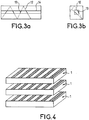
- An example of such a structure is given to the figure 4 such a structure can be used with or without coupling optics.
- the dimension of the concentrator 5 corresponding to the width of the laser bar in the parallel plane D ⁇ is for example equal to 1.5 mm.
- the thickness e c of the light concentrator is substantially constant and equal to 1.5 mm.
- the outlet face of the concentrator has a square cross section s c substantially equal to 1.5 * 1.5 mm 2 .
- the active laser medium 3 is formed for example of a composite bar comprising a doped central zone 8 having a parallelepipedal shape of square section s, for example, surrounded by an undoped peripheral zone 9 that is to say not having practically no dopant see no dopant.
- the dopant used for the active medium is chosen for example from one or more of the ions of the following list: (Nd 3+ , Yb 3+ , Er 3+ , Ho 3+ , Th 3+ , .).
- the active laser medium is for example a solid medium having one or more laser transitions (YAG: Nd, YVO 4 : Nd, sapphire: Ti, etc.) and known to those skilled in the art.
- the doped zone 8 has a length L d substantially equal to the length L 1 of the active laser medium, a section s d , and a volume V d corresponding to s d * L d .
- the pump lumen is deposited or absorbed in this volume V d according to, for example, the diagram described in Figures 3a and 3b .
- the doped zone 8 has dimensions adapted to the fundamental mode of the laser cavity for example. They can also be fixed to favor the appearance of other transverse modes. Its length is for example chosen according to the amount of light to be deposited and the absorption.
- the dimensions of the doped zone are chosen as a function of the fundamental mode dimensions of the laser cavity.
- the section s d of the doped zone is preferably less than or equal to the section s m of the fundamental mode of the cavity. She can also be slightly greater or greater than the fundamental mode section and associated with another selection device.
- the section s m of the fundamental mode corresponds for example to the section of the laser beam taken at about 13.6% of the maximum.
- the interface between the doped zone 8 and the peripheral zone 9 will be made in such a way as to minimize the losses likely to hinder or deteriorate the operation of the laser, according to techniques known to those skilled in the art.
- the dimensions of the peripheral zone 9 are chosen for example according to the performance of the focusing optics, for example the focusing spot, the divergence of the radiation after the focusing point.
- the section S nd and S d is substantially equal to the section S c of the facing face of the concentrator.
- the length L nd of the undoped zone corresponds for example to the length of the material or active medium forming the laser. It can correspond to the length L d of the doped zone.
- the doping can also be obtained in the form of a gradient of dopants distributed in a non-homogeneous manner in the material forming the active medium.
- the gradient, the distribution of the dopants and their nature will be determined according to the mode of operation selected for the laser.
- the bar comprises at least one of its ends a totally undoped section.
- This technique makes it possible to reduce the deformations at the ends of a bar.
- the contact between the undoped sections and the non-homogeneously doped sections may be achieved by a bonding diffusion technique known to those skilled in the art.
- the two outer faces 10, 11 of the composite bar are polished to guide the pump light by total or substantially total reflection.
- the face 10 of the composite bar facing the concentrator 5 is treated by means of an antireflection treatment to the length pumping wave and to be totally reflective at the laser wavelength.
- the opposite face 11 of the bar is treated using an antireflection treatment at the laser wavelength.
- This face can be polished inclined so that the beam has an angle of incidence value close to the Brewster value.
- the Figures 3a and 3b schematically an example of a path of the pump light in the active laser medium having a central doped zone of parallelepiped shape as represented on the figure 2 .
- the laser beam does not necessarily pass through the undoped zone at each reflection.
- the power of the pump is deposited only in the doped central zone which favors TEM 00 operation .
- such a structure makes it possible to overcome the divergence of the pump light incident on the composite medium.
- the pump lumen is guided by reflection on the lateral faces of the laser medium, total internal reflection or on a dielectric treatment and also performs a zigzag path in the composite bar by depositing energy only in the doped zone 8. After a sufficient number of reflections all the power of the pump will be absorbed.
- the geometry (shape and dimensions) of the undoped zone is adapted to optimize the number of beams passing through it while providing guidance in total reflection.
- the pump power is distributed in a larger volume than the volume usually offered by the lasers of the prior art, which makes it possible in particular to reduce aberrations, stresses, and birefringences. of thermal origin.
- the active medium comprises an undoped central zone and a doped peripheral zone.
- the light path will deposit energy not centrally but at the periphery of the composite bar, thus favoring higher order modes.
- This arrangement favors the mode usually called crown.
- the doped zone is off-center with respect to the zone which guides the pump or else the guiding zone has a particular shape, for example in the form of a D.
- One way of producing a non-homogeneously doped composite bar comprises, for example, steps for assembling doped or undoped discrete pieces of a matrix that have been polished before assembly.
- the matrix is for example chosen from the following list: YAG, YLF, YVO 4 , GdCOB, glass.
- the latter have the advantage of producing a preform with a doped part and an undoped preform portion of index jump fiber or a preform with a progressive transition between the doped zone and the undoped zone such as the fiber preform. index gradient.
- the dopants are distributed in the form of a gradient inside the doped zone.
- This preform can be drawn to make its diameter compatible with the dimensions necessary for this application.
- the matrix is for example glass of different compositions such as silicate, phosphate, fluorinated or any other material for which the drawing technique is suitable.
- Such a technique makes it possible in particular to produce doped zones of circular section which is particularly well adapted to the section of the fundamental modes of the cavity.
- extension or redistribution systems of the geometrical extent of the beam for example as shown in FIG. figure 5 .
- the laser according to the invention can also be used as an amplifier of a laser beam.
- the figure 6 schematizes an embodiment of use of a structure comprising a non-uniformly doped bar as described in FIG. figure 2 for amplifying a laser beam from a laser source.
- the incident laser beam 20 penetrates with an angle other than zero into the amplifying structure 21 and leaves it for example with a direction substantially parallel to the incident direction in the form of an amplified laser beam 22.
- the angle of incidence must be small so that the beam passes through all or at least the majority of the doped zone.
- the section of the beam may be slightly smaller than the section of the doped zone.
- the dimensions of the doped and undoped zones are chosen to increase the energy of the incident beam while retaining the laser mode, for example the TEM 00 mode.
- Such a use advantageously makes it possible to increase the energy of the beam while maintaining the operating mode TEM 00 .
- the amplified laser beam may be a laser beam from a femtosecond laser.
- the laser structure according to the invention can also be used as a regenerative amplifier, an embodiment of which is given to the figure 7 .
- a laser beam F e to be amplified arrives on a polarizer 30 adapted to transmit all (100%) or at least a majority of such a device such as a Pockels cell 31 acting in particular as a blade to phase delay and known to man from job.
- the beam F e has, for example, a linear polarization. It emerges from this cell with a circular polarization before being transmitted to block 32 comprising the elements described in FIG. figure 2 , in particular the non-homogeneously doped laser medium, the mirror 6 being replaced by a cavity-bottom mirror 33 disposed after the polarizer.
- F 1 is reflected on the face 10 of the non-uniformly doped rod and emerges by the face 11.
- the beam F 1 is thus trapped in the structure comprising the block 32 and the mirror 33 the Pockels cell allowing it to enter and exit. He thus makes several round trips during which he acquires energy, and is thus amplified.
- the value of the gain G obtained depends in particular on the number of round trips made and the structure of the bar doped non-homogeneously.
- the Pockels cell makes it possible to extract it, the output beam F s being equal to G * F e .
- the device when it is used as an amplifier of a laser beam comprises at least the following elements: a light source whose function is notably to excite a laser medium, a device for coupling the beam of light coming from the source to the laser medium.
- the laser medium used comprises a doped zone and an undoped zone at least, having one of the characteristics stated in connection with the figure 2 in order to increase the power energy of a laser beam to be amplified.
Description
L'invention concerne les lasers pompés et les milieux lasers optimisés.The invention relates to pumped lasers and optimized laser media.
Elle s'applique plus particulièrement aux lasers pompés diode, par exemple un laser pompé diode comportant une optique de couplage simple.It applies more particularly to diode pumped lasers, for example a pumped diode laser comprising a simple coupling optics.
Elle peut aussi être utilisée comme un amplificateur de faisceaux de type lasers.It can also be used as a laser beam amplifier.
La géométrie de pompage des lasers pompés par lampe est quasiment exclusivement une géométrie de pompage dite transversale, c'est-à-dire que la direction de propagation du faisceau dans la cavité optique et la plus grande dimension des lampes sont parallèles. La lumière émise par les lampes pénètre dans le milieu laser par ses faces transverses.The pump geometry of lamp-pumped lasers is almost exclusively a so-called transverse pumping geometry, that is to say that the direction of propagation of the beam in the optical cavity and the largest dimension of the lamps are parallel. The light emitted by the lamps penetrates the laser medium by its transverse faces.
Les diodes lasers dont l'émission est plus directive que celle d'une lampe permettent d'envisager une autre géométrie de pompage dite longitudinale. Le faisceau de pompe et le faisceau laser se propagent alors selon des directions voisines, le rendement du laser étant favorisé lorsque ces deux faisceaux se superposent avec des sections voisines dans le milieu laser. Il est aussi possible de favoriser un fonctionnement sur le mode fondamental TEM00 de la cavité stable lorsque la dimension du faisceau pompe est voisine de la dimension du mode fondamental.The laser diodes whose emission is more directive than that of a lamp make it possible to envisage another so-called longitudinal pumping geometry. The pump beam and the laser beam then propagate in adjacent directions, the efficiency of the laser being favored when these two beams are superimposed with neighboring sections in the laser medium. It is also possible to promote operation on the fundamental mode TEM 00 of the stable cavity when the size of the pump beam is close to the fundamental mode dimension.
Les faisceaux lasers fondamentaux des cavités stables ont des sections circulaires ou plus moins elliptiques qui ne coïncident pas nécessairement avec la forme des surfaces émissives des diodes lasers. Pour obtenir la superposition du faisceau pompe avec le faisceau du laser il est connu d'utiliser un système optique de focalisation ou de remise en forme de la lumière émise.The fundamental laser beams of stable cavities have circular or less elliptical sections which do not necessarily coincide with the shape of the emitting surfaces of the laser diodes. To obtain the superposition of the pump beam with the beam of the laser, it is known to use an optical focusing or reshaping system of the emitted light.
Par exemple, la réalisation d'un laser pompé longitudinalement nécessite l'emploi d'un système optique focalisant la lumière émise par une ou plusieurs barrettes de diodes laser de puissance.For example, the production of a laser pumped longitudinally requires the use of an optical system focusing the light emitted by one or more power laser diode arrays.
La
Compte tenu des caractéristiques actuelles des barrettes de puissance, la lumière émise peut être focalisée sur une tache de 1 à 2 mm environ de diamètre avec des rendements d'au moins 70 % (rapport entre la puissance moyenne transmise et la puissance moyenne émise).Given the current characteristics of the power strips, the light emitted can be focused on a spot of about 1 to 2 mm in diameter with yields of at least 70% (ratio of the average power transmitted and the average power emitted).
En sortie d'un tel système optique la lumière est très divergente ce qui est fâcheux car :
- le seuil d'oscillation du laser augmente avec le volume dans lequel l'énergie de pompe est déposée, et
- un fonctionnement multimode peut être induit si ce volume est plus grand que le volume occupé par le mode fondamental de la cavité.
- the oscillation threshold of the laser increases with the volume in which the pump energy is deposited, and
- multimode operation can be induced if this volume is larger than the volume occupied by the fundamental mode of the cavity.
Il est connu pour diminuer ces phénomènes d'utiliser des cristaux fortement dopés, le volume nécessaire pour absorber la puissance de pompe diminuant lorsque le coefficient d'absorption augmente. Cette solution présente néanmoins certains inconvénients, par exemple :
- favoriser l'apparition d'aberrations, de contraintes et de biréfringences d'origine thermique, la correction de ces effets devient difficile et le mode de fonctionnement en mode TEM00 n'est plus possible,
- réduire l'énergie de pompe susceptible d'être déposée sans atteindre le seuil d'endommagement du matériau, et
- limiter le choix des matériaux lasers.
- to favor the appearance of aberrations, constraints and birefringences of thermal origin, the correction of these effects becomes difficult and the mode of operation in TEM 00 mode is no longer possible,
- reduce the pump energy that can be deposited without reaching the damage threshold of the material, and
- limit the choice of laser materials.
Il est aussi connu de l'art antérieur d'utiliser des milieux lasers dopés de façon non homogène.It is also known from the prior art to use non-homogeneously doped laser media.
Par exemple, certains lasers ayant une géométrie de pompage transversale utilisent des milieux dopés non uniformément afin de sélectionner le mode souhaité.For example, some lasers with transverse pumping geometry use non-uniformly doped media to select the desired mode.
Dans d'autres applications, les barreaux lasers pompés longitudinalement ont une géométrie telle que la section du barreau est très petite devant la longueur utilisant le guidage de la lumière de pompe par réflexion totale sur la périphérie du barreau. Toutefois, la sélection de mode par le dopage n'est pas réalisée. Un exemple de réalisation est donné dans les références
L'idée de l'invention consiste, notamment, à utiliser comme milieu actif laser un matériau dopé de manière non homogène, comportant une ou plusieurs zones dans laquelle ou lesquelles, la distribution des dopants est notamment choisie en fonction d'un mode du laser favorisé, tel que le mode transversal souhaité.The idea of the invention consists, in particular, in using as a laser active medium a non-homogeneously doped material, comprising one or more zones in which the dopant distribution is chosen in particular according to a laser mode. favored, such as the desired transversal mode.
Elle repose aussi sur l'association d'un système optique de focalisation simple traitant de façon globale la source lumineuse issue de la diode avec le milieu actif laser non uniformément dopé.It is also based on the combination of a simple focusing optical system globally treating the light source from the diode with the non-uniformly doped laser active medium.
L'invention concerne un laser pompé longitudinalement comprenant un ou plusieurs milieux actifs lasers disposés dans une cavité optique et au moins un moyen de pompage émettant au moins un faisceau de pompe vers le ou les milieux actifs lasers, des moyens de couplage du ou des faisceaux de pompe avec le milieu actif. Il est caractérisé en ce qu'au moins un des milieux actifs lasers comporte une ou plusieurs zones dopées de façon non homogène et en ce que la dimension desdites zones dopées et/ou la répartition des dopants est choisie en fonction du mode transversal de la cavité laser souhaité.The invention relates to a laser pumped longitudinally comprising one or more active lasers media disposed in an optical cavity and at least one pumping means emitting at least one pump beam to the active medium or lasers, means for coupling the beam or beams pump with the active medium. It is characterized in that at least one of the active laser mediums comprises one or more non-homogeneously doped zones and in that the dimension of said doped zones and / or the dopant distribution is chosen as a function of the transverse mode of the cavity. desired laser.
La zone dopée est disposée par exemple de manière sensiblement centrale dans le milieu actif, ses dimensions sont adaptées au mode fondamental de la cavité laser ou au mode transversal et la zone périphérique non dopée a des dimensions adaptées au moyen de couplage.The doped zone is arranged for example substantially centrally in the active medium, its dimensions are adapted to the fundamental mode of the laser cavity or the transverse mode and the undoped peripheral zone has dimensions adapted to the coupling means.
La section sd de la face d'entrée de la zone dopée qui reçoit le faisceau de pompe est par exemple inférieure ou égale à la section sm du mode fondamental de la cavité.The section s d of the input face of the doped zone which receives the pump beam is for example less than or equal to the section s m of the fundamental mode of the cavity.
La section sd de la face d'entrée de la zone dopée qui reçoit le faisceau de pompe peut être au moins supérieure à la section sm du mode fondamental de la cavité, la cavité laser comportant un dispositif de sélection.The section s d of the input face of the doped zone which receives the pump beam may be at least greater than the section s m of the mode of the cavity, the laser cavity comprising a selection device.
Selon un autre mode de réalisation le milieu laser actif comporte une zone centrale non dopée entourée d'une zone périphérique dopée.According to another embodiment, the active laser medium comprises an undoped central zone surrounded by a doped peripheral zone.
La zone dopée a par exemple une forme parallélipipédique ou circulaire ou elliptique.The doped zone has for example a parallelepipedal or circular or elliptical shape.
Le ou les moyens de pompage peuvent comporter une ou plusieurs barrettes de diode et les moyens de couplage être constitués d'un concentrateur de lumière adapté à recevoir l'ensemble de la lumière émise par les barrettes de diodes.The pumping means may comprise one or more diode bars and the coupling means consist of a light concentrator adapted to receive all of the light emitted by the diode bars.
Les moyens de couplage comportent par exemple au moins un des dispositifs choisis dans la liste suivante : un système de focalisation par réfraction ou un système par diffraction ou un système par réflexion ou un système de remise en forme de l'étendue d'un faisceau.The coupling means comprise, for example, at least one of the devices chosen from the following list: a refractive focusing system or a diffraction system or a reflection system or a system for reshaping the extent of a beam.
La distribution des dopants dans le milieu actif est par exemple réalisée selon un gradient.The distribution of the dopants in the active medium is for example carried out according to a gradient.
Les dopants sont par exemple choisis parmi un ou plusieurs des ions de la liste suivante : (Nd3+, Yb3+, Er3+, Ho3+, Th3+,....).The dopants are for example chosen from one or more of the ions of the following list: (Nd 3+ , Yb 3+ , Er 3+ , Ho 3+ , Th 3+ , ....).
La face du milieu actif en regard du moyen de couplage est par exemple traitée anti-reflet à la longueur d'onde de pompage et réfléchissante à la longueur d'onde laser et la face du milieu actif à l'opposé est par exemple traitée antireflet à la longueur d'onde laser.The face of the active medium facing the coupling means is for example anti-reflective treated at the pumping wavelength and reflective at the laser wavelength and the face of the active medium opposite is for example anti-reflective treated. at the laser wavelength.
L'invention concerne aussi un procédé de fabrication d'un milieu actif utilisé dans les lasers. Il est caractérisé en ce qu'il comporte au moins une étape de réalisation d'un ou de plusieurs morceaux d'une matrice dopée et d'une matrice non dopée de façon à obtenir un milieu actif comportant une ou plusieurs zones ou volume ayant une dimension et/ou une répartition des dopants choisie pour obtenir un mode transversal de la cavité laser.The invention also relates to a method for manufacturing an active medium used in lasers. It is characterized in that it comprises at least one step of producing one or more pieces of a doped matrix and an undoped matrix in order to obtain an active medium comprising one or more zones or volume having a dimension and / or dopant distribution chosen to obtain a transverse mode of the laser cavity.
L'étape de réalisation peut être une étape d'assemblage réalisée par collage ou par adhérence moléculaire ou encore par diffusion bonding.The production step can be an assembly step performed by bonding or by molecular adhesion or by bonding diffusion.
Selon un autre mode de fabrication l'étape de réalisation est une étape de préforme de fibre à saut d'indice ou de préforme de fibre à gradient d'indice des dopants.According to another method of manufacture, the production step is a step of fiber preform with index jump or fiber preform with index gradient of the dopants.
Utilisation du laser présentant l'une des caractéristiques mentionnées précédemment pour amplifier un ou plusieurs faisceaux de type laser.Use of the laser having one of the features mentioned above for amplifying one or more laser-like beams.
Le laser selon l'invention présente notamment les avantages suivants :
- déposer la lumière de pompe dans un volume compatible avec un fonctionnement dans le mode fondamental (TEM00) et favoriser ce mode par rapport aux ordres supérieurs,
- réaliser un système de focalisation simple, indépendant de la structure de la barrette de laser (moyens de pompage) et potentiellement peu onéreux,
- s'affranchir du problème de la divergence de la lumière incidente sur le milieu laser sans avoir à utiliser des matériaux fortement dopés,
- déposer l'énergie de pompage dans un volume important en comparaison avec les lasers selon l'art antérieur et diminuer ainsi les aberrations optiques d'origine thermique, l'énergie se répartissant dans un volume plus important,
- ne pas dépasser le seuil de dommage (ou endommagement) du matériau laser malgré des puissances de pompe importantes,
- remove the pump light in a volume compatible with operation in the fundamental mode (TEM 00 ) and favor this mode with respect to higher orders,
- realize a simple focusing system, independent of the structure of the laser bar (pumping means) and potentially inexpensive,
- to overcome the problem of the divergence of the incident light on the laser medium without having to use heavily doped materials,
- depositing the pumping energy in a large volume in comparison with the lasers according to the prior art and thus reduce the optical aberrations of thermal origin, the energy being distributed in a larger volume,
- not to exceed the threshold of damage (or damage) of the laser material despite large pump powers,
D'autres avantages et caractéristiques de l'invention apparaîtront plus clairement dans la description faite à titre d'exemple nullement limitatif à la lecture des figures annexées où :
- la
figure 1 représente un exemple de diode laser selon l'art antérieur, - la
figure 2 est un schéma d'un exemple d'architecture d'un laser selon l'invention, - les
figures 3a et 3b représentent la propagation d'un rayon lumineux dans le milieu actif dopé de manière non homogène, - la
figure 4 montre une variante de diode laser de pompage, - la
figure 5 illustre deux exemples d'optique de couplage connues de l'Homme du métier, et - les
figures 6 et7 représentent deux exemples de schéma utilisant le laser selon l'invention comme amplificateur.
- the
figure 1 represents an example of a laser diode according to the prior art, - the
figure 2 is a diagram of an exemplary architecture of a laser according to the invention, - the
Figures 3a and 3b represent the propagation of a light ray in the non-homogeneously doped active medium, - the
figure 4 shows a variant of laser diode pumping, - the
figure 5 illustrates two examples of coupling optics known to those skilled in the art, and - the
figures 6 and7 represent two examples of a diagram using the laser according to the invention as an amplifier.
De manière à mieux faire comprendre le principe de fonctionnement du laser selon l'invention, la description qui suit à titre d'exemple illustratif et nullement limitatif concerne un laser pompé diode associé à l'aide d'une optique de couplage simple à un milieu laser actif dopé non-uniformément afin notamment de privilégier le mode transversal TEM00 de la cavité laser.In order to better understand the operating principle of the laser according to the invention, the following description by way of illustrative and non-limiting example relates to a diode pumped laser associated with a simple coupling optics to a medium non-uniformly doped active laser, in particular to favor the TEM 00 transverse mode of the laser cavity.
La
Le miroir 6 est par exemple disposé dans l'axe optique du laser, perpendiculairement au faisceau laser. Il présente des caractéristiques de transmission adaptées pour optimiser le fonctionnement du laser.The mirror 6 is for example disposed in the optical axis of the laser, perpendicular to the laser beam. It has transmission characteristics adapted to optimize the operation of the laser.
La diode laser de pompage 4 peut être une diode laser unitaire, ou un assemblage de diodes laser (barrettes, empilement de barrettes, plaques à émission par la surface,....) tel que décrit par exemple à la
La diode laser peut aussi se présenter sous une forme de plusieurs barrettes disposées de façon telle que l'émission ait lieu dans les trois dimensions. Un exemple d'une telle structure est donné à la
Les moyens de couplage 5 sont adaptés au type de la diode laser de pompage utilisée. Pou un pompage de type longitudinal, il est par exemple possible d'utiliser un concentrateur de lumière tel que décrit dans une des références suivantes :
- [1] le document ayant pour titre " High efficiency TEM00 Nd :YVO4 laser longitudinally pumped by a high power laser diode array ", SPIE Proceeding,
- [2] le document ayant pour titre "
Nonimaging optics III : Maximum Efficiency Light Transfer ", 1995 ayant pour auteurs G.Feugnet, C.Bussac, M.Schwartz, C.Larat et J.P Pocholle ou publié dans la revue Opt.Lett.20, pp 157-159 en 1995
- [1] the document entitled "High efficiency TEM 00 Nd: YVO 4 laser longitudinally pumped by a high power laser diode array", SPIE Proceeding,
- [2] the document entitled "
Nonimaging optics III: Maximum Efficiency Light Transfer ", 1995 by G.Feugnet, C.Bussac, M.Schwartz, C.Larat and JP Pocholle or published in the journal Opt.Lett.20, pp 157-159 in 1995
La dimension du concentrateur 5 correspondant à la largeur du barreau laser dans le plan parallèle D ∥ est par exemple égale à 1,5 mm. L'épaisseur ec du concentrateur de lumière est sensiblement constante et égale à 1,5 mm. La face de sortie du concentrateur a une section carrée sc sensiblement égale à 1,5*1,5 mm2.The dimension of the
Le milieu laser actif 3 est formé par exemple d'un barreau composite comportant une zone centrale 8 dopée ayant une forme parallélipipédique de section sd carrée, par exemple, entourée d'une zone périphérique 9 non dopée c'est-à-dire ne comportant pratiquement pas de dopant voir aucun dopant.The
Le dopant utilisé pour le milieu actif est choisi par exemple parmi un ou plusieurs des ions de la liste suivante : (Nd3+, Yb3+, Er3+, Ho3+, Th3+,....).The dopant used for the active medium is chosen for example from one or more of the ions of the following list: (Nd 3+ , Yb 3+ , Er 3+ , Ho 3+ , Th 3+ , ....).
Le milieu laser actif est par exemple un milieu solide présentant une ou plusieurs transitions laser (YAG :Nd, YVO4 :Nd, saphir :Ti, etc) et connu de l'Homme du métier.The active laser medium is for example a solid medium having one or more laser transitions (YAG: Nd, YVO 4 : Nd, sapphire: Ti, etc.) and known to those skilled in the art.
La zone dopée 8 possède une longueur Ld sensiblement égale à la longueur Ll du milieu laser actif, une section sd, et un volume Vd correspondant à sd * Ld. La lumière de pompe est déposée ou absorbée dans ce volume Vd selon par exemple le schéma décrit aux
La zone dopée 8 a des dimensions adaptées au mode fondamental de la cavité laser par exemple. Elles peuvent aussi être fixées pour favoriser l'apparition d'autres modes transverses. Sa longueur est par exemple choisie en fonction de la quantité de lumière à déposer et de l'absorption.The doped
Une manière pour déterminer la géométrie et les dimensions de la zone dopée non uniformément et/ou la distribution des dopants comporte par exemple les étapes suivantes :
- A partir des caractéristiques de la source émissive (diode laser) telles que ses dimensions, ses divergences....concevoir une optique de focalisation. L'optique de focalisation est déterminée par exemple pour avoir une transmission aussi bonne que possible, selon des critères connus de l'Homme du métier. Typiquement, la lumière est focalisée sur une tache dont la section sl est de quelques millimètres carrés,

- Adapter la section du barreau non uniformément dopé aux dimensions de la tache de la lumière.
- Par exemple, la section du barreau peut être sensiblement carrée, égale ou légèrement plus grande que celle de la face de sortie du concentrateur,
- Pour un barreau cylindrique, le diamètre est sensiblement égal ou légèrement supérieur à la diagonale de la face de sortie du concentrateur,
- Les dimensions peuvent aussi être choisies pour tenir compte des tolérances de positionnement du barreau devant le concentrateur et la qualité des arêtes du barreau.
- Dans le cas d'une focalisation utilisant une lentille, la section du barreau est adaptée pour que la transmission T à travers une ouverture fictive de dimensions identiques soit de l'ordre de 100%

-
- Le rapport r entre les dimensions de la zone dopée et celles de la zone non dopée est défini en tenant compte des caractéristiques du rayonnement de pompe prises après l'optique de couplage 5, des caractéristiques spectroscopiques du matériau laser et des contraintes technologiques liées à la réalisation du barreau non uniformément dopé. Les caractéristiques spectroscopiques du matériau laser peuvent être enregistrées au cours d'essais préalables par des méthodes connues de l'Homme du métier.
- Le processus de détermination du rapport r se déroule par exemple de manière itérative, et comporte par exemple les étapes suivantes :
- au cours d'une première étape a), fixer la valeur du rapport r à une valeur r0,
- calculer (deuxième étape b)) la répartition d'énergie de pompe dans le barreau et les effets thermiques associés à partir de cette valeur, en mettant en oeuvre un programme de tracé de rayon et un programme de calculs thermiques,
- au cours d'une troisième étape c), concevoir une cavité laser dont le mode TEM00 est proche des dimensions de la zone dopée par exemple à l'aide d'un programme de calcul de cavité laser prenant en compte les effets thermiques,
- si le mode TEM00 déterminé est différent ou trop éloigné, changer la valeur du ratio choisie initialement et recommencer les étapes a) à c). La valeur de la longueur de la cavité laser peut en effet être limitée pour des raisons d'encombrement.
-
- From the characteristics of the emissive source (laser diode) such as its dimensions, its divergences .... to design a focusing optics. The focusing optics is determined for example to have a transmission as good as possible, according to criteria known to those skilled in the art. Typically the light is focused on a spot which is the section s of a few square millimeters,
- Adapt the non-uniformly doped section of the bar to the dimensions of the spot of light.
- For example, the section of the bar may be substantially square, equal to or slightly larger than that of the outlet face of the concentrator,
- For a cylindrical bar, the diameter is substantially equal to or slightly greater than the diagonal of the outlet face of the concentrator,
- The dimensions can also be chosen to take into account the positioning tolerances of the bar in front of the concentrator and the quality of the edges of the bar.
- In the case of focusing using a lens, the section of the bar is adapted so that the transmission T through a fictitious opening of identical dimensions is of the order of 100%
-
- The ratio r between the dimensions of the doped zone and those of the undoped zone is defined taking into account the characteristics of the pump radiation taken after the
coupling optics 5, the spectroscopic characteristics of the laser material and the technological constraints related to the realization of the bar not uniformly doped. The spectroscopic characteristics of the laser material may be recorded during prior tests by methods known to those skilled in the art. - The process for determining the ratio r takes place, for example, iteratively, and comprises, for example, the following steps:
- in a first step a), set the value of the ratio r to a value r 0 ,
- calculating (second step b)) the distribution of pump energy in the bar and the associated thermal effects from this value, by implementing a ray tracing program and a thermal calculation program,
- during a third step c), designing a laser cavity whose TEM 00 mode is close to the dimensions of the doped zone, for example using a laser cavity calculation program taking into account the thermal effects,
- if the determined TEM 00 mode is different or too far, change the value of the initially selected ratio and repeat steps a) to c). The value of the length of the laser cavity can in fact be limited for reasons of space.
-
Lors de la détermination de la valeur du rapport r, il est nécessaire de tenir compte des contraintes suivantes :
- l'influence de sa valeur sur la longueur du barreau nécessaire pour absorber l'énergie sachant que cette longueur peut être limitée pour des raisons de technologie,
- l'influence de sa valeur sur l'énergie absorbée par unité de longueur qui doit demeurer largement inférieur au seuil de dommage optique.
- the influence of its value on the length of the bar necessary to absorb the energy knowing that this length can be limited for reasons of technology,
- the influence of its value on the absorbed energy per unit of length which must remain well below the threshold of optical damage.
Pour obtenir une bonne discrimination entre le mode fondamental de la cavité et les modes d'ordre supérieurs, favorisant ainsi le fonctionnement TEM00, les dimensions de la zone dopée sont choisies en fonction des dimensions du mode fondamental de la cavité laser.In order to obtain a good discrimination between the fundamental mode of the cavity and the higher order modes, thus favoring the TEM 00 operation , the dimensions of the doped zone are chosen as a function of the fundamental mode dimensions of the laser cavity.
Ainsi, la section sd de la zone dopée est de préférence inférieure ou égale à la section sm du mode fondamental de la cavité. Elle peut aussi être légèrement supérieure ou supérieure à la section du mode fondamental et associée à un autre dispositif de sélection.Thus, the section s d of the doped zone is preferably less than or equal to the section s m of the fundamental mode of the cavity. She can also be slightly greater or greater than the fundamental mode section and associated with another selection device.
La section sm du mode fondamental correspond par exemple à la section du faisceau laser prise à environ 13,6 % du maximum.The section s m of the fundamental mode corresponds for example to the section of the laser beam taken at about 13.6% of the maximum.
Les étapes décrites en relation avec une géométrie carrée peuvent aussi être appliquée dans le cas d'une géométrie cylindrique, en considérant dans ce cas la section cylindre de la zone dopée.The steps described in relation to a square geometry can also be applied in the case of a cylindrical geometry, considering in this case the cylinder section of the doped zone.
L'interface entre la zone dopée 8 et la zone périphérique 9 sera réalisée de manière à minimiser les pertes susceptibles de gêner ou de détériorer le fonctionnement du laser, selon des techniques connues de l'Homme du métier.The interface between the doped
Les dimensions de la zone périphérique 9 sont choisies par exemple en fonction des performances de l'optique de focalisation, par exemple la tache de focalisation, la divergence du rayonnement après le point de focalisation. La section Snd et Sd est sensiblement égale à la section Sc de la face du concentrateur disposée en regard. La longueur Lnd de la zone non dopée correspond par exemple à la longueur du matériau ou milieu actif formant le laser. Elle peut correspondre à la longueur Ld de la zone dopée.The dimensions of the
Sans sortir du cadre de l'invention, le dopage peut aussi être obtenu sous la forme d'un gradient de dopants répartis de manière non homogène dans le matériau formant le milieu actif. Le gradient, la répartition des dopants ainsi que leur nature seront déterminés en fonction du mode de fonctionnement retenu pour le laser.Without departing from the scope of the invention, the doping can also be obtained in the form of a gradient of dopants distributed in a non-homogeneous manner in the material forming the active medium. The gradient, the distribution of the dopants and their nature will be determined according to the mode of operation selected for the laser.
Selon une autre variante de réalisation, le barreau comprend au moins à une de ses extrémités une section totalement non dopée. Cette technique permet de diminuer les déformations aux extrémités d'un barreau. Le contact entre les sections non dopées et les sections dopées de manière non homogène peut être réalisé par une technique de diffusion bonding connue de l'Homme du métier.According to another embodiment, the bar comprises at least one of its ends a totally undoped section. This technique makes it possible to reduce the deformations at the ends of a bar. The contact between the undoped sections and the non-homogeneously doped sections may be achieved by a bonding diffusion technique known to those skilled in the art.
Les deux faces externes 10, 11 du barreau composite sont polies pour guider la lumière de pompe par réflexion totale ou pratiquement totale.The two
La face 10 du barreau composite qui se trouve en regard du concentrateur 5 est traitée au moyen d'un traitement anti-reflet à la longueur d'onde de pompage et pour être totalement réfléchissante à la longueur d'onde laser.The
La face opposée 11 du barreau est traitée à l'aide d'un traitement anti-reflet à la longueur d'onde laser. Cette face peut être polie inclinée afin que le faisceau ait une valeur d'angle d'incidence proche de la valeur de Brewster. Lors du montage du barreau laser les précautions nécessaires habituelles seront prises pour éviter qu'une partie du faisceau ne se propage dans un autre milieu accolé.The
Les
Ainsi, sur les trajets 12 en pointillés il n'y pas d'absorption de lumière alors que sur les trajets 13 des rayons lumineux représentés en traits pleins le rayon lumineux est absorbé. La lumière de pompe est guidée par réflexion sur les faces latérales du milieu laser, réflexion totale interne ou sur un traitement diélectrique et effectue aussi un trajet en zigzag dans le barreau composite en déposant de l'énergie uniquement dans la zone dopée 8. Après un nombre suffisant de réflexions toute la puissance de la pompe sera absorbée.Thus, on the
La géométrie (forme et dimensions) de la zone non dopée est adaptée pour optimiser le nombre de faisceaux la traversant tout en assurant un guidage en réflexion totale.The geometry (shape and dimensions) of the undoped zone is adapted to optimize the number of beams passing through it while providing guidance in total reflection.
En comparaison avec les structures à dopage élevé précitées, la puissance de pompe se trouve répartie dans un volume plus grand que le volume habituellement offert par les lasers de l'art antérieur, ce qui permet notamment de réduire les aberrations, les contraintes, les biréfringences d'origine thermique.In comparison with the aforementioned high-doped structures, the pump power is distributed in a larger volume than the volume usually offered by the lasers of the prior art, which makes it possible in particular to reduce aberrations, stresses, and birefringences. of thermal origin.
Selon une autre variante de réalisation, le milieu actif comporte une zone centrale non dopée et une zone périphérique dopée. Dans ce cas, le trajet lumineux va déposer de l'énergie non plus de façon centrale mais à la périphérie du barreau de composite, favorisant ainsi les modes d'ordre supérieurs. Cet agencement favorise le mode habituellement appelé en couronne.According to another variant embodiment, the active medium comprises an undoped central zone and a doped peripheral zone. In this case, the light path will deposit energy not centrally but at the periphery of the composite bar, thus favoring higher order modes. This arrangement favors the mode usually called crown.
Selon une autre variante, connue par exemple dans le domaine des fibres dites "double clad", technique décrite par exemple dans le brevet
Ces modes de réalisation qui consistent à casser la symétrie du milieu optimisé permettent de diminuer le nombre de rayons lumineux (ou de modes de propagation pour les fibres) qui ne pénètrent jamais dans la zone dopée et ne sont pas absorbés. L'absorption est ainsi augmentée.These embodiments of breaking the symmetry of the optimized medium reduce the number of light rays (or modes of propagation for the fibers) that never enter the doped area and are not absorbed. The absorption is thus increased.
Plusieurs procédés de fabrication peuvent être mis en oeuvre pour réaliser le milieu laser actif.Several manufacturing processes can be implemented to produce the active laser medium.
Une façon de fabriquer un barreau composite dopé de manière non homogène comporte par exemple des étapes d'assemblage de morceaux discrets dopés ou non dopées d'une matrice qui auront été polis avant assemblage.One way of producing a non-homogeneously doped composite bar comprises, for example, steps for assembling doped or undoped discrete pieces of a matrix that have been polished before assembly.
La matrice est par exemple choisie parmi la liste suivante : YAG, YLF, YVO4, GdCOB, verre.The matrix is for example chosen from the following list: YAG, YLF, YVO 4 , GdCOB, glass.
Les différents morceaux sont assemblés selon la géométrie de dopage souhaitée, par exemple :
- par collage avec une colle d'indice adapté, telle qu'une colle optique connue de l'Homme du métier,
- par adhérence moléculaire,
- par diffusion bonding ou soudure par interdiffusion aux interfaces entre les morceaux. Cette technique offre notamment une résistance importante aux chocs et de faibles pertes aux interfaces.
- by bonding with a glue of suitable index, such as an optical adhesive known to those skilled in the art,
- by molecular adhesion,
- by bonding diffusion or interdiffusion welding at the interfaces between the pieces. This technique offers in particular a significant resistance to shocks and low losses at the interfaces.
Une autre manière de procéder reposer sur l'utilisation de techniques utilisées dans les fibres optiques et connues de l'Homme du métier. Ces dernières présentent comme avantage de réaliser une préforme avec une partie dopée et une partie non dopée préforme de fibre à saut d'indice ou encore une préforme avec une transition progressive entre la zone dopée et la zone non dopée telle que la préforme de fibre à gradient d'indice. Les dopants sont distribués sous la forme d'un gradient à l'intérieur de la zone dopée.Another way to proceed based on the use of techniques used in optical fibers and known to man of the job. The latter have the advantage of producing a preform with a doped part and an undoped preform portion of index jump fiber or a preform with a progressive transition between the doped zone and the undoped zone such as the fiber preform. index gradient. The dopants are distributed in the form of a gradient inside the doped zone.
Cette préforme peut être tirée pour rendre son diamètre compatible avec les dimensions nécessaires pour cette application. La matrice est par exemple du verre de différentes compositions tel que silicate, phosphate, fluoré ou tout autre matériau pour lequel la technique de tirage est adaptée.This preform can be drawn to make its diameter compatible with the dimensions necessary for this application. The matrix is for example glass of different compositions such as silicate, phosphate, fluorinated or any other material for which the drawing technique is suitable.
Une telle technique permet notamment de réaliser des zones dopées de section circulaire particulièrement bien adaptée à la section des modes fondamentaux de la cavité.Such a technique makes it possible in particular to produce doped zones of circular section which is particularly well adapted to the section of the fundamental modes of the cavity.
Dans les différentes applications de l'ensemble laser comportant un laser pompé diode avec un milieu laser selon l'invention, différents moyens de focalisation peuvent être utilisésIn the various applications of the laser assembly comprising a pumped laser diode with a laser medium according to the invention, different focusing means can be used
Pour réaliser la fonction de focalisation deux approches peuvent être distinguées :
- Une première approche consiste à prendre en compte la nature discontinue de la source lumineuse et à imager chacune des diodes de la barrette. Des systèmes à base de faisceaux de fibres optiques, par injection optique dans une ou plusieurs fibres optiques, d'optiques réfractives telles que des lentilles, des lentilles cylindriques, d'optiques diffractives par exemple des lentilles holographiques, des micro-lentilles, de système par réflexion par exemple des micro-miroirs ou encore toute combinaison de ces systèmes peut être utilisée. Ils permettent d'obtenir une focalisation de la lumière performante car les zones non émissives ne sont pas prises en compte. Ils sont utilisés plus particulièrement pour des barrettes comportant un faible nombre d'émetteurs.
- Une deuxième approche consiste par exemple à considérer la barrette dans sa globalité sans tenir compte de la nature discontinue de la source. Des systèmes à base de lentilles macroscopiques, de concentrateurs correspondent par exemple à cette approche. Ces systèmes présentent l'avantage d'être relativement simples à réaliser. Ils sont aussi utilisables quel que soit le nombre d'émetteurs et la source lumineuse est interchangeable.
- A first approach is to take into account the discontinuous nature of the light source and to image each of the diodes of the bar. Systems based on optical fiber bundles, by optical injection into one or more optical fibers, refractive optics such as lenses, cylindrical lenses, diffractive optics, for example holographic lenses, microlenses, system by reflection for example micro-mirrors or any combination of these systems can be used. They make it possible to obtain a focus of the efficient light because the non-emissive zones are not taken into account. They are used more particularly for bars having a small number of transmitters.
- A second approach is for example to consider the bar in its entirety without taking into account the discontinuous nature of the source. Systems based on macroscopic lenses, concentrators correspond for example to this approach. These systems have the advantage of being relatively simple to achieve. They are also usable whatever the number of transmitters and the light source is interchangeable.
Il est aussi possible d'utiliser des systèmes de redistribution d'étendue ou de remise en forme de l'étendue géométrique du faisceau, par exemple tel que représentés à la
Sans sortir du cadre de l'invention, le laser selon l'invention peut aussi être utilisé comme amplificateur d'un faisceau laser.Without departing from the scope of the invention, the laser according to the invention can also be used as an amplifier of a laser beam.
La
Le faisceau laser incident 20 pénètre avec un angle différent de zéro dans la structure amplificatrice 21 et en ressort par exemple avec une direction sensiblement parallèle à la direction incidente sous la forme d'un faisceau laser amplifié 22.The
L'angle d'incidence doit être faible pour que le faisceau traverse la totalité ou au moins la majorité de la zone dopée. La section du faisceau peut être légèrement inférieure à la section de la zone dopée.The angle of incidence must be small so that the beam passes through all or at least the majority of the doped zone. The section of the beam may be slightly smaller than the section of the doped zone.
Les dimensions des zones dopées et non dopées sont choisies pour augmenter l'énergie du faisceau incident tout en conservant le mode laser, par exemple le mode TEM00.The dimensions of the doped and undoped zones are chosen to increase the energy of the incident beam while retaining the laser mode, for example the TEM 00 mode.
Une telle utilisation permet avantageusement d'augmenter l'énergie du faisceau tout en conservant le mode de fonctionnement TEM00.Such a use advantageously makes it possible to increase the energy of the beam while maintaining the operating mode TEM 00 .
Le faisceau laser amplifié peut être un faisceau laser issu d'un laser femtosecondes.The amplified laser beam may be a laser beam from a femtosecond laser.
La structure de laser selon l'invention peut aussi être utilisée comme un amplificateur régénératif dont un exemple de réalisation est donné à la
Sur cet exemple de réalisation, un faisceau laser Fe à amplifier arrive sur un polariseur 30 adapté pour le transmettre en totalité (100%) ou au moins en majorité à un dispositif tel qu'une cellule de Pockels 31 agissant notamment comme une lame à retard de phase et connue de l'Homme du métier. En entrée de cellule de Pockels le faisceau Fe possède par exemple une polarisation linéaire. Il ressort de cette cellule avec une polarisation circulaire avant d'être transmis au bloc 32 comportant les éléments décrits à la
Lorsque le faisceau F1 a acquis le gain souhaité, la cellule de Pockels permet de l'extraire, le faisceau de sortie Fs étant égal à G*Fe.When the beam F 1 has acquired the desired gain, the Pockels cell makes it possible to extract it, the output beam F s being equal to G * F e .
Le fonctionnement d'une cellule de Pockels étant connu de l'Homme du métier, il n'a pas été détaillé.The operation of a Pockels cell being known to those skilled in the art, it has not been detailed.
De manière générale, le dispositif lorsqu'il est utilisé comme amplificateur d'un faisceau laser comporte au moins les éléments suivants : une source lumineuse ayant pour fonction notamment d'exciter un milieu laser, un dispositif de couplage du faisceau de lumière issu de la source vers le milieu laser. Le milieu laser utilisé comporte une zone dopée et une zone non dopée au moins, présentant l'une des caractéristiques énoncées en relation avec la
Claims (11)
- Laser suitable for being longitudinally pumped comprising one or more active lasing media in the form of a composite rod, arranged in an optical cavity and at least one pumping means (4) emitting at least one pumping beam toward the active lasing medium or media (3), means (5) for the coupling of the pumped beam or beams with the active medium, characterised in that at least one of the active lasing media comprises one or more non-doped zones (9) that are contiguous to one or more non-homogeneously doped zones (8) and in that the dimension of said doped zones (8) and/or the distribution of the dopants is chosen on the basis of the desired transverse mode of the laser cavity so as to ensure a discrimination between the fundamental mode of the cavity and the higher-order modes.
- Laser according to claim 1, characterised in that the doped zone (8) is positioned substantially centrally in the active medium (3), its dimensions are adapted to the fundamental mode of the laser cavity or to the transverse mode and in that the non-doped peripheral zone has dimensions adapted to the coupling means (5).
- Laser according to one of the claims 1 or 2, characterised in that the square or circular section sd of the input face of the doped zone that receives the pump beam is smaller than or equal to the circular or elliptical section sm of the fundamental mode of the cavity.
- Laser according to claim 1, characterised in that the active medium (3) comprises a non-doped central zone surrounded by a doped peripheral zone.
- Laser according to one of the preceding claims, characterised in that the doped zone has a parallelepiped or circular or elliptical shape.
- Laser according to one of the claims 1 to 5, characterised in that said one or more pumping means (4) comprise one or more diode arrays and in that the coupling means (5) consist of a light concentrator adapted to receiving all the light emitted by said diode arrays.
- Laser according to one of the claims 1 to 5, characterised in that said coupling means comprise at least one of the devices chosen from the following list: a refractive focusing system or a system working by diffraction or a system working by reflection or a system for reshaping the extent of a beam.
- Laser according to claim 1, characterised in that the distribution of the dopants in the active medium is made according to a gradient.
- Laser according to one of the preceding claims, characterised in that the dopants are chosen from among one or more of the ions of the following list: (Nd3+, Yb3+, Er3+, Ho3+, Th3+, ...).
- Laser according to one of the preceding claims, characterised in that the face of the active medium facing the coupling means is treated so as to be anti-reflective at the pumping wavelength and reflective at the laser wavelength, and in that the opposite face of the active medium is treated so as to be anti-reflective at the laser wavelength.
- Method for the manufacture of an active medium of a laser according to claim 1, characterised in that it comprises at least one step for the making of one or more pieces of a non-homogeneously doped matrix and a non-doped matrix so as to obtain an active medium comprising one or more zones or volumes having a dimension and/or a nonhomogeneous distribution of the dopants chosen to obtain a transverse mode of the laser cavity.
Applications Claiming Priority (3)
| Application Number | Priority Date | Filing Date | Title |
|---|---|---|---|
| FR0008519A FR2811148B1 (en) | 2000-06-30 | 2000-06-30 | PUMP LASER AND OPTIMIZED LASER MEDIA |
| FR0008519 | 2000-06-30 | ||
| PCT/FR2001/001813 WO2002001683A1 (en) | 2000-06-30 | 2001-06-12 | Pumped laser and optimised lasing medium |
Publications (2)
| Publication Number | Publication Date |
|---|---|
| EP1212814A1 EP1212814A1 (en) | 2002-06-12 |
| EP1212814B1 true EP1212814B1 (en) | 2019-05-01 |
Family
ID=8851964
Family Applications (1)
| Application Number | Title | Priority Date | Filing Date |
|---|---|---|---|
| EP01945399.2A Expired - Lifetime EP1212814B1 (en) | 2000-06-30 | 2001-06-12 | Pumped laser and optimised lasing medium |
Country Status (4)
| Country | Link |
|---|---|
| US (1) | US6961360B2 (en) |
| EP (1) | EP1212814B1 (en) |
| FR (1) | FR2811148B1 (en) |
| WO (1) | WO2002001683A1 (en) |
Families Citing this family (4)
| Publication number | Priority date | Publication date | Assignee | Title |
|---|---|---|---|---|
| JP2006261194A (en) * | 2005-03-15 | 2006-09-28 | Jtekt Corp | Fiber laser oscillator |
| DE102007033624B4 (en) * | 2007-07-17 | 2010-08-26 | Deutsch Französisches Forschungsinstitut Saint Louis | Heat capacity laser |
| CN105870772B (en) * | 2016-06-16 | 2018-11-23 | 中国工程物理研究院激光聚变研究中心 | A kind of laser gain chip and laser module, power amplifier and oscillator |
| CN112397977B (en) * | 2020-11-18 | 2022-03-04 | 中国科学院理化技术研究所 | Lath laser |
Citations (1)
| Publication number | Priority date | Publication date | Assignee | Title |
|---|---|---|---|---|
| JPH07321394A (en) * | 1994-05-23 | 1995-12-08 | Nec Corp | Crystal for solid state laser |
Family Cites Families (14)
| Publication number | Priority date | Publication date | Assignee | Title |
|---|---|---|---|---|
| FR2640438B1 (en) | 1988-12-09 | 1991-01-25 | Thomson Csf | PROCESS FOR PRODUCING SEMICONDUCTOR LASERS AND LASERS OBTAINED BY THE PROCESS |
| FR2647973B1 (en) | 1989-05-30 | 1991-08-16 | Thomson Csf | POWER LASERS PUMPS BY LASER DIODES |
| FR2648962B1 (en) | 1989-06-23 | 1994-09-09 | Thomson Csf | ILLUMINATION STRUCTURE OF A LASER BAR, WITH DEFOCALIZED OPTICAL SOURCES |
| FR2649548B1 (en) | 1989-07-06 | 1994-08-26 | Thomson Csf | SOLID EMITTING WAVELENGTH LASER 0.5-0.65 MICROMETERS |
| FR2649833A1 (en) | 1989-07-11 | 1991-01-18 | Thomson Csf | TUNABLE POWER SOURCE SOURCE |
| FR2652685B1 (en) | 1989-10-03 | 1991-12-06 | Thomson Csf | LASER POWER SOURCE WITH BEAM SCANNING OPTICAL CONTROL. |
| FR2655486B1 (en) | 1989-12-01 | 1994-08-26 | Thomson Csf | HIGH WAVELENGTH LASER DEVICE. |
| FR2666699A1 (en) | 1990-09-11 | 1992-03-13 | Thomson Csf | LASER WITH COUPLED OPTICAL GUIDES. |
| JPH05310440A (en) * | 1992-05-08 | 1993-11-22 | Matsushita Electric Ind Co Ltd | Optical fiber, optical amplifier, optical transmitting system and solid laser |
| FR2725081B1 (en) | 1994-09-23 | 1996-11-15 | Thomson Csf | COMPACT OPTICAL SOURCE, BASED ON THE FREQUENCY DOUBLING OF A LASER AND SELF-STABILIZED BY PUMP DEPOPE |
| US5877890A (en) * | 1996-10-30 | 1999-03-02 | Rutgers, The State University Of New Jersey | Optical-fiber amplifier having high-saturation output |
| DE19807891A1 (en) * | 1998-02-25 | 1999-08-26 | Abb Research Ltd | Fiber-laser sensor for measurement of elongation, temperature or especially isotropic pressure in oil well |
| US6418156B1 (en) * | 1998-11-12 | 2002-07-09 | Raytheon Company | Laser with gain medium configured to provide an integrated optical pump cavity |
| US6330388B1 (en) * | 1999-01-27 | 2001-12-11 | Northstar Photonics, Inc. | Method and apparatus for waveguide optics and devices |
-
2000
- 2000-06-30 FR FR0008519A patent/FR2811148B1/en not_active Expired - Lifetime
-
2001
- 2001-06-12 WO PCT/FR2001/001813 patent/WO2002001683A1/en active Application Filing
- 2001-06-12 US US10/069,599 patent/US6961360B2/en not_active Expired - Lifetime
- 2001-06-12 EP EP01945399.2A patent/EP1212814B1/en not_active Expired - Lifetime
Patent Citations (1)
| Publication number | Priority date | Publication date | Assignee | Title |
|---|---|---|---|---|
| JPH07321394A (en) * | 1994-05-23 | 1995-12-08 | Nec Corp | Crystal for solid state laser |
Also Published As
| Publication number | Publication date |
|---|---|
| FR2811148B1 (en) | 2006-07-21 |
| FR2811148A1 (en) | 2002-01-04 |
| WO2002001683A1 (en) | 2002-01-03 |
| US20020122448A1 (en) | 2002-09-05 |
| US6961360B2 (en) | 2005-11-01 |
| EP1212814A1 (en) | 2002-06-12 |
Similar Documents
| Publication | Publication Date | Title |
|---|---|---|
| EP1849029B1 (en) | Composite optical fibre for a laser- and pump-wave confinement laser and use thereof in lasers | |
| EP0724315B1 (en) | Microlaser cavity and its manufacturing method | |
| FR2784809A1 (en) | Optical power amplifier comprises mono-mode waveguide and outer multi-mode waveguide providing energy for optical pumping | |
| EP2147487B1 (en) | Pulsed microchip laser | |
| EP1717914B1 (en) | Active element for laser source and laser source comprising such active element | |
| EP1212814B1 (en) | Pumped laser and optimised lasing medium | |
| EP2823342A1 (en) | Device for converting the transverse spatial profile of intensity of a light beam, preferably using a microstructured optical fibre | |
| FR2765411A1 (en) | SOLID LASER DEVICE WITH SEMICONDUCTOR EXCITATION | |
| EP2041848B1 (en) | Fiber optic power laser device | |
| EP1220386B1 (en) | Laser source | |
| WO2007026084A1 (en) | Optical pumping device | |
| FR2781613A1 (en) | FREE SPACE LASER WITH SELF-ALIGNED FIBER OUTPUT | |
| WO2022128931A1 (en) | Laser beam amplification device | |
| FR2739732A1 (en) | OPTICAL AMPLIFICATION DEVICE | |
| FR2880736A1 (en) | Positive spherical aberration correction method for e.g. laser cavity, involves compensating positive spherical aberration utilizing negative spherical aberration optical device within laser cavity, where device is constituted of lens | |
| FR2826458A1 (en) | ACTIVE COUPLING ELEMENT FOR COUPLING A LIGHT SIGNAL TO AN OPTICAL COMPONENT WITH A WAVEGUIDE AND OPTICAL STRUCTURE USING SUCH AN ELEMENT | |
| WO2007083007A1 (en) | Method of correcting aberrations caused by thermal effects in a laser cavity | |
| EP1317033A2 (en) | Laser beam amplification through pumping of a non-linear medium and laser device comprising such an amplifier | |
| WO2005015698A1 (en) | Power laser source with high spectral finesse | |
| FR2815181A1 (en) | Guided propagation optical amplifier having doped flat spiral waveguide circular flat disc embedded with optical pump around outer periphery | |
| FR2754400A1 (en) | Fibre Optic Laser Drive method for Microlasers | |
| EP1433232A2 (en) | Laser source in guided optics | |
| FR2875018A1 (en) | Bragg grating laser and micro-lens laser combining device, has collimation micro-lenses placed between laser bar and Bragg grating whose index layers form specific angle with fiber rod`s longitudinal axis, and beam splitter at rod`s output |
Legal Events
| Date | Code | Title | Description |
|---|---|---|---|
| PUAI | Public reference made under article 153(3) epc to a published international application that has entered the european phase |
Free format text: ORIGINAL CODE: 0009012 |
|
| 17P | Request for examination filed |
Effective date: 20020326 |
|
| AK | Designated contracting states |
Kind code of ref document: A1 Designated state(s): AT BE CH CY DE DK ES FI FR GB GR IE IT LI LU MC NL PT SE TR |
|
| RBV | Designated contracting states (corrected) |
Designated state(s): DE |
|
| 17Q | First examination report despatched |
Effective date: 20100322 |
|
| GRAP | Despatch of communication of intention to grant a patent |
Free format text: ORIGINAL CODE: EPIDOSNIGR1 |
|
| INTG | Intention to grant announced |
Effective date: 20190103 |
|
| RAP1 | Party data changed (applicant data changed or rights of an application transferred) |
Owner name: THALES |
|
| GRAS | Grant fee paid |
Free format text: ORIGINAL CODE: EPIDOSNIGR3 |
|
| GRAA | (expected) grant |
Free format text: ORIGINAL CODE: 0009210 |
|
| AK | Designated contracting states |
Kind code of ref document: B1 Designated state(s): DE |
|
| REG | Reference to a national code |
Ref country code: DE Ref legal event code: R096 Ref document number: 60151107 Country of ref document: DE |
|
| REG | Reference to a national code |
Ref country code: DE Ref legal event code: R097 Ref document number: 60151107 Country of ref document: DE |
|
| PLBE | No opposition filed within time limit |
Free format text: ORIGINAL CODE: 0009261 |
|
| STAA | Information on the status of an ep patent application or granted ep patent |
Free format text: STATUS: NO OPPOSITION FILED WITHIN TIME LIMIT |
|
| 26N | No opposition filed |
Effective date: 20200204 |
|
| PGFP | Annual fee paid to national office [announced via postgrant information from national office to epo] |
Ref country code: DE Payment date: 20200602 Year of fee payment: 20 |
|
| REG | Reference to a national code |
Ref country code: DE Ref legal event code: R071 Ref document number: 60151107 Country of ref document: DE |
|
| P01 | Opt-out of the competence of the unified patent court (upc) registered |
Effective date: 20230529 |