EP2040281A2 - Surface-mount current fuse - Google Patents
Surface-mount current fuse Download PDFInfo
- Publication number
- EP2040281A2 EP2040281A2 EP08164573A EP08164573A EP2040281A2 EP 2040281 A2 EP2040281 A2 EP 2040281A2 EP 08164573 A EP08164573 A EP 08164573A EP 08164573 A EP08164573 A EP 08164573A EP 2040281 A2 EP2040281 A2 EP 2040281A2
- Authority
- EP
- European Patent Office
- Prior art keywords
- pair
- case
- metal terminals
- linear
- portions
- Prior art date
- Legal status (The legal status is an assumption and is not a legal conclusion. Google has not performed a legal analysis and makes no representation as to the accuracy of the status listed.)
- Granted
Links
- 239000002184 metal Substances 0.000 claims abstract description 57
- 238000003780 insertion Methods 0.000 claims abstract description 17
- 230000037431 insertion Effects 0.000 claims abstract description 17
- 239000003365 glass fiber Substances 0.000 claims abstract description 4
- 238000009413 insulation Methods 0.000 claims description 27
- 238000005304 joining Methods 0.000 claims description 6
- 239000000463 material Substances 0.000 claims description 6
- 238000002844 melting Methods 0.000 claims description 3
- 230000008018 melting Effects 0.000 claims description 3
- 238000004519 manufacturing process Methods 0.000 description 7
- 238000005452 bending Methods 0.000 description 4
- 230000000694 effects Effects 0.000 description 4
- 230000035939 shock Effects 0.000 description 4
- 238000005476 soldering Methods 0.000 description 4
- 239000000853 adhesive Substances 0.000 description 3
- 230000000903 blocking effect Effects 0.000 description 2
- 230000006866 deterioration Effects 0.000 description 2
- 238000000034 method Methods 0.000 description 2
- 238000003466 welding Methods 0.000 description 2
- 230000002159 abnormal effect Effects 0.000 description 1
- 238000004804 winding Methods 0.000 description 1
Images


Classifications
-
- H—ELECTRICITY
- H01—ELECTRIC ELEMENTS
- H01H—ELECTRIC SWITCHES; RELAYS; SELECTORS; EMERGENCY PROTECTIVE DEVICES
- H01H85/00—Protective devices in which the current flows through a part of fusible material and this current is interrupted by displacement of the fusible material when this current becomes excessive
- H01H85/02—Details
- H01H85/04—Fuses, i.e. expendable parts of the protective device, e.g. cartridges
- H01H85/041—Fuses, i.e. expendable parts of the protective device, e.g. cartridges characterised by the type
- H01H85/0411—Miniature fuses
- H01H2085/0412—Miniature fuses specially adapted for being mounted on a printed circuit board
-
- H—ELECTRICITY
- H01—ELECTRIC ELEMENTS
- H01H—ELECTRIC SWITCHES; RELAYS; SELECTORS; EMERGENCY PROTECTIVE DEVICES
- H01H85/00—Protective devices in which the current flows through a part of fusible material and this current is interrupted by displacement of the fusible material when this current becomes excessive
- H01H85/02—Details
- H01H85/04—Fuses, i.e. expendable parts of the protective device, e.g. cartridges
- H01H85/041—Fuses, i.e. expendable parts of the protective device, e.g. cartridges characterised by the type
- H01H85/0411—Miniature fuses
- H01H2085/0414—Surface mounted fuses
-
- H—ELECTRICITY
- H01—ELECTRIC ELEMENTS
- H01H—ELECTRIC SWITCHES; RELAYS; SELECTORS; EMERGENCY PROTECTIVE DEVICES
- H01H2239/00—Miscellaneous
- H01H2239/032—Anti-tamper
Definitions
- the present invention relates to a surface-mount current fuse mounted on, for example, a printed circuit board.
- a surface-mount current fuse to be mounted on a printed circuit board.
- a conventional surface-mount current fuse for example, a type disclosed in Jpn. Pat. Appln. KOKAI Publication No. 9-63455 has been known.
- pair of metal electrodes which hold a fuse wire are attached to its box-shaped main body at both ends and a lid portion is pressed down to a position where it is sunk slightly from the top surface of the main body.
- the lid portion is bonded and fixed to the main body with adhesive agent so as to seal the interior, so that the fuse wire is stretched in a floating condition in an interior space of the main body.
- the present invention has been achieved in views of the above-described circumstances and an object of the invention is to provide a surface-mount current fuse which can be manufactured with automatic equipment, allows its manufacturing cost to be reduced and is hardly affected by vibration and shock, thereby securing high reliability.
- a surface-mount current fuse comprising: a case which is constructed by melting and joining together end faces of a pair of insulation case members each having a substantially rectangular parallelepiped box shape and is provided with a pair of terminal insertion holes at the bottom portion thereof; a pair of metal terminals each having a loop-like apex portion, a first linear portion extending from the apex portion and a second linear portion which is bent substantially at right angles at a terminal end of the first linear portion; and a fuse element assembly in which fuse wire is wound around bundled rod-like glass fiber materials spirally at a predetermined pitch, wherein the apex portions of the pair of metal terminals are located inside the case, both end portions of the fuse element assembly are inserted and held in the apex portions of the pair of metal terminals while the fuse wire is joined electrically to the pair of metal terminals at each apex portion, the first linear portion of the pair of metal terminals penetrates the pair of terminal insertion holes provided in the
- FIGS. 1A to 1C show the entire structure of a surface-mount current fuse according to the first embodiment of the present invention.
- FIG. 1A is a partially broken front view thereof
- FIG. 1B is a sectional view of FIG. 1A
- FIG. 1C is a bottom view thereof.
- the surface-mount current fuse of this embodiment includes a case 10, a pair of metal terminals 30 and a fuse element assembly 40.
- the case 10 is configured by melting and joining open end faces of a pair of molded insulation case members 11a, 11b having a substantially rectangular parallelepiped box shape.
- FIG. 2 is a perspective view showing one of the pair of insulation cases 11a, 11b.
- Recesses 12a, 13a (or 12b, 13b) for terminal insertion holes 12, 13 are formed at corresponding positions of the bottom portion of the pair of insulation case members 11a, 11b, so that when the pair of insulation case members 11a, 11b are joined together, the pair of terminal insertion holes 12, 13 are formed in the bottom portion of the case 10, as shown in FIG. 1C .
- recesses 14a, 15a (or 14b, 15b) for exhaust holes 14, 15 are formed at corresponding positions of the bottom portion of the pair of insulation case members 11a, 11b, so that when the pair of insulation case members 11a, 11b are joined together, the pair of exhaust holes 14, 15 having a smaller diameter than the terminal insertion holes 12, 13 are formed in the bottom portion of the case 10, as shown in FIG. 1C .
- Pair of wall portions 17a, 18a is formed by being molded integrally with the insulation case members at opposed positions within the pair of insulation case members 11a, 11b in order to hold the fuse element assembly 40 as shown in FIG. 2 .
- recesses 19a, 20a (or 19b, 20b) for exhaust holes 19, 20 are formed so as to form a pair of exhaust holes 19, 20 in a pair of side faces of the case 10 when the pair of insulation case members 11a, 11b are joined together.
- the size of the recesses 19a, 20a (19b, 20b) is substantially the same as the size of the recesses 14a, 15a (or 14b, 15b).
- the side faces of the case 10 in which the exhaust holes 19, 20 are to be formed are side faces opposed to end faces of both end portions of the fuse element assembly 40.
- the pair of metal terminals 30 is formed by bending a metal sheet or a round linear material (metal sheet in this example). As shown in FIG. 1B , the pair of metal terminals 30 are constituted of loop-like apex portions 31, a pair of first linear portions 32a, 32b extending in the same direction from the apex portion 31, a pair of second linear portions 33a, 33b extending in opposite directions after being bent substantially at right angles at each terminal end of the pair of first linear portions 32a, 32b and a pair of third linear portions 34a, 34b extending in a direction toward the apex portion 31 after being bent substantially at right angles at each terminal end of the pair of second linear portions 33a, 33b. That is, each of the pair of metal terminals 30 has a substantially ⁇ shape.
- the fuse element assembly 40 is configured by winding a fuse wire 42 spirally around a rod-like glass fiber bundle 41 at a predetermined pitch.
- the fuse wire 42 is heated by Joule heat produced when a current larger than a rated one (abnormal current produced by an eddy current or a circuit problem) flows so that it is melted in a predetermined time.
- the fuse wire 42 is different in diameter and material depending on the rated current, and designed and set to satisfy each characteristic.
- the fuse element assembly 40 is constructed so that both end portions thereof are inserted and held in the interior of each apex portion 31 of the pair of metal terminals 30, and the fuse wire 42 is connected electrically to the pair of metal terminals 30 at each apex portion 31 by spot welding, soldering or the like.
- the pair of first linear portions 32a, 32b of each of the pair of metal terminals 30 are inserted through each of the pair of terminal insertion holes 12, 13 in the bottom portion of the case 10 so that the apex portions 31 of the pair of metal terminals 30 are located within the interior of the case 10 when the fuse element assembly 40 is assembled.
- the pairs of the second linear portions 33a, 33b and the third linear portions 34a, 34b of each of the pair of metal terminals 30 are exposed out of the case.
- the second linear portions 33a, 33b are located along the bottom portion of the case 10 thereby constituting an electrode terminal for use at the time of joining to a printed circuit board by soldering.
- the third linear portions 34a, 34b are located along the external shape of the case side faces to sandwich the case from both sides.
- recess portions 21 are formed in the pair of insulation case members 11a, 11b.
- the third linear portions 34a, 34b can be used as a test terminal for confirming conduction of the fuse wire 42 after being joined to a printed circuit board.
- the pair of wall portions 17a, 18a (17b, 18b) molded integrally with the insulation case member are provided at opposed positions in the interior of the pair of insulation case members 11a, 11b in order to hold the fuse element assembly 40.
- the pair of wall portions 17a, 18a (17b, 18b) are bored into a substantially semicircular shape agreeing with the external shape of the assembly 40 at a portion which makes contact with the fuse element assembly 40, thereby taking a role as a guide for preventing the fuse element assembly 40 from being bent at the time of manufacture and preventing vibration or shock from being applied to the fuse element assembly 40 after manufacture so as to improve the reliability of the product.
- the pair of wall portions 17a, 18a (17b, 18b) take a role of blocking scattering of arc gas produced when the current fuse is shut down.
- a large current short-circuit current
- the fuse wire is melted substantially at a central portion where the temperature of the fuse element assembly 40 reaches a highest point with a rapid temperature rise of the fuse element assembly 40.
- Arc gas produced at this time contains metallic vapor, thereby deterioration of insulation being likely produced after the shutdown.
- This is an important technical problem which should be solved in a small-size, small-volume product like the surface-mount current fuse of the present invention.
- a portion which acts as a shadow acts effectively in a scattering direction of arc gas, thereby suppressing deterioration of the insulation after the shutdown.
- Pair of small exhaust holes 14, 15 is formed in the bottom portion of the case 10.
- the exhaust holes 14, 15 have an effect of reducing the pressure of the arc gas at the time of the shutdown.
- the pair of small exhaust holes 19, 20 are formed in the side faces of the case 10.
- the exhaust holes 19, 20 also have the effect of reducing the pressure of the arc gas at the time of the shutdown.
- the surface-mount current fuse of this embodiment is manufactured as follows. That is, as shown in FIG. 3 , the pair of metal terminals 30 is formed in a condition in which the loop-like apex portion 31 is open to some extent and both end portions of the fuse element assembly 40 are automatically inserted into the apex portions 31 of the pair of metal terminals 30. After that, the first linear portions 32a, 32b are pressed against each other to come into contact with each other, so that they are formed into a substantially ⁇ shape, which is a predetermined shape, and the fuse wire 41 is welded or soldered to the apex portion 31 while the shape thereof is fixed.
- the apex portions 31 of the pair of metal terminals 30 are accommodated within the insulation case member 11a (or 11b) on one side and the pair of first linear portions 32a, 32b of each of the pair of metal terminals 30 is inserted into the recesses 12a, 13a in the insulation case member 11a.
- the other insulation case member 11b (or 11a) is mounted so that the fuse element assembly 40 and the pair of metal terminals 30 are positioned.
- the open end faces of the pair of insulation case members 11a, 11b are melted and joined together so as to build up the case 10.
- the pair of metal terminals 30 is sandwiched by the case 10 so as to stabilize the position thereof.
- the surface-mount current fuse of this embodiment can be manufactured with automatic equipment because it has a structure suitable for the manufacturing with the automatic equipment. Further, because it does not need the use of an adhesive agent as is conventional, manufacturing cost thereof can be reduced.
- the pair of metal terminals 30 may be formed by bending a round wire material.
- FIGS. 4A to 4C show the entire structure of a surface-mount current fuse according to the second embodiment of the present invention.
- FIG. 4A is a partially broken perspective view thereof
- FIG. 4B is a sectional view thereof
- FIG. 4C is a bottom view thereof.
- the surface-mount current fuse of this embodiment is different from the first embodiment shown in FIG. 1 in the shape of the pair of metal terminals 30. That is, each of the pair of metal terminals 30 is formed by bending a metal sheet or a rounded wire material (metal sheet in this example). As shown in FIG. 4B , the metal terminal is composed of a loop-like apex portion 31, a first linear portion 32a extending from this apex portion 31 and a second linear portion 33a bent substantially at right angles at a terminal end of the first linear portion 32a.
- the fuse element assembly 40 is configured so that both end portions thereof are inserted and held in the interior of the apex portions 31 of the pair of metal terminals 30 and the fuse wire 42 is joined electrically to the apex portions 31 of the pair of metal terminals 30 by spot welding, soldering or the like.
- Each first linear portion 32a of the pair of metal terminals 30 is inserted through each of the pair of terminal insertion holes 12, 13 in the bottom portion of the case 10, so that the apex portions 31 of the pair of metal terminals 30 are located within the interior of the case 10 when the fuse element assembly 40 is assembled.
- the second linear portion 33a of the pair of metal terminals 30 is exposed out of the case and the second linear portion 33a is located along the bottom portion of the case 10, thereby constructing an electrode terminal for use in joining of this current fuse to a printed circuit board by soldering.
- the second linear portions 33a of the pair of metal terminals 30 are bent at a terminal end of the first linear portion 32a and extended in opposite directions to each other. That is, as shown in FIG. 4C , the second linear portions 33a of the pair of metal terminals 30 are located on a diagonal line as seen from the bottom side of the surface-mount current fuse.
- each of the pair of metal terminals 30 has one second linear portion 33a. Because this second linear portion 33a penetrates each of the pair of terminal insertion holes 12, 13 provided in the bottom portion of the case, the shape of the recesses 12a, 13a (or 12b, 13b) for the terminal insertion holes shown in FIG. 2 which constitute the terminal insertion holes 12, 13 is smaller than in FIG. 1 .
- this embodiment may be modified by providing the third linear portion 34a like the first embodiment.
- This third linear portion 34a can be used as a test terminal for confirming conduction of the fuse wire 42 after this is joined to the printed circuit board.
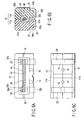
- FIGS. 5A to 5C show the entire structure of the surface-mount current fuse according to the third embodiment of the present invention.
- FIG. 5A is a partially broken front view thereof
- FIG. 5B is a sectional view of FIG. 5A
- FIG. 5C is a bottom view thereof.
- the second linear portions 33a of the pair of metal terminals 30 are bent at each terminal end of the first linear portion 32a and extended in the same directions, which is different from the second embodiment shown in FIG. 4 .
- the second linear portions 33a of the pair of metal terminals 30 are bent toward the insulation case member 11b on one side as seen from the bottom side of the surface-mount current fuse.
- each of the pair of metal terminals 30 has one second linear portion 33a. Because this second linear portion 33a penetrates each of the pair of terminal insertion holes 12, 13 provided in the bottom portion of the case, the shape of the recesses 12a, 13a (or 12b, 13b) for the terminal insertion hole shown in FIG. 2 which constitute the terminal insertion holes 12, 13 is smaller than in FIG. 1 .
- this embodiment may be modified to be provided with the third linear portion 34a like the first embodiment.
- This third linear portion 34a can be used as a test terminal for confirming conduction of the fuse wire 42 after this current fuse is joined to a printed circuit board.
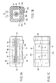
- FIGS. 6A to 6C show the entire configuration of a surface-mount current fuse according to the fourth embodiment of the present invention.
- FIG. 6A is a partially broken front view thereof
- FIG. 6B is a sectional view of FIG. 6A
- FIG. 6C is a bottom view thereof.
- the pair of wall portions 17a, 18a (17b, 18b) is omitted from the first embodiment shown in FIG. 1 .
- a pair of wall portions 22a, 23a (22b, 23b) formed integrally with the insulation case members are provided to hold each apex portion 31 of the pair of metal terminals 30.
- the pair of wall portions 22a, 23a (22b, 23b) are bored into a substantially semicircular shape which agrees with the external shape of the apex portion 31 at a portion which makes contact with the apex portion 31.
- This pair of wall portions 22a, 23a (22b, 23b) take a role as a guide for preventing the fuse element assembly 40 from being bent at the time of assembly and a role of improving the reliability by preventing vibration or shock from being applied to the fuse element assembly 40 after this current fuse is manufactured. Further, the pair of wall portions 22a, 23a (22b, 23b) take a role of blocking scattering of arc gas produced at the time of shutdown like the pair of wall portions 17a, 18a (17b, 18b) shown in FIG. 1 .
- the pair of wall portions 22a, 23a (22b, 23b) for use in the surface-mount current fuse of this embodiment may be used in the surface-mount current fuse of the second and third embodiments.
- the present invention has been described with reference to the embodiments, the present invention is not restricted to the above-described embodiments but may be modified in various ways within a scope not departing from the gist of the invention. Further, the above embodiments contain various stages of the present invention and other embodiment of the present invention can be extracted by an appropriate combination of the disclosed plural components. Even if some components are deleted from all the components indicated in the above embodiments, as long as at least one of the problems which the present invention intends to solve is solved and at least one of the effects which are mentioned as the effects of the present invention is obtained, the configuration excluding the deleted components may be picked up as another embodiment of the present invention.
Landscapes
- Fuses (AREA)
Abstract


Description
- The present invention relates to a surface-mount current fuse mounted on, for example, a printed circuit board.
- With miniaturization and intensification of mounting density of electronic devices accelerated, the miniaturization and intensification of the mounting density have been demanded for a surface-mount current fuse to be mounted on a printed circuit board. As this kind of a conventional surface-mount current fuse, for example, a type disclosed in Jpn. Pat. Appln. KOKAI Publication No.
9-63455 - In the fuse having such a structure, adhesive agent is used for fixing of the lid portion considering a gas pressure when it is broken out, treatment of exhaust gas, fixing of the terminal and the like. Therefore, this kind of fuse has disadvantages in terms of manufacturing with automatic equipment and manufacturing cost. Further, because the fuse wire is stretched in the floating condition in the interior space of the main body, it is likely to be affected by vibration and shock thereby leading to reduction in reliability.
- The present invention has been achieved in views of the above-described circumstances and an object of the invention is to provide a surface-mount current fuse which can be manufactured with automatic equipment, allows its manufacturing cost to be reduced and is hardly affected by vibration and shock, thereby securing high reliability.
- According to one aspect of the present invention, there is provided a surface-mount current fuse comprising: a case which is constructed by melting and joining together end faces of a pair of insulation case members each having a substantially rectangular parallelepiped box shape and is provided with a pair of terminal insertion holes at the bottom portion thereof; a pair of metal terminals each having a loop-like apex portion, a first linear portion extending from the apex portion and a second linear portion which is bent substantially at right angles at a terminal end of the first linear portion; and a fuse element assembly in which fuse wire is wound around bundled rod-like glass fiber materials spirally at a predetermined pitch, wherein the apex portions of the pair of metal terminals are located inside the case, both end portions of the fuse element assembly are inserted and held in the apex portions of the pair of metal terminals while the fuse wire is joined electrically to the pair of metal terminals at each apex portion, the first linear portion of the pair of metal terminals penetrates the pair of terminal insertion holes provided in the bottom portion of the case so that the pair of second linear portions are exposed out of the case, and the second linear portions are located along the bottom portion of the case thereby constituting an electrode terminal.
- The invention can be more fully understood from the following detailed description when taken in conjunction with the accompanying drawings, in which:
-
FIGS. 1A to 1C are a front view, sectional view and bottom view showing the entire configuration of a surface-mount current fuse according to a first embodiment of the present invention; -
FIG. 2 is a perspective view showing the structure of one of a pair of insulation case members shown inFIG. 1 ; -
FIG. 3 is a perspective view for explaining a method for assembling a fuse element assembly; -
FIGS. 4A to 4C are a front view, sectional view and bottom view showing the entire configuration of a surface-mount current fuse according to a second embodiment of the present invention; -
FIGS. 5A to 5C are a front view, sectional view and bottom view showing the entire configuration of a surface-mount current fuse according to a third embodiment of the present invention; and -
FIGS. 6A to 6C are a front view, sectional view and bottom view showing the entire configuration of a surface-mount current fuse according to a fourth embodiment of the present invention. - Hereinafter, embodiments of the present invention will be described with reference to the accompanying drawing.
-
FIGS. 1A to 1C show the entire structure of a surface-mount current fuse according to the first embodiment of the present invention.FIG. 1A is a partially broken front view thereof,FIG. 1B is a sectional view ofFIG. 1A, and FIG. 1C is a bottom view thereof. The surface-mount current fuse of this embodiment includes acase 10, a pair ofmetal terminals 30 and afuse element assembly 40. - The
case 10 is configured by melting and joining open end faces of a pair of moldedinsulation case members -
FIG. 2 is a perspective view showing one of the pair ofinsulation cases Recesses terminal insertion holes insulation case members insulation case members terminal insertion holes case 10, as shown inFIG. 1C . Further,recesses exhaust holes insulation case members insulation case members exhaust holes terminal insertion holes case 10, as shown inFIG. 1C . - Pair of
wall portions insulation case members fuse element assembly 40 as shown inFIG. 2 . Further,recesses exhaust holes exhaust holes case 10 when the pair ofinsulation case members recesses recesses FIG. 1A , the side faces of thecase 10 in which theexhaust holes fuse element assembly 40. - The pair of
metal terminals 30 is formed by bending a metal sheet or a round linear material (metal sheet in this example). As shown inFIG. 1B , the pair ofmetal terminals 30 are constituted of loop-like apex portions 31, a pair of firstlinear portions apex portion 31, a pair of secondlinear portions linear portions linear portions apex portion 31 after being bent substantially at right angles at each terminal end of the pair of secondlinear portions metal terminals 30 has a substantially Ω shape. - As shown in
FIG. 1A , thefuse element assembly 40 is configured by winding afuse wire 42 spirally around a rod-likeglass fiber bundle 41 at a predetermined pitch. In thefuse element assembly 40, thefuse wire 42 is heated by Joule heat produced when a current larger than a rated one (abnormal current produced by an eddy current or a circuit problem) flows so that it is melted in a predetermined time. Thus, thefuse wire 42 is different in diameter and material depending on the rated current, and designed and set to satisfy each characteristic. - The
fuse element assembly 40 is constructed so that both end portions thereof are inserted and held in the interior of eachapex portion 31 of the pair ofmetal terminals 30, and thefuse wire 42 is connected electrically to the pair ofmetal terminals 30 at eachapex portion 31 by spot welding, soldering or the like. - The pair of first
linear portions metal terminals 30 are inserted through each of the pair ofterminal insertion holes case 10 so that theapex portions 31 of the pair ofmetal terminals 30 are located within the interior of thecase 10 when thefuse element assembly 40 is assembled. - As shown in
FIG. 1B , the pairs of the secondlinear portions linear portions metal terminals 30 are exposed out of the case. The secondlinear portions case 10 thereby constituting an electrode terminal for use at the time of joining to a printed circuit board by soldering. The thirdlinear portions linear portions FIG. 1 , recessportions 21 are formed in the pair ofinsulation case members linear portions fuse wire 42 after being joined to a printed circuit board. - The pair of
wall portions insulation case members fuse element assembly 40. The pair ofwall portions assembly 40 at a portion which makes contact with thefuse element assembly 40, thereby taking a role as a guide for preventing thefuse element assembly 40 from being bent at the time of manufacture and preventing vibration or shock from being applied to thefuse element assembly 40 after manufacture so as to improve the reliability of the product. Further, the pair ofwall portions fuse element assembly 40 reaches a highest point with a rapid temperature rise of thefuse element assembly 40. Arc gas produced at this time contains metallic vapor, thereby deterioration of insulation being likely produced after the shutdown. This is an important technical problem which should be solved in a small-size, small-volume product like the surface-mount current fuse of the present invention. In the pair ofwall portions - Pair of small exhaust holes 14, 15 is formed in the bottom portion of the
case 10. The exhaust holes 14, 15 have an effect of reducing the pressure of the arc gas at the time of the shutdown. Further, the pair of small exhaust holes 19, 20 are formed in the side faces of thecase 10. The exhaust holes 19, 20 also have the effect of reducing the pressure of the arc gas at the time of the shutdown. - The surface-mount current fuse of this embodiment is manufactured as follows. That is, as shown in
FIG. 3 , the pair ofmetal terminals 30 is formed in a condition in which the loop-like apex portion 31 is open to some extent and both end portions of thefuse element assembly 40 are automatically inserted into theapex portions 31 of the pair ofmetal terminals 30. After that, the firstlinear portions fuse wire 41 is welded or soldered to theapex portion 31 while the shape thereof is fixed. - With the
fuse element assembly 40 assembled, theapex portions 31 of the pair ofmetal terminals 30 are accommodated within theinsulation case member 11a (or 11b) on one side and the pair of firstlinear portions metal terminals 30 is inserted into therecesses insulation case member 11a. After that, the otherinsulation case member 11b (or 11a) is mounted so that thefuse element assembly 40 and the pair ofmetal terminals 30 are positioned. After that, the open end faces of the pair ofinsulation case members case 10. As a result of this joining, the pair ofmetal terminals 30 is sandwiched by thecase 10 so as to stabilize the position thereof. - The surface-mount current fuse of this embodiment can be manufactured with automatic equipment because it has a structure suitable for the manufacturing with the automatic equipment. Further, because it does not need the use of an adhesive agent as is conventional, manufacturing cost thereof can be reduced.
- Although in this embodiment, a case of forming the pair of
metal terminals 30 by bending a metal sheet has been described above, the pair ofmetal terminals 30 may be formed by bending a round wire material. In this case, it is permissible to leave the pair of firstlinear portions like apex portion 31, the pair of secondlinear portions linear portions -
FIGS. 4A to 4C show the entire structure of a surface-mount current fuse according to the second embodiment of the present invention.FIG. 4A is a partially broken perspective view thereof,FIG. 4B is a sectional view thereof andFIG. 4C is a bottom view thereof. - The surface-mount current fuse of this embodiment is different from the first embodiment shown in
FIG. 1 in the shape of the pair ofmetal terminals 30. That is, each of the pair ofmetal terminals 30 is formed by bending a metal sheet or a rounded wire material (metal sheet in this example). As shown inFIG. 4B , the metal terminal is composed of a loop-like apex portion 31, a firstlinear portion 32a extending from thisapex portion 31 and a secondlinear portion 33a bent substantially at right angles at a terminal end of the firstlinear portion 32a. - Also in this case, the
fuse element assembly 40 is configured so that both end portions thereof are inserted and held in the interior of theapex portions 31 of the pair ofmetal terminals 30 and thefuse wire 42 is joined electrically to theapex portions 31 of the pair ofmetal terminals 30 by spot welding, soldering or the like. - Each first
linear portion 32a of the pair ofmetal terminals 30 is inserted through each of the pair of terminal insertion holes 12, 13 in the bottom portion of thecase 10, so that theapex portions 31 of the pair ofmetal terminals 30 are located within the interior of thecase 10 when thefuse element assembly 40 is assembled. - As shown in
FIG. 4B , the secondlinear portion 33a of the pair ofmetal terminals 30 is exposed out of the case and the secondlinear portion 33a is located along the bottom portion of thecase 10, thereby constructing an electrode terminal for use in joining of this current fuse to a printed circuit board by soldering. In this case, the secondlinear portions 33a of the pair ofmetal terminals 30 are bent at a terminal end of the firstlinear portion 32a and extended in opposite directions to each other. That is, as shown inFIG. 4C , the secondlinear portions 33a of the pair ofmetal terminals 30 are located on a diagonal line as seen from the bottom side of the surface-mount current fuse. - In this embodiment, each of the pair of
metal terminals 30 has one secondlinear portion 33a. Because this secondlinear portion 33a penetrates each of the pair of terminal insertion holes 12, 13 provided in the bottom portion of the case, the shape of therecesses FIG. 2 which constitute the terminal insertion holes 12, 13 is smaller than inFIG. 1 . - Although in this embodiment, a case where the pair of
metal terminals 30 are provided with no thirdlinear portion 34a has been described, this embodiment may be modified by providing the thirdlinear portion 34a like the first embodiment. This thirdlinear portion 34a can be used as a test terminal for confirming conduction of thefuse wire 42 after this is joined to the printed circuit board. -
FIGS. 5A to 5C show the entire structure of the surface-mount current fuse according to the third embodiment of the present invention.FIG. 5A is a partially broken front view thereof,FIG. 5B is a sectional view ofFIG. 5A and FIG. 5C is a bottom view thereof. - In the surface-mount current fuse of this embodiment, the second
linear portions 33a of the pair ofmetal terminals 30 are bent at each terminal end of the firstlinear portion 32a and extended in the same directions, which is different from the second embodiment shown inFIG. 4 . For example, as shown inFIG. 5C , the secondlinear portions 33a of the pair ofmetal terminals 30 are bent toward theinsulation case member 11b on one side as seen from the bottom side of the surface-mount current fuse. - According to this embodiment, as in the second embodiment, each of the pair of
metal terminals 30 has one secondlinear portion 33a. Because this secondlinear portion 33a penetrates each of the pair of terminal insertion holes 12, 13 provided in the bottom portion of the case, the shape of therecesses FIG. 2 which constitute the terminal insertion holes 12, 13 is smaller than inFIG. 1 . - Although in this embodiment, a case where the pair of
metal terminals 30 are provided with no thirdlinear portion 34a has been described, this embodiment may be modified to be provided with the thirdlinear portion 34a like the first embodiment. This thirdlinear portion 34a can be used as a test terminal for confirming conduction of thefuse wire 42 after this current fuse is joined to a printed circuit board. -
FIGS. 6A to 6C show the entire configuration of a surface-mount current fuse according to the fourth embodiment of the present invention.FIG. 6A is a partially broken front view thereof,FIG. 6B is a sectional view ofFIG. 6A, and FIG. 6C is a bottom view thereof. - In the surface-mount current fuse of this embodiment, the pair of
wall portions FIG. 1 . Instead, a pair ofwall portions apex portion 31 of the pair ofmetal terminals 30. The pair ofwall portions apex portion 31 at a portion which makes contact with theapex portion 31. This pair ofwall portions fuse element assembly 40 from being bent at the time of assembly and a role of improving the reliability by preventing vibration or shock from being applied to thefuse element assembly 40 after this current fuse is manufactured. Further, the pair ofwall portions wall portions FIG. 1 . - The pair of
wall portions - Although the present invention has been described with reference to the embodiments, the present invention is not restricted to the above-described embodiments but may be modified in various ways within a scope not departing from the gist of the invention. Further, the above embodiments contain various stages of the present invention and other embodiment of the present invention can be extracted by an appropriate combination of the disclosed plural components. Even if some components are deleted from all the components indicated in the above embodiments, as long as at least one of the problems which the present invention intends to solve is solved and at least one of the effects which are mentioned as the effects of the present invention is obtained, the configuration excluding the deleted components may be picked up as another embodiment of the present invention.
Claims (7)
- A surface-mount current fuse characterized by comprising:a case (10) which is constructed by melting and joining together end faces of a pair of insulation case members (11a, 11b) each having a substantially rectangular parallelepiped box shape and is provided with a pair of terminal insertion holes (12, 13) at the bottom portion thereof;a pair of metal terminals (30) each having a loop-like apex portion (31), a first linear portion (32a) extending from the apex portion and a second linear portion (33a) which is bent substantially at right angles at a terminal end of the first linear portion; anda fuse element assembly (40) in which fuse wire (42) is wound around bundled rod-like glass fiber materials (41) spirally at a predetermined pitch,wherein the apex portions (31) of the pair of metal terminals (30) are located inside the case (10),both end portions of the fuse element assembly (40) are inserted and held in the apex portions (31) of the pair of metal terminals (30) while the fuse wire (42) is joined electrically to the pair of metal terminals (30) at each apex portion (31),the first linear portion (32a) of the pair of metal terminals (30) penetrates the pair of terminal insertion holes (12, 13) provided in the bottom portion of the case (10) so that the pair of second linear portions (33a) are exposed out of the case (10), andthe second linear portions (33a) are located along the bottom portion of the case (10) thereby constituting an electrode terminal.
- The surface-mount current fuse according to claim 1, characterized in that each of the pair of metal terminals (30) has a third linear portion (32b) extending in the same direction as the extending direction of the first linear portion (32a) from the loop-like apex portion (31) and a fourth linear portion (33b) which is bent in an opposite direction to the second linear portion (33a) at a terminal end of the third linear portion.
- The surface-mount current fuse according to claim 1, characterized in that the pair of insulation case members (11a, 11b) have a pair of wall portions (17a, 18a, 17b, 18b) which hold the fuse element assembly (40) and are molded integrally with the insulation case member at positions opposed to each other inside the case (10).
- The surface-mount current fuse according to claim 1, characterized in that exhaust holes (14, 15, 19, 20) for reducing a gas pressure when the fuse wire (42) is shut down are provided in the bottom portion and the side faces of the case (10).
- The surface-mount current fuse according to claim 1, characterized in that the pair of insulation case members (11a, 11b) have a pair of wall portions (22a, 23a, 22b, 23b) which are molded integrally with the insulation case member and hold the apex portion (31) of the pair of metal terminals (30) at positions opposed to each other inside the case (10).
- The surface-mount current fuse according to claim 1, characterized in that the second linear portions (33a) of the pair of metal terminals (30) are bent substantially at right angles at the terminal end of the first linear portion (32a) and extend in opposite directions to each other.
- The surface-mount current fuse according to claim 1, characterized in that the second linear portions (33a) of the pair of metal terminals (30) are bent substantially at right angles at the terminal end of the first linear portion (32a) and extend in the same direction.
Applications Claiming Priority (1)
| Application Number | Priority Date | Filing Date | Title |
|---|---|---|---|
| JP2007244431A JP4348385B2 (en) | 2007-09-20 | 2007-09-20 | Surface-mount current fuse |
Publications (3)
| Publication Number | Publication Date |
|---|---|
| EP2040281A2 true EP2040281A2 (en) | 2009-03-25 |
| EP2040281A3 EP2040281A3 (en) | 2012-12-19 |
| EP2040281B1 EP2040281B1 (en) | 2014-06-04 |
Family
ID=40225583
Family Applications (1)
| Application Number | Title | Priority Date | Filing Date |
|---|---|---|---|
| EP08164573.1A Not-in-force EP2040281B1 (en) | 2007-09-20 | 2008-09-18 | Surface-mount current fuse |
Country Status (3)
| Country | Link |
|---|---|
| EP (1) | EP2040281B1 (en) |
| JP (1) | JP4348385B2 (en) |
| KR (1) | KR101017119B1 (en) |
Cited By (3)
| Publication number | Priority date | Publication date | Assignee | Title |
|---|---|---|---|---|
| CN102496536A (en) * | 2011-12-27 | 2012-06-13 | 东莞市贝特电子科技有限公司 | Explosion-proof fuse and method for manufacturing same |
| CN105518820A (en) * | 2013-08-28 | 2016-04-20 | 迪睿合株式会社 | Fuse element and fuse unit |
| DE102017214682A1 (en) * | 2017-08-22 | 2019-02-28 | Leoni Bordnetz-Systeme Gmbh | Electrical fuse element and circuit board with electrical fuse element soldered thereto |
Families Citing this family (7)
| Publication number | Priority date | Publication date | Assignee | Title |
|---|---|---|---|---|
| US10325746B2 (en) * | 2016-11-15 | 2019-06-18 | Littelfuse, Inc. | Ventilated fuse housing |
| JP2020507884A (en) * | 2017-11-27 | 2020-03-12 | 功得電子工業股▲分▼有限公司Conquer Electoronics Co.,Ltd. | Fuse wire fixing structure in fuse |
| TWI743008B (en) * | 2021-03-11 | 2021-10-11 | 功得電子工業股份有限公司 | Surface mount fuse |
| CN115083858A (en) * | 2021-03-15 | 2022-09-20 | 功得电子工业股份有限公司 | Paster fuse |
| TWI827292B (en) * | 2022-09-30 | 2023-12-21 | 功得電子工業股份有限公司 | Lightweight industrial fuse |
| JP2025181425A (en) * | 2024-05-31 | 2025-12-11 | デクセリアルズ株式会社 | Protection Elements |
| JP2025181415A (en) * | 2024-05-31 | 2025-12-11 | デクセリアルズ株式会社 | Protection elements and modules |
Citations (1)
| Publication number | Priority date | Publication date | Assignee | Title |
|---|---|---|---|---|
| JPH0963455A (en) | 1995-08-30 | 1997-03-07 | S O C Kk | Surface mount micro electric current fuse |
Family Cites Families (6)
| Publication number | Priority date | Publication date | Assignee | Title |
|---|---|---|---|---|
| DE2949432C2 (en) * | 1979-12-08 | 1986-08-07 | Georg Rudolf 8411 Zeitlarn Sillner | Plug-in fuse |
| US4751489A (en) | 1986-08-18 | 1988-06-14 | Cooper Industries, Inc. | Subminiature fuses |
| JP3820143B2 (en) * | 2001-02-16 | 2006-09-13 | エス・オー・シー株式会社 | Surface mount type small fuse |
| WO2002071432A1 (en) * | 2001-03-02 | 2002-09-12 | Wickmann-Werke Gmbh | Fuse component |
| JP2004253218A (en) * | 2003-02-19 | 2004-09-09 | Nippon Seisen Kk | Small fuse |
| KR100689021B1 (en) | 2004-12-17 | 2007-03-12 | 스마트전자 주식회사 | Surface-Mount Small Fuse and Manufacturing Method Thereof |
-
2007
- 2007-09-20 JP JP2007244431A patent/JP4348385B2/en not_active Expired - Fee Related
-
2008
- 2008-09-18 EP EP08164573.1A patent/EP2040281B1/en not_active Not-in-force
- 2008-09-19 KR KR1020080092012A patent/KR101017119B1/en not_active Expired - Fee Related
Patent Citations (1)
| Publication number | Priority date | Publication date | Assignee | Title |
|---|---|---|---|---|
| JPH0963455A (en) | 1995-08-30 | 1997-03-07 | S O C Kk | Surface mount micro electric current fuse |
Cited By (6)
| Publication number | Priority date | Publication date | Assignee | Title |
|---|---|---|---|---|
| CN102496536A (en) * | 2011-12-27 | 2012-06-13 | 东莞市贝特电子科技有限公司 | Explosion-proof fuse and method for manufacturing same |
| CN105518820A (en) * | 2013-08-28 | 2016-04-20 | 迪睿合株式会社 | Fuse element and fuse unit |
| TWI631590B (en) * | 2013-08-28 | 2018-08-01 | 迪睿合股份有限公司 | Fuse unit, fuse element |
| DE102017214682A1 (en) * | 2017-08-22 | 2019-02-28 | Leoni Bordnetz-Systeme Gmbh | Electrical fuse element and circuit board with electrical fuse element soldered thereto |
| DE102017214682B4 (en) | 2017-08-22 | 2019-03-07 | Leoni Bordnetz-Systeme Gmbh | Electrical fuse element and circuit board with electrical fuse element soldered thereto |
| US10553383B2 (en) | 2017-08-22 | 2020-02-04 | Leoni Bordnetz-Systeme Gmbh | Electrical fuse element |
Also Published As
| Publication number | Publication date |
|---|---|
| EP2040281A3 (en) | 2012-12-19 |
| KR20090031280A (en) | 2009-03-25 |
| EP2040281B1 (en) | 2014-06-04 |
| KR101017119B1 (en) | 2011-02-25 |
| JP2009076330A (en) | 2009-04-09 |
| JP4348385B2 (en) | 2009-10-21 |
Similar Documents
| Publication | Publication Date | Title |
|---|---|---|
| EP2040281B1 (en) | Surface-mount current fuse | |
| JP3820143B2 (en) | Surface mount type small fuse | |
| JP4844848B2 (en) | Connection structure of electronic components | |
| JP3862870B2 (en) | Electrical components with solderless terminal fittings | |
| JP2012522334A (en) | Solderless surface mount fuse | |
| KR20060048797A (en) | Cotton Mount Coil Parts | |
| US6778061B2 (en) | Fuse | |
| JPWO2019004038A1 (en) | Inductor component and manufacturing method thereof | |
| WO2017047738A1 (en) | Terminal-equipped electrical wire and wiring module | |
| US5807121A (en) | Junction component for connecting the electrical leads of a printed circuit board and a separate electrical unit | |
| EP2147480A1 (en) | Electrical male terminal | |
| KR101447490B1 (en) | The high capacitance fuse | |
| US8325464B2 (en) | Coin type electric double-layered capacitor, and capacitor-packaged element | |
| JP2886005B2 (en) | LC filter | |
| TW202133207A (en) | Current-limiting fuse | |
| US20240412936A1 (en) | Electrical fuse | |
| JP3619812B2 (en) | Low profile transformer | |
| JP5219987B2 (en) | Board mounted terminal block and printed wiring board assembly | |
| KR100929822B1 (en) | Surface-Mount Small Fuses | |
| JP7245062B2 (en) | COIL COMPONENT, ELECTRONIC DEVICE, AND COIL COMPONENT MANUFACTURING METHOD | |
| EP4425526A1 (en) | High breaking capacity fuses with metal reinforcements | |
| KR102667271B1 (en) | Band type connector | |
| JP3644071B2 (en) | Electromagnetic equipment | |
| CN215527943U (en) | Conductive terminal, electric connector and temperature sensor | |
| TWI389361B (en) | Piezoelectric transformer device |
Legal Events
| Date | Code | Title | Description |
|---|---|---|---|
| PUAI | Public reference made under article 153(3) epc to a published international application that has entered the european phase |
Free format text: ORIGINAL CODE: 0009012 |
|
| 17P | Request for examination filed |
Effective date: 20080918 |
|
| AK | Designated contracting states |
Kind code of ref document: A2 Designated state(s): AT BE BG CH CY CZ DE DK EE ES FI FR GB GR HR HU IE IS IT LI LT LU LV MC MT NL NO PL PT RO SE SI SK TR |
|
| AX | Request for extension of the european patent |
Extension state: AL BA MK RS |
|
| PUAL | Search report despatched |
Free format text: ORIGINAL CODE: 0009013 |
|
| AK | Designated contracting states |
Kind code of ref document: A3 Designated state(s): AT BE BG CH CY CZ DE DK EE ES FI FR GB GR HR HU IE IS IT LI LT LU LV MC MT NL NO PL PT RO SE SI SK TR |
|
| AX | Request for extension of the european patent |
Extension state: AL BA MK RS |
|
| RIC1 | Information provided on ipc code assigned before grant |
Ipc: H01H 85/041 20060101AFI20121112BHEP |
|
| AKX | Designation fees paid |
Designated state(s): CH DE GB LI SE |
|
| GRAP | Despatch of communication of intention to grant a patent |
Free format text: ORIGINAL CODE: EPIDOSNIGR1 |
|
| INTG | Intention to grant announced |
Effective date: 20140108 |
|
| GRAS | Grant fee paid |
Free format text: ORIGINAL CODE: EPIDOSNIGR3 |
|
| GRAA | (expected) grant |
Free format text: ORIGINAL CODE: 0009210 |
|
| AK | Designated contracting states |
Kind code of ref document: B1 Designated state(s): CH DE GB LI SE |
|
| REG | Reference to a national code |
Ref country code: GB Ref legal event code: FG4D |
|
| REG | Reference to a national code |
Ref country code: CH Ref legal event code: EP Ref country code: CH Ref legal event code: NV Representative=s name: E. BLUM AND CO. AG PATENT- UND MARKENANWAELTE , CH |
|
| REG | Reference to a national code |
Ref country code: DE Ref legal event code: R096 Ref document number: 602008032541 Country of ref document: DE Effective date: 20140717 |
|
| REG | Reference to a national code |
Ref country code: SE Ref legal event code: TRGR |
|
| REG | Reference to a national code |
Ref country code: DE Ref legal event code: R097 Ref document number: 602008032541 Country of ref document: DE |
|
| PLBE | No opposition filed within time limit |
Free format text: ORIGINAL CODE: 0009261 |
|
| STAA | Information on the status of an ep patent application or granted ep patent |
Free format text: STATUS: NO OPPOSITION FILED WITHIN TIME LIMIT |
|
| 26N | No opposition filed |
Effective date: 20150305 |
|
| REG | Reference to a national code |
Ref country code: DE Ref legal event code: R097 Ref document number: 602008032541 Country of ref document: DE Effective date: 20150305 |
|
| PGFP | Annual fee paid to national office [announced via postgrant information from national office to epo] |
Ref country code: DE Payment date: 20170923 Year of fee payment: 10 Ref country code: GB Payment date: 20170714 Year of fee payment: 10 Ref country code: CH Payment date: 20170802 Year of fee payment: 10 |
|
| PGFP | Annual fee paid to national office [announced via postgrant information from national office to epo] |
Ref country code: SE Payment date: 20170816 Year of fee payment: 10 |
|
| REG | Reference to a national code |
Ref country code: DE Ref legal event code: R119 Ref document number: 602008032541 Country of ref document: DE |
|
| REG | Reference to a national code |
Ref country code: SE Ref legal event code: EUG Ref country code: CH Ref legal event code: PL |
|
| GBPC | Gb: european patent ceased through non-payment of renewal fee |
Effective date: 20180918 |
|
| PG25 | Lapsed in a contracting state [announced via postgrant information from national office to epo] |
Ref country code: SE Free format text: LAPSE BECAUSE OF NON-PAYMENT OF DUE FEES Effective date: 20180919 |
|
| PG25 | Lapsed in a contracting state [announced via postgrant information from national office to epo] |
Ref country code: DE Free format text: LAPSE BECAUSE OF NON-PAYMENT OF DUE FEES Effective date: 20190402 |
|
| PG25 | Lapsed in a contracting state [announced via postgrant information from national office to epo] |
Ref country code: CH Free format text: LAPSE BECAUSE OF NON-PAYMENT OF DUE FEES Effective date: 20180930 Ref country code: LI Free format text: LAPSE BECAUSE OF NON-PAYMENT OF DUE FEES Effective date: 20180930 |
|
| PG25 | Lapsed in a contracting state [announced via postgrant information from national office to epo] |
Ref country code: GB Free format text: LAPSE BECAUSE OF NON-PAYMENT OF DUE FEES Effective date: 20180918 |