EP2040279A1 - Module électronique pour bobine CA/CC dans un contacteur électromagnétique - Google Patents
Module électronique pour bobine CA/CC dans un contacteur électromagnétique Download PDFInfo
- Publication number
- EP2040279A1 EP2040279A1 EP08164375A EP08164375A EP2040279A1 EP 2040279 A1 EP2040279 A1 EP 2040279A1 EP 08164375 A EP08164375 A EP 08164375A EP 08164375 A EP08164375 A EP 08164375A EP 2040279 A1 EP2040279 A1 EP 2040279A1
- Authority
- EP
- European Patent Office
- Prior art keywords
- voltage
- coil
- pulse
- predetermined
- response
- Prior art date
- Legal status (The legal status is an assumption and is not a legal conclusion. Google has not performed a legal analysis and makes no representation as to the accuracy of the status listed.)
- Withdrawn
Links
Images


Classifications
-
- H—ELECTRICITY
- H01—ELECTRIC ELEMENTS
- H01H—ELECTRIC SWITCHES; RELAYS; SELECTORS; EMERGENCY PROTECTIVE DEVICES
- H01H47/00—Circuit arrangements not adapted to a particular application of the relay and designed to obtain desired operating characteristics or to provide energising current
- H01H47/22—Circuit arrangements not adapted to a particular application of the relay and designed to obtain desired operating characteristics or to provide energising current for supplying energising current for relay coil
- H01H47/32—Energising current supplied by semiconductor device
- H01H47/325—Energising current supplied by semiconductor device by switching regulator
-
- H—ELECTRICITY
- H01—ELECTRIC ELEMENTS
- H01H—ELECTRIC SWITCHES; RELAYS; SELECTORS; EMERGENCY PROTECTIVE DEVICES
- H01H47/00—Circuit arrangements not adapted to a particular application of the relay and designed to obtain desired operating characteristics or to provide energising current
-
- H—ELECTRICITY
- H01—ELECTRIC ELEMENTS
- H01H—ELECTRIC SWITCHES; RELAYS; SELECTORS; EMERGENCY PROTECTIVE DEVICES
- H01H47/00—Circuit arrangements not adapted to a particular application of the relay and designed to obtain desired operating characteristics or to provide energising current
- H01H47/22—Circuit arrangements not adapted to a particular application of the relay and designed to obtain desired operating characteristics or to provide energising current for supplying energising current for relay coil
- H01H47/223—Circuit arrangements not adapted to a particular application of the relay and designed to obtain desired operating characteristics or to provide energising current for supplying energising current for relay coil adapted to be supplied by AC
Definitions
- This invention relates to electromagnetic contactors and particularly to the implementation of electromagnetic contactors comprising AC/DC coils.
- Contactors are utilized as electrically controlled devices for power circuits.
- contactors are assembled from three primary elements: a contact structure for carrying current, an electromagnetic assembly for providing the force to close the contacts of the contact structure, and a frame housing for enclosing the contact and electromagnetic assembly.
- a contact structure for carrying current
- an electromagnetic assembly for providing the force to close the contacts of the contact structure
- a frame housing for enclosing the contact and electromagnetic assembly.
- the power supply is a DC supply
- the only resistance that is available to limit the DC supply is that of the control coil itself, therefore necessitating the implementation of DC control coils that are much larger in size than AC control coils for contactors that are specified for use within DC coil supply systems.
- the disparity in coils sizes leads to increased manufacturing costs since two contactor devices comprising differing control coils must be constructed for devices constructed for similar voltage ratings.
- the electromagnet designs for AC & DC contactors are also different.
- An exemplary embodiment of the present invention comprises an electromagnetic contactor device.
- the electromagnetic contactor device comprises a control module.
- the control module comprises a power circuit, wherein the power circuit comprises a coil assembly, further, the power circuit is configured to receive an AC or DC supply voltage.
- the control module also comprises an analog control circuit, the analog control circuit being in communication with the power circuit, wherein the control circuit is configured to monitor a coil voltage within the coil assembly.
- a further exemplary embodiment of the present invention comprises a method for utilizing a control module as an interfaced control of an AC/DC control coil.
- the method comprises monitoring a coil voltage of the control coil, determining if the coil voltage is greater than a predetermined dropout voltage, and determining if the coil voltage is greater than a predetermined pickup voltage.
- the method also comprises resetting an astable pulse in the event that the coil voltage is determined to be less than the predetermined dropout voltage.
- Exemplary embodiments of the present invention comprise a magnet coil assembly that forms an important aspect of the control circuit of the present invention.
- the present invention implements a novel AC/DC coil by the operations that are initiated within an electronic control module that is interfaced with a supply voltage and the control coil.
- the control module allows for a sufficient monostable time period of switching that allows for the movable contacts of a contactor to pickup or make contact with the non-movable contacts of the contactor. This period is followed by an astable period that assures that a hold-on condition will be sustained within the contactor.
- the pulse generator utilized within exemplary embodiments of the present invention is configured to output astable and monostable pulses.
- astable pulse generation refers to an oscillating pulse that has no permanent state since it continuously changes its state, producing a square wave output of a predetermined timing cycle.
- a monostable pulse generation outputs a single output pulse-HIGH or LOW- when a suitable pulse trigger signal is applied. This trigger signal initiates a timing cycle which causes the output of the monostable to change state at the start of the timing cycle and remain in this secondary state until it resets itself back to its original state at the end of the timing cycle.
- the duty-cycle of an astable period is increased in the event of a decreasing coil supply voltage, thus ensuring an optimum contact holding force.
- the present invention does not require the use of a micro-controller or a driver-circuit to accomplish the operational goals of the present invention. Additionally, all circuits that are implemented within the exemplary embodiments of the present invention are purely analog based.
- the present invention implements an AC/DC coil within exemplary embodiments.
- DC supply coils are much larger in scale than their AC equivalents.
- the present invention does not require the separate design of an AC or DC coil within exemplary embodiments.
- the AC and DC supply coils are featured within the same coil, thereby substantially reducing the size of DC coils that can be implemented within a contactor device.
- same electromagnet system whether AC or DC based, is suitable to enable the operational functions of the DC contactor of the exemplary embodiments of the present invention.
- This inventive aspect is accomplished by cutting or lowering the dc supply voltage during a hold-on condition within the contactor, thus eliminating the need to have a larger DC supply coil.
- a further advantage of the present invention is that by instituting a variable duty cycle in the astable mode of operation, the duty cycle increases as the voltage decreases, thus avoiding nuisance tripping events.
- Fig. 1 shows a cross-sectional diagram of a contactor device 100.
- the contactor 100 comprises a movable magnetic control coil magnet contact assembly 6, a coil assembly 3, a fixed magnet with base plate assembly 5, and fixed contact plates 7.
- the electronic control module 1 is interfaced between the control coil power supply terminals 4 and the control coil assembly 3.
- the elements of the contactor are enclosed within a housing 8.
- the electronic control module 1 is physically configured as a functional intermediary between the contactor 100 and the power supply for the contactor 100. This aspect is essential for allowing the exemplary embodiments of the present invention to provide the use of the same control coil assembly 3 for both AC and DC power supplies.
- the electronic control module 1 comprises a power supply circuit comprising a buck converter circuit; and a control circuit. Each of the fore-mentioned operational components further comprises a series of functional sub-components.
- the power supply circuit acts as the constant output voltage source for the various ranges of input voltage-though the output voltage of the power supply circuit remains fixed at 9V.
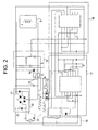
- Fig. 2 shows a diagram detailing the elements of the electronic control module 1.
- a bridge rectifying circuit 10 is used for rectifying a supply voltage to the coil assembly 3, wherein the supply voltage can be either an AC or DC supply voltage.
- Two electrolytic capacitors 13 are implemented to separately filter the voltage for the power supply circuit and the control circuit.
- the power circuit comprises the bridge rectifier 10, the filter 13, the coil assembly 3, a diode 14, and a switching device 11.
- the control circuit comprises a pulse-generator 17, a control logic circuit 18, an OR circuit 12, a voltage dependent resistor circuit 16, and a buck converter (step down DC to DC converter) control voltage regulator circuit 15.
- the rectifier circuit 10 comprises a bridge rectifier 22 and a pair of diodes 21.
- the output from the bridge is fed to the power circuit.
- the pair of diodes 21 feed the control voltage regulator circuit 15.
- the positive terminal of the bridge rectifier 22 is connected to one of the coil terminals 4; the other coil terminal 4 is connected in series with the switching device 11.
- the use of the rectifier circuit 10 can be dispensed with in the instance that it is desired that a DC power supply be utilized.
- the control circuit requires a power supply of 9V, wherein a constant voltage is supplied to the control circuit via the control voltage regulator circuit 15 (e.g., this constant voltage can be supplied using a low drop-out (LDO) voltage regulator in combination with a switching voltage regulator circuit).
- LDO low drop-out
- the input voltages are divide it into three different ranges: a low range of 12V, a mid-range of 24V - 60V; and a high-range of 72V - 440V.
- a low dropout voltage regulator is implemented in the instance of the occurrence of a low coil voltage of 12V.
- a switching circuit is implemented in combination with the LDO voltage regulator.
- An exemplary switching circuit that can be implemented within exemplary embodiments of the present invention is shown in FIG. 3 .
- the switching voltage regulator circuit shown in FIG. 3 comprises a switching IC IR2153 that drives the MOSFET Q1 of the buck converter.
- the input resistance R1 plays a very important role in determining the circuit input voltage range. As such, the input resistance R1 is utilized with the LDO voltage regulator.
- the switching voltage regulator of FIG. 3 is again utilized in the instance of the occurrence of a high-range voltage of 72V - 440V. Further, the value of the input resistance R1 is accordingly adjusted in order to obtain a required voltage range.
- the potential divider can be configured to be manually configured.
- this option can be provided to a user via an accessible DIP selection switch, wherein the selection ranges are 12V, 24V, 48V, 60V, 72V, 110V, 230V, and 440V.
- the control logic circuit 18 monitors the coil assembly 3 supply voltage (step 405 of Fig. 4 ), and in response to its monitoring activities, produces required control outputs. A determination is made at the control logic circuit 18 to ascertain if the supply voltage is greater than a dropout voltage that has been predetermined for the contactor (step 410). When the coil assembly 3 supply voltage is greater than the predetermined dropout voltage of the contactor, the controller 18 sets a RESET input for an astable pulse 23 that is generated at the pulse generator 17 to HIGH. The pulse generator 17 generates the astable pulses 23 with high frequency (e.g., at approximately 500Hz) (step 415). However, the coil assembly current in this instance is not enough for the contact pickup with the contactor 100. Within aspects of the present invention the pickup voltage of the contactor 100 is always greater than the dropout voltage.
- the control logic further determines if the coil voltage is greater than the pickup voltage of the contactor 100 (step 420). In the event that the coil voltage is greater than the pickup voltage of the contactor 100, the controller 18 sets the RESET input of the monostable pulse generator of the pulse generator 17 to HIGH. As the supply voltage crosses the pickup voltage, the pulse generator 17 generates a monostable pulse 24 (step 425). The monostable pulse 24 is output for a time period more than or equal to the predetermined pickup time of the contactor 100.
- the OR circuit 12 adds together the two outputs of the pulse generator 17 (i.e., the astable output & the monostable output). The resultant output comprises the monostable pulse of the designed time period. The generation of this output allows for a proper pickup of the contacts (6, 7) within the contactor 100.
- the duty cycle at the rated voltage is determined based upon the spring force within the contactor 100.
- the duty cycle is designed for the minimum force required for holding the contacts on at a rated voltage, this aspect thus ensuring minimum coil energy consumption.
- the resistance offered by voltage dependent resistor circuit 16 increases.
- the voltage dependent resistor circuit ensures that the pulse width of the astable pulse 23 increases with the decreasing supply voltage. This increases the duty cycle of the astable mode linearly with the decrease in voltage. This operation ensures the nearly constant hold on force within the assembly coil 3.
- the controller 18 resets the astable pulse generator 17 (step 430), and the contacts 6 drop out.
Applications Claiming Priority (1)
| Application Number | Priority Date | Filing Date | Title |
|---|---|---|---|
| US11/859,396 US20090080133A1 (en) | 2007-09-21 | 2007-09-21 | Electronic module for ac/dc coil within an electromagnetic contactor |
Publications (1)
| Publication Number | Publication Date |
|---|---|
| EP2040279A1 true EP2040279A1 (fr) | 2009-03-25 |
Family
ID=40011322
Family Applications (1)
| Application Number | Title | Priority Date | Filing Date |
|---|---|---|---|
| EP08164375A Withdrawn EP2040279A1 (fr) | 2007-09-21 | 2008-09-16 | Module électronique pour bobine CA/CC dans un contacteur électromagnétique |
Country Status (8)
| Country | Link |
|---|---|
| US (1) | US20090080133A1 (fr) |
| EP (1) | EP2040279A1 (fr) |
| JP (1) | JP2009076457A (fr) |
| KR (1) | KR20090031334A (fr) |
| CN (1) | CN101393820A (fr) |
| AU (1) | AU2008207687A1 (fr) |
| CA (1) | CA2639283A1 (fr) |
| MX (1) | MX2008011906A (fr) |
Cited By (3)
| Publication number | Priority date | Publication date | Assignee | Title |
|---|---|---|---|---|
| CN102244374A (zh) * | 2011-07-16 | 2011-11-16 | 合肥天海电气技术有限公司 | 数字可变延时智能防晃电装置 |
| US9287074B2 (en) | 2012-09-13 | 2016-03-15 | Schneider Electric Industries Sas | Relay for automatically selecting a monitoring range |
| US20200411267A1 (en) * | 2018-01-22 | 2020-12-31 | Omron Corporation | Electromagnetic relay and terminal block |
Families Citing this family (9)
| Publication number | Priority date | Publication date | Assignee | Title |
|---|---|---|---|---|
| US9307615B2 (en) | 2014-07-17 | 2016-04-05 | General Electric Company | Field selectable contactor control modules |
| CN104362041B (zh) * | 2014-11-18 | 2016-08-10 | 成都海沃斯电气技术有限公司 | 交流接触器无源控制电路 |
| DE102015117593A1 (de) * | 2015-10-15 | 2017-04-20 | Eaton Electrical Ip Gmbh & Co. Kg | Steuervorrichtung für einen elektromagnetischen Antrieb eines Schaltgeräts |
| EP3319110B1 (fr) | 2016-11-03 | 2019-05-15 | Rockwell Automation Switzerland GmbH | Contacteur électromagnétique |
| JP6260677B1 (ja) | 2016-12-02 | 2018-01-17 | 富士電機機器制御株式会社 | 電磁接触器 |
| CN108630497A (zh) * | 2017-03-23 | 2018-10-09 | 施耐德电器工业公司 | 电子式控制接触器 |
| US11735387B2 (en) * | 2019-10-17 | 2023-08-22 | Mitsubishi Electric Corporation | Electromagnetic contactor |
| US11749476B2 (en) * | 2021-08-05 | 2023-09-05 | Lear Corporation | Electrical unit with turn-off switch and system |
| WO2024073704A1 (fr) * | 2022-09-29 | 2024-04-04 | Ademco Inc. | Système et procédé de régulation d'un signal de tension |
Citations (5)
| Publication number | Priority date | Publication date | Assignee | Title |
|---|---|---|---|---|
| EP0297957A1 (fr) * | 1987-07-03 | 1989-01-04 | Petercem S.A. | Dispositif de commande et de contrôle de contacteur, et procédé de contrôle correspondant |
| US4878147A (en) | 1987-08-05 | 1989-10-31 | Kabushiki Kaisha Toshiba | Electromagnetic coil drive device |
| US5262680A (en) * | 1991-07-08 | 1993-11-16 | Industrial Technology Research Institute | Switch control apparatus for eliminating intermittent on/off condition on a power supply switch |
| US5287243A (en) | 1991-03-25 | 1994-02-15 | Industrial Technology Research Institute | Circuit device for electromagnetic switch |
| WO1997042641A1 (fr) * | 1996-05-06 | 1997-11-13 | Kilovac Corporation | Circuit de commande d'actionneur a courant continu a compensation des variations de tension, a commande d'intensite de courant et a periode de retombee rapide |
Family Cites Families (3)
| Publication number | Priority date | Publication date | Assignee | Title |
|---|---|---|---|---|
| US4720763A (en) * | 1987-02-19 | 1988-01-19 | Westinghouse Electric Corp. | Electromagnetic contactor with control circuit for providing acceleration, coast and grab functions |
| US4720761A (en) * | 1987-02-19 | 1988-01-19 | Westinghouse Electric Corp. | Electromagnetic contactor with current regulated electromagnetic coil for holding the contacts closed |
| US6201375B1 (en) * | 2000-04-28 | 2001-03-13 | Burr-Brown Corporation | Overvoltage sensing and correction circuitry and method for low dropout voltage regulator |
-
2007
- 2007-09-21 US US11/859,396 patent/US20090080133A1/en not_active Abandoned
-
2008
- 2008-09-02 AU AU2008207687A patent/AU2008207687A1/en not_active Abandoned
- 2008-09-04 CA CA002639283A patent/CA2639283A1/fr not_active Abandoned
- 2008-09-08 JP JP2008229227A patent/JP2009076457A/ja not_active Withdrawn
- 2008-09-16 EP EP08164375A patent/EP2040279A1/fr not_active Withdrawn
- 2008-09-18 MX MX2008011906A patent/MX2008011906A/es not_active Application Discontinuation
- 2008-09-19 CN CNA2008101609187A patent/CN101393820A/zh active Pending
- 2008-09-22 KR KR1020080092713A patent/KR20090031334A/ko not_active Application Discontinuation
Patent Citations (5)
| Publication number | Priority date | Publication date | Assignee | Title |
|---|---|---|---|---|
| EP0297957A1 (fr) * | 1987-07-03 | 1989-01-04 | Petercem S.A. | Dispositif de commande et de contrôle de contacteur, et procédé de contrôle correspondant |
| US4878147A (en) | 1987-08-05 | 1989-10-31 | Kabushiki Kaisha Toshiba | Electromagnetic coil drive device |
| US5287243A (en) | 1991-03-25 | 1994-02-15 | Industrial Technology Research Institute | Circuit device for electromagnetic switch |
| US5262680A (en) * | 1991-07-08 | 1993-11-16 | Industrial Technology Research Institute | Switch control apparatus for eliminating intermittent on/off condition on a power supply switch |
| WO1997042641A1 (fr) * | 1996-05-06 | 1997-11-13 | Kilovac Corporation | Circuit de commande d'actionneur a courant continu a compensation des variations de tension, a commande d'intensite de courant et a periode de retombee rapide |
Cited By (5)
| Publication number | Priority date | Publication date | Assignee | Title |
|---|---|---|---|---|
| CN102244374A (zh) * | 2011-07-16 | 2011-11-16 | 合肥天海电气技术有限公司 | 数字可变延时智能防晃电装置 |
| CN102244374B (zh) * | 2011-07-16 | 2013-12-11 | 合肥天海电气技术有限公司 | 数字可变延时智能防晃电装置 |
| US9287074B2 (en) | 2012-09-13 | 2016-03-15 | Schneider Electric Industries Sas | Relay for automatically selecting a monitoring range |
| US20200411267A1 (en) * | 2018-01-22 | 2020-12-31 | Omron Corporation | Electromagnetic relay and terminal block |
| US11587751B2 (en) * | 2018-01-22 | 2023-02-21 | Omron Corporation | Electromagnetic relay and terminal block |
Also Published As
| Publication number | Publication date |
|---|---|
| CN101393820A (zh) | 2009-03-25 |
| AU2008207687A1 (en) | 2009-04-09 |
| MX2008011906A (es) | 2009-04-15 |
| CA2639283A1 (fr) | 2009-03-21 |
| KR20090031334A (ko) | 2009-03-25 |
| US20090080133A1 (en) | 2009-03-26 |
| JP2009076457A (ja) | 2009-04-09 |
Similar Documents
| Publication | Publication Date | Title |
|---|---|---|
| EP2040279A1 (fr) | Module électronique pour bobine CA/CC dans un contacteur électromagnétique | |
| KR101496829B1 (ko) | 수전 제어 장치, 수전 장치, 무접점 전력 전송 시스템,충전 제어 장치, 배터리 장치 및 전자 기기 | |
| JP5892370B2 (ja) | 充電器及び電力供給システム | |
| EP2626993A1 (fr) | Module d'alimentation électrique à mode de commutation et procédé de commande de hoquet associé | |
| JP2016527691A (ja) | 電気機械式リレーの電気コイルへの電圧印加及び電圧遮断用の電気リレー駆動装置 | |
| KR101630940B1 (ko) | 개선된 메인 모듈을 구비한 수술 장치 | |
| JP5377976B2 (ja) | 放電状態表示装置 | |
| US10504674B2 (en) | DC adaptor for driving magnetic contactor | |
| EP3319110A1 (fr) | Circuit de filtrage destiné à supprimer le courant d'appel, circuit de commande de bobine à courant continu et contacteur électromagnétique | |
| US10845858B2 (en) | Power supply device with an electronic circuit breaker and method for controlling the same | |
| CN114448067A (zh) | 发射器与控制系统 | |
| US5907252A (en) | Driving circuit for electromagnetic relay | |
| KR20000057100A (ko) | 전자기기의 전원장치 | |
| US20210249957A1 (en) | Power supply circuit, start-up circuit, power generating device, and electronic apparatus | |
| JP6382473B1 (ja) | パルス制御装置 | |
| US20220336175A1 (en) | Relay module | |
| CN220305670U (zh) | 延时控制装置 | |
| WO2012124152A1 (fr) | Minuterie | |
| WO2004107547A1 (fr) | Convertisseur continu-continu | |
| JP2004178812A (ja) | 除電装置 | |
| CN216015203U (zh) | 一种交流浪涌保护电路 | |
| EP2871747B1 (fr) | Appareil de charge | |
| CA2338683A1 (fr) | Appareil et systeme permettant de maintenir la frequence d'exploitation d'une source electromagnetique vibrante a un sous-multiple de la frequence d'alimentation | |
| KR101080679B1 (ko) | 전자식 평형 경음기 | |
| JP2022500826A (ja) | リレーモジュール |
Legal Events
| Date | Code | Title | Description |
|---|---|---|---|
| PUAI | Public reference made under article 153(3) epc to a published international application that has entered the european phase |
Free format text: ORIGINAL CODE: 0009012 |
|
| AK | Designated contracting states |
Kind code of ref document: A1 Designated state(s): AT BE BG CH CY CZ DE DK EE ES FI FR GB GR HR HU IE IS IT LI LT LU LV MC MT NL NO PL PT RO SE SI SK TR |
|
| AX | Request for extension of the european patent |
Extension state: AL BA MK RS |
|
| 17P | Request for examination filed |
Effective date: 20090925 |
|
| 17Q | First examination report despatched |
Effective date: 20091019 |
|
| AKX | Designation fees paid |
Designated state(s): DE FR GB IT |
|
| STAA | Information on the status of an ep patent application or granted ep patent |
Free format text: STATUS: THE APPLICATION IS DEEMED TO BE WITHDRAWN |
|
| 18D | Application deemed to be withdrawn |
Effective date: 20101117 |