EP2040230A2 - Automatic goods bearing - Google Patents
Automatic goods bearing Download PDFInfo
- Publication number
- EP2040230A2 EP2040230A2 EP08164621A EP08164621A EP2040230A2 EP 2040230 A2 EP2040230 A2 EP 2040230A2 EP 08164621 A EP08164621 A EP 08164621A EP 08164621 A EP08164621 A EP 08164621A EP 2040230 A2 EP2040230 A2 EP 2040230A2
- Authority
- EP
- European Patent Office
- Prior art keywords
- goods
- automatic warehouse
- manipulator
- warehouse according
- machine
- Prior art date
- Legal status (The legal status is an assumption and is not a legal conclusion. Google has not performed a legal analysis and makes no representation as to the accuracy of the status listed.)
- Granted
Links
Images


Classifications
-
- G—PHYSICS
- G07—CHECKING-DEVICES
- G07F—COIN-FREED OR LIKE APPARATUS
- G07F11/00—Coin-freed apparatus for dispensing, or the like, discrete articles
- G07F11/02—Coin-freed apparatus for dispensing, or the like, discrete articles from non-movable magazines
- G07F11/04—Coin-freed apparatus for dispensing, or the like, discrete articles from non-movable magazines in which magazines the articles are stored one vertically above the other
- G07F11/16—Delivery means
- G07F11/165—Delivery means using xyz-picker or multi-dimensional article picking arrangements
- G07F11/1657—Delivery means using xyz-picker or multi-dimensional article picking arrangements the picking arrangements using suction
-
- G—PHYSICS
- G07—CHECKING-DEVICES
- G07F—COIN-FREED OR LIKE APPARATUS
- G07F11/00—Coin-freed apparatus for dispensing, or the like, discrete articles
- G07F11/02—Coin-freed apparatus for dispensing, or the like, discrete articles from non-movable magazines
- G07F11/28—Coin-freed apparatus for dispensing, or the like, discrete articles from non-movable magazines in which the magazines are inclined
- G07F11/32—Coin-freed apparatus for dispensing, or the like, discrete articles from non-movable magazines in which the magazines are inclined two or magazines having a common delivery chute
-
- B—PERFORMING OPERATIONS; TRANSPORTING
- B65—CONVEYING; PACKING; STORING; HANDLING THIN OR FILAMENTARY MATERIAL
- B65G—TRANSPORT OR STORAGE DEVICES, e.g. CONVEYORS FOR LOADING OR TIPPING, SHOP CONVEYOR SYSTEMS OR PNEUMATIC TUBE CONVEYORS
- B65G1/00—Storing articles, individually or in orderly arrangement, in warehouses or magazines
- B65G1/02—Storage devices
- B65G1/04—Storage devices mechanical
- B65G1/137—Storage devices mechanical with arrangements or automatic control means for selecting which articles are to be removed
- B65G1/1373—Storage devices mechanical with arrangements or automatic control means for selecting which articles are to be removed for fulfilling orders in warehouses
-
- B—PERFORMING OPERATIONS; TRANSPORTING
- B65—CONVEYING; PACKING; STORING; HANDLING THIN OR FILAMENTARY MATERIAL
- B65G—TRANSPORT OR STORAGE DEVICES, e.g. CONVEYORS FOR LOADING OR TIPPING, SHOP CONVEYOR SYSTEMS OR PNEUMATIC TUBE CONVEYORS
- B65G47/00—Article or material-handling devices associated with conveyors; Methods employing such devices
- B65G47/74—Feeding, transfer, or discharging devices of particular kinds or types
- B65G47/90—Devices for picking-up and depositing articles or materials
- B65G47/905—Control arrangements
-
- G—PHYSICS
- G07—CHECKING-DEVICES
- G07F—COIN-FREED OR LIKE APPARATUS
- G07F11/00—Coin-freed apparatus for dispensing, or the like, discrete articles
- G07F11/02—Coin-freed apparatus for dispensing, or the like, discrete articles from non-movable magazines
- G07F11/04—Coin-freed apparatus for dispensing, or the like, discrete articles from non-movable magazines in which magazines the articles are stored one vertically above the other
- G07F11/045—Coin-freed apparatus for dispensing, or the like, discrete articles from non-movable magazines in which magazines the articles are stored one vertically above the other for sheet shaped or pliable articles
-
- G—PHYSICS
- G07—CHECKING-DEVICES
- G07F—COIN-FREED OR LIKE APPARATUS
- G07F11/00—Coin-freed apparatus for dispensing, or the like, discrete articles
- G07F11/02—Coin-freed apparatus for dispensing, or the like, discrete articles from non-movable magazines
- G07F11/04—Coin-freed apparatus for dispensing, or the like, discrete articles from non-movable magazines in which magazines the articles are stored one vertically above the other
- G07F11/16—Delivery means
- G07F11/165—Delivery means using xyz-picker or multi-dimensional article picking arrangements
-
- G—PHYSICS
- G07—CHECKING-DEVICES
- G07F—COIN-FREED OR LIKE APPARATUS
- G07F17/00—Coin-freed apparatus for hiring articles; Coin-freed facilities or services
- G07F17/0092—Coin-freed apparatus for hiring articles; Coin-freed facilities or services for assembling and dispensing of pharmaceutical articles
Definitions
- the invention relates to an automatic warehouse with a device that identifies items to be stored, and a storage machine with manipulator functions for storage and retrieval.
- Automatic warehouses are able to automatically store and automatically outsource goods, with a warehouse management computer determining the storage location and storing or tracking the whereabouts of the goods until their outsourcing.
- a slot machine of the channel type is described in EP 0 991 037 B1 (Willach ).
- Channel type means that the same objects are arranged in a row and slip out of the channel when removing an object.
- Such storage machines are particularly suitable for high-speed turners.
- a single-seat type automatic storage machine is described in EP 1 407 984 B1 (Willach ).
- a single manipulator operates the shelf warehouse, which stores the goods at defined individual locations.
- the manipulator causes both the storage and the outsourcing of the goods.
- EP 1 409 376 B1 (Beils et al. ) is a mixed stock of shelf modules for slow-moving and shelf modules for fast-moving described.
- the warehouse has an emplacement module and an identification module.
- a manipulator operates both types of shelves, with one shelf type being a channel store with its own paging manipulators.
- the invention has for its object to provide an automatic warehouse that can be equipped with an additional function, with confusion of goods or packs are virtually impossible.
- the automatic warehouse according to the present invention is characterized by claim 1. It is characterized in that the manipulator function for outsourcing comprises holding the article in the effective area of a treatment device.
- the outsourcing manipulator which outputs the items from the warehouse, not only the function of the goods issue but also a holding function in cooperation with a Treatment device.
- the treatment device serves to carry out a processing on the object to be dispensed, for example, the sticking of a label or the printing.
- the warehouse management computer is always aware of which item is in the warehouse at which position. This will ensure that when an item is dispensed, the treatment provided for that item will be committed to the correct item.
- the treatment device is preferably a labeling machine or a printer. It is able to attach goods related information to the outsourced item. Such goods-related information is for example dosing instructions, warnings, the name of the customer and the like.
- the automatic warehouse according to the invention is particularly suitable as a pharmacy warehouse.
- pharmacies the goods are in cuboid packs and there is a large variety of different goods.
- An automated pharmacy warehouse has the advantage that the pharmacist can devote himself entirely to the customer and does not have to disappear to get the goods in a storage room. Through a transport system, the goods are transported directly to the point of sale, where it is already provided with the required individual printing.
- a storage manipulator of the storage machine is provided with a support device for supporting the removed object during the pressing of a label.
- a centering of the article can be carried out.
- a goods carrier of the manipulator is provided with laterally movable guide jaws, which center objects of different dimensions on the goods carrier and position in a defined orientation.
- the guide jaws can be driven in opposite directions to each other.
- at least one of the guide jaws includes a sensor that responds when the moving together of the guide jaws exceeds a predetermined force, and stops the guide jaws in this position. The article is held in this way in its centered position, so that the treatment device can act on him.
- the guide jaws are each provided with an inlet slope.
- the guide jaws are controlled so that they move away from each other.
- the object as soon as it fits between the guide jaws, moves against a stop, without the object would have opportunity to turn on the goods carrier in a different position.
- the converging inlet slopes of the guide jaws form a time-expanding funnel, in which the object, when it fits in the funnel neck, can sink in an orderly manner.
- a moving together of the guide jaws which is centered as a result of the oppositely synchronously driven guide jaws of the article on the goods carrier.
- the treatment device contains an applicator, preferably with a stamp plate and a swivel arm carrying the stamp plate.
- the treatment device is expediently fixed in front of the front of the automatic storage machine and the manipulator of the automatic storage machine can approach a stored treatment position in which the treatment device can access the object lying on the manipulator.
- the identification of the objects preferably takes place when they are stored by a corresponding sensor, for example a bar code reader.
- the sensor can be used in a goods receiving machine, as in EP 07 114 704.5 (Willach ), integrated or part of a manually operated device for identifying objects to be stored. While in the first case the transfer of the identified object from the automatic goods receiving machine to the automatic storage device takes place, in the second case the operator deposits the identified article at a transfer point, from which the storage takes place automatically.
- the warehouse management computer selects a suitable storage bin or channel for that item. By a manipulator the object is brought to this storage place.
- the storage can also be done manually if the storage bin is specified by the warehouse management computer by, for example, a visual display.
- the treatment device is a printer.
- a field provided on the article is imprinted, for example by an inkjet printer. With the label or the printing, the name of the pharmacy can be applied.
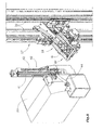
- the warehouse of the FIG. 1 illustrated first embodiment has a goods receiving machine 10, are entered into the goods, as indicated by the arrow 11.
- the goods are entered randomly. This means that the goods are filled out of order, for example in a funnel and then separated.
- the goods receiving machine contains a sensor for identifying the individual goods on the basis of a barcode, data matrix code or a transponder attached to the goods.
- a warehouse management computer then decides whether each individual goods is fed to a storage machine 12 (arrow 13) or another storage machine (arrow 14).
- the storage machine 12 is in the present case, a channel machine with multiple channels 15, in which the goods are each stacked in a row one above the other.
- the channels 15 are formed on inclined shelves or in vertical tubes, in each case the lowest object can be removed and then slip the other objects down.
- the storage machine 12 corresponds in its construction substantially to that of EP 0 991 037 B1 (Willach ).
- a manipulator 17 At the output end of the channel structure is a free space 16 in which a manipulator 17 is controlled to move.
- the manipulator 17 has a goods carrier 18 which can be moved to the discharge end of a channel 15 to take over there an object to be dispensed from the respective channel 15.
- the manipulator 17 is a paging manipulator.
- the product carrier 18 is either a gripper or a support surface with rear support function.
- the manipulator 17 brings the article 19 to a treatment position at which a treatment device 20 is located.
- the treatment device 20 is here a Labeling machine that attaches a custom printed label on the article 19.
- the object 19 is pressed by the manipulator 17, for example, against the labeling machine 35.
- the manipulator 17 brings the article 19 to an issue position 21 or 22.
- a conveyor 23 or 24 leads to a particular workstation where the order for delivery of the article in question has been entered into the computer system.
- the automatic storage machine 12 has a storage manipulator 26, which is movable in a free space 27 on the feed side of the channels 15 to store goods in the channels 15.
- the storage manipulator 26 picks up the goods from a transfer station from the goods receiving machine 10. Therefore, the entire flow of goods of the automatic warehouse from the goods receiving to the goods issue is under the control and control of the warehouse management computer, so that confusion or permutations of goods can not practically occur.
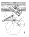
- a storage machine 12 is also available.
- FIG. 2 the front view is shown.
- a goods receiving machine is not provided here.
- the objects are stored from the back.
- the storage machine contains numerous channels 15. Channels 15 arranged next to one another are each separated from one another by a longitudinally upright standing metal sheet.
- the channels 15 have the front end slope. At the front end of each channel is a stop element.
- the manipulator 17 Before the discharge ends of the channels 15, the manipulator 17 is movable. The movement is under the control of a warehouse management computer.
- the manipulator 17 has a goods carrier 18, which is movable on vertical rails 30 movable.
- the product carrier has an inclined support surface on which the lowest object of a channel 15 can slide down.
- the product carrier 18 of the manipulator then travels behind an output window 31 to deliver the article to the outside. This is the usual functional sequence of the state of the art storage machines of FIG. 2 ,
- the front side of the automatic storage machine 12 is preceded by a treatment device 20.
- a treatment device 20 This has a device base 33, in which a compressed air generator and control devices are housed, and under a transparent hood 34, a labeling machine 35 with printer.
- FIG. 4 shows that the device base 33 is pivotable relative to the housing of the storage machine 12 about a vertical axis, so that the working machine facing the working side facing the treatment device 20 is accessible for maintenance purposes.
- a window 38 visible in a windshield 39 of the automatic storage machine. Through this window 38, the applicator of the treatment device can access to label the article before its output from the storage machine.
- a hinge 36 is provided for the attachment of the treatment device 20 ( FIG. 3 ) and a locking device 37 ( FIG. 4 ).
- the applicator 40 On the housing of the labeling machine 35, the applicator 40 is attached. This has a fixed rigid support arm 41 and a pivot arm 42. The pivot arm 42 is attached to a hinge 43 at the upper end of the support arm 41. A linear drive 44, in the present case a pneumatic cylinder, is attached to the support arm 41 and its rod engages hinged to the pivot arm 42. The linear actuator 44 pivots the pivot arm 42 between a Retraction position ( FIG. 5 ) and a working position ( FIG. 6 ). At the lower end of the pivot arm 42 is a stamp plate 45 which is movable by a provided on the pivot arm 42 linear drive 46 in the longitudinal direction of the pivot arm. This stamp plate 45 includes a suction device (not shown) for sucking and holding a label printed by the printer.
- a suction device not shown
- the stamp plate 45 In the working position of the swivel arm ( FIG. 6 ), the stamp plate 45 is parallel to the bottom of the product carrier 18 on which the article G rests. Consequently, the label can be transferred to the object G by operating the linear actuator 46.
- the manipulator 17 then moves the product carrier behind an output window 31 (FIG. FIG. 2 ), whereby the item is dispensed from the storage machine.
- FIG. 7 shows the goods carrier 18 located in the treatment position BP with the object G thereon, on which the label E has been attached in a predetermined orientation.
- the label E is a self-adhesive label that is printed on the printer while it is on a carrier strip. The printed label is subsequently removed from the carrier strip and then taken over by the stamp plate 45.
- FIG. 8 shows the product carrier 18, which is moved along the vertical guide rails 30 controlled.
- the product carrier 18 has an obliquely arranged base plate 50, which is laterally bounded by fixed side plates 51.
- a controlled pivotable flap 52 At the lower (front) end is a controlled pivotable flap 52 which can be folded down about a horizontal axis to discharge the article into the delivery window 31. The article then slides down from the floor 50 due to its gravity.
- a lifter 53 is arranged, which can be raised in a controlled manner beyond the surface of the bottom 50, in order to move one in a channel 15 (FIG. FIG. 2 ) lifting the front object. Then this object passes over the stop at the front end of the channel on the goods carrier 18th
- each guide jaw 54,55 On the floor 50 of the goods carrier guide jaws 54,55 are arranged. These are parallel to each other and they are controlled in opposite directions to each other, with the guide jaws either remove or approach from an imaginary fixed centerline.
- an inlet bevel 56,57 is articulated, the upper end of which is guided on the side wall 51.
- the inlet slopes 56, 57 effectively form a funnel, through which the object is brought into the middle position.
- the guide jaws 54,55 are driven in common by a motor.
- the guide jaws 54, 55 are moved apart stepwise or continuously until the distance is greater than the width of the article. Then the object slides between the guide jaws to the lower end stop.
- the guide jaws 54,55 then continue to diverge until an outer end position is reached.
- the guide jaws move toward each other again, wherein a centering of the object is achieved with respect to the longitudinal center axis of the goods carrier 18. In this centered position, the article is held while the label is being transferred to it.
- FIG. 9 schematically shows the second phase of the movement of the guide jaws 54,55.
- Each guide jaw is driven by a motor 58,59.
- the movement organs are for example spindle nuts, which are driven by corresponding spindles.
- Each movement member is connected to the associated jaw by a tension spring 60,61.
- the spring travel of the tension spring 60 is monitored by a sensor 62.
- the movement organs 58,59 move toward each other, so that the guide jaws 54,55 approach the packing G.
- FIG. 10 the state is shown that the guide jaws 54,55 abut the object G and press against it.
- the movement organs 58, 59 are anxious to move towards each other.
- the stamp plate consists of a padded or pressurized pad which conforms to the contour of the article. With such a stamp plate objects with flat and round surface can be labeled.
- the invention which has been explained here using the example of a slot machine, is also applicable to single-seat type automatic storage machines.
Abstract
Description
Die Erfindung betrifft ein automatisches Warenlager mit einer Vorrichtung, die einzulagernde Gegenstände identifiziert, und einem Lagerautomaten mit Manipulatorfunktionen für Einlagerung und Auslagerung.The invention relates to an automatic warehouse with a device that identifies items to be stored, and a storage machine with manipulator functions for storage and retrieval.
Automatische Warenlager sind im Stande, Waren automatisch einzulagern und automatisch auszulagern, wobei ein Lagerverwaltungsrechner den Lagerplatz bestimmt und den Aufenthaltsort der Ware bis zu deren Auslagerung speichert bzw. verfolgt. Ein Lagerautomat vom Kanaltyp ist beschrieben in
Ein Lagerautomat vom Einzelplatztyp ist beschrieben in
In
Bei Medikamentenpackungen bestehen Regelungen, die vorschreiben, dass auf der Packung der Name des Patienten sowie bestimmte Angaben über das Arzneimittel stehen, beispielsweise eine individuelle Einnahmevorschrift. Solche Informationen können mit einem Etikett an der Packung angebracht werden. Bekannt sind Etikettiermaschinen, die ein individuell bedrucktes Etikett liefern können. Solche Etiketten müssen manuell an den Packungen angebracht werden. Dies birgt die Gefahr von Verwechslungen.Regarding medications, there are regulations requiring that the name of the patient and certain information about the medicine appear on the package, for example an individual prescription. Such information may be attached to the package with a label. Known labeling machines that can deliver a custom printed label. Such labels must be manually attached to the packages. This carries the risk of confusion.
Der Erfindung liegt die Aufgabe zugrunde, ein automatisches Warenlager anzugeben, das mit einer Zusatzfunktion ausgestattet werden kann, wobei Verwechslungen der Waren oder Packungen so gut wie ausgeschlossen sind.The invention has for its object to provide an automatic warehouse that can be equipped with an additional function, with confusion of goods or packs are virtually impossible.
Das automatische Warenlager nach der vorliegenden Erfindung ist durch den Anspruch 1 bezeichnet. Es ist dadurch gekennzeichnet, dass die Manipulatorfunktion für Auslagerung das Festhalten des Gegenstandes im Wirkbereich ein Behandlungsvorrichtung umfasst.The automatic warehouse according to the present invention is characterized by
Bei dem erfindungsgemäßen Warenlager hat der Auslagerungsmanipulator, der die Gegenstände aus dem Warenlager ausgibt, nicht nur die Funktion der Warenausgabe sondern auch eine Haltefunktion im Zusammenwirken mit einer Behandlungsvorrichtung. Die Behandlungsvorrichtung dient dazu, an dem auszugebenden Gegenstand eine Bearbeitung vorzunehmen, beispielsweise das Aufkleben eines Etiketts oder das Bedrucken. Dadurch, dass die Behandlung unmittelbar bei der Ausgabe des Gegenstandes aus dem Warenlager erfolgt, sind Verwechslungen praktisch ausgeschlossen. Dies liegt daran, dass im Warenlager keine manuellen Eingriffe erfolgen und sämtliche Bewegungen vom Lagerverwaltungsrechner gesteuert sind. Daher kann jeder Position, an der sich ein Gegenstand befinden kann, die Identität des jeweiligen Gegenstandes zugeordnet werden. Anders ausgedrückt: Dem Lagerverwaltungsrechner ist jederzeit bekannt, welcher Gegenstand sich in dem Warenlager an welcher Position befindet. Dadurch wird sichergestellt, dass bei der Ausgabe eines Gegenstandes die für diesen Gegenstand vorgesehene Behandlung an dem richtigen Gegenstand verübt wird.In the warehouse according to the invention, the outsourcing manipulator, which outputs the items from the warehouse, not only the function of the goods issue but also a holding function in cooperation with a Treatment device. The treatment device serves to carry out a processing on the object to be dispensed, for example, the sticking of a label or the printing. The fact that the treatment takes place immediately upon the issue of the item from the warehouse, confusion is practically impossible. This is due to the fact that no manual intervention takes place in the warehouse and all movements are controlled by the warehouse management computer. Therefore, any position where an object can be located can be assigned the identity of the respective object. In other words, the warehouse management computer is always aware of which item is in the warehouse at which position. This will ensure that when an item is dispensed, the treatment provided for that item will be committed to the correct item.
Die Behandlungsvorrichtung ist vorzugsweise eine Etikettiermaschine oder ein Drucker. Sie ist im Stande, warenbezogene Informationen an dem ausgelagerten Gegenstand anzubringen. Solche warenbezogenen Informationen sind beispielsweise Dosiervorschriften, Warnhinweise, der Name des Kunden und ähnliches.The treatment device is preferably a labeling machine or a printer. It is able to attach goods related information to the outsourced item. Such goods-related information is for example dosing instructions, warnings, the name of the customer and the like.
Das erfindungsgemäße automatische Warenlager eignet sich insbesondere als Apothekenlager. In Apotheken sind die Waren in quaderförmigen Packungen enthalten und es gibt eine große Vielzahl unterschiedlicher Waren. Ein automatisches Apothekenlager bietet den Vorteil, dass der Pharmazeut sich vollständig dem Kunden widmen kann und nicht zum Holen der Ware in einem Lagerraum verschwinden muss. Durch ein Transportsystem wird die Ware direkt an den Verkaufsplatz befördert, wo sie bereits mit der erforderlichen individuellen Bedruckung versehen ist.The automatic warehouse according to the invention is particularly suitable as a pharmacy warehouse. In pharmacies, the goods are in cuboid packs and there is a large variety of different goods. An automated pharmacy warehouse has the advantage that the pharmacist can devote himself entirely to the customer and does not have to disappear to get the goods in a storage room. Through a transport system, the goods are transported directly to the point of sale, where it is already provided with the required individual printing.
Vorzugsweise ist ein Auslagerungsmanipulator des Lagerautomaten mit einer Stützvorrichtung zum Abstützen des entnommenen Gegenstandes während des Andrückens eines Etiketts versehen.Preferably, a storage manipulator of the storage machine is provided with a support device for supporting the removed object during the pressing of a label.
Um sicherzustellen, dass die Behandlung des Gegenstandes an der richtigen Stelle auf dem Gegenstand erfolgt, beispielsweise das Aufkleben eines Etiketts, kann eine Zentrierung des Gegenstandes vorgenommen werden. Zu diesem Zweck ist ein Warenträger des Manipulators mit seitlich bewegbaren Führungsbacken versehen, welche Gegenstände unterschiedlicher Abmessungen auf dem Warenträger zentrieren und in definierter Ausrichtung positionieren. Die Führungsbacken können gegensinnig zueinander angetrieben sein. Vorzugsweise enthält mindestens eine der Führungsbacken einen Sensor, der anspricht, wenn das Zusammenbewegen der Führungsbacken eine vorbestimmte Kraft übersteigt, und die Führungsbacken in dieser Position anhält. Der Gegenstand wird auf diese Weise in seiner zentrierten Lage festgehalten, so dass die Behandlungsvorrichtung auf ihn einwirken kann.In order to ensure that the treatment of the article takes place in the right place on the article, for example the sticking of a label, a centering of the article can be carried out. For this purpose, a goods carrier of the manipulator is provided with laterally movable guide jaws, which center objects of different dimensions on the goods carrier and position in a defined orientation. The guide jaws can be driven in opposite directions to each other. Preferably, at least one of the guide jaws includes a sensor that responds when the moving together of the guide jaws exceeds a predetermined force, and stops the guide jaws in this position. The article is held in this way in its centered position, so that the treatment device can act on him.
Vorzugsweise sind die Führungsbacken jeweils mit einer Einlaufschräge versehen. In einer ersten Phase des Positionierens eines Gegenstandes sind die Führungsbacken derart gesteuert, dass sie sich voneinander entfernen. Dadurch wird der Gegenstand, sobald er zwischen die Führungsbacken passt, gegen einen Anschlag bewegt, ohne dass der Gegenstand Gelegenheit hätte, sich auf dem Warenträger in eine andere Position zu drehen. Die konvergierenden Einlaufschrägen der Führungsbacken bilden einen sich zeitlich erweiternden Trichter, in dem der Gegenstand, wenn er in den Trichterhals passt, geordnet absinken kann. Anschließend erfolgt ein Zusammenbewegen der Führungsbacken, wobei infolge der gegensinnig synchron angetriebenen Führungsbacken der Gegenstand auf dem Warenträger zentriert wird.Preferably, the guide jaws are each provided with an inlet slope. In a first phase of positioning an article, the guide jaws are controlled so that they move away from each other. As a result, the object, as soon as it fits between the guide jaws, moves against a stop, without the object would have opportunity to turn on the goods carrier in a different position. The converging inlet slopes of the guide jaws form a time-expanding funnel, in which the object, when it fits in the funnel neck, can sink in an orderly manner. Subsequently, a moving together of the guide jaws, which is centered as a result of the oppositely synchronously driven guide jaws of the article on the goods carrier.
Die Behandlungsvorrichtung enthält einen Applikator, vorzugsweise mit einer Stempelplatte und einem die Stempelplatte tragenden Schwenkarm.The treatment device contains an applicator, preferably with a stamp plate and a swivel arm carrying the stamp plate.
Die Behandlungsvorrichtung ist zweckmäßigerweise vor der Vorderseite des Lagerautomaten fixiert und der Manipulator des Lagerautomaten kann eine gespeicherte Behandlungsposition anfahren, in der die Behandlungsvorrichtung an den auf dem Manipulator liegenden Gegenstand zugreifen kann.The treatment device is expediently fixed in front of the front of the automatic storage machine and the manipulator of the automatic storage machine can approach a stored treatment position in which the treatment device can access the object lying on the manipulator.
Die Identifizierung der Gegenstände erfolgt vorzugsweise bei deren Einlagerung durch einen entsprechenden Sensor, beispielsweise einen Barcodeleser. Der Sensor kann in einem Warenannahmeautomaten, wie er in
Es besteht auch die Möglichkeit, dass die Behandlungsvorrichtung ein Drucker ist. In diesem Fall wird ein an dem Gegenstand vorgesehenes Feld mit einer Bedruckung versehen, beispielsweise durch einen Tintenstrahldrucker. Mit dem Etikett oder der Bedruckung kann auch der Name der Apotheke aufgebracht werden.There is also the possibility that the treatment device is a printer. In this case, a field provided on the article is imprinted, for example by an inkjet printer. With the label or the printing, the name of the pharmacy can be applied.
Im Folgenden werden unter Bezugnahme auf die Zeichnungen Ausführungsbeispiele der Erfindung näher erläutert.In the following, embodiments of the invention will be explained in more detail with reference to the drawings.
Es zeigen:
Figur 1- ein erstes Ausführungsbeispiel eines automatischen Warenlagers nach der Erfindung,
- Figur 2
- bei einem zweiten Ausführungsbeispiel eine Frontansicht des Lagerautomaten, jedoch ohne vorgesetzte Behandlungsvorrichtung,
- Figur 3
- die vor dem Lagerautomaten befestigte oder fixierte Behandlungsvorrichtung,
- Figur 4
- die Schwenkbarkeit der Behandlungsvorrichtung relativ zu dem Lagerautomaten zum Zwecke der Wartung und des Austausches von Etikettenrollen,
- Figur 5
- den Warenträger des Manipulators in der Behandlungsposition mit dem davor angeordneten Applikator der Behandlungsvorrichtung,
- Figur 6
- den Applikator der Behandlungsvorrichtung beim Übertragen eines Etiketts auf einen von dem Warenträger gehaltenen Gegenstand,
- Figur 7
- das Zurückfahren des Applikators nach dem Übertragen des Etiketts auf den Gegenstand,
- Figur 8
- den Warenträger des Manipulators mit den seitlich bewegbaren Führungsbacken,
- Figur 9
- eine Schemazeichnung der zweiten Phase des Positionierens eines Gegenstandes durch Gegeneinanderbewegung der Führungsbacken und
Figur 10- das Ansprechen des Sensors, wenn der Druck der Führungsbacken einen vorbestimmten Wert übersteigt.
- FIG. 1
- A first embodiment of an automatic warehouse according to the invention,
- FIG. 2
- in a second embodiment, a front view of the storage machine, but without superior treatment device,
- FIG. 3
- the treatment device attached or fixed in front of the storage machine,
- FIG. 4
- the pivotability of the treatment device relative to the automatic storage machine for the purpose of maintenance and replacement of label rolls,
- FIG. 5
- the goods carrier of the manipulator in the treatment position with the previously arranged applicator of the treatment device,
- FIG. 6
- the applicator of the treatment device when transferring a label to an object held by the product carrier,
- FIG. 7
- retracting the applicator after transferring the label to the article,
- FIG. 8
- the product carrier of the manipulator with the laterally movable guide jaws,
- FIG. 9
- a schematic drawing of the second phase of positioning an article by opposing movement of the guide jaws and
- FIG. 10
- the response of the sensor when the pressure of the guide jaws exceeds a predetermined value.
Das Warenlager des in
Der Lagerautomat 12 ist im vorliegenden Fall ein Kanalautomat mit mehreren Kanälen 15, in denen die Waren jeweils in einer Reihe übereinander liegend gestapelt werden. Beispielsweise sind die Kanäle 15 auf Schrägfachböden oder in vertikalen Röhren ausgebildet, wobei jeweils der unterste Gegenstand entnommen werden kann und die anderen Gegenstände dann nach unten nachrutschen.The
Der Lagerautomat 12 entspricht in seinem Aufbau im wesentlichen demjenigen von
Der Lagerautomat 12 weist einen Einlagerungsmanipulator 26 auf, der in einem Freiraum 27 an der Beschickungsseite der Kanäle 15 gesteuert verfahrbar ist, um Waren in die Kanäle 15 einzulagern. Der Einlagerungsmanipulator 26 holt die Waren von einer Übergabestation vom Warenannahmeautomaten 10 ab. Daher ist der gesamte Warenfluss des automatischen Warenlagers von der Warenannahme bis zur Warenausgabe unter Steuerung und Kontrolle des Lagerverwaltungsrechners, so dass Verwechslungen bzw. Vertauschungen von Waren praktisch nicht vorkommen können.The
Bei dem zweiten Ausführungsbeispiel, das in den
Vor den Abgabeenden der Kanäle 15 ist der Manipulator 17 bewegbar. Die Bewegung erfolgt unter Steuerung durch einen Lagerverwaltungsrechner. Der Manipulator 17 weist einen Warenträger 18 auf, der an vertikalen Schienen 30 gesteuert verfahrbar ist. Der Warenträger hat eine schräge Tragfläche, auf die der unterste Gegenstand eines Kanals 15 hinabgleiten kann. Der Warenträger 18 des Manipulators fährt dann hinter ein Ausgabefenster 31, um den Gegenstand nach außen abzugeben. Dies ist der übliche Funktionsablauf des dem Stand der Technik entsprechenden Lagerautomaten von
Erfindungsgemäß ist der Vorderseite des Lagerautomaten 12 eine Behandlungsvorrichtung 20 vorgesetzt. Diese weist einen Gerätesockel 33 auf, in dem ein Drucklufterzeuger sowie Steuereinrichtungen untergebracht sind, und unter einer durchsichtigen Haube 34 eine Etikettiermaschine 35 mit Drucker.
In den
An dem Gehäuse der Etikettiermaschine 35 ist der Applikator 40 befestigt. Dieser weist einen ortsfesten starren Tragarm 41 und einen Schwenkarm 42 auf. Der Schwenkarm 42 ist mit einem Gelenk 43 am oberen Ende des Tragarms 41 befestigt. Ein Linearantrieb 44, im vorliegenden Fall ein Pneumatikzylinder, ist an dem Tragarm 41 befestigt und seine Stange greift gelenkig an dem Schwenkarm 42 an. Der Linearantrieb 44 verschwenkt den Schwenkarm 42 zwischen einer Rückzugsposition (
An dem oberen Ende des Bodens 50 ist ein Heber 53 angeordnet, der gesteuert über die Fläche des Bodens 50 hinaus angehoben werden kann, um einen in einem Kanal 15 (
Auf dem Boden 50 des Warenträgers sind Führungsbacken 54,55 angeordnet. Diese verlaufen parallel zueinander und sie sind gegensinnig zueinander gesteuert, wobei sich die Führungsbacken von einer gedachten feststehenden Mittellinie entweder entfernen oder sich annähern. An dem oberen Ende jeder Führungsbacke 54,55 ist eine Einlaufschräge 56,57 angelenkt, deren oberes Ende an der Seitenwand 51 geführt ist. Die Einlaufschrägen 56,57 bilden gewissermaßen einen Trichter, durch den der Gegenstand in die Mittellage gebracht wird. Die Führungsbacken 54,55 sind von einem Motor gemeinsam angetrieben. Wenn ein Gegenstand auf den Warenträger 18 übernommen wurde, werden die Führungsbacken 54,55 schrittweise oder kontinuierlich auseinanderbewegt, bis der Abstand größer ist als die Breite des Gegenstandes. Dann gleitet der Gegenstand zwischen den Führungsbacken bis zum unteren Endanschlag. Auf diese Weise wird verhindert, dass der Gegenstand sich verdreht oder seine Orientierung verändert. Die Führungsbacken 54,55 fahren dann weiter auseinander, bis eine äußere Endposition erreicht wird. In einer zweiten Phase bewegen sich die Führungsbacken wieder aufeinander zu, wobei eine Zentrierung des Gegenstandes in Bezug auf die Längsmittelachse des Warenträgers 18 erreicht wird. In dieser zentrierten Position wird der Gegenstand festgehalten, während das Etikett auf ihn übertragen wird.On the
Mit der beschriebenen Zentriervorrichtung können auch zylindrische Packungen zentriert bzw. behandelt werden. In diesem Fall besteht die Stempelplatte aus einem gepolsterten oder druckbeaufschlagten Kissen, das sich der Kontur des Gegenstandes anpasst. Mit einer derartigen Stempelplatte können Gegenstände mit ebener und mit runder Oberfläche etikettiert werden.With the described centering and cylindrical packages can be centered or treated. In this case, the stamp plate consists of a padded or pressurized pad which conforms to the contour of the article. With such a stamp plate objects with flat and round surface can be labeled.
Die Erfindung, die hier am Beispiel eines Kanalautomaten erläutert wurde, ist auch bei Lagerautomaten vom Einzelplatz-Typ anwendbar.The invention, which has been explained here using the example of a slot machine, is also applicable to single-seat type automatic storage machines.
Claims (11)
dadurch gekennzeichnet,
dass die Manipulatorfunktion für Auslagerung das Festhalten des Gegenstandes (19) im Wirkbereich einer Behandlungsvorrichtung (20) umfasst.Automatic warehouse with a device that identifies items to be stored, and a storage machine (12) with manipulator functions for outsourcing,
characterized,
in that the manipulator function for removal comprises the retention of the object (19) in the effective region of a treatment device (20).
Applications Claiming Priority (1)
| Application Number | Priority Date | Filing Date | Title |
|---|---|---|---|
| DE202007013104U DE202007013104U1 (en) | 2007-09-19 | 2007-09-19 | Automatic warehouse |
Publications (3)
| Publication Number | Publication Date |
|---|---|
| EP2040230A2 true EP2040230A2 (en) | 2009-03-25 |
| EP2040230A3 EP2040230A3 (en) | 2010-03-17 |
| EP2040230B1 EP2040230B1 (en) | 2019-05-08 |
Family
ID=38690747
Family Applications (1)
| Application Number | Title | Priority Date | Filing Date |
|---|---|---|---|
| EP08164621.8A Active EP2040230B1 (en) | 2007-09-19 | 2008-09-18 | Automatic goods dispenser |
Country Status (2)
| Country | Link |
|---|---|
| EP (1) | EP2040230B1 (en) |
| DE (1) | DE202007013104U1 (en) |
Cited By (5)
| Publication number | Priority date | Publication date | Assignee | Title |
|---|---|---|---|---|
| WO2012143453A1 (en) * | 2011-04-19 | 2012-10-26 | Proces-Data A/S | Apparatus and method for managing stored goods such as packaged tobacco products |
| WO2012143454A1 (en) * | 2011-04-19 | 2012-10-26 | Proces-Data A/S | Apparatus and method for storing and dispensing goods such as packaged tobacco products |
| CN109830046A (en) * | 2019-01-22 | 2019-05-31 | 长沙大荒机器人有限公司 | Unmanned supermarket's vending system |
| CN109956249A (en) * | 2019-02-20 | 2019-07-02 | 浙江恒天凡腾科技股份有限公司 | A kind of intelligence textile warehousing system |
| CN115346318A (en) * | 2022-10-19 | 2022-11-15 | 航信德利信息系统(上海)有限公司 | Escort processing system and use method thereof |
Families Citing this family (1)
| Publication number | Priority date | Publication date | Assignee | Title |
|---|---|---|---|---|
| DE202009001446U1 (en) | 2009-02-10 | 2010-07-01 | Gebr. Willach Gmbh | storage Machine |
Citations (4)
| Publication number | Priority date | Publication date | Assignee | Title |
|---|---|---|---|---|
| EP0991037B1 (en) | 1998-10-01 | 2003-10-29 | GEBR. WILLACH GmbH | Dispensing machine with a common delivery handler |
| EP1407984B1 (en) | 2002-10-09 | 2006-03-01 | GEBR. WILLACH GmbH | Shelf storage with movable racks |
| EP1409376B1 (en) | 2001-07-26 | 2007-03-28 | Dirk Rolf Beils | Method and device for conducting the computer-controlled storage and removal of small-piece products |
| EP1900654A1 (en) | 2006-09-12 | 2008-03-19 | GEBR. WILLACH GmbH | Automatic goods receiving device |
Family Cites Families (3)
| Publication number | Priority date | Publication date | Assignee | Title |
|---|---|---|---|---|
| US6176392B1 (en) * | 1997-12-05 | 2001-01-23 | Mckesson Automated Prescription Systems, Inc. | Pill dispensing system |
| US6892512B2 (en) * | 2002-08-07 | 2005-05-17 | Medco Health Solutions, Inc. | Automated prescription filling system/method with automated labeling and packaging system/method automated order consolidation system/method |
| US7689318B2 (en) * | 2005-08-19 | 2010-03-30 | Lonnie Draper | Inventory control and prescription dispensing system |
-
2007
- 2007-09-19 DE DE202007013104U patent/DE202007013104U1/en not_active Expired - Lifetime
-
2008
- 2008-09-18 EP EP08164621.8A patent/EP2040230B1/en active Active
Patent Citations (4)
| Publication number | Priority date | Publication date | Assignee | Title |
|---|---|---|---|---|
| EP0991037B1 (en) | 1998-10-01 | 2003-10-29 | GEBR. WILLACH GmbH | Dispensing machine with a common delivery handler |
| EP1409376B1 (en) | 2001-07-26 | 2007-03-28 | Dirk Rolf Beils | Method and device for conducting the computer-controlled storage and removal of small-piece products |
| EP1407984B1 (en) | 2002-10-09 | 2006-03-01 | GEBR. WILLACH GmbH | Shelf storage with movable racks |
| EP1900654A1 (en) | 2006-09-12 | 2008-03-19 | GEBR. WILLACH GmbH | Automatic goods receiving device |
Cited By (6)
| Publication number | Priority date | Publication date | Assignee | Title |
|---|---|---|---|---|
| WO2012143453A1 (en) * | 2011-04-19 | 2012-10-26 | Proces-Data A/S | Apparatus and method for managing stored goods such as packaged tobacco products |
| WO2012143454A1 (en) * | 2011-04-19 | 2012-10-26 | Proces-Data A/S | Apparatus and method for storing and dispensing goods such as packaged tobacco products |
| CN109830046A (en) * | 2019-01-22 | 2019-05-31 | 长沙大荒机器人有限公司 | Unmanned supermarket's vending system |
| CN109956249A (en) * | 2019-02-20 | 2019-07-02 | 浙江恒天凡腾科技股份有限公司 | A kind of intelligence textile warehousing system |
| CN115346318A (en) * | 2022-10-19 | 2022-11-15 | 航信德利信息系统(上海)有限公司 | Escort processing system and use method thereof |
| CN115346318B (en) * | 2022-10-19 | 2023-01-03 | 航信德利信息系统(上海)有限公司 | Escort processing system and use method thereof |
Also Published As
| Publication number | Publication date |
|---|---|
| DE202007013104U1 (en) | 2007-11-15 |
| EP2040230A3 (en) | 2010-03-17 |
| EP2040230B1 (en) | 2019-05-08 |
Similar Documents
| Publication | Publication Date | Title |
|---|---|---|
| EP3012198B2 (en) | Device and method for handling items | |
| AT391671B (en) | METHOD AND DEVICE FOR AUTOMATIC STACKING, STORAGE AND REMOVAL OF ITEMS | |
| EP2040230B1 (en) | Automatic goods dispenser | |
| DE2124984A1 (en) | ||
| EP3592668A1 (en) | Method for order-picking goods and order-picking system for carrying out the method | |
| DE60021291T2 (en) | Machine for packaging tablets | |
| WO2018024311A1 (en) | Order-picking system | |
| DE102012025163A1 (en) | Device for commissioning of goods from source containers, has longitudinal conveyers conveying source containers to commissioning ends, and commissioning rig whose planes are formed as driving planes for movable transportation of robots | |
| DE102007007411A1 (en) | Storage method for packets of drugs/medicines delivered unsorted in collecting boxes stores packets in a computer-controlled pharmacy store | |
| EP3030492B1 (en) | Labelling device, labelling system and method for providing a product with a label | |
| EP3501676A1 (en) | Bottle cleaning device | |
| EP3377427A1 (en) | Conveying system | |
| DE20122458U1 (en) | Method for computer-controlled storage and removal/picking of small packaged products uses shelves with multiple shelf compartments above and next to each other and a computer-controlled handling device. | |
| WO1996018560A1 (en) | Method and device for handling and stacking pressed bales | |
| EP2011747A2 (en) | Combined warehouse | |
| DE102009052345B4 (en) | Automated picking device and method for automated picking of books, media, brochures and similar items | |
| EP0416627B1 (en) | Method and device for storing goods and automatically selecting them from shelves in large scale stores | |
| EP1524209B1 (en) | Method and device for simultaneously retrieving a plurality of articles in a shelf storage | |
| EP2163492B1 (en) | Combined warehouse | |
| DE2435671C3 (en) | Method and device for handling and storing elongated objects | |
| EP1190964B1 (en) | Method for storing and retrieving of articles | |
| DE102022114943B4 (en) | Repackaging device for repackaging medicaments in tablet form and method for operating a repackaging device | |
| EP1115636B1 (en) | Method and device for supplying, positioning, storing and/or changing containers | |
| DE19635032C1 (en) | System preventing breakdown of computer-controlled automatic rack storage system | |
| EP0686582B1 (en) | Installation for storing and placing at disposal small parts and method for taking out store goods |
Legal Events
| Date | Code | Title | Description |
|---|---|---|---|
| PUAI | Public reference made under article 153(3) epc to a published international application that has entered the european phase |
Free format text: ORIGINAL CODE: 0009012 |
|
| AK | Designated contracting states |
Kind code of ref document: A2 Designated state(s): AT BE BG CH CY CZ DE DK EE ES FI FR GB GR HR HU IE IS IT LI LT LU LV MC MT NL NO PL PT RO SE SI SK TR |
|
| AX | Request for extension of the european patent |
Extension state: AL BA MK RS |
|
| PUAL | Search report despatched |
Free format text: ORIGINAL CODE: 0009013 |
|
| AK | Designated contracting states |
Kind code of ref document: A3 Designated state(s): AT BE BG CH CY CZ DE DK EE ES FI FR GB GR HR HU IE IS IT LI LT LU LV MC MT NL NO PL PT RO SE SI SK TR |
|
| AX | Request for extension of the european patent |
Extension state: AL BA MK RS |
|
| 17P | Request for examination filed |
Effective date: 20100910 |
|
| AKX | Designation fees paid |
Designated state(s): AT BE BG CH CY CZ DE DK EE ES FI FR GB GR HR HU IE IS IT LI LT LU LV MC MT NL NO PL PT RO SE SI SK TR |
|
| 17Q | First examination report despatched |
Effective date: 20101115 |
|
| STAA | Information on the status of an ep patent application or granted ep patent |
Free format text: STATUS: EXAMINATION IS IN PROGRESS |
|
| RIC1 | Information provided on ipc code assigned before grant |
Ipc: G07F 17/00 20060101ALI20181024BHEP Ipc: B65G 47/90 20060101ALI20181024BHEP Ipc: G07F 11/32 20060101AFI20181024BHEP Ipc: G07F 11/16 20060101ALI20181024BHEP Ipc: B65G 1/137 20060101ALI20181024BHEP |
|
| GRAP | Despatch of communication of intention to grant a patent |
Free format text: ORIGINAL CODE: EPIDOSNIGR1 |
|
| STAA | Information on the status of an ep patent application or granted ep patent |
Free format text: STATUS: GRANT OF PATENT IS INTENDED |
|
| INTG | Intention to grant announced |
Effective date: 20181213 |
|
| GRAS | Grant fee paid |
Free format text: ORIGINAL CODE: EPIDOSNIGR3 |
|
| GRAA | (expected) grant |
Free format text: ORIGINAL CODE: 0009210 |
|
| STAA | Information on the status of an ep patent application or granted ep patent |
Free format text: STATUS: THE PATENT HAS BEEN GRANTED |
|
| AK | Designated contracting states |
Kind code of ref document: B1 Designated state(s): AT BE BG CH CY CZ DE DK EE ES FI FR GB GR HR HU IE IS IT LI LT LU LV MC MT NL NO PL PT RO SE SI SK TR |
|
| REG | Reference to a national code |
Ref country code: GB Ref legal event code: FG4D Free format text: NOT ENGLISH |
|
| REG | Reference to a national code |
Ref country code: CH Ref legal event code: EP Ref country code: AT Ref legal event code: REF Ref document number: 1131413 Country of ref document: AT Kind code of ref document: T Effective date: 20190515 |
|
| REG | Reference to a national code |
Ref country code: DE Ref legal event code: R096 Ref document number: 502008016741 Country of ref document: DE |
|
| REG | Reference to a national code |
Ref country code: IE Ref legal event code: FG4D Free format text: LANGUAGE OF EP DOCUMENT: GERMAN |
|
| REG | Reference to a national code |
Ref country code: NL Ref legal event code: FP |
|
| REG | Reference to a national code |
Ref country code: LT Ref legal event code: MG4D |
|
| PG25 | Lapsed in a contracting state [announced via postgrant information from national office to epo] |
Ref country code: PT Free format text: LAPSE BECAUSE OF FAILURE TO SUBMIT A TRANSLATION OF THE DESCRIPTION OR TO PAY THE FEE WITHIN THE PRESCRIBED TIME-LIMIT Effective date: 20190908 Ref country code: ES Free format text: LAPSE BECAUSE OF FAILURE TO SUBMIT A TRANSLATION OF THE DESCRIPTION OR TO PAY THE FEE WITHIN THE PRESCRIBED TIME-LIMIT Effective date: 20190508 Ref country code: HR Free format text: LAPSE BECAUSE OF FAILURE TO SUBMIT A TRANSLATION OF THE DESCRIPTION OR TO PAY THE FEE WITHIN THE PRESCRIBED TIME-LIMIT Effective date: 20190508 Ref country code: SE Free format text: LAPSE BECAUSE OF FAILURE TO SUBMIT A TRANSLATION OF THE DESCRIPTION OR TO PAY THE FEE WITHIN THE PRESCRIBED TIME-LIMIT Effective date: 20190508 Ref country code: NO Free format text: LAPSE BECAUSE OF FAILURE TO SUBMIT A TRANSLATION OF THE DESCRIPTION OR TO PAY THE FEE WITHIN THE PRESCRIBED TIME-LIMIT Effective date: 20190808 Ref country code: FI Free format text: LAPSE BECAUSE OF FAILURE TO SUBMIT A TRANSLATION OF THE DESCRIPTION OR TO PAY THE FEE WITHIN THE PRESCRIBED TIME-LIMIT Effective date: 20190508 Ref country code: LT Free format text: LAPSE BECAUSE OF FAILURE TO SUBMIT A TRANSLATION OF THE DESCRIPTION OR TO PAY THE FEE WITHIN THE PRESCRIBED TIME-LIMIT Effective date: 20190508 |
|
| PG25 | Lapsed in a contracting state [announced via postgrant information from national office to epo] |
Ref country code: LV Free format text: LAPSE BECAUSE OF FAILURE TO SUBMIT A TRANSLATION OF THE DESCRIPTION OR TO PAY THE FEE WITHIN THE PRESCRIBED TIME-LIMIT Effective date: 20190508 Ref country code: BG Free format text: LAPSE BECAUSE OF FAILURE TO SUBMIT A TRANSLATION OF THE DESCRIPTION OR TO PAY THE FEE WITHIN THE PRESCRIBED TIME-LIMIT Effective date: 20190808 Ref country code: GR Free format text: LAPSE BECAUSE OF FAILURE TO SUBMIT A TRANSLATION OF THE DESCRIPTION OR TO PAY THE FEE WITHIN THE PRESCRIBED TIME-LIMIT Effective date: 20190809 |
|
| PG25 | Lapsed in a contracting state [announced via postgrant information from national office to epo] |
Ref country code: EE Free format text: LAPSE BECAUSE OF FAILURE TO SUBMIT A TRANSLATION OF THE DESCRIPTION OR TO PAY THE FEE WITHIN THE PRESCRIBED TIME-LIMIT Effective date: 20190508 Ref country code: DK Free format text: LAPSE BECAUSE OF FAILURE TO SUBMIT A TRANSLATION OF THE DESCRIPTION OR TO PAY THE FEE WITHIN THE PRESCRIBED TIME-LIMIT Effective date: 20190508 Ref country code: SK Free format text: LAPSE BECAUSE OF FAILURE TO SUBMIT A TRANSLATION OF THE DESCRIPTION OR TO PAY THE FEE WITHIN THE PRESCRIBED TIME-LIMIT Effective date: 20190508 Ref country code: RO Free format text: LAPSE BECAUSE OF FAILURE TO SUBMIT A TRANSLATION OF THE DESCRIPTION OR TO PAY THE FEE WITHIN THE PRESCRIBED TIME-LIMIT Effective date: 20190508 Ref country code: CZ Free format text: LAPSE BECAUSE OF FAILURE TO SUBMIT A TRANSLATION OF THE DESCRIPTION OR TO PAY THE FEE WITHIN THE PRESCRIBED TIME-LIMIT Effective date: 20190508 |
|
| REG | Reference to a national code |
Ref country code: DE Ref legal event code: R097 Ref document number: 502008016741 Country of ref document: DE |
|
| PG25 | Lapsed in a contracting state [announced via postgrant information from national office to epo] |
Ref country code: IT Free format text: LAPSE BECAUSE OF FAILURE TO SUBMIT A TRANSLATION OF THE DESCRIPTION OR TO PAY THE FEE WITHIN THE PRESCRIBED TIME-LIMIT Effective date: 20190508 |
|
| PLBE | No opposition filed within time limit |
Free format text: ORIGINAL CODE: 0009261 |
|
| STAA | Information on the status of an ep patent application or granted ep patent |
Free format text: STATUS: NO OPPOSITION FILED WITHIN TIME LIMIT |
|
| PG25 | Lapsed in a contracting state [announced via postgrant information from national office to epo] |
Ref country code: TR Free format text: LAPSE BECAUSE OF FAILURE TO SUBMIT A TRANSLATION OF THE DESCRIPTION OR TO PAY THE FEE WITHIN THE PRESCRIBED TIME-LIMIT Effective date: 20190508 |
|
| 26N | No opposition filed |
Effective date: 20200211 |
|
| PG25 | Lapsed in a contracting state [announced via postgrant information from national office to epo] |
Ref country code: PL Free format text: LAPSE BECAUSE OF FAILURE TO SUBMIT A TRANSLATION OF THE DESCRIPTION OR TO PAY THE FEE WITHIN THE PRESCRIBED TIME-LIMIT Effective date: 20190508 |
|
| PG25 | Lapsed in a contracting state [announced via postgrant information from national office to epo] |
Ref country code: SI Free format text: LAPSE BECAUSE OF FAILURE TO SUBMIT A TRANSLATION OF THE DESCRIPTION OR TO PAY THE FEE WITHIN THE PRESCRIBED TIME-LIMIT Effective date: 20190508 Ref country code: MC Free format text: LAPSE BECAUSE OF FAILURE TO SUBMIT A TRANSLATION OF THE DESCRIPTION OR TO PAY THE FEE WITHIN THE PRESCRIBED TIME-LIMIT Effective date: 20190508 |
|
| REG | Reference to a national code |
Ref country code: CH Ref legal event code: PL |
|
| PG25 | Lapsed in a contracting state [announced via postgrant information from national office to epo] |
Ref country code: CH Free format text: LAPSE BECAUSE OF NON-PAYMENT OF DUE FEES Effective date: 20190930 Ref country code: LI Free format text: LAPSE BECAUSE OF NON-PAYMENT OF DUE FEES Effective date: 20190930 Ref country code: LU Free format text: LAPSE BECAUSE OF NON-PAYMENT OF DUE FEES Effective date: 20190918 Ref country code: IE Free format text: LAPSE BECAUSE OF NON-PAYMENT OF DUE FEES Effective date: 20190918 |
|
| REG | Reference to a national code |
Ref country code: BE Ref legal event code: MM Effective date: 20190930 |
|
| PG25 | Lapsed in a contracting state [announced via postgrant information from national office to epo] |
Ref country code: BE Free format text: LAPSE BECAUSE OF NON-PAYMENT OF DUE FEES Effective date: 20190930 |
|
| PG25 | Lapsed in a contracting state [announced via postgrant information from national office to epo] |
Ref country code: FR Free format text: LAPSE BECAUSE OF NON-PAYMENT OF DUE FEES Effective date: 20190930 |
|
| REG | Reference to a national code |
Ref country code: AT Ref legal event code: MM01 Ref document number: 1131413 Country of ref document: AT Kind code of ref document: T Effective date: 20190918 |
|
| PG25 | Lapsed in a contracting state [announced via postgrant information from national office to epo] |
Ref country code: AT Free format text: LAPSE BECAUSE OF NON-PAYMENT OF DUE FEES Effective date: 20190918 |
|
| PG25 | Lapsed in a contracting state [announced via postgrant information from national office to epo] |
Ref country code: CY Free format text: LAPSE BECAUSE OF FAILURE TO SUBMIT A TRANSLATION OF THE DESCRIPTION OR TO PAY THE FEE WITHIN THE PRESCRIBED TIME-LIMIT Effective date: 20190508 |
|
| PG25 | Lapsed in a contracting state [announced via postgrant information from national office to epo] |
Ref country code: IS Free format text: LAPSE BECAUSE OF FAILURE TO SUBMIT A TRANSLATION OF THE DESCRIPTION OR TO PAY THE FEE WITHIN THE PRESCRIBED TIME-LIMIT Effective date: 20190908 |
|
| PG25 | Lapsed in a contracting state [announced via postgrant information from national office to epo] |
Ref country code: MT Free format text: LAPSE BECAUSE OF FAILURE TO SUBMIT A TRANSLATION OF THE DESCRIPTION OR TO PAY THE FEE WITHIN THE PRESCRIBED TIME-LIMIT Effective date: 20190508 Ref country code: HU Free format text: LAPSE BECAUSE OF FAILURE TO SUBMIT A TRANSLATION OF THE DESCRIPTION OR TO PAY THE FEE WITHIN THE PRESCRIBED TIME-LIMIT; INVALID AB INITIO Effective date: 20080918 |
|
| PGFP | Annual fee paid to national office [announced via postgrant information from national office to epo] |
Ref country code: NL Payment date: 20220922 Year of fee payment: 15 Ref country code: GB Payment date: 20220927 Year of fee payment: 15 Ref country code: DE Payment date: 20220825 Year of fee payment: 15 |