EP2040054B1 - Method and apparatus for leak testing closed containers - Google Patents
Method and apparatus for leak testing closed containers Download PDFInfo
- Publication number
- EP2040054B1 EP2040054B1 EP09150253.4A EP09150253A EP2040054B1 EP 2040054 B1 EP2040054 B1 EP 2040054B1 EP 09150253 A EP09150253 A EP 09150253A EP 2040054 B1 EP2040054 B1 EP 2040054B1
- Authority
- EP
- European Patent Office
- Prior art keywords
- signal
- container
- force
- biasing
- difference
- Prior art date
- Legal status (The legal status is an assumption and is not a legal conclusion. Google has not performed a legal analysis and makes no representation as to the accuracy of the status listed.)
- Expired - Lifetime
Links
- 238000012360 testing method Methods 0.000 title claims abstract description 91
- 238000000034 method Methods 0.000 title claims description 50
- 238000006243 chemical reaction Methods 0.000 claims description 19
- 238000005259 measurement Methods 0.000 claims description 8
- 238000012544 monitoring process Methods 0.000 claims description 8
- 238000005070 sampling Methods 0.000 claims description 7
- IJGRMHOSHXDMSA-UHFFFAOYSA-N Atomic nitrogen Chemical compound N#N IJGRMHOSHXDMSA-UHFFFAOYSA-N 0.000 claims description 6
- 238000012935 Averaging Methods 0.000 claims description 6
- 239000007788 liquid Substances 0.000 claims description 6
- 238000004140 cleaning Methods 0.000 claims description 4
- 230000001419 dependent effect Effects 0.000 claims description 4
- 238000011010 flushing procedure Methods 0.000 claims description 4
- 239000007789 gas Substances 0.000 claims description 4
- 229910052757 nitrogen Inorganic materials 0.000 claims description 3
- 238000010438 heat treatment Methods 0.000 claims description 2
- 238000002847 impedance measurement Methods 0.000 claims 2
- 238000010586 diagram Methods 0.000 description 6
- 238000004519 manufacturing process Methods 0.000 description 4
- 238000001514 detection method Methods 0.000 description 3
- 230000000630 rising effect Effects 0.000 description 3
- 230000006835 compression Effects 0.000 description 2
- 238000007906 compression Methods 0.000 description 2
- 238000009826 distribution Methods 0.000 description 2
- 238000005530 etching Methods 0.000 description 2
- 238000011156 evaluation Methods 0.000 description 2
- 238000003754 machining Methods 0.000 description 2
- 235000011837 pasties Nutrition 0.000 description 2
- 238000003825 pressing Methods 0.000 description 2
- 238000007788 roughening Methods 0.000 description 2
- 238000003860 storage Methods 0.000 description 2
- 238000003466 welding Methods 0.000 description 2
- 230000003044 adaptive effect Effects 0.000 description 1
- 230000003321 amplification Effects 0.000 description 1
- 238000009530 blood pressure measurement Methods 0.000 description 1
- 238000011161 development Methods 0.000 description 1
- 238000002474 experimental method Methods 0.000 description 1
- 230000007774 longterm Effects 0.000 description 1
- 239000000463 material Substances 0.000 description 1
- 238000000691 measurement method Methods 0.000 description 1
- 238000003199 nucleic acid amplification method Methods 0.000 description 1
- 238000005488 sandblasting Methods 0.000 description 1
- 238000007789 sealing Methods 0.000 description 1
- 238000004904 shortening Methods 0.000 description 1
- 230000003068 static effect Effects 0.000 description 1
- 230000001052 transient effect Effects 0.000 description 1
- 230000001960 triggered effect Effects 0.000 description 1
Images



Classifications
-
- G—PHYSICS
- G01—MEASURING; TESTING
- G01M—TESTING STATIC OR DYNAMIC BALANCE OF MACHINES OR STRUCTURES; TESTING OF STRUCTURES OR APPARATUS, NOT OTHERWISE PROVIDED FOR
- G01M3/00—Investigating fluid-tightness of structures
- G01M3/02—Investigating fluid-tightness of structures by using fluid or vacuum
- G01M3/36—Investigating fluid-tightness of structures by using fluid or vacuum by detecting change in dimensions of the structure being tested
-
- G—PHYSICS
- G01—MEASURING; TESTING
- G01M—TESTING STATIC OR DYNAMIC BALANCE OF MACHINES OR STRUCTURES; TESTING OF STRUCTURES OR APPARATUS, NOT OTHERWISE PROVIDED FOR
- G01M3/00—Investigating fluid-tightness of structures
- G01M3/02—Investigating fluid-tightness of structures by using fluid or vacuum
- G01M3/36—Investigating fluid-tightness of structures by using fluid or vacuum by detecting change in dimensions of the structure being tested
- G01M3/363—Investigating fluid-tightness of structures by using fluid or vacuum by detecting change in dimensions of the structure being tested the structure being removably mounted in a test cell
Definitions
- the present invention is directed to a method for leak testing closed containers with at least one flexible wall area and to a leak testing apparatus for leak testing a closed container with such flexible wall area, irrespective whether such container is filled with a product or not.
- accuracy is largely influenced by the degree of vacuum which is established in the surrounding of the container, which makes it necessary, for high accuracy, to provide relatively expensive vacuum pumps, possibly even multiple stage vacuum pumps, if vacuum is to be established down to the level as only reached with turbo vacuum pumps.
- US 4 756 184 A discloses a method for leak testing closed containers having a flexible wall area, by applying a biasing member onto said area.
- This object is resolved by the method of leak testing as mentioned above, comprising the steps of relatively moving a biasing member towards and onto the flexible wall area of the container, stopping such moving and monitoring a biasing force on said container.
- the biasing force monitored is sampled at a first point in time resulting in a first force measuring signal and is sampled at at least one second subsequent point in time, resulting in a second force measuring signal.
- the present invention departs from the recognition that if a container to be tested is biased, leading to either compression or expansion of such container, biasing forces will apply to surfaces applied externally to the wall of the container as reaction forces of the expanded or the compressed container. Such reaction forces may easily be monitored. If such biasing is installed to a predetermined level and then stopped, a tight container will lead to monitoring a constant reaction force according to the biasing level reached. If the container is leaky, there will occur an exchange of medium between the surrounding of the container and its inside, leading to a decrease of the reaction force monitored over time. Thereby, the accuracy of such a technique is largely independent from the volume surrounding the container under test, and is further primarily given by the degree of biasing and the force detecting surface towards which the biased container reacts.
- biasing is installed up to a predetermined biasing force.
- biasing of the container under test is controlled as a function of the difference signal generated, so as to hold said difference signal on a predetermined value and exploiting the action of the biasing member as a leak indication.
- a negative feedback loop is established, where the biasing member controllably counteracts a change of force monitored due to leakage, so that in extreme no change of force will occur due to the fact that the biasing member maintains by appropriate action a constant reaction force.
- biasing the container is not established by relatively moving external surfaces onto the wall of the container, but in that a pressure difference is installed between the inside of the container and its surrounding. Thereby, the pressure difference is in a most preferred embodiment established by evacuating the surrounding of the container.
- the flexible wall area of the container has then the tendency of bowing outwards, and if this bowing outwards is barred by stationary surfaces outside the container, the container will act with a respective force on such surfaces. This force is monitored.
- an existing leak in a container is clogged by the wall area with such leak being urged onto an external surface
- a structure may be realised by interposing a mesh- or grid-like member between wall area of the container and such an external surface or, and preferably, by roughening such surface as by etching or machining.
- the first force measuring signal is stored and the difference signal is generated in dependency of the stored first force measuring signal and the second measuring signal.
- the difference signal namely from the first force measuring signal stored, and the first force measuring signal unstored.
- the resulting difference signal as a zero offset signal, is stored and zero offset of latter generated difference signal is compensated by the stored zero offset signal.
- An object of the present invention is to provide a method for inline assembling and testing of closed containers according to claim 1.
- the invention is especially suited for leak testing so-called pouches, all around flexible wall containers, filled e.g. with pasty material.
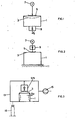
- Fig. 1 shows schematically one principle according to the present invention.
- a container to be leak tested, 1, has an area of its wall 3 which is flexible.
- the principle of the present invention resides in the fact that for leak testing container 1 a biasing member 5 is moved by means of a drive 7 towards and onto the wall of the container 1 and a force detector 9 monitors the reaction force F and generates an electric signal F el according to that force F.
- the force detector 9 is directly coupled to the biasing member 5 and both are driven relative to and onto the flexible area 3 of the wall of the container 1, which latter resides e.g. on a base plate 11.
- the drive 7, which moves one of the biasing member 5, of force detector 9 or of a combined force detector and biasing member 5/9 arrangement with respect to the flexible area 3 of the wall of container 1, is in fact realised as a pneumatic drive.
- Force detector 9 and biasing member 5 are kept stationary in a test chamber 13.
- the test chamber 13 is evacuated, thereby generating a pressure difference ⁇ p between the surrounding of the container 1 and its interior, which is directed from the inside to the outside of the container.
- the flexible wall portion 3 is bent outwards and moved towards and onto the force detector 9, which here and as a preferred embodiment simultaneously acts as biasing member and as force detector.
- biasing container 1 by relatively moving biasing member 5 towards and onto container 1 leads to force detector 9 detecting a rising force F as the container 1 is urged together in the embodiments according to fig. 1 or 2 or is expanded according to the preferred embodiment of fig. 3 .
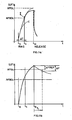
- fig. 4 as soon as biasing member 5 contacts the wall to of container 1, the reaction force F rises as biasing member 5 is further urged onto the wall of container 1. After a predetermined time t 1 the relative movement of container wall 1 and biasing member 5 is stopped. This leads to a constant reaction force F o , if the container is unleaky and its wall does not further react up to achieving equilibrium of shape.
- a large leak LL is inventively already detected if the biasing member is moved at a predetermined rate or speed towards and onto the container wall and after a predetermined time span as of t 1 - to a predetermined force, as of F o , is not reached.
- such a behaviour of the container is already detected after a time span which is shorter than t 1 - to, so as to become able to stop biasing of the container early enough and before pressing or suctioning a product contained in the container to and into its surrounding.
- a shorter time span t LL - to and after this time span of increased biasing it is checked whether a predetermined threshold force, according to fig. 4 as of F LL , is reached or not. If it is not reached according to the biasing course (b) further biasing is stopped and the heavily leaky container is freed of any bias as quickly as possible.
- the reaction force monitored, F will reach after the predetermined time span of increasing biasing, t 1 - to, the threshold value as of F o as required and leakage behaviour of the container will only be detected afterwards.
- a predetermined time span t 2 - t 1 up to t 2 is installed, during which the system consisting of container 1, biasing member 5 and force detector 9 is left for attaining equilibrium e.g. of the shape of the container.
- the monitored reaction force F At or after reaching t 2 the monitored reaction force F, then prevailing, F 2 , is sampled and stored. After lapse of a further time span t 3 - t 2 up to t 3 again the monitored reaction force F is sampled as F 3 and is compared with reaction force F 2 as was stored. Thus, the difference ⁇ F of F 3 and F 2 is principally evaluated as leak indicative signal.
- Combined biasing member and force detector 9/5 is rigidly mounted within chamber 13 and preferably opposite and adjacent to the area 3 of flexible wall of container 1.
- the force detector 9 generates electrical signal S(F) as a function of the force acting between area 3 and contact area of the biasing/force detector assembly 9/5, which is as schematically shown provided with a surface structure 19 to prevent that surface shutting a leak of area 3 incidentally just happening to be located there, where area 3 is or is going to contact the assembly 9/5.
- the same structuring 19a is preferably provided at the bottom surface of chamber 13.
- the signal S(F) is fed at a time t LL , controlled by timing unit 17 as schematically shown and by switch unit SW 1 , to a comparator unit 21, where at time moment t LL the output signal S(F) is compared with the large leak indicative threshold value S 0 (F LL ) as preset at unit 23.
- switching unit SW 2 Whenever at moment t LL , S 0 (F LL ) is not reached by the force signal S(F), switching unit SW 2 , the input thereof being connected to S(F), is opened disabling via a control unit 25 further biasing e.g. by pump 15. If the threshold value S(F LL ) is at least reached by S(F) at the moment t LL , then signal S(F) is led to a further switching unit SW 3 , where, controlled from timing unit 17 at moment t 2 , the prevailing signal is in fact sampled and stored in storing unit 27. Thus, in unit 27 there is stored a value according to force F 2 of fig. 4 .
- the output of the storing unit 27 is fed to a comparing unit 28, to which, again controlled from timing unit 17, at moment t 3 signal S(F) is additionally fed according to the then prevailing value F 3 .
- comparing unit 28 compares the force value at moment t 2 with the value of that force prevailing at moment t 3 .
- the output ⁇ F of comparator unit 28 is indicative of leak behaviour of container 1 under test beside of a large leak prevailing, which has been previously detected.
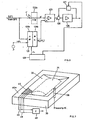
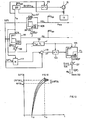
- Fig. 6 a most preferred realisation of storing unit 27 and comparator unit 28, schematically shown in fig. 5 , is depicted.
- the output signal of the force detector 9 in assembly 9/5 is input to a conversion unit 121, which comprises, as an input stage, an analogue to digital converter 121a, followed by a digital to analogue converter 121b.
- the output of the converter stage 121 is fed to a difference amplifier unit 123, which additionally receives directly the output signal from force detector 9.
- the output of the difference amplifier 123 according to the comparator unit 28 of fig. 5 , acts on a further amplifier unit 125, the output of which being superimposed at 128 to its input via storage unit 127.
- the input of the storage unit 127 is fed from the output of unit 125.
- a timer unit 129 controls the arrangement.
- the timer unit 129 For storing the signal according to the force value F 2 as of fig. 5 , at time t 2 the timer unit 129 enables a conversion cycle at unit 121, so that a reconverted analogue output signal el o (F 2 ) appears at the analogue output.
- the substantially same signal S(F) from force detector 9 is applied as a signal el(F 2 ) to the second input of unit 123.
- a zero signal should appear at the output unit 125, which signal is stored in the storing unit 127, enabled by the timing unit 129, according to unit 17 of fig. 5 .
- no conversion is triggered at the unit 121, so that there appears at the input of amplifier 123 directly from force detector 9 the signal according to the force value F 3 prevailing at t 3 , and from stage 121 the stored signal according to force value F 2 , which was prevailing at t 2 .
- the zero offset signal which was stored to unit 127, is now superimposed as an offset compensating signal to the output of unit 123, so that the resulting signal at the output of amplifier unit 125 is zero offset compensated. This allows a very accurate measurement of the force difference ⁇ F as of fig. 4 .
- the volume of the test chamber 13 is not very critical with respect to the volume of the container to be tested.
- a force is evaluated.
- accuracy of measurement is largely dependent on the remaining volume between the wall of the test chamber and that of the container, because leakage will affect the pressure in that intermediate volume the more the smaller than said intermediated volume is selected.
- a wall portion of the container is urged against the force detector. Leakage to the surrounding will affect such force irrespective of the surrounding volume and thus of the relative volume of the test chamber with respect to the container to be tested.
- testing chambers which are minimum in volume with respect to the containers to be tested therein, if biasing is performed by vacuumising according to fig. 3 .
- the level of measuring is set and may be selected.
- the flexible wall portion in its bowing action will reside along a successively larger contact area on the force detector and/or the biasing member with an eye on the embodiment of fig. 3 , establishing a larger biasing pressure difference ⁇ p will lead to an overproportionally rising biasing force F.
- This accords to an amplification of the signal ⁇ F according to fig. 4 to be exploited. This again significantly improves accuracy of the overall measuring system and makes it easy to establish the range of evaluation signals.
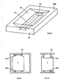
- a recess 32 substantially shaped according to pouch 34 (dashed lines) to be tested therein.
- a suctioning line 36 for instance in the base plate 30 there is applied one or more than one suctioning line 36 to be connected to an evacuating pump according to pump 15.
- the top plate 37 as of fig. 8 which is conceived similarly to the bottom plate 30, has a recess 38, which, once the top plate 37 is deposited upon the base plate 30, defines with recess 32 the test chamber or test cavity.
- the bottom surface 40b and the top surface 40a of the two plates 30 and 37 do snugly and vacuum tightly fit and are thereby, if necessary, provided with respective sealing members all around the recesses 32/38.
- a force detector arrangement 42 with a large detection surface 44 fitted to the shape of the test cavity.
- the force detector arrangement 42 preferably operates on the principle of resistance gauge, i.e. pressurising the surface 44 will generate a force according to pressure multiplied by contact surface, which will slightly bend the resistance gauge element, thereby generating the electric signal S(F) according to fig. 5 .
- force detectors operating on different physical principles may clearly be used, thereby preferably force detectors, which operate on minimum mechanical movement.
- a piezo force detector may be used.
- the test cavity as formed by the two recesses 32 and 38 of fig. 7 and 8 for testing pouches is made to snugly fit the shape of a container 1 (a pouch) to be tested therein, it is possible to get additional information especially about large leaks by measuring the electric impedance outside the container under test, which is changed whenever e.g. a liquid content of a leaky container is urged or suctioned out of such container.
- the inner surface of the test cavity may be subdivided in electrically conductive electrodes 44. Every second electrode 44 is connected to one input connector 46 to an impedance measuring unit 48, every electrode in-between to input connector 49.
- Impedance measuring unit 48 may measure AC and/or DC impedance, preferably DC impedance. Thus, whenever the container, as pouch 34, is biased and a liquid or pasty content is pressed into the test cavity, irrespective of large leak measurement according to figs. 4 and 5 as was discussed above, a change in impedance measured at the unit 48 will indicate such a leak, and the output signal of the impedance measuring unit 48 will stop further biasing of the container.
- lines or pipes may be provided abutting in the test cavity and connected to liquid and/or gaseous cleaning media as to a source of air or, and preferably, nitrogen and/or of pressurised liquid flushing medium and further (not shown) a heater may be incorporated into the walls of the test cavity to dry and additionally clean a spoiled test cavity.
- a container 1 to be tested is biased, be it according to the teaching of the fig. 1 or 2 , to which fig. 10 is directed or according to fig. 3 , to which fig. 9 is directed, at least two wall portions of the container, which are disposed one opposite the other, denoted in the figs. 9 and 10 as 51a and 51b, will be firmly pressed onto the biasing member/force detector arrangement or more generically to surfaces.
- a leak to be in such an area of container's wall such a leak might be clogged by such a surface. Therefore and as schematically shown in figs.
- fig. 11a Force versus time courses as measured according to the inventive method and with an inventive apparatus in preferred mode are shown in fig. 11a for very large and large leaks VGL, in fig. 11b for small leaks and for unleaky containers in fig. 11c . These figs. shall be discussed in connection with fig. 12 , which shows a preferred monitoring and control unit.
- the timing unit 201 of fig. 12 initiates at time t 1o biasing of a container 1 under test, be it according to the embodiment of fig. 1 or 2 or 3 . According to the embodiment of fig. 3 , thus the timing unit 201 initiates evacuation of the test cavity 13.
- comparator unit 102 is enabled by timer unit 201 at t 10 + ⁇ T.
- the VGL signal preferably stops the biasing cycle, because this would lead just to pressing content of the container under test into the surrounding.
- biasing of the container under test continues up to a further moment of time t 13 .
- the timer unit 201 disables biasing drive, be it the mechanical drive 7 according to the embodiments of the figs. 1 and 2 , or the evacuation pump 15 as of the embodiment of fig. 3 .
- timer unit 201 position of timer unit 201 enables comparator unit 111, to which a further reference value RFGL is led, generated by a reference signal source 113. If at time t 13 the force detected by the force detector has not reached RFGL, then comparator unit 111 generates an output signal GL indicating that the container under test has a large leak GL. Here again, some reactions are taken with respect to further operation of the testing system.
- the timer unit 201 is principally reset because the testing has been completed and the quality of the instantaneously tested container 1 established has been identified. This is schematically shown in fig. 12 by the signal RS 201. If not reset shortly after t 13 the value S(F) (t 13 ) of the force detected by the force detector is stored in a holding or storing unit 117. The output of the holding or storing unit 117 is led to one input of the difference forming unit 119, whereas the second input of this unit 119 is connected to the output S(F) of the force detector.
- the reference value ⁇ FREF is fed to the comparator unit 125.
- the value of ⁇ FREF may controllably be varied in time and/or a reference value ⁇ R , to which ⁇ FREF is referred to, may also controllably be varied in time.
- a signal FL is generated at unit 125, indicating presence of a fine leak FL in the container 1 under test. This according to the situation as shown in fig. 11b . If the ⁇ F-signal does not reach ⁇ FREF then the container is considered unleaky, as none of the signals VGL, GL and FL has been generated. This accords with fig. 11c .
- This bypass of a testing chamber 13, whereat a container has been identified as heavily or even slightly leaking, is performed so as not to influence further testing results at that chamber and especially not to spoil the vacuum pump 15 connected thereto due to content of the leaky container being suctioned towards and into such pump.
- This bypass chamber is reconditioned during further testing cycles at the other chambers after the leaky container having been removed.
- Reconditioning may be done by heating that chamber 13, flushing it by a liquid and/or a gas, preferably nitrogen, especially by a heated gas.
- the force values measured at the tight containers are slightly different and define a statistic distribution as shown in fig. 13 .
- the value of RFGL as used at the comparator 111 of fig. 12 or as used according to the figs. 11a to 11c is found in that an offset value ⁇ RFGL is subtracted from (RFGL) m .
- temperatures and manufacturing tolerances of such containers may vary. Such parameters may slowly change and may vary (RFGL) m .
- the actual output signal of the force detector is entered into an averaging unit 130 as shown in fig. 14 , wherein the last m values of actual force of not heavily leaky containers are averaged.
- the output average result signal accords with (RFGL) m of fig. 13 , now varies in time e.g. due to varying manufacturing parameters of one and the same type of containers.
- the result of this operation is a dynamically varying reference value RFGL, which is applied to comparator unit 111 of fig. 12 .
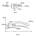
- This dynamically varying reference value RFGL is shown in fig. 15 qualitatively, starting from an initial setting as e.g. found as was explained with the help of measurements at unleaky test containers.
- the average force value S ( F ) (t 13) is now the basis for also referring ⁇ FREF to. Therefore, and as is shown in fig. 12 , the force difference reference value ⁇ FREF is not referred to an absolute static value as ⁇ R , but is referred to S(F) .
- FIG. 17 there is shown an inline plant, wherein generically assembling and testing of containers is done inline.
- pouches are first welded at a welding station 60 in a base plate 30 as shown in fig. 7 used as carrier and support for assembling.
- the carrier formed by plate 30 is moved to an applicator station, where the top plate 37 as of fig. 8 is assembled upon the bottom plate 30.
- the thus sealingly closed test cavity is moved and applied to a test station 64, where the inventive test is performed.
- the system of welder 60 and/or applicator 62 and/or tester 64 may thereby be stationary with respect to a conveyor 66 for base plate 30. Nevertheless, and depending on time requested for a certain operation, especially tester 64 may be moved together with conveyor 66 for a predetermined time, so as to become independent of speed of conveyor 66.
- a leak testing technique which is much less critical in achieving the same accuracy as with leak testing techniques evaluating pressure measurements.
- Biasing containers according to the present invention is much simpler than establishing a perfect vacuum around such container and measuring a biasing force considerably easier than accurately measuring the time development of a vacuum pressure surrounding the container.
- vacuum measurement much more unknown and uncontrollable parameters may affect the measured entities, namely vacuum pressure, than in the here inventively exploited force measurement.
- setting of the measuring level in vacuum measurement technique greatly influences the expenditure for vacuum pumps, varying and setting a biasing force is of much less effort.
- the inventive method and apparatus are especially suited for testing pouches, but clearly may be used for testing all kinds of containers up to big tanks as long as a wall portion thereof is flexibly bendable.
- the present invention may be realised at inline plants with a multitude of testing stations, e.g. arranged on a carousel with a very high throughput.
Landscapes
- Physics & Mathematics (AREA)
- General Physics & Mathematics (AREA)
- Examining Or Testing Airtightness (AREA)
- Closing Of Containers (AREA)
Abstract
Description
- The present invention is directed to a method for leak testing closed containers with at least one flexible wall area and to a leak testing apparatus for leak testing a closed container with such flexible wall area, irrespective whether such container is filled with a product or not.
- When testing closed containers one known technique is to arrange a container to be tested into a test cavity which is then sealingly closed, then to evacuate the interior space of the test cavity around the container to be tested and to evaluate the time behaviour of the pressure in the surrounding of the container after evacuation has been stopped at a predetermined level. Although this technique is of very high accuracy it necessitates utmost care for reaching such high accuracy. The volume of the test cavity and its shape must snugly fit the outside shape of the container to be tested. On one hand minimising this volume leads to respectively short evacuation time, on the other hand the degree of this minimising largely governs the detection accuracy reached. As a change in pressure in the surrounding of the container is detected as leak indication entity, the smaller than the volume is in which, through a leak, pressure is affected, the higher will be the detection accuracy.
- Further, accuracy is largely influenced by the degree of vacuum which is established in the surrounding of the container, which makes it necessary, for high accuracy, to provide relatively expensive vacuum pumps, possibly even multiple stage vacuum pumps, if vacuum is to be established down to the level as only reached with turbo vacuum pumps.
-
US 4 756 184 A discloses a method for leak testing closed containers having a flexible wall area, by applying a biasing member onto said area. - It is an object of the present invention to provide for a method and apparatus as mentioned above, which remedies for the drawbacks of state of the art leak testing technique using pressure monitoring. This object is resolved by the method of leak testing as mentioned above, comprising the steps of relatively moving a biasing member towards and onto the flexible wall area of the container, stopping such moving and monitoring a biasing force on said container. The biasing force monitored is sampled at a first point in time resulting in a first force measuring signal and is sampled at at least one second subsequent point in time, resulting in a second force measuring signal. There is further generated a difference signal in dependency of said two measuring signals as a leak indicative signal.
- Thereby, the present invention departs from the recognition that if a container to be tested is biased, leading to either compression or expansion of such container, biasing forces will apply to surfaces applied externally to the wall of the container as reaction forces of the expanded or the compressed container. Such reaction forces may easily be monitored. If such biasing is installed to a predetermined level and then stopped, a tight container will lead to monitoring a constant reaction force according to the biasing level reached. If the container is leaky, there will occur an exchange of medium between the surrounding of the container and its inside, leading to a decrease of the reaction force monitored over time. Thereby, the accuracy of such a technique is largely independent from the volume surrounding the container under test, and is further primarily given by the degree of biasing and the force detecting surface towards which the biased container reacts.
- In a preferred embodiment of the inventive method, biasing is installed up to a predetermined biasing force.
- Having reached such predetermined biasing force, it is further proposed to wait for a time span before by sampling the respective first and second force measuring signals are generated, in dependency of which the difference signal is generated. Thereby, in this time span the biased container can stabilise its shape. In one operating embodiment biasing of the container under test is controlled as a function of the difference signal generated, so as to hold said difference signal on a predetermined value and exploiting the action of the biasing member as a leak indication. Thereby, a negative feedback loop is established, where the biasing member controllably counteracts a change of force monitored due to leakage, so that in extreme no change of force will occur due to the fact that the biasing member maintains by appropriate action a constant reaction force.
- In a most preferred embodiment biasing the container is not established by relatively moving external surfaces onto the wall of the container, but in that a pressure difference is installed between the inside of the container and its surrounding. Thereby, the pressure difference is in a most preferred embodiment established by evacuating the surrounding of the container. The flexible wall area of the container has then the tendency of bowing outwards, and if this bowing outwards is barred by stationary surfaces outside the container, the container will act with a respective force on such surfaces. This force is monitored.
- So as to avoid that due to the inventively exploited biasing, an existing leak in a container is clogged by the wall area with such leak being urged onto an external surface, it is proposed to provide surface areas contacted by the wall of the container, as it is biased, with a structure. Such a structure may be realised by interposing a mesh- or grid-like member between wall area of the container and such an external surface or, and preferably, by roughening such surface as by etching or machining.
- In a further preferred embodiment the first force measuring signal is stored and the difference signal is generated in dependency of the stored first force measuring signal and the second measuring signal.
- In a further preferred mode of operation, already in the first point in time there is generated the difference signal namely from the first force measuring signal stored, and the first force measuring signal unstored. The resulting difference signal, as a zero offset signal, is stored and zero offset of latter generated difference signal is compensated by the stored zero offset signal.
- So as to early detect large leaks, then smaller leaks, it is further proposed to compare the biasing force monitored with at least one predetermined threshold value, at the latest when sampling at said first point in time, which leads to identifying very large leaks and further preferably to compare the difference signal with at least one predetermined threshold value.
- An object of the present invention is to provide a method for inline assembling and testing of closed containers according to
claim 1. - The invention is especially suited for leak testing so-called pouches, all around flexible wall containers, filled e.g. with pasty material.
- Further preferred forms of realising the inventive method and the inventive apparatus will be become apparent to the skilled artisan reading the following detailed description as well as the claims.
- By way of examples the following figures show:
- Fig. 1
- schematically, a first embodiment of an inventive apparatus operating according to the inventive method, whereat a container under test is biased by compression, biasing member and force detector being arranged on opposite sides of the container;
- Fig. 2
- in a representation according to
fig. 1 , an embodiment whereat the container resides on a support and biasing member as well as force detector are arranged on the opposite side of such support; - Fig. 3
- in a schematic representation according to those of
figs. 1 and 2 , a further and preferred embodiment of the inventive apparatus and method, whereat biasing the container is realised by evacuating the surrounding of the container under test; - Fig. 4
- a qualitative force versus time diagram explaining the inventive method as performed by an inventive apparatus;
- Fig. 5
- by means of a schematic and simplified functional block/signal-flow diagram, an embodiment of the inventive apparatus operating according to the inventive method;
- Fig. 6
- schematically and in a simplified form a preferred realisation of storing and comparing units as preferably used in the inventive apparatus;
- Figs. 7 and 8
- schematically and in a perspective view, a test chamber for realising the invention as shown in
fig. 3 and for testing pouches; - Figs. 9 and 10
- schematically, further preferred features at a test cavity operated according to
fig. 3 ; - Figs 11a to 11c
- force-signal versus time diagrams showing a preferred realisation form of the inventive method by an inventive apparatus;
- Fig. 12
- by means of a signal flow/functional block diagram the embodiment of the inventive apparatus performing measurements as explained with the help of the
figures 11a to 11c ; - Fig. 13
- a force signal versus time diagram showing the statistic distribution of biasing force reached after a predetermined time of biasing at unleaky containers of the same type due e.g. to manufacturing tolerances;
- Fig. 14
- a simplified functional block/signal-flow diagram showing a further preferred feature of the inventive apparatus and method for generating an adaptive threshold value at the embodiment according to
fig. 12 ; - Fig. 15
- over time, qualitatively time courses of adaptively varied threshold values of the inventive apparatus and method as realised by the embodiment of
figs. 14 and16 , where - Fig. 16
- shows an embodiment for adaptively adjusting a further reference or threshold value for the inventive method and as realised at the preferred apparatus, and
- Fig. 17
- schematically shows an inline plant for inline assembling and testing containers.
-
Fig. 1 shows schematically one principle according to the present invention. A container to be leak tested, 1, has an area of itswall 3 which is flexible. The principle of the present invention resides in the fact that for leak testing container 1 a biasingmember 5 is moved by means of a drive 7 towards and onto the wall of thecontainer 1 and aforce detector 9 monitors the reaction force F and generates an electric signal Fel according to that force F. As show infig. 2 in a preferred mode theforce detector 9 is directly coupled to the biasingmember 5 and both are driven relative to and onto theflexible area 3 of the wall of thecontainer 1, which latter resides e.g. on abase plate 11. - In a still further preferred embodiment and as shown in
fig. 3 the drive 7, which moves one of the biasingmember 5, offorce detector 9 or of a combined force detector and biasingmember 5/9 arrangement with respect to theflexible area 3 of the wall ofcontainer 1, is in fact realised as a pneumatic drive.Force detector 9 and biasingmember 5 are kept stationary in atest chamber 13. - By means of an
evacuation pump 15 thetest chamber 13 is evacuated, thereby generating a pressure difference Δp between the surrounding of thecontainer 1 and its interior, which is directed from the inside to the outside of the container. Thereby, theflexible wall portion 3 is bent outwards and moved towards and onto theforce detector 9, which here and as a preferred embodiment simultaneously acts as biasing member and as force detector. As shown in dotted lines, it is also possible to pressurise thecontainer 1 e.g. with asource 16 of pressurised gas, and dependent on the wall structure ofcontainer 1, to havearea 3 bowing outwards. - Irrespective of the technique, which is inventively exploited and with respect to where the biasing
member 5, where theforce detector 9 are arranged and how the drive 7 is realised, as a mechanical drive as shown infig. 1 or 2 or by a pressure difference applied as shown infig. 3 , biasingcontainer 1 by relatively moving biasingmember 5 towards and ontocontainer 1 leads to forcedetector 9 detecting a rising force F as thecontainer 1 is urged together in the embodiments according tofig. 1 or 2 or is expanded according to the preferred embodiment offig. 3 . According tofig. 4 , as soon as biasingmember 5 contacts the wall to ofcontainer 1, the reaction force F rises as biasingmember 5 is further urged onto the wall ofcontainer 1. After a predetermined time t1 the relative movement ofcontainer wall 1 and biasingmember 5 is stopped. This leads to a constant reaction force Fo, if the container is unleaky and its wall does not further react up to achieving equilibrium of shape. - If the container under stress has a large leak LL according to course (b), then the biasing movement of the biasing member will not lead to a reaction force F achieving Fo at all, but after the time span according to t1 - to a considerably smaller force FLL will be measured or monitored by the
force detector 9. - Thus, a large leak LL is inventively already detected if the biasing member is moved at a predetermined rate or speed towards and onto the container wall and after a predetermined time span as of t1 - to a predetermined force, as of Fo, is not reached.
- Preferably such a behaviour of the container is already detected after a time span which is shorter than t1 - to, so as to become able to stop biasing of the container early enough and before pressing or suctioning a product contained in the container to and into its surrounding. Thus, preferably, there is installed a shorter time span tLL - to and after this time span of increased biasing it is checked whether a predetermined threshold force, according to
fig. 4 as of FLL, is reached or not. If it is not reached according to the biasing course (b) further biasing is stopped and the heavily leaky container is freed of any bias as quickly as possible. - If the
container 1 is not heavily leaky, the reaction force monitored, F, will reach after the predetermined time span of increasing biasing, t1 - to, the threshold value as of Fo as required and leakage behaviour of the container will only be detected afterwards. - After having checked for large leaks LL and having disabled further biasing of the container as at time t1, preferably a predetermined time span t2 - t1 up to t2 is installed, during which the system consisting of
container 1, biasingmember 5 and forcedetector 9 is left for attaining equilibrium e.g. of the shape of the container. - Thereby, in a preferred mode, t2 is set on the maximum value according to tmax, thus there is valid t2 = tmax. This is especially done if the container under test does not experience e.g. a volume change under the stress of the bias, which leads to a decrease of reaction force in a transient phase which decrease is not due to leakage.
- At or after reaching t2 the monitored reaction force F, then prevailing, F2, is sampled and stored. After lapse of a further time span t3 - t2 up to t3 again the monitored reaction force F is sampled as F3 and is compared with reaction force F2 as was stored. Thus, the difference ΔF of F3 and F2 is principally evaluated as leak indicative signal.
- As further shown in
fig. 4 it is also possible to sample and store force F2 on the rising slope of biasing thecontainer 1 and to wait the force F monitored to re-reach in the falling slope of F, after having stopped further biasing - t1 - the value according to F2, thereby indicating that the system has in fact stabilised. In this case time moment t2 will be defined by the force F as monitored re-reaching the preset and stored value F2. - In
fig. 5 the inventive apparatus in its principle form which performs the procedure as explained with the help offig. 4 is schematically shown. Thereby, the same reference numbers are used as in the previous figures with respect to features already described. In thetest chamber 13, which is vacuum tight, thecontainer 1 to be tested is deposited. Thevacuum pump 15 is operated controlled by atiming unit 17.Pump 15 evacuateschamber 13 preferably at a constant and adjustable rate. - Combined biasing member and
force detector 9/5 is rigidly mounted withinchamber 13 and preferably opposite and adjacent to thearea 3 of flexible wall ofcontainer 1. Theforce detector 9 generates electrical signal S(F) as a function of the force acting betweenarea 3 and contact area of the biasing/force detector assembly 9/5, which is as schematically shown provided with asurface structure 19 to prevent that surface shutting a leak ofarea 3 incidentally just happening to be located there, wherearea 3 is or is going to contact theassembly 9/5. The same structuring 19a is preferably provided at the bottom surface ofchamber 13. - The signal S(F) is fed at a time tLL, controlled by timing
unit 17 as schematically shown and by switch unit SW1, to a comparator unit 21, where at time moment tLL the output signal S(F) is compared with the large leak indicative threshold value S0(FLL) as preset atunit 23. - Whenever at moment tLL, S0(FLL) is not reached by the force signal S(F), switching unit SW2, the input thereof being connected to S(F), is opened disabling via a
control unit 25 further biasing e.g. bypump 15. If the threshold value S(FLL) is at least reached by S(F) at the moment tLL, then signal S(F) is led to a further switching unit SW3, where, controlled from timingunit 17 at moment t2, the prevailing signal is in fact sampled and stored in storingunit 27. Thus, inunit 27 there is stored a value according to force F2 offig. 4 . The output of the storingunit 27 is fed to a comparingunit 28, to which, again controlled from timingunit 17, at moment t3 signal S(F) is additionally fed according to the then prevailing value F3. Thus, comparingunit 28 compares the force value at moment t2 with the value of that force prevailing at moment t3. The output ΔF ofcomparator unit 28 is indicative of leak behaviour ofcontainer 1 under test beside of a large leak prevailing, which has been previously detected. - Instead of evaluating directly the output signal of
comparator unit 28 it is possible to control biasing as a function of the output signal ofcomparator unit 28. Thereby, a negative feedback control loop is installed (not shown), wherein thecomparator unit 28 compares a rated value according to the stored signal in storingunit 27 with an instantaneously prevailing signal, S(F) and as an adjusting unit in the negative feedback control loop a biasing member is operated to minimize the output signal ofcomparator unit 28. Thereby, the control signal of such biasingmember 15 is exploited as leak indicative signal. - In
Fig. 6 a most preferred realisation of storingunit 27 andcomparator unit 28, schematically shown infig. 5 , is depicted. - The output signal of the
force detector 9 inassembly 9/5 is input to aconversion unit 121, which comprises, as an input stage, an analogue todigital converter 121a, followed by a digital toanalogue converter 121b. The output of theconverter stage 121 is fed to adifference amplifier unit 123, which additionally receives directly the output signal fromforce detector 9. The output of thedifference amplifier 123 according to thecomparator unit 28 offig. 5 , acts on afurther amplifier unit 125, the output of which being superimposed at 128 to its input viastorage unit 127. The input of thestorage unit 127 is fed from the output ofunit 125. Atimer unit 129, astimer unit 17 offig. 5 , controls the arrangement. For storing the signal according to the force value F2 as offig. 5 , at time t2 thetimer unit 129 enables a conversion cycle atunit 121, so that a reconverted analogue output signal elo(F2) appears at the analogue output. - Simultaneously the substantially same signal S(F) from
force detector 9 is applied as a signal el(F2) to the second input ofunit 123. Thus, at theoutput unit 125, a zero signal should appear. Nevertheless, in general a zero offset signal will appear at the output ofunit 125, which signal is stored in thestoring unit 127, enabled by thetiming unit 129, according tounit 17 offig. 5 . At time t3 (fig. 5 ) no conversion is triggered at theunit 121, so that there appears at the input ofamplifier 123 directly fromforce detector 9 the signal according to the force value F3 prevailing at t3, and fromstage 121 the stored signal according to force value F2, which was prevailing at t2. Further, the zero offset signal, which was stored tounit 127, is now superimposed as an offset compensating signal to the output ofunit 123, so that the resulting signal at the output ofamplifier unit 125 is zero offset compensated. This allows a very accurate measurement of the force difference ΔF as offig. 4 . - When looking at either of the
figs. 1, 2 or 3 it becomes clear that even if vacuum is used to bias the container's wall towards and onto the force detector, the volume of thetest chamber 13 is not very critical with respect to the volume of the container to be tested. Whereas in evaluating a pressure as is done in prior art leak testers, here inventively a force is evaluated. When evaluating a pressure as e.g. the pressure prevailing in the surrounding of a container to be tested, then accuracy of measurement is largely dependent on the remaining volume between the wall of the test chamber and that of the container, because leakage will affect the pressure in that intermediate volume the more the smaller than said intermediated volume is selected. According to the present invention by providing biasing a wall portion of the container a wall portion of the container is urged against the force detector. Leakage to the surrounding will affect such force irrespective of the surrounding volume and thus of the relative volume of the test chamber with respect to the container to be tested. - Nevertheless, under the aspect of shortening testing cycles it is recommended to provide testing chambers which are minimum in volume with respect to the containers to be tested therein, if biasing is performed by vacuumising according to
fig. 3 . - By selecting the established biasing according to Fo of
fig. 4 and thereby the force and thus signal S(F), the level of measuring is set and may be selected. As the flexible wall portion in its bowing action will reside along a successively larger contact area on the force detector and/or the biasing member with an eye on the embodiment offig. 3 , establishing a larger biasing pressure difference Δp will lead to an overproportionally rising biasing force F. This accords to an amplification of the signal ΔF according tofig. 4 to be exploited. This again significantly improves accuracy of the overall measuring system and makes it easy to establish the range of evaluation signals. - In a preferred embodiment operating according to
fig. 3 pouches filled with a product are tested. Infig. 7 and8 there is shown, in a simplified representation, two halves of a test chamber or test cavity according tochamber 13 offig. 3 , tailored for testing pouches. - According to
fig. 7 there is provided in a basis 30 arecess 32 substantially shaped according to pouch 34 (dashed lines) to be tested therein. For instance in thebase plate 30 there is applied one or more than one suctioningline 36 to be connected to an evacuating pump according to pump 15. - The
top plate 37 as offig. 8 , which is conceived similarly to thebottom plate 30, has arecess 38, which, once thetop plate 37 is deposited upon thebase plate 30, defines withrecess 32 the test chamber or test cavity. Thebottom surface 40b and thetop surface 40a of the twoplates recesses 32/38. In one (or possibly in both) of theplates force detector arrangement 42 with alarge detection surface 44 fitted to the shape of the test cavity. Theforce detector arrangement 42 preferably operates on the principle of resistance gauge, i.e. pressurising thesurface 44 will generate a force according to pressure multiplied by contact surface, which will slightly bend the resistance gauge element, thereby generating the electric signal S(F) according tofig. 5 . - Nevertheless, other force detectors operating on different physical principles may clearly be used, thereby preferably force detectors, which operate on minimum mechanical movement. Thus, e.g. a piezo force detector may be used.
- Especially when the test cavity as formed by the two
recesses fig. 7 and8 for testing pouches is made to snugly fit the shape of a container 1 (a pouch) to be tested therein, it is possible to get additional information especially about large leaks by measuring the electric impedance outside the container under test, which is changed whenever e.g. a liquid content of a leaky container is urged or suctioned out of such container. As shown only in thebottom plate 30 offig. 7 and not in thetop plate 37 offig. 8 , the inner surface of the test cavity may be subdivided in electricallyconductive electrodes 44. Everysecond electrode 44 is connected to oneinput connector 46 to animpedance measuring unit 48, every electrode in-between to inputconnector 49.Impedance measuring unit 48 may measure AC and/or DC impedance, preferably DC impedance. Thus, whenever the container, aspouch 34, is biased and a liquid or pasty content is pressed into the test cavity, irrespective of large leak measurement according tofigs. 4 and 5 as was discussed above, a change in impedance measured at theunit 48 will indicate such a leak, and the output signal of theimpedance measuring unit 48 will stop further biasing of the container. - For cleaning a test cavity e.g. in case content of a leaky container has been pouring out into the test cavity, further (not shown) lines or pipes may be provided abutting in the test cavity and connected to liquid and/or gaseous cleaning media as to a source of air or, and preferably, nitrogen and/or of pressurised liquid flushing medium and further (not shown) a heater may be incorporated into the walls of the test cavity to dry and additionally clean a spoiled test cavity.
- A most important feature, which is preferably provided irrespective whether the system operates according to
fig. 1 or 2 or according tofig. 3 , shall now be described with the help offig. 9 and 10 . - Whenever a
container 1 to be tested is biased, be it according to the teaching of thefig. 1 or 2 , to whichfig. 10 is directed or according tofig. 3 , to whichfig. 9 is directed, at least two wall portions of the container, which are disposed one opposite the other, denoted in thefigs. 9 and 10 as 51a and 51b, will be firmly pressed onto the biasing member/force detector arrangement or more generically to surfaces. Whenever there happens a leak to be in such an area of container's wall, such a leak might be clogged by such a surface. Therefore and as schematically shown infigs. 9 and 10 there is provided at all surface areas to which, during biasing the container, a wall area thereof is pressed, a surface structure, so that such a surface does only contact the wall of thecontainer 1 at distinct contact areas, leaving substantial parts of such wall portion uncontacted. This may be realised by providing a mesh- or grid-like member between the respective surfaces and wall portions ofcontainer 1 or by roughening such surfaces by machining such as by etching or sand-blasting.Mechanical abutments 53 as schematically shown in thefigs. 9 and 10 , which contact respective distinct areas of container's wall are formed by such microstructuring of the respective surface. With an eye on the embodiment according tofigs. 7 and9 it is therefore recommended to have the surface of therespective plates recesses - Force versus time courses as measured according to the inventive method and with an inventive apparatus in preferred mode are shown in
fig. 11a for very large and large leaks VGL, infig. 11b for small leaks and for unleaky containers infig. 11c . These figs. shall be discussed in connection withfig. 12 , which shows a preferred monitoring and control unit. - According to
fig. 11a thetiming unit 201 offig. 12 initiates at time t1o biasing of acontainer 1 under test, be it according to the embodiment offig. 1 or 2 or 3 . According to the embodiment offig. 3 , thus thetiming unit 201 initiates evacuation of thetest cavity 13. - This is shown in
fig. 12 by the biasing start signal BIST/t10. - After a fixed predetermined amount of time ΔT the output signal of the force detector S(F) becomes compared with a first reference signal preset at a presetting source 107, RFVGL. To this target, comparator unit 102 is enabled by
timer unit 201 at t10 + ΔT. - If after time span ΔT the actual monitored force according to the electric signal S(F) of
fig. 12 has not reached the value of RFVGL according to course I offig. 11a , this means that a very large leak VGL is present. This is detected atcomparator 109 generating the output signal VGL. If according to the characteristics shown in theblock 109 offig. 12 the output signal of this comparator unit enabled at t11 = t10 + ΔT is e.g. still at a high value, indicating presence of a VGL, this is output at the VGL output. If the biasing force F has reached and crossed the reference level RFVGL according to course II offig. 11a the VGL output signal is not generated. - The VGL signal preferably stops the biasing cycle, because this would lead just to pressing content of the container under test into the surrounding.
- As shown by the course II of
fig. 11a as VGL does not occur, biasing of the container under test continues up to a further moment of time t13. At the time t13 thetimer unit 201 disables biasing drive, be it the mechanical drive 7 according to the embodiments of thefigs. 1 and 2 , or theevacuation pump 15 as of the embodiment offig. 3 . - Further, position of
timer unit 201 enablescomparator unit 111, to which a further reference value RFGL is led, generated by areference signal source 113. If at time t13 the force detected by the force detector has not reached RFGL, thencomparator unit 111 generates an output signal GL indicating that the container under test has a large leak GL. Here again, some reactions are taken with respect to further operation of the testing system. - If either of the signals VGL or GL are initiated by the
respective comparators timer unit 201 is principally reset because the testing has been completed and the quality of the instantaneously testedcontainer 1 established has been identified. This is schematically shown infig. 12 by the signal RS201. If not reset shortly after t13 the value S(F) (t13) of the force detected by the force detector is stored in a holding or storingunit 117. The output of the holding or storingunit 117 is led to one input of thedifference forming unit 119, whereas the second input of thisunit 119 is connected to the output S(F) of the force detector. After a presettable test cycle time TT starting at t13 or at the moment of storing data in storingunit 117, as schematically shown byunit 121 offig. 12 the force difference ΔF-signal is fed to afurther comparator unit 125 enabled at the lapse of testing time TT. - By means of a further
reference value source 127 the reference value ΔFREF is fed to thecomparator unit 125. As will be explained later the value of ΔFREF may controllably be varied in time and/or a reference value φR, to which ΔFREF is referred to, may also controllably be varied in time. - If the ΔF-signal at time t13 + TT is larger than the reference value ΔFREF, then a signal FL is generated at
unit 125, indicating presence of a fine leak FL in thecontainer 1 under test. This according to the situation as shown infig. 11b . If the ΔF-signal does not reach ΔFREF then the container is considered unleaky, as none of the signals VGL, GL and FL has been generated. This accords withfig. 11c . - If the VGL signal is generated according to
fig. 12 irrespective of the embodiment according to one of thefigs. 1, 2 and 3 , further biasing is immediately stopped. In the embodiment offig. 3 making use of anevacuation pump 15 as a biasing drive, theevacuation pump 15 is immediately disconnected from therespective testing chamber 13. This because by a very large leak thevacuum pump 15 could become contaminated by leaking content of thecontainer 1. - In a multiple chamber inline testing system making use of the embodiment of
fig. 3 with a multitude of testing chambers occurrence of the signal GL - indicating a large leak - and possibly even the occurrence of the signal FL - indicating for a fine leak - leads preferably to disabling or "bypassing" that chamber from further being supplied with containers to be tested, whereas the other chambers are still operating and performing tests on newly supplied containers. - This bypass of a
testing chamber 13, whereat a container has been identified as heavily or even slightly leaking, is performed so as not to influence further testing results at that chamber and especially not to spoil thevacuum pump 15 connected thereto due to content of the leaky container being suctioned towards and into such pump. This bypass chamber is reconditioned during further testing cycles at the other chambers after the leaky container having been removed. - Reconditioning may be done by heating that
chamber 13, flushing it by a liquid and/or a gas, preferably nitrogen, especially by a heated gas. - When looking to the
figs. 11a and 11b it may be recognised that setting the reference value RFGL and especially setting of the reference force difference value ΔFREF may be very critical and may largely influence accuracy of the system. Thereby, influences as surrounding temperature, tolerances of container manufacturing etc. may influence the prevailing force course and lead to false results if these critical reference levels and especially ΔFREF are set for utmost accuracy. - In
fig. 13 there is qualitatively shown the biasing force course according to the courses offig. 11a to 11b , but measured at containers of the same type which have been proven as unleaky. This may have been done by long-term experiments and/or leak detecting systems, which are standard and of utmost accuracy, but slow and/or very expensive. - At t13 the force values measured at the tight containers are slightly different and define a statistic distribution as shown in
fig. 13 . There results an average value (RFGL)m. The value of RFGL as used at thecomparator 111 offig. 12 or as used according to thefigs. 11a to 11c is found in that an offset value ΔRFGL is subtracted from (RFGL)m. During ongoing operation on large series of equal containers, temperatures and manufacturing tolerances of such containers may vary. Such parameters may slowly change and may vary (RFGL)m. - Every time during multiple successive testing at the respective times t13 up to which the respective container has been identified as not heavily leaky, the actual output signal of the force detector is entered into an
averaging unit 130 as shown infig. 14 , wherein the last m values of actual force of not heavily leaky containers are averaged. The output average result signal accords with (RFGL)m offig. 13 , now varies in time e.g. due to varying manufacturing parameters of one and the same type of containers. To the output average resultS(F) and according tofig. 13 the offset ΔRFGL is subtracted, the result of this operation is a dynamically varying reference value RFGL, which is applied tocomparator unit 111 offig. 12 . This dynamically varying reference value RFGL is shown infig. 15 qualitatively, starting from an initial setting as e.g. found as was explained with the help of measurements at unleaky test containers. - As may clearly be seen from
fig. 15 the average force valueS(F) (t13) is now the basis for also referring ΔFREF to. Therefore, and as is shown infig. 12 , the force difference reference value ΔFREF is not referred to an absolute static value as φR, but is referred toS(F) . - An even further improvement of accuracy is reached, which may be realised separately or additionally to realising a dynamic RFGL and based thereon a dynamic upper limit of ΔFREF. Thereby and according to
fig. 16 at the end of the time span TT the actual force difference ΔF-signal is led to anaveraging unit 135 whenever the output signal FL indicates that the container under test is unleaky. The output signal ofunit 135, which accords to an average force difference signalΔF averaged over the last m test cycles is, offset by an amount ΔΔF, the result thereof being used as time varying AFREF-signal applied atunit 127 offig. 12 . - Looking back on
fig. 15 whereat a constant ΔFREF signal was applied, the technique of averaging ΔF results as schematically shown with the course (ΔFREF)t in a dynamically varying value ΔFREF, varying according to variations of disturbing parameters influencing such force difference. It is clear that provision of a dynamically varying (ΔFREF)t signal according to that representation infig. 15 could be realised without providing a dynamically varying base valueS(F) in referring (ΔFREF)t to a stable constant value φR as shown infig. 12 in dashed representation instead of referring to a dynamically varyingS(F) value. - It is evident that preferably the evaluation of the output signal S(F) of the one or more than one force detectors is performed digitally.
- In
fig. 17 there is shown an inline plant, wherein generically assembling and testing of containers is done inline. As an example pouches are first welded at awelding station 60 in abase plate 30 as shown infig. 7 used as carrier and support for assembling. With the same carrier, namelybase plate 30, after a pouch has been assembled therein by welding, the carrier formed byplate 30 is moved to an applicator station, where thetop plate 37 as offig. 8 is assembled upon thebottom plate 30. Thereafter, the thus sealingly closed test cavity is moved and applied to atest station 64, where the inventive test is performed. The system ofwelder 60 and/orapplicator 62 and/ortester 64 may thereby be stationary with respect to aconveyor 66 forbase plate 30. Nevertheless, and depending on time requested for a certain operation, especiallytester 64 may be moved together withconveyor 66 for a predetermined time, so as to become independent of speed ofconveyor 66. - With the inventive method and apparatus there is provided a leak testing technique which is much less critical in achieving the same accuracy as with leak testing techniques evaluating pressure measurements. Biasing containers according to the present invention is much simpler than establishing a perfect vacuum around such container and measuring a biasing force considerably easier than accurately measuring the time development of a vacuum pressure surrounding the container. In vacuum measurement much more unknown and uncontrollable parameters may affect the measured entities, namely vacuum pressure, than in the here inventively exploited force measurement. Whereas setting of the measuring level in vacuum measurement technique greatly influences the expenditure for vacuum pumps, varying and setting a biasing force is of much less effort.
- The inventive method and apparatus are especially suited for testing pouches, but clearly may be used for testing all kinds of containers up to big tanks as long as a wall portion thereof is flexibly bendable. The present invention may be realised at inline plants with a multitude of testing stations, e.g. arranged on a carousel with a very high throughput.
Claims (22)
- A method for inline assembling and testing of closed containers with at least one flexible wall (3) area, comprising the steps of:- assembling a closed container (1)- testing said container (1) on leakiness by:- moving a biasing member (5) relatively to, towards and onto said wall (3) area;- stopping said moving;- monitoring a biasing force on said container (1);- sampling said biasing force monitored at a first point in time, resulting in a first force measuring signal;- storing a signal dependent on said first force measuring signal, thereby generating a stored signal, characterised by;- forming a first difference signal of said signal dependent on said first force measuring signal and said stored signal substantially when said storing is performed;- sampling said biasing force monitored at at least one second subsequent point in time, resulting in a second force measuring signal;- generating a second difference signal in dependency of said stored signal, said second force measuring signal and said first difference signal as a leak indicative signal.
- The method of claim 1, further comprising the step of biasing said wall (3) area up to a predetermined biasing force.
- The method of claim 2, thereby installing, upon reaching said predetermined biasing force, a time span before performing said sampling.
- The method of claim 1, further comprising the step of controlling said biasing as a function of said difference signal so as to hold said difference signal on a predetermined value and exploiting relative action of said biasing member as a leak indication.
- The method of one of claims 1 to 4, further comprising the step of performing said moving by establishing a pressure difference between the inside of said container and its surrounding.
- The method of claim 5, further comprising the step of establishing said pressure difference by evacuating said surrounding.
- The method of one of claims 1 to 6, further comprising the step of providing surface areas contacted by the wall (3) of said container (1) as it is biased with a structure.
- The method of one of claims 1 to 7, further comprising the step of comparing said biasing force monitored with at least one predetermined threshold value at the latest when sampling at said first point in time.
- The method of one of claims 1 to 8, further comprising the step of comparing said second difference signal with at least one predetermined threshold value.
- The method of one of claims 1 to 9, further comprising the step of storing said first force measuring signal by means of an analogue to digital converter enabled for conversion at said first point in time.
- The method of claim 10, further comprising the step of reconverting the digital output signal of said analogue to digital converter into an analogue signal and generating said difference signals with said reconverted analogue signal.
- The method of one of claims 1 to 11, further comprising the step of performing an impedance measurement at or at least adjacent to the wall (3) of said container (1), preferably a resistance measurement with DC and enabling or disabling further moving of said biasing member (5) towards and onto said wall area by the result of said impedance measurement.
- The method of one of claims 1 to 12, further comprising the step of monitoring said biasing force by means of a resistance gauge.
- The method of one of claims 1 to 13, further comprising the steps of sampling said biasing force monitored at a third point in time, not later than said first point in time, resulting in a third force measuring signal, comparing said third force measuring signal with a presettable threshold signal value and generating a "large leak" indication, if said third force measuring signal does not reach said threshold signal value.
- The method of one of claims 1 to 14, further comprising the step of providing a test cavity for said container (1) and cleaning said test cavity (13) after a container (13) therein has been detected as leaky, said cleaning being performed by flushing with a gas, preferably with nitrogen and/or by flushing with a liquid and/or by heating.
- The method of one of claims 1 to 15, further comprising the step of inline testing a series of said containers in a set of test cavities and further comprising the step of disabling testing in a test cavity for at least one testing cycle if the container previously tested therein has turned out to be leaky to a predetermined amount.
- The method of one of claims 1 to 16, further comprising the steps of- moving said biasing member (5) towards and onto said wall area with a predetermined rate;- identifying for a large leak by monitoring said biasing force after a predetermined time of said moving and by monitoring whether said biasing force monitored has or has not reached a first predetermined threshold value.
- The method of one of claims 1 to 17, further comprising the step of moving said biasing member at a constant rate towards and onto said wall (3) area.
- The method of one of claims 1 to 18, further comprising the steps of averaging said first force measuring signal with first force measuring signals sampled during previous testing of containers and generating said difference in dependency of said averaged first measuring signal.
- The method of claim 19, further comprising the steps of shifting said averaged signal by a predetermined signal amount and generating said difference in dependency of said shifted averaged signal.
- The method of one of claims 1 to 20, further comprising the step of comparing said second difference signal with at least one threshold signal.
- The method of claim 21, further comprising the step of averaging said second difference signal with such difference signals generated during previous testing of containers and controlling said threshold value in dependency of said averaging.
Priority Applications (2)
| Application Number | Priority Date | Filing Date | Title |
|---|---|---|---|
| DK09150253.4T DK2040054T3 (en) | 2000-09-26 | 2000-09-26 | Method and apparatus for leak proofing of closed containers |
| EP09150253.4A EP2040054B1 (en) | 2000-09-26 | 2000-09-26 | Method and apparatus for leak testing closed containers |
Applications Claiming Priority (3)
| Application Number | Priority Date | Filing Date | Title |
|---|---|---|---|
| EP00960280A EP1320738B1 (en) | 2000-09-26 | 2000-09-26 | Method and apparatus for leak testing closed containers |
| PCT/CH2000/000526 WO2000073760A2 (en) | 2000-09-26 | 2000-09-26 | Method and apparatus for leak testing closed containers |
| EP09150253.4A EP2040054B1 (en) | 2000-09-26 | 2000-09-26 | Method and apparatus for leak testing closed containers |
Related Parent Applications (1)
| Application Number | Title | Priority Date | Filing Date |
|---|---|---|---|
| EP00960280A Division EP1320738B1 (en) | 2000-09-26 | 2000-09-26 | Method and apparatus for leak testing closed containers |
Publications (3)
| Publication Number | Publication Date |
|---|---|
| EP2040054A2 EP2040054A2 (en) | 2009-03-25 |
| EP2040054A3 EP2040054A3 (en) | 2009-11-04 |
| EP2040054B1 true EP2040054B1 (en) | 2014-03-19 |
Family
ID=4358139
Family Applications (2)
| Application Number | Title | Priority Date | Filing Date |
|---|---|---|---|
| EP09150253.4A Expired - Lifetime EP2040054B1 (en) | 2000-09-26 | 2000-09-26 | Method and apparatus for leak testing closed containers |
| EP00960280A Expired - Lifetime EP1320738B1 (en) | 2000-09-26 | 2000-09-26 | Method and apparatus for leak testing closed containers |
Family Applications After (1)
| Application Number | Title | Priority Date | Filing Date |
|---|---|---|---|
| EP00960280A Expired - Lifetime EP1320738B1 (en) | 2000-09-26 | 2000-09-26 | Method and apparatus for leak testing closed containers |
Country Status (13)
| Country | Link |
|---|---|
| US (2) | US6439032B1 (en) |
| EP (2) | EP2040054B1 (en) |
| JP (1) | JP4854891B2 (en) |
| CN (1) | CN100342225C (en) |
| AT (1) | ATE426152T1 (en) |
| AU (4) | AU2000272661C1 (en) |
| DE (1) | DE60041835D1 (en) |
| DK (2) | DK1320738T3 (en) |
| ES (2) | ES2459665T3 (en) |
| NO (1) | NO20031242D0 (en) |
| PT (2) | PT1320738E (en) |
| RU (2) | RU2243524C1 (en) |
| WO (1) | WO2000073760A2 (en) |
Families Citing this family (45)
| Publication number | Priority date | Publication date | Assignee | Title |
|---|---|---|---|---|
| US6082184A (en) * | 1997-05-27 | 2000-07-04 | Martin Lehmann | Method for leak testing and leak testing apparatus |
| DK1320738T3 (en) * | 2000-09-26 | 2009-06-15 | Martin Lehmann | Method and apparatus for leakage testing of closed containers |
| US6840087B2 (en) * | 2000-09-26 | 2005-01-11 | Martin Lehmann | Method and apparatus for leak testing closed containers |
| ITBO20010371A1 (en) * | 2001-06-12 | 2002-12-12 | Ima Spa | METHOD FOR VERIFYING THE INTEGRITY OF PACKAGES, IN PARTICULAR SINGLE DOSE, AND STATION THAT IMPLEMENTS THIS METHOD |
| EP1469296A1 (en) * | 2003-04-14 | 2004-10-20 | Lorenzo Campanini | Process and apparatus for checking sealor tightness of a package made of flexible or semirigid material |
| US8602974B2 (en) * | 2003-08-13 | 2013-12-10 | G.I. View Ltd. | Gastrointestinal tool over guiding element |
| EP1515364B1 (en) * | 2003-09-15 | 2016-04-13 | Nuvotronics, LLC | Device package and methods for the fabrication and testing thereof |
| US8419678B2 (en) | 2004-01-09 | 2013-04-16 | G.I. View Ltd. | Pressure-propelled system for body lumen |
| US7947013B2 (en) * | 2004-01-09 | 2011-05-24 | G.I. View Ltd. | Pressure-propelled system for body lumen |
| JP4353860B2 (en) * | 2004-06-24 | 2009-10-28 | 株式会社エヌテック | Container inspection method and apparatus |
| US7862875B2 (en) * | 2004-10-04 | 2011-01-04 | Trico Corporation | Flinger disc |
| CN101541227B (en) * | 2005-02-10 | 2013-06-05 | G.I.视频有限公司 | Advancement techniques for gastrointestinal tool with guiding element |
| US9241614B2 (en) * | 2005-08-01 | 2016-01-26 | G.I. View Ltd. | Tools for use in esophagus |
| US20090182197A1 (en) * | 2005-08-01 | 2009-07-16 | G.I. View Ltd. | Tools for use in small intestine |
| US8430809B2 (en) * | 2005-08-01 | 2013-04-30 | G. I View Ltd. | Capsule for use in small intestine |
| WO2005124308A2 (en) * | 2005-09-09 | 2005-12-29 | Martin Lehmann | Methods for manufacturing unleaky closed containers and leak testing apparatus |
| RU2370743C1 (en) * | 2005-09-09 | 2009-10-20 | Мартин Леманн | Method of making tightly sealed containers and leakage test device |
| US7380440B2 (en) * | 2005-09-09 | 2008-06-03 | Martin Lehmann | Methods for manufacturing unleaky closed containers and leak testing apparatus |
| CN103148986B (en) * | 2005-09-09 | 2016-03-02 | 马丁·莱曼 | Method for manufacturing leak-tight closed container and leak testing apparatus |
| JP2011529369A (en) * | 2008-07-30 | 2011-12-08 | ジー・アイ・ヴュー・リミテッド | System and method for improving operability |
| CA2741206C (en) | 2008-11-03 | 2016-01-12 | G.I. View Ltd | Remote pressure sensing system and method thereof |
| RU2390742C1 (en) * | 2008-11-10 | 2010-05-27 | Российская Федерация, от имени которой выступает Государственная корпорация по атомной энергии "Росатом" | Method of inspecting containers with materials |
| ES2665764T3 (en) * | 2009-11-20 | 2018-04-27 | Packaging Technologies & Inspection Llc | Vacuum state at rest for procedure and tightness test system by means of vacuum reduction measurement |
| EP2773937B1 (en) | 2011-11-01 | 2019-10-16 | Teledyne Instruments, Inc. | Flexible container inspection |
| WO2014089342A1 (en) * | 2012-12-05 | 2014-06-12 | University Of Florida Research Foundation, Inc. | Method and apparatus for testing quality of seal and package integrity |
| US9561323B2 (en) * | 2013-03-14 | 2017-02-07 | Fresenius Medical Care Holdings, Inc. | Medical fluid cassette leak detection methods and devices |
| ITBO20130128A1 (en) * | 2013-03-26 | 2014-09-27 | Bonfiglioli Engineering S P A | METHOD AND APPARATUS FOR SYRINGE BODY VERIFICATION. |
| SG11201507838QA (en) * | 2013-03-27 | 2015-10-29 | Wilco Ag | Method of inline inspecting and/or testing devices and apparatus to perform such method |
| KR102377615B1 (en) * | 2013-12-10 | 2022-03-22 | 아벡, 아이엔씨. | Apparatus and methods of use |
| CN104977142A (en) * | 2014-04-09 | 2015-10-14 | 江苏神通阀门股份有限公司 | Closed valve service life test device |
| CN104111150B (en) * | 2014-06-30 | 2017-10-24 | 苏州大学 | The device for detecting sealability and detection method of a kind of container detection mouth |
| CN105444927A (en) * | 2015-11-25 | 2016-03-30 | 广州坚诺机械设备有限公司 | Rapid nondestructive detection device based on extruded container pressure and method |
| US10067027B2 (en) * | 2016-03-04 | 2018-09-04 | Robert Bosch Gmbh | Test methodology to reduce false rejections and increase number of containers tested for tightness |
| CN106370365B (en) * | 2016-08-16 | 2019-07-02 | 中国科学院化学研究所 | Leak detection method for liquid encapsulation device |
| US10319654B1 (en) | 2017-12-01 | 2019-06-11 | Cubic Corporation | Integrated chip scale packages |
| CN108150629A (en) * | 2017-12-29 | 2018-06-12 | 盛瑞传动股份有限公司 | Converter cover assembly and its airtight measurement technique |
| CN108851162B (en) * | 2018-03-29 | 2021-06-01 | 保定市三川电气有限责任公司 | Control method and system for vacuum moisture regaining of materials and moisture regaining machine |
| EP3809108B1 (en) | 2019-10-17 | 2022-10-05 | Delta Engineering Bvba | Leak tester |
| IT201900021456A1 (en) | 2019-11-18 | 2021-05-18 | Ceccarani Eng S R L | DEVICE TO CHECK THE SEALING OF CLOSED FLEXIBLE CONTAINERS |
| DE102019135223A1 (en) * | 2019-12-19 | 2021-06-24 | Krones Ag | Method and device for recognizing the structural integrity of a container to be closed |
| US11867591B2 (en) | 2020-11-12 | 2024-01-09 | Lockheed Martin Corporation | Backup oxygen supply bottle pressure measurement and leak test tool |
| US11692672B2 (en) | 2020-12-17 | 2023-07-04 | Lockheed Martin Corporation | Pressure relief shipping adapter for a bottle head assembly |
| US20250129894A1 (en) * | 2023-10-18 | 2025-04-24 | Lockheed Martin Corporation | Pressure relief shipping adapter |
| IT202300026271A1 (en) * | 2023-12-07 | 2025-06-07 | S A T S R L | PROCEDURE AND APPARATUS FOR CHECKING THE PRESENCE OF ONE OR MORE HOLES IN AN ARTICLE FOR THE CONTAINMENT OF A BIOLOGICAL OR PHARMACEUTICAL MATERIAL |
| WO2026027219A1 (en) | 2024-07-27 | 2026-02-05 | Fresenius Kabi Deutschland Gmbh | Method for testing the leak-tightness of flexible containers and system for testing the leak-tightness |
Family Cites Families (35)
| Publication number | Priority date | Publication date | Assignee | Title |
|---|---|---|---|---|
| US2784373A (en) * | 1953-03-02 | 1957-03-05 | Nat Res Corp | High-vacuum device |
| US3837215A (en) * | 1973-05-21 | 1974-09-24 | T Massage | Method and apparatus for testing sealed containers |
| US4107997A (en) * | 1975-09-15 | 1978-08-22 | Advanced Patent Technology, Incorporated | Alloy sensor |
| FR2351400A1 (en) * | 1976-05-10 | 1977-12-09 | Lesieur Cotelle | Sealed package testing appts. - applies vacuum to chamber around package and monitors package distortion with piezoelectric strain gauges |
| GB2059381A (en) * | 1979-10-06 | 1981-04-23 | Danepak Ltd | Leak detecting of vacuum sealed packages |
| JPS5719638A (en) * | 1980-07-11 | 1982-02-01 | Citizen Watch Co Ltd | Inspection for air leak of wrist watch |
| US4449396A (en) * | 1982-03-01 | 1984-05-22 | Carrier Corporation | Probe for measuring electrical conductance |
| US4459843A (en) * | 1982-07-06 | 1984-07-17 | Durham La Moyne W | Apparatus and method for testing containers |
| JPS59157537A (en) * | 1983-02-28 | 1984-09-06 | Toyo Seikan Kaisha Ltd | Detector for pressure in can |
| US4955226A (en) * | 1984-12-26 | 1990-09-11 | Frito-Lay, Inc. | Method and apparatus for automatically detecting the presence of holes in filled and sealed packed plastic bags |
| GB8506443D0 (en) * | 1985-03-13 | 1985-04-17 | Bishopbarn Ltd | Testing leaks in packages |
| US4715215A (en) * | 1985-04-25 | 1987-12-29 | The Aro Corporation | Method and apparatus for testing the fluid-tight sealed integrity of a hermetically-sealed package in a rapidly-stabilized environment |
| US4771630A (en) * | 1985-12-20 | 1988-09-20 | Warner-Lambert Company | Method and apparatus for testing hermetic seal integrity of sealed packages and containers |
| US4756184A (en) * | 1987-03-12 | 1988-07-12 | General Mills, Inc. | Apparatus and method for seal testing flexible containers |
| DE3716095C1 (en) * | 1987-05-14 | 1988-09-08 | Hamba Maschf | Cup filler for food and beverages, especially for dairy products |
| US4862732A (en) | 1987-10-19 | 1989-09-05 | Benthos, Inc. | Leak testing |
| US4747299A (en) * | 1987-10-28 | 1988-05-31 | The Aro Corporation | Method of testing a package seal |
| SU1619085A1 (en) * | 1988-02-04 | 1991-01-07 | Предприятие П/Я М-5068 | Method of checking air-tightness of articles |
| JPH0257533A (en) * | 1988-08-22 | 1990-02-27 | Taiyo Fishery Co Ltd | Leakage inspecting method for sealed container |
| US5029463A (en) * | 1990-03-01 | 1991-07-09 | American Air Liquide | Leak detection device for in-line measurement of package integrity |
| US5195360A (en) * | 1990-10-12 | 1993-03-23 | General Mills, Inc. | Apparatus and methods for testing double packages |
| GB9204137D0 (en) * | 1992-02-26 | 1992-04-08 | Fenlon Christopher | Sealed package integrity testing machine |
| CH685887A5 (en) * | 1992-08-12 | 1995-10-31 | Martin Lehmann | Container leakage testing device |
| US5915270A (en) | 1992-08-27 | 1999-06-22 | Lehmann; Martin | Method for testing containers, use of the method, and a testing device |
| US5528925A (en) * | 1993-01-19 | 1996-06-25 | Luigino's, Inc. | Method and apparatus for testing the seal between a container and a flexible lid |
| US5533385A (en) * | 1995-02-06 | 1996-07-09 | Frievalt; William | Package seal integrity testing device and method of operation thereof |
| US6202476B1 (en) * | 1995-08-25 | 2001-03-20 | Testamatic Limited | Method of and apparatus for testing for leaks in a package |
| GB9601014D0 (en) | 1996-01-18 | 1996-03-20 | Testamatic Ltd | Package tester |
| US5767392A (en) * | 1996-08-28 | 1998-06-16 | The Clorox Company | Method and apparatus for leak testing containers having a flexible side wall structure |
| EP0791814A3 (en) * | 1997-05-26 | 1997-11-26 | Martin Lehmann | Method for leak testing and leak testing apparatus |
| US6082184A (en) * | 1997-05-27 | 2000-07-04 | Martin Lehmann | Method for leak testing and leak testing apparatus |
| EP0786655B1 (en) * | 1997-05-07 | 2002-07-24 | Martin Lehmann | Procedure for leak testing of closed containers, test chamber, device and installation therefor |
| JP2000088694A (en) * | 1998-09-16 | 2000-03-31 | Ishida Co Ltd | Sealing container tightness inspection device |
| JP2000131182A (en) * | 1998-10-22 | 2000-05-12 | Nikka Kensa Kikai Kk | Method and apparatus for inspection of airtightness defect of airtight container |
| DK1320738T3 (en) * | 2000-09-26 | 2009-06-15 | Martin Lehmann | Method and apparatus for leakage testing of closed containers |
-
2000
- 2000-09-26 DK DK00960280T patent/DK1320738T3/en active
- 2000-09-26 RU RU2003112218/28A patent/RU2243524C1/en not_active IP Right Cessation
- 2000-09-26 AT AT00960280T patent/ATE426152T1/en active
- 2000-09-26 DK DK09150253.4T patent/DK2040054T3/en active
- 2000-09-26 DE DE60041835T patent/DE60041835D1/en not_active Expired - Lifetime
- 2000-09-26 CN CNB008199108A patent/CN100342225C/en not_active Expired - Fee Related
- 2000-09-26 WO PCT/CH2000/000526 patent/WO2000073760A2/en not_active Ceased
- 2000-09-26 PT PT00960280T patent/PT1320738E/en unknown
- 2000-09-26 ES ES09150253.4T patent/ES2459665T3/en not_active Expired - Lifetime
- 2000-09-26 EP EP09150253.4A patent/EP2040054B1/en not_active Expired - Lifetime
- 2000-09-26 EP EP00960280A patent/EP1320738B1/en not_active Expired - Lifetime
- 2000-09-26 ES ES00960280T patent/ES2323749T3/en not_active Expired - Lifetime
- 2000-09-26 US US09/669,669 patent/US6439032B1/en not_active Expired - Lifetime
- 2000-09-26 PT PT91502534T patent/PT2040054E/en unknown
- 2000-09-26 JP JP2001500835A patent/JP4854891B2/en not_active Expired - Lifetime
- 2000-09-26 AU AU2000272661A patent/AU2000272661C1/en not_active Ceased
- 2000-09-26 AU AU7266100A patent/AU7266100A/en active Pending
-
2002
- 2002-07-30 US US10/207,148 patent/US6557395B2/en not_active Expired - Lifetime
-
2003
- 2003-03-18 NO NO20031242A patent/NO20031242D0/en not_active Application Discontinuation
-
2005
- 2005-11-04 AU AU2005229712A patent/AU2005229712C1/en not_active Ceased
-
2008
- 2008-08-11 AU AU2008203815A patent/AU2008203815B9/en not_active Ceased
- 2008-08-14 RU RU2008133456/28A patent/RU2389006C1/en not_active IP Right Cessation
Also Published As
Similar Documents
| Publication | Publication Date | Title |
|---|---|---|
| EP1320738B1 (en) | Method and apparatus for leak testing closed containers | |
| AU2000272661A1 (en) | Method and apparatus for leak testing closed containers | |
| US7313944B2 (en) | Method and apparatus for leak testing closed containers | |
| KR100649266B1 (en) | Apparatus for manufacturing unleaky containers | |
| US7584650B2 (en) | Methods for manufacturing unleaky closed containers and leak testing apparatus | |
| RU2492440C2 (en) | Method of leakage testing of closed container, method of producing hermetically sealed containers and device for leakage testing | |
| CN101126673A (en) | Method and apparatus for leak testing closed containers | |
| RU2344396C2 (en) | Method of checking air-tightness of closed containers and device to this end | |
| CN101126672A (en) | Method and apparatus for leak testing closed containers | |
| CN101126670A (en) | Method and apparatus for leak testing closed containers | |
| CN101126671A (en) | Method and apparatus for leak testing closed containers | |
| KR20080045274A (en) | Method for manufacturing non-sealed airtight container and leak tester | |
| NZ566115A (en) | Methods for manufacturing unleaky closed containers and leak testing apparatus |
Legal Events
| Date | Code | Title | Description |
|---|---|---|---|
| PUAI | Public reference made under article 153(3) epc to a published international application that has entered the european phase |
Free format text: ORIGINAL CODE: 0009012 |
|
| AC | Divisional application: reference to earlier application |
Ref document number: 1320738 Country of ref document: EP Kind code of ref document: P |
|
| AK | Designated contracting states |
Kind code of ref document: A2 Designated state(s): AT BE CH CY DE DK ES FI FR GB GR IE IT LI LU MC NL PT SE |
|
| AX | Request for extension of the european patent |
Extension state: AL LT LV MK RO SI |
|
| PUAL | Search report despatched |
Free format text: ORIGINAL CODE: 0009013 |
|
| AK | Designated contracting states |
Kind code of ref document: A3 Designated state(s): AT BE CH CY DE DK ES FI FR GB GR IE IT LI LU MC NL PT SE |
|
| AX | Request for extension of the european patent |
Extension state: AL LT LV MK RO SI |
|
| 17P | Request for examination filed |
Effective date: 20100209 |
|
| 17Q | First examination report despatched |
Effective date: 20100310 |
|
| AKX | Designation fees paid |
Designated state(s): AT BE CH CY DE DK ES FI FR GB GR IE IT LI LU MC NL PT SE |
|
| 17Q | First examination report despatched |
Effective date: 20110830 |
|
| GRAP | Despatch of communication of intention to grant a patent |
Free format text: ORIGINAL CODE: EPIDOSNIGR1 |
|
| RAP1 | Party data changed (applicant data changed or rights of an application transferred) |
Owner name: WILCO AG |
|
| RIN1 | Information on inventor provided before grant (corrected) |
Inventor name: LEHMANN, MARTIN |
|
| GRAP | Despatch of communication of intention to grant a patent |
Free format text: ORIGINAL CODE: EPIDOSNIGR1 |
|
| INTG | Intention to grant announced |
Effective date: 20140108 |
|
| RIC1 | Information provided on ipc code assigned before grant |
Ipc: G01M 3/36 20060101AFI20131217BHEP |
|
| GRAS | Grant fee paid |
Free format text: ORIGINAL CODE: EPIDOSNIGR3 |
|
| GRAA | (expected) grant |
Free format text: ORIGINAL CODE: 0009210 |
|
| AC | Divisional application: reference to earlier application |
Ref document number: 1320738 Country of ref document: EP Kind code of ref document: P |
|
| AK | Designated contracting states |
Kind code of ref document: B1 Designated state(s): AT BE CH CY DE DK ES FI FR GB GR IE IT LI LU MC NL PT SE |
|
| REG | Reference to a national code |
Ref country code: GB Ref legal event code: FG4D |
|
| REG | Reference to a national code |
Ref country code: CH Ref legal event code: EP |
|
| REG | Reference to a national code |
Ref country code: IE Ref legal event code: FG4D |
|
| REG | Reference to a national code |
Ref country code: AT Ref legal event code: REF Ref document number: 657974 Country of ref document: AT Kind code of ref document: T Effective date: 20140415 |
|
| REG | Reference to a national code |
Ref country code: DE Ref legal event code: R096 Ref document number: 60048489 Country of ref document: DE Effective date: 20140424 |
|
| REG | Reference to a national code |
Ref country code: PT Ref legal event code: SC4A Free format text: AVAILABILITY OF NATIONAL TRANSLATION Effective date: 20140416 |
|
| REG | Reference to a national code |
Ref country code: NL Ref legal event code: T3 |
|
| REG | Reference to a national code |
Ref country code: ES Ref legal event code: FG2A Ref document number: 2459665 Country of ref document: ES Kind code of ref document: T3 Effective date: 20140512 |
|
| REG | Reference to a national code |
Ref country code: SE Ref legal event code: TRGR |
|
| REG | Reference to a national code |
Ref country code: CH Ref legal event code: NV Representative=s name: TROESCH SCHEIDEGGER WERNER AG, CH |
|
| REG | Reference to a national code |
Ref country code: DK Ref legal event code: T3 Effective date: 20140603 |
|
| PG25 | Lapsed in a contracting state [announced via postgrant information from national office to epo] |
Ref country code: FI Free format text: LAPSE BECAUSE OF FAILURE TO SUBMIT A TRANSLATION OF THE DESCRIPTION OR TO PAY THE FEE WITHIN THE PRESCRIBED TIME-LIMIT Effective date: 20140319 Ref country code: CY Free format text: LAPSE BECAUSE OF FAILURE TO SUBMIT A TRANSLATION OF THE DESCRIPTION OR TO PAY THE FEE WITHIN THE PRESCRIBED TIME-LIMIT Effective date: 20140319 |
|
| REG | Reference to a national code |
Ref country code: DE Ref legal event code: R097 Ref document number: 60048489 Country of ref document: DE |
|
| PLBE | No opposition filed within time limit |
Free format text: ORIGINAL CODE: 0009261 |
|
| STAA | Information on the status of an ep patent application or granted ep patent |
Free format text: STATUS: NO OPPOSITION FILED WITHIN TIME LIMIT |
|
| 26N | No opposition filed |
Effective date: 20141222 |
|
| REG | Reference to a national code |
Ref country code: DE Ref legal event code: R097 Ref document number: 60048489 Country of ref document: DE Effective date: 20141222 |
|
| PG25 | Lapsed in a contracting state [announced via postgrant information from national office to epo] |
Ref country code: LU Free format text: LAPSE BECAUSE OF FAILURE TO SUBMIT A TRANSLATION OF THE DESCRIPTION OR TO PAY THE FEE WITHIN THE PRESCRIBED TIME-LIMIT Effective date: 20140926 Ref country code: MC Free format text: LAPSE BECAUSE OF FAILURE TO SUBMIT A TRANSLATION OF THE DESCRIPTION OR TO PAY THE FEE WITHIN THE PRESCRIBED TIME-LIMIT Effective date: 20140319 |
|
| REG | Reference to a national code |
Ref country code: FR Ref legal event code: PLFP Year of fee payment: 16 |
|
| PGFP | Annual fee paid to national office [announced via postgrant information from national office to epo] |
Ref country code: ES Payment date: 20150810 Year of fee payment: 16 Ref country code: CH Payment date: 20150924 Year of fee payment: 16 Ref country code: GB Payment date: 20150923 Year of fee payment: 16 Ref country code: IE Payment date: 20150909 Year of fee payment: 16 Ref country code: PT Payment date: 20150922 Year of fee payment: 16 |
|
| PGFP | Annual fee paid to national office [announced via postgrant information from national office to epo] |
Ref country code: FR Payment date: 20150811 Year of fee payment: 16 Ref country code: AT Payment date: 20150825 Year of fee payment: 16 Ref country code: SE Payment date: 20150911 Year of fee payment: 16 Ref country code: BE Payment date: 20150911 Year of fee payment: 16 |
|
| PGFP | Annual fee paid to national office [announced via postgrant information from national office to epo] |
Ref country code: DK Payment date: 20150910 Year of fee payment: 16 |
|
| PGFP | Annual fee paid to national office [announced via postgrant information from national office to epo] |
Ref country code: IT Payment date: 20150925 Year of fee payment: 16 |
|
| PGFP | Annual fee paid to national office [announced via postgrant information from national office to epo] |
Ref country code: NL Payment date: 20150909 Year of fee payment: 16 |
|
| PG25 | Lapsed in a contracting state [announced via postgrant information from national office to epo] |
Ref country code: GR Free format text: LAPSE BECAUSE OF FAILURE TO SUBMIT A TRANSLATION OF THE DESCRIPTION OR TO PAY THE FEE WITHIN THE PRESCRIBED TIME-LIMIT Effective date: 20140620 |
|
| PG25 | Lapsed in a contracting state [announced via postgrant information from national office to epo] |
Ref country code: BE Free format text: LAPSE BECAUSE OF NON-PAYMENT OF DUE FEES Effective date: 20160930 |
|
| REG | Reference to a national code |
Ref country code: DK Ref legal event code: EBP Effective date: 20160930 |
|
| PG25 | Lapsed in a contracting state [announced via postgrant information from national office to epo] |
Ref country code: SE Free format text: LAPSE BECAUSE OF NON-PAYMENT OF DUE FEES Effective date: 20160927 |
|
| REG | Reference to a national code |
Ref country code: CH Ref legal event code: PL |
|
| REG | Reference to a national code |
Ref country code: SE Ref legal event code: EUG |
|
| REG | Reference to a national code |
Ref country code: NL Ref legal event code: MM Effective date: 20161001 |
|
| REG | Reference to a national code |
Ref country code: AT Ref legal event code: MM01 Ref document number: 657974 Country of ref document: AT Kind code of ref document: T Effective date: 20160926 |
|
| GBPC | Gb: european patent ceased through non-payment of renewal fee |
Effective date: 20160926 |
|
| PG25 | Lapsed in a contracting state [announced via postgrant information from national office to epo] |
Ref country code: PT Free format text: LAPSE BECAUSE OF NON-PAYMENT OF DUE FEES Effective date: 20170327 |
|
| REG | Reference to a national code |
Ref country code: IE Ref legal event code: MM4A |
|
| PG25 | Lapsed in a contracting state [announced via postgrant information from national office to epo] |
Ref country code: NL Free format text: LAPSE BECAUSE OF NON-PAYMENT OF DUE FEES Effective date: 20161001 |
|
| REG | Reference to a national code |
Ref country code: FR Ref legal event code: ST Effective date: 20170531 |
|
| PG25 | Lapsed in a contracting state [announced via postgrant information from national office to epo] |
Ref country code: LI Free format text: LAPSE BECAUSE OF NON-PAYMENT OF DUE FEES Effective date: 20160930 Ref country code: GB Free format text: LAPSE BECAUSE OF NON-PAYMENT OF DUE FEES Effective date: 20160926 Ref country code: FR Free format text: LAPSE BECAUSE OF NON-PAYMENT OF DUE FEES Effective date: 20160930 Ref country code: CH Free format text: LAPSE BECAUSE OF NON-PAYMENT OF DUE FEES Effective date: 20160930 Ref country code: IE Free format text: LAPSE BECAUSE OF NON-PAYMENT OF DUE FEES Effective date: 20160926 |
|
| PG25 | Lapsed in a contracting state [announced via postgrant information from national office to epo] |
Ref country code: AT Free format text: LAPSE BECAUSE OF NON-PAYMENT OF DUE FEES Effective date: 20160926 Ref country code: IT Free format text: LAPSE BECAUSE OF NON-PAYMENT OF DUE FEES Effective date: 20160926 |
|
| REG | Reference to a national code |
Ref country code: BE Ref legal event code: MM Effective date: 20160930 |
|
| PG25 | Lapsed in a contracting state [announced via postgrant information from national office to epo] |
Ref country code: DK Free format text: LAPSE BECAUSE OF NON-PAYMENT OF DUE FEES Effective date: 20160930 |
|
| PG25 | Lapsed in a contracting state [announced via postgrant information from national office to epo] |
Ref country code: ES Free format text: LAPSE BECAUSE OF NON-PAYMENT OF DUE FEES Effective date: 20160927 |
|
| REG | Reference to a national code |
Ref country code: ES Ref legal event code: FD2A Effective date: 20181120 |
|
| PGFP | Annual fee paid to national office [announced via postgrant information from national office to epo] |
Ref country code: DE Payment date: 20190910 Year of fee payment: 20 |
|
| REG | Reference to a national code |
Ref country code: DE Ref legal event code: R071 Ref document number: 60048489 Country of ref document: DE |