RU2492440C2 - Method of leakage testing of closed container, method of producing hermetically sealed containers and device for leakage testing - Google Patents
Method of leakage testing of closed container, method of producing hermetically sealed containers and device for leakage testing Download PDFInfo
- Publication number
- RU2492440C2 RU2492440C2 RU2009124045/28A RU2009124045A RU2492440C2 RU 2492440 C2 RU2492440 C2 RU 2492440C2 RU 2009124045/28 A RU2009124045/28 A RU 2009124045/28A RU 2009124045 A RU2009124045 A RU 2009124045A RU 2492440 C2 RU2492440 C2 RU 2492440C2
- Authority
- RU
- Russia
- Prior art keywords
- specified
- signal
- force
- container
- flexible
- Prior art date
Links
- 238000012360 testing method Methods 0.000 title claims abstract description 31
- 238000000034 method Methods 0.000 title claims abstract description 28
- 238000007789 sealing Methods 0.000 claims description 22
- 238000004519 manufacturing process Methods 0.000 claims description 21
- 238000012935 Averaging Methods 0.000 claims description 10
- 238000005452 bending Methods 0.000 claims description 6
- 238000005259 measurement Methods 0.000 claims description 6
- 238000010998 test method Methods 0.000 claims description 5
- 238000005070 sampling Methods 0.000 claims description 3
- 230000000694 effects Effects 0.000 abstract description 3
- 239000000126 substance Substances 0.000 abstract 1
- 238000006073 displacement reaction Methods 0.000 description 17
- 230000000875 corresponding effect Effects 0.000 description 10
- IQVNEKKDSLOHHK-FNCQTZNRSA-N (E,E)-hydramethylnon Chemical compound N1CC(C)(C)CNC1=NN=C(/C=C/C=1C=CC(=CC=1)C(F)(F)F)\C=C\C1=CC=C(C(F)(F)F)C=C1 IQVNEKKDSLOHHK-FNCQTZNRSA-N 0.000 description 4
- 238000010586 diagram Methods 0.000 description 3
- 239000011888 foil Substances 0.000 description 3
- 101100083446 Danio rerio plekhh1 gene Proteins 0.000 description 2
- 238000000418 atomic force spectrum Methods 0.000 description 2
- 238000006243 chemical reaction Methods 0.000 description 2
- 230000006835 compression Effects 0.000 description 2
- 238000007906 compression Methods 0.000 description 2
- 230000002596 correlated effect Effects 0.000 description 2
- 230000001133 acceleration Effects 0.000 description 1
- 229910052782 aluminium Inorganic materials 0.000 description 1
- XAGFODPZIPBFFR-UHFFFAOYSA-N aluminium Chemical compound [Al] XAGFODPZIPBFFR-UHFFFAOYSA-N 0.000 description 1
- 230000006399 behavior Effects 0.000 description 1
- 238000012937 correction Methods 0.000 description 1
- 230000001419 dependent effect Effects 0.000 description 1
- 238000013461 design Methods 0.000 description 1
- 238000001514 detection method Methods 0.000 description 1
- 238000009826 distribution Methods 0.000 description 1
- 238000005516 engineering process Methods 0.000 description 1
- 230000007613 environmental effect Effects 0.000 description 1
- 238000002474 experimental method Methods 0.000 description 1
- 230000003993 interaction Effects 0.000 description 1
- 230000007774 longterm Effects 0.000 description 1
- 229910052751 metal Inorganic materials 0.000 description 1
- 239000002184 metal Substances 0.000 description 1
- 238000012544 monitoring process Methods 0.000 description 1
- 238000003825 pressing Methods 0.000 description 1
- 238000003672 processing method Methods 0.000 description 1
- 238000007788 roughening Methods 0.000 description 1
- 230000003068 static effect Effects 0.000 description 1
- 238000003466 welding Methods 0.000 description 1
Images


Classifications
-
- G—PHYSICS
- G01—MEASURING; TESTING
- G01M—TESTING STATIC OR DYNAMIC BALANCE OF MACHINES OR STRUCTURES; TESTING OF STRUCTURES OR APPARATUS, NOT OTHERWISE PROVIDED FOR
- G01M3/00—Investigating fluid-tightness of structures
- G01M3/02—Investigating fluid-tightness of structures by using fluid or vacuum
- G01M3/36—Investigating fluid-tightness of structures by using fluid or vacuum by detecting change in dimensions of the structure being tested
-
- G—PHYSICS
- G01—MEASURING; TESTING
- G01M—TESTING STATIC OR DYNAMIC BALANCE OF MACHINES OR STRUCTURES; TESTING OF STRUCTURES OR APPARATUS, NOT OTHERWISE PROVIDED FOR
- G01M3/00—Investigating fluid-tightness of structures
- G01M3/02—Investigating fluid-tightness of structures by using fluid or vacuum
- G01M3/26—Investigating fluid-tightness of structures by using fluid or vacuum by measuring rate of loss or gain of fluid, e.g. by pressure-responsive devices, by flow detectors
Landscapes
- Physics & Mathematics (AREA)
- General Physics & Mathematics (AREA)
- Examining Or Testing Airtightness (AREA)
Abstract
Description
Настоящее изобретение отходит от технологии изготовления герметичных контейнеров, раскрытой в документе WO 00/073760 или патентах США 6557395, 6439032 или 6840087, (все принадлежат заявителю настоящего изобретения).The present invention departs from the manufacturing technology of sealed containers disclosed in document WO 00/073760 or US patents 6557395, 6439032 or 6840087 (all belong to the applicant of the present invention).
Таким образом, для изготовления герметичных контейнеров, которые имеют первую гибкую зону стенки и вторую гибкую зону стенки с разными характеристиками гибкости, настоящее изобретение представляет собой способ изготовления, в котором, после выполнения закрытого контейнера, по меньшей мере один смещающий элемент перемещают к одной из первой и второй гибких зон стенки контейнера и на нее. Подобное вызывающее смещение перемещение прекращают. Осуществляют отслеживание смещающей силы, действующей на контейнер, и осуществляют выборку значения отслеживаемой смещающей силы, что в результате дает первый измерительный сигнал силы в первый момент времени. Осуществляют дополнительную выборку значения указанной отслеживаемой смещающей силы по меньшей мере в один второй последующий момент времени, что в результате дает второй измерительный сигнал силы. Разностный сигнал формируется в зависимости от первого и второго измерительных сигналов силы. Указанный контейнер считают герметичным, если разностный сигнал удовлетворяет критерию для испытания. Тем самым, смещающий элемент перемещают к первой гибкой зоне стенки и на первую гибкую зону стенки контейнера, и отслеживание смещающей силы осуществляют у второй гибкой зоны. Выборка значения отслеживаемой смещающей силы, которая в результате дает указанный первый измерительный сигнал силы, включает в себя определение максимальной величины сигнала, характеризующего силу, которая имела место в течение промежутка времени, прошедшего до первого момента времени и включающего в себя первый момент времени.Thus, for the manufacture of airtight containers that have a first flexible wall zone and a second flexible wall zone with different flexibility characteristics, the present invention is a manufacturing method in which, after the container is closed, at least one biasing element is moved to one of the first and second flexible zones of the container wall and onto it. Such displacement causing displacement is stopped. The biasing force acting on the container is monitored and the value of the monitored biasing force is sampled, which results in the first measuring force signal at the first moment in time. An additional sampling of the value of the indicated monitored bias force is carried out at least at one second subsequent moment in time, which results in a second force measuring signal. The difference signal is formed depending on the first and second measuring force signals. The specified container is considered leakproof if the differential signal meets the criteria for testing. Thereby, the biasing element is moved to the first flexible zone of the wall and to the first flexible zone of the container wall, and the biasing force is monitored at the second flexible zone. A sample of the value of the monitored bias force, which as a result gives the specified first measuring signal of the force, includes determining the maximum value of the signal characterizing the force that took place during the period of time that has passed before the first time and includes the first time.
В одном варианте осуществления указанного способа, смещающий элемент перемещают до заданного положения относительно контейнера, которое в одном варианте осуществления определяется механическим упором. Кроме того, в одном варианте осуществления, прекращение перемещения смещающего элемента выполняют по меньшей мере по существу в первый момент времени, таким образом, по меньшей мере по существу в тот момент, в который выборка значения отслеживаемой смещающей силы приводит к первому измерительному сигналу силы.In one embodiment of the method, the biasing element is moved to a predetermined position relative to the container, which in one embodiment is determined by a mechanical stop. In addition, in one embodiment, stopping the movement of the biasing element is performed at least essentially at the first time moment, thus at least essentially at that moment at which the selection of the value of the monitored biasing force leads to the first force measuring signal.
В одном варианте осуществления, выбирают заданный промежуток времени и определяют максимальную величину силы, которая имела место в течение данного заданного промежутка времени, прошедшего до первого момента времени и включающего в себя первый момент времени.In one embodiment, a predetermined period of time is selected and the maximum amount of force that has occurred during a given predetermined period of time elapsed before the first point in time and including the first point in time is determined.
В одном варианте осуществления смещение включает в себя перемещение по меньшей мере двух смещающих элементов к первой гибкой зоне стенки и на первую гибкую зону стенки с противоположных сторон контейнера.In one embodiment, the offset includes moving at least two biasing elements toward the first flexible zone of the wall and the first flexible zone of the wall from opposite sides of the container.
В одном варианте осуществления первая гибкая зона стенки контейнера представляет собой зону стенки корпуса контейнера, и вторая гибкая зона стенки представляет собой герметизирующий элемент, закрывающий отверстие корпуса контейнера.In one embodiment, the first flexible zone of the container wall is the wall zone of the container body, and the second flexible zone of the wall is a sealing element covering the opening of the container body.
Тем самым, в одном варианте осуществления вторая гибкая зона представляет собой подобный фольге герметизирующий элемент, закрывающий указанное отверстие.Thus, in one embodiment, the second flexible zone is a foil-like sealing element covering said hole.
В дополнительном варианте осуществления отслеживание смещающей силы у второй гибкой зоны стенки выполняют вдоль поверхности измерения силы, которая расположена на расстоянии заданной величины от второй гибкой зоны, при этом указанная вторая гибкая зона стенки рассматривается при несмещенном состоянии контейнера. Данная заданная величина существенно меньше максимального расстояния, на которое вторая гибкая зона стенки может в общей сложности выгибаться наружу вследствие повышенного давления в закрытом контейнере.In an additional embodiment, tracking the bias force at the second flexible zone of the wall is performed along the surface of the force measurement, which is located at a distance of a predetermined value from the second flexible zone, while the specified second flexible zone of the wall is considered when the container is not biased. This predetermined value is significantly less than the maximum distance by which the second flexible zone of the wall can, in total, bend outward due to increased pressure in the closed container.
В одном варианте осуществления, отслеживание смещающей силы включает в себя отслеживание посредством тензорезистора.In one embodiment, tracking biasing force includes tracking by a strain gauge.
В дополнительном варианте осуществления указанного способа, отслеживаемую смещающую силу сравнивают в третий момент времени, предшествующий указанному первому моменту времени, с пороговой величиной, и определяют контейнер как имеющий большую утечку, если отслеживаемая сила не достигает по меньшей мере пороговой величины.In an additional embodiment of the method, the monitored biasing force is compared at a third point in time preceding the indicated first moment of time with a threshold value, and the container is identified as having a large leak if the monitored force does not reach at least a threshold value.
В дополнительном варианте осуществления способа изготовления выполняют множество контейнеров, перемещающихся на конвейере, и выполняют перемещение смещающих элементов, прекращение перемещения, отслеживание смещающей силы, осуществляют указанную выборку значения, формируют разностный сигнал и дополнительно выполняют указанную оценку негерметичности/герметичности на более чем одном из перемещаемых контейнеров на конвейере, по меньшей мере в основном одновременно.In an additional embodiment of the manufacturing method, a plurality of containers are carried out moving on a conveyor, and displacement elements are displaced, displacement is stopped, displacement force is monitored, the indicated value is sampled, a difference signal is generated, and additionally, said leakage / tightness assessment is performed on more than one of the transported containers on the conveyor, at least basically simultaneously.
В дополнительном варианте осуществления, отслеживаемую силу сравнивают в третий момент времени, предшествующий первому моменту времени, с пороговой величиной, и контейнер оценивают как не имеющий большой утечки, если отслеживаемая сила в третий момент времени по меньшей мере достигает пороговой величины. Отслеживаемую величину силы в указанный третий момент времени, если пороговая величина по меньшей мере достигнута, усредняют вместе с подобными значениями силы, созданными у ранее подвергнутых испытанию контейнеров, которые были оценены как не имеющие большой утечки, и пороговую величину используют в зависимости от результата подобного усреднения.In a further embodiment, the monitored force is compared at a third point in time preceding the first moment of time with a threshold value, and the container is judged to have no large leakage if the monitored force at least reaches a threshold value at the third point in time. The tracked force value at the indicated third point in time, if the threshold value is at least reached, is averaged together with similar force values created for previously tested containers that were evaluated as not having large leakage, and the threshold value is used depending on the result of such averaging .
В дополнительном варианте осуществления разностный сигнал сравнивают с указывающей на малую утечку пороговой величиной.In a further embodiment, the difference signal is compared with a threshold indicating a small leak.
Еще в одном дополнительном варианте осуществления, разностный сигнал усредняют вместе с такими разностными сигналами, которые были сформированы во время предшествующего испытания контейнеров, которые были определены как герметичные, при этом указывающую на малую утечку пороговую величину регулируют в зависимости от результата подобного усреднения.In yet a further embodiment, the difference signal is averaged together with such difference signals that were generated during the previous test of the containers, which were determined to be sealed, while the threshold value indicating a small leak is adjusted depending on the result of such averaging.
В еще одном дополнительном варианте осуществления предусмотрена по меньшей мере одна пороговая величина силы, и отслеживаемую силу сравнивают с подобной пороговой величиной, в результате чего указанную пороговую величину корректируют в зависимости от результата сравнения.In yet a further embodiment, at least one force threshold value is provided, and the monitored force is compared with a similar threshold value, as a result of which the threshold value is adjusted depending on the comparison result.
Различные варианты осуществления, определенные выше с их определенными признаками, могут быть объединены, в результате чего будут определены дополнительные варианты осуществления способа изготовления закрытых герметичных контейнеров с соответствующим образом скомбинированными признаками.The various embodiments defined above with their specific features can be combined, as a result of which further embodiments of the method for manufacturing closed sealed containers with suitably combined features will be determined.
Устройство для испытаний на герметичность в соответствии с настоящим изобретением, предназначенное для испытаний на герметичность закрытого контейнера с по меньшей мере первой и второй гибкими зонами стенки, имеющими разные характеристики гибкости, содержит смещающее устройство для сжатия контейнера, подвергаемого испытанию. Оно дополнительно содержит датчик силы, который размещается на стенке контейнера, подвергаемого испытанию, и который генерирует электрический выходной сигнал. Выход указанного датчика силы функционально соединен с блоком памяти, выход которого функционально соединен с одним входом блока сравнения, при этом второй вход блока сравнения функционально соединен с выходом датчика силы. Смещающее устройство расположено так, чтобы обеспечить смещение первой гибкой зоны контейнера, а датчик силы расположен с возможностью его взаимодействия со второй гибкой зоной контейнера.The leakproofness testing apparatus in accordance with the present invention, designed for leakproofness testing of a closed container with at least first and second flexible wall zones having different flexibility characteristics, comprises a biasing device for compressing the container to be tested. It further comprises a force sensor which is located on the wall of the container to be tested and which generates an electrical output signal. The output of the indicated force sensor is functionally connected to the memory unit, the output of which is functionally connected to one input of the comparison unit, while the second input of the comparison unit is functionally connected to the output of the force sensor. The biasing device is positioned to provide displacement of the first flexible zone of the container, and the force sensor is located with the possibility of its interaction with the second flexible zone of the container.
В одном варианте осуществления устройства, смещающее устройство содержит по меньшей мере два, выполненных с возможностью перемещения друг относительно друга, смещающих элемента, перемещаемых друг относительно друга в плоскости. Тем самым, датчик силы имеет поверхность измерения силы, которая обеспечивает определение сил, по существу перпендикулярных к указанной плоскости.In one embodiment of the device, the biasing device comprises at least two displaceable elements displaceable relative to each other in the plane. Thereby, the force sensor has a force measuring surface that provides a determination of forces substantially perpendicular to said plane.
В дополнительном варианте осуществления устройства датчик силы содержит тензорезистор.In a further embodiment of the device, the force sensor comprises a strain gauge.
В еще одном дополнительном варианте осуществления смещающее устройство взаимодействует с механическим упором, ограничивающим его смещающее воздействие на контейнер.In yet another additional embodiment, the biasing device interacts with a mechanical stop, limiting its biasing effect on the container.
В еще одном дополнительном варианте осуществления устройства, выход датчика силы функционально соединен с входом блока определения максимальной величины.In yet a further embodiment of the device, the output of the force sensor is operatively connected to the input of the maximum value determining unit.
В еще одном дополнительном варианте осуществления устройства в соответствии с настоящим изобретением, оно содержит конвейерное устройство для множества указанных контейнеров. Предусмотрены по меньшей мере два указанных смещающих устройства и датчика силы, перемещающихся вместе с конвейером.In yet a further embodiment of the device in accordance with the present invention, it comprises a conveyor device for a plurality of said containers. At least two of these biasing devices and force sensors are provided that move with the conveyor.
Таким образом, различные варианты осуществления устройства могут быть объединены, что приводит к дополнительным вариантам осуществления подобного устройства с комбинированными признаками.Thus, various embodiments of the device can be combined, which leads to additional embodiments of such a device with combined features.
Дополнительно разработан способ изготовления герметично закрытых контейнеров с первой и второй гибкими зонами стенки, имеющими разные характеристики гибкости, в котором выполняют закрытый контейнер, и по меньшей мере один смещающий элемент перемещают относительно одной из гибких зон контейнера, к ней и на нее. Указанное перемещение прекращают. Осуществляют отслеживание смещающей силы, действующей на указанный контейнер. Осуществляют выборку значения отслеживаемой смещающей силы, что в результате дает первый измерительный сигнал силы в первый момент времени. Осуществляют выборку значения отслеживаемой смещающей силы по меньшей мере в один второй последующий момент времени, что в результате дает второй измерительный сигнал силы. Разностный сигнал формируют на основе первого и второго измерительных сигналов силы как один указывающий на утечку сигнал. Средний сигнал из разностных сигналов, сформированных во время предшествующего испытания контейнеров, корректируют в соответствии с текущим разностным сигналом, если контейнер, фактически подвергаемый испытанию, является герметичным. Тем самым, разностный сигнал сравнивают по меньшей мере с одним пороговым сигналом, при этом указанный пороговый сигнал регулируют в зависимости от указанного среднего сигнала. Затем выполняют перемещение смещающего элемента относительно первой гибкой зоны стенки, к ней и на нее, и осуществляют отслеживание смещающей силы на второй гибкой зоне стенки. Выборка значения смещающей силы, которая в результате дает первый измерительный сигнал силы, включает в себя определение максимальной величины сигнала силы, которая имела место в течение промежутка времени, прошедшего до первого момента времени и включающего в себя первый момент времени.Additionally, a method has been developed for manufacturing hermetically sealed containers with first and second flexible wall zones having different flexibility characteristics in which a closed container is made, and at least one biasing element is moved relative to one of the flexible zones of the container, to and onto it. The indicated movement is stopped. Track the biasing force acting on the specified container. The value of the monitored biasing force is sampled, which results in the first force measuring signal at the first instant of time. The value of the monitored biasing force is sampled at least at one second subsequent point in time, which results in a second force measuring signal. The difference signal is formed on the basis of the first and second measuring force signals as one signal indicating a leak. The average signal from the difference signals generated during the previous test of the containers is adjusted in accordance with the current difference signal if the container actually being tested is leakproof. Thus, the difference signal is compared with at least one threshold signal, wherein said threshold signal is adjusted depending on said average signal. Then, the biasing element is moved relative to the first flexible zone of the wall, to it and onto it, and the biasing force is monitored on the second flexible zone of the wall. The selection of the bias force value, which as a result gives the first measuring signal of the force, includes determining the maximum value of the force signal that took place during the period of time that has elapsed before the first time and includes the first time.
В соответствии с еще одним дополнительным вариантом осуществления, разработан способ изготовления герметично закрытых контейнеров с первой и со второй гибкими зонами стенки, имеющими разные характеристики гибкости. Тем самым, выполняют закрытый контейнер и по меньшей мере один смещающий элемент перемещают относительно одной из указанных гибких зон стенки контейнера, к ней и на нее. Перемещение прекращают. Осуществляют отслеживание смещающей силы, действующей на контейнер. Осуществляют выборку значения отслеживаемой смещающей силы, что в результате дает первый измерительный сигнал силы в первый момент времени. Дополнительно осуществляют выборку значения отслеживаемой смещающей силы по меньшей мере в один второй последующий момент времени, что в результате дает второй измерительный сигнал силы. Разностный сигнал формируют на основе первого и второго измерительных сигналов силы, в качестве одного, указывающего на утечку сигнала. Осуществляют дополнительную выборку значения отслеживаемой смещающей силы в дополнительный момент времени, что в результате дает фактический дополнительный измерительный сигнал силы, который указывает на утечку. Средний сигнал из дополнительных измерительных сигналов силы формируют во время предшествующего испытания герметичных контейнеров, и подобный усредненный сигнал корректируют в соответствии с фактическим дополнительным измерительным сигналом силы, если фактический дополнительный измерительный сигнал силы указывает на герметичный контейнер. Тем самым, разностный сигнал сравнивают с пороговой величиной, которая зависит от указанного усредненного сигнала. Контейнер, который определен как негерметичный, отбраковывают.In accordance with yet another additional embodiment, a method has been developed for manufacturing hermetically sealed containers with first and second flexible wall zones having different flexibility characteristics. Thereby, a closed container is made and at least one biasing element is moved relative to one of said flexible zones of the container wall, to and onto it. Moving stop. Track the biasing force acting on the container. The value of the monitored biasing force is sampled, which results in the first force measuring signal at the first instant of time. Additionally, the value of the monitored biasing force is sampled at at least one second subsequent point in time, which results in a second force measuring signal. A difference signal is generated based on the first and second measuring force signals, as one indicating a signal leak. An additional sample of the value of the monitored biasing force is carried out at an additional point in time, which results in the actual additional measuring force signal, which indicates a leak. The average signal from the additional force measuring signals is generated during the previous test of the sealed containers, and a similar averaged signal is corrected in accordance with the actual additional force measuring signal if the actual additional force measuring signal indicates a sealed container. Thus, the difference signal is compared with a threshold value, which depends on the specified averaged signal. A container that is defined as leaky is discarded.
Тем самым, перемещение смещающего элемента выполняют относительно первой гибкой зоны стенки, к ней и на нее, и выполняют отслеживание смещающей силы на второй гибкой зоне. Выборка значения отслеживаемой смещающей силы, которая в результате дает первый измерительный сигнал силы, включает в себя определение максимальной величины сигнала силы, которая имела место в течение промежутка времени, прошедшего до первого момента времени и включающего в себя первый момент времени.Thereby, the movement of the biasing element is performed relative to the first flexible zone of the wall, to it and onto it, and tracking of the biasing force on the second flexible zone is performed. A sample of the value of the monitored biasing force, which as a result gives the first measuring signal of the force, includes determining the maximum value of the signal of force, which took place during the period of time elapsed before the first time and including the first time.
В соответствии с еще одним дополнительным вариантом осуществления, разработан способ изготовления закрытых контейнеров с гибкой частью стенки, в котором выполняют закрытый контейнер и подвергают его смещающему воздействию. Отслеживают смещающую силу, действующую на контейнер, и, исходя из подобной отслеживаемой силы, определяют максимальную величину силы, которая имела место в течение некоторого промежутка времени. Сигнал, который зависит от указанной определенной максимальной величины силы, запоминают и сравнивают с сигналом, зависящим от отслеживаемой смещающей силы. Контейнер отбраковывают как негерметичный в зависимости от результата указанного сравнения.In accordance with another additional embodiment, a method for manufacturing closed containers with a flexible part of the wall is developed, in which a closed container is made and subjected to biasing. The biasing force acting on the container is monitored and, based on such a monitored force, the maximum value of the force that has occurred over a period of time is determined. The signal, which depends on the specified certain maximum magnitude of the force, is stored and compared with a signal that depends on the monitored biasing force. The container is rejected as leaky depending on the result of the specified comparison.
Изобретение далее будет дополнительно проиллюстрировано на примерах с помощью фигур. Данные фигуры показывают:The invention will be further illustrated by way of example using the figures. These figures show:
фиг.1 - в схематическом и упрощенном виде закрытый контейнер, подвергаемый испытанию на герметичность в рамках изготовления подобных контейнеров, являющихся герметичными, в соответствии с настоящим изобретением;figure 1 is a schematic and simplified view of a closed container subjected to a leak test in the manufacture of such containers, which are airtight, in accordance with the present invention;
фиг.2 - увеличенную зону изображения в соответствии с фиг.1, при этом показана смещающая сила, отслеживаемая у одной из гибких зон стенки контейнера согласно фиг.1;figure 2 is an enlarged area of the image in accordance with figure 1, while showing a biasing force, tracked at one of the flexible zones of the container wall according to figure 1;
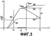
фиг.3 - качественные различные характеристики изменения силы в зависимости от времени, для контейнеров, подвергаемых испытанию с помощью устройства в соответствии с настоящим изобретением и посредством методики испытаний в рамках способа изготовления в соответствии с настоящим изобретением;figure 3 - qualitative various characteristics of the change of force with time, for containers being tested using the device in accordance with the present invention and by means of testing methods in the manufacturing method in accordance with the present invention;
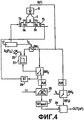
фиг.4 - упрощенную, показывающую поток сигналов/функциональную блок-схему устройства в соответствии с настоящим изобретением, работающего в соответствии с методикой испытания на герметичность в рамках способа изготовления в соответствии с настоящим изобретением;figure 4 is a simplified, showing the signal flow / functional block diagram of a device in accordance with the present invention, operating in accordance with the leak test method within the manufacturing method in accordance with the present invention;
фиг.5 - вариант осуществления, предназначенный для точного выполнения сравнения цифровых сигналов, применимого в устройстве в соответствии с фиг.4;5 is an embodiment designed to accurately perform a comparison of digital signals applicable in the device in accordance with figure 4;
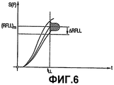
фиг.6 - разные траектории кривых, зависящих от силы сигналов с течением времени, имеющие место для одинаковых контейнеров с одинаковой степенью герметичности и обусловленные, например, производственными допусками или изменяющимися параметрами окружающей среды;6 - different trajectories of curves depending on the strength of the signals over time, occurring for the same containers with the same degree of tightness and due, for example, manufacturing tolerances or changing environmental parameters;
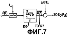
фиг.7 - вариант осуществления, предназначенный для генерирования изменяющейся во времени пороговой величины для обнаружения больших утечек;Fig. 7 is an embodiment for generating a time-varying threshold for detecting large leaks;
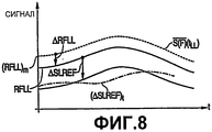
фиг.8 - качественные траектории кривых изменения времени и сигналов пороговой величины, используемых в некоторых вариантах осуществления настоящего изобретения;FIG. 8 illustrates qualitative trajectories of time curves and threshold signals used in some embodiments of the present invention; FIG.
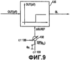
фиг.9 - оценку, посредством упрощенной функциональной блок-схемы и, исходя из указывающего на утечку сигнала, того, имеет ли подвергаемый испытанию контейнер малую утечку или нет;FIG. 9 is an assessment, by means of a simplified functional block diagram, and based on a signal indicating a leak, whether the container under test has a small leak or not;
фиг.10 - генерирование для одного варианта осуществления настоящего изобретения, изменяющейся во времени пороговой величины для индикации малой утечки;figure 10 - generating for one variant of implementation of the present invention, a time-varying threshold for indicating low leakage;
фиг.11 - на упрощенном и схематическом изображении встроенное в поточную линию устройство для испытаний на герметичность в соответствии с настоящим изобретением, предназначенное для высокоскоростного испытания контейнеров, применяемого в рамках способа изготовления в соответствии с настоящим изобретением, при этом данное устройство в конечном счете обеспечивает выбор только герметичных контейнеров из потока закрытых контейнеров.11 is a simplified and schematic representation of an in-line leak test device in accordance with the present invention for high-speed container testing used in the manufacturing method in accordance with the present invention, and this device ultimately provides a choice only sealed containers from a stream of closed containers.
Фиг.1 схематически показывает принцип, лежащий в основе настоящего изобретения. Закрытый контейнер 1, подлежащий испытанию на герметичность, например, в производственной поточной линии для окончательного изготовления исключительно герметичных контейнеров, имеет первую зону 3а его общей стенки 3, которая является гибкой. Отверстие 4 контейнера 1 герметично закрыто герметизирующим, подобным фольге элементом, который представляет собой вторую гибкую зону 3b стенки 3 контейнера. Зоны 3а и 3b имеют разные характеристики гибкости. Примером и наиболее распространенным вариантом контейнера 1 является бутылка, при этом стенка 3с бутылки выполнена из пластика, и отверстие в стенке герметично закрыто подобным фольге закрывающим элементом 4, который герметично присоединен к границе отверстия 4 стенки 3с бутылки, например, посредством сварки. Подобный фольге закрывающий элемент, с одной стороны, указан как гибкий, но он является по существу не эластичным, поскольку он изготовлен из фольги из металлизированного пластика или из пластифицированной металлической фольги, подобной фольге из алюминия. В противоположность данной второй гибкой зоне 3b, образованной указанным, герметизирующим подобным фольге, закрывающим элементом, первая гибкая зона 3а стенки 3с бутылки выполнена из более толстого пластика и является более эластичной. Таким образом, указанные первая и вторая зоны 3а, 3b всей стенки 3 контейнера имеют разные характеристики гибкости.Figure 1 schematically shows the principle underlying the present invention. The
Для проведения испытания на герметичность, контейнер 1 размещают между двумя смещающими элементами 5а и 5b смещающего устройства 5. Смещающие элементы 5а и 5b перемещают друг относительно друга по направлению друг к другу и друг от друга для создания смещающей нагрузки В, действующей на первую гибкую зону 3а. Тем самым, в варианте осуществления, подобном показанному на фиг.1, оба элемента 5а и 5b перемещают одинаковым образом по направлению друг к другу и друг от друга и относительно механической базы 6 машины, например, конвейера для контейнера 1. Посредством перемещения элементов 5а, 5b по направлению друг к другу, контейнер 1 сдавливают в зоне 3а с тем, чтобы он выгибался внутрь, как показано пунктирной линией. Вследствие повышенного давления внутри контейнера 1, вызванного указанным смещением, приводящим к сдавливанию, посредством смещающего устройства 5 вторая гибкая зона 3b, образованная герметизирующим подобным фольге элементом, выгибается наружу, как также показано на фиг.1 и на увеличенном изображении на фиг.2. Таким образом, выгибающаяся наружу, вторая гибкая зона 3b прижимается к поверхности 9а измерения, имеющейся на датчике 9 силы, который неподвижен по отношению к механической базе 6 установки для испытаний. Расстояние d между второй гибкой частью 3b стенки, образованной герметизирующим подобным фольге элементом, и поверхностью 9а измерения, имеющейся на датчике 9 измерения, выбирают таким, чтобы оно было значительно меньше максимального расстояния D, на которое подобный фольге элемент может выгибаться наружу вследствие повышенного давления внутри контейнера 1; в этой связи фиг.2 не показывает правильного соотношения величин d и D. Для круглой зоны 3b с радиусом в диапазоне 1 или 2 см, расстояние d выбрано таким, что оно составляет, например, 0,5 мм. Эффект от выбора малого расстояния d таков, что выгибание второй гибкой зоны 3b наружу ограничено такой величиной, что на соединение для запечатывания или сварной шов 5 по существу не действует механическая нагрузка, обусловленная сопротивлением растяжению, вызванным выгибанием наружу.To conduct a leak test, the
Как дополнительно схематически показано на фиг.1, соответствующие приводы 7а и 7b вызывают перемещение смещающих элементов 5а и 5b друг относительно друга для сдавливания первой гибкой зоны 3а, и указанное перемещение ограничено соответствующими упорами 8а и 8b.As further schematically shown in FIG. 1, the
На фиг.3 показан график зависимости силы от времени, разъясняющий способ по изобретению, реализуемый устройством согласно изобретению. В нулевые (0) моменты времени в соответствии с фиг.3 начинается приводящее к смещению перемещение двух смещающих элементов 5а и 5b. Поскольку характеристика движения, то есть ускорение и, следовательно, скорость, сообщаемые приводами 7а и 7b смещающим элементам 5а и 5b, известна, промежуток времени, необходимый для перемещения смещающих элементов 5а и 5b до упоров 8а и 8b согласно фиг.1, известен и показан на фиг.3 посредством промежутка времени t1. Когда смещающие элементы 5а и 5b войдут в контакт с первой гибкой зоной 3а, то при сдавливающем смещении данной зоны 3а давление внутри контейнера 1 повышается независимо от того, заполнен ли контейнер продуктом или нет, при этом повышение давления приводит к тому, что вторая гибкая зона 3b, образованная герметизирующим подобным фольге элементом, выгибается наружу. Как только зазор, обусловленный расстоянием d, будет перекрыт выгибающейся второй гибкой зоной 3b, и вследствие продолжающегося перемещения элементов 5а и 5b, вызывающего увеличение смещения, а также вследствие увеличивающейся поверхности контакта между поверхностью выгибающейся наружу второй зоны 3b и поверхностью 9а измерения, имеющейся на датчике 9 измерения, сила F, измеряемая посредством данного неподвижного датчика 9 силы, увеличивается. Осуществляют отслеживание по меньшей мере части хода изменения силы со временем F(t) до момента времени t1. Посредством отслеживания максимальной величины, определяется максимальная величина силы, отслеживание которой осуществляется датчиком 9 силы до момента времени t1. Таким образом, в одном варианте осуществления, как показано на фиг.3, посредством траектории кривой (а1), характеристику перемещения, обусловленную приводами 7а и 7b, и место размещения упоров 8а и 8b выбирают такими, что траектория кривой силы F(t), отслеживание которой осуществляется датчиком 9 силы, достигнет максимальной величины в пределах промежутка времени до момента t1. Тем не менее, на фиг.3 три реальных типа траекторий кривых силы F(t) показаны исключительно количественно в виде (а1), (а2) и (а3). Если траектория кривой по существу соответствует (а1), это определяется, таким образом, за счет определения максимальной величины Fmax1 в течение промежутка времени до t1. С данной траекторией кривой (а1) сталкиваются, если контейнер является негерметичным, но не имеет большой утечки, как будет указано ниже. Траектории кривых F(t), соответствующие (а2) или (а3), указывают на то, что контейнер или является герметичным, или имеет малую утечку. Если траектория кривой соответствует (а2), максимальная величина силы, определенная до момента t1, соответствует Fmax1. Если траектория кривой F(t) соответствует (а3), то максимальная величина силы, определенная до момента времени t1, составляет Fmax3.Figure 3 shows a graph of the dependence of force on time, explaining the method according to the invention, implemented by the device according to the invention. At zero (0) times in accordance with FIG. 3, displacement-causing movement of two biasing
Независимо от того, когда максимальная величина Fmax силы имеет место в момент времени t1, в течение промежутка времени от 0 до t1, данная максимальная величина будет выявлена.Regardless of when the maximum magnitude F max of the force takes place at time t 1 , over a period of time from 0 to t 1 , this maximum value will be detected.
Если контейнер 1, подвергаемый испытанию, имеет большую утечку LL, то траектория кривой F(t) будет такой, как качественно показано посредством траектории кривой (b) на фиг.3. Для предотвращения дальнейшего, обусловленного смещением, сдавливания контейнера 1 с большой утечкой посредством смещающих элементов 5а и 5b, устанавливают по меньшей мере один дополнительный заданный момент времени tLL или промежуток времени, начинающийся в нулевой момент времени, и в данной момент времени tLL осуществляется отслеживание того, достигла ли изменяющаяся сила F(t), действующая на контейнер, подвергаемый испытанию, по меньшей мере заданной величины FLL силы. Если будет определено, что в момент времени tLL пороговая величина FLL силы не будет достигнута, как показано посредством траектории кривой (b) на фиг.3, то дополнительное сдавливание, обусловленное смещением элементов 5а и 5b, будет прекращено до достижения соответствующих им упоров 8а и 8b, с тем, чтобы предотвратить выдавливание содержимого контейнера 1 посредством большой течи. Если контейнер 1, подвергаемый испытанию, не имеет большой течи LL, то максимальная величина Fmax силы будет определена в пределах промежутка времени до момента t1, независимо от того, в какой момент времени подобная максимальная величина будет иметь место, и независимо от ее абсолютной величины. Таким образом, разные контейнеры без большой утечки могут дать максимальные значения Fmax силы с различными абсолютными величинами, и подобные максимальные значения могут иметь место в течение промежутка времени, проходящего до момента t1, в разные моменты времени.If the
Что касается определения или выявления максимального значения Fmax силы из зависимости силы от времени F(t) для контейнера, подвергаемого испытанию, то разные возможности известны квалифицированному специалисту в данной области техники. Одна прямая возможность, которая позволяет учитывать траектории кривых такого типа, как соответствующие (а2) и (а3), заключается в осуществлении выборки значения и запоминания значений изменяющейся силы F(t) и, после достижения момента t1, выбора наибольшего значения силы, которое было занесено в память. Это легко выполняется посредством аналого-цифрового преобразования электрического выходного сигнала датчика 9 силы и запоминания фактической траектории кривой зависимости силы от времени посредством цифровых дискретизированных замеров. Кроме того, для квалифицированного специалиста в данной области техники совершенно очевидно, что, если придерживаться данной методики, заносится в память только та часть траектории кривой F(t) во времени, в которой ожидается наличие максимальной величины Fmax силы. Данная зона траектории кривой во времени показана на фиг.3 исключительно в виде примера посредством зоны 11. Это обеспечивает уменьшение объема памяти, необходимого для определения максимальной величины Fmax силы.With regard to determining or identifying the maximum value of F max force from the dependence of the force on time F (t) for the container being tested, various possibilities are known to a person skilled in the art. One direct possibility, which allows you to take into account the trajectories of curves of a type such as the corresponding (a 2 ) and (a 3 ), is to sample the values and store the values of the changing force F (t) and, after reaching the moment t 1 , select the largest value of the force , which was recorded in memory. This is easily accomplished by analog-to-digital conversion of the electrical output of the
При рассмотрении полученной траектории кривой (а), которая характерна для контейнеров без большой утечки LL, было получено объяснение, что независимо от типа подобной траектории кривой, в частности от а1 до а3, максимальная величина Fmax силы определяется и заносится в память. После заданного промежутка времени t2 - t1, выполняют дополнительное измерение силы при соответственно преобладающей траектории кривой, и разность данной силы F(t2), измеренной в момент t2, и соответствующей максимальной величины Fmax оценивают как сигнал, указывающий на малую утечку. Таким образом, для траектории кривой (а1) формируется разностный сигнал ΔF, подобный показанному на фиг.3, в то время как для траекторий кривых (а2) и (а3) подобная разность будет нулевой или отрицательной.When considering the obtained trajectory of the curve (a), which is typical for containers without a large leakage LL, an explanation was obtained that regardless of the type of such a trajectory of the curve, in particular from a 1 to a 3 , the maximum value F max of the force is determined and stored. After a given period of time t 2 - t 1 , an additional measurement of the force is performed for the correspondingly prevailing curve path, and the difference of this force F (t 2 ) measured at time t 2 and the corresponding maximum value F max is evaluated as a signal indicating a small leak . Thus, for the trajectory of the curve (a 1 ), a difference signal ΔF similar to that shown in Fig. 3 is generated, while for the trajectories of the curves (a 2 ) and (a 3 ), such a difference will be zero or negative.
На фиг.4 схематически в виде принципиальной схемы показано устройство по изобретению, которое выполняет методику, разъясненную с помощью фиг.3. Таким образом, использованы те же ссылочные позиции, что и на предыдущих фигурах, в отношении уже описанных элементов. Контейнер 1, подлежащий испытанию, размещен между смещающими элементами 5а и 5b, которые приводятся в движение посредством приводов 7а и 7b. Упоры 8а, 8b, которые были разъяснены в связи с фиг.1, не показаны на данной фигуре. Блок 17 синхронизации инициирует вызывающее смещение перемещение В смещающих элементов 5а и 5b и, тем самым, определяет нулевой момент 0 времени, который можно увидеть на фиг.3. Зависящий от силы, электрический выходной сигнал S(F) датчика 9 силы подается в заданный момент tLL времени, контролируемый блоком 17 синхронизации, как схематически показано, и посредством переключающего устройства SW1 в блок 21 сравнения. Таким образом, в момент tLL времени выходной сигнал S(F) сравнивается с пороговой величиной S0(FLL), указывающей на большую утечку и генерируемой блоком 23. Всякий раз, когда в момент времени tLL, сигнал S(F) силы не достигает значения S0(FLL), переключающее устройство SW2, на вход которого в рабочем положении подается сигнал S(F), размыкается, что вызывает посредством блока 25 управления отмену дальнейшего смещения контейнера 1 посредством смещающих элементов 5а и 5b. Если сигнал S(F) по меньшей мере достигнет пороговой величины S0(FLL) в момент tLL, то сигнал S(F) направляется посредством переключающего устройства SW2 в блок 26 памяти, который включен в течение промежутка времени М до момента t1 по фиг.3 с тем, чтобы сохранить в памяти значения электрического сигнала S(F), характеризующие соответствующую часть характеристик F(t), отслеживаемых датчиком 9. Содержимое, хранящееся в блоке 26 памяти, представляющее часть траектории кривой F(t) до момента t1, подается в блок 27 определения и запоминания максимума, в котором сигнал S(Fmax) определяется и хранится, при этом указанный сигнал определяет максимальную силу Fmax, которая была определена посредством датчика 9 силы до момента t1. В момент t2, также контролируемый блоком 17 синхронизации, максимальная величина S(Fmax), а также выходной сигнал S(F2), преобладающий в данный момент t2 в датчике 9 силы, подаются на соответствующие входы блока 28 сравнения, который генерирует на своем выходе выходной сигнал OUT(ΔF). Выходной сигнал OUT(ΔF) блока 28 сравнения указывает на свидетельствующее о малой утечке поведение контейнера 1, подвергаемого испытанию.Figure 4 schematically in the form of a schematic diagram shows a device according to the invention, which performs the methodology explained using figure 3. Thus, the same reference numbers are used as in the previous figures, with respect to the elements already described. The
Несмотря на то что метод испытания и, следовательно, способ изготовления герметичных контейнеров в соответствии с настоящим изобретением создают возможность определения течей в любой части стенки 3 контейнера, они в особенности подходят для выявлении течей в наиболее «критичных» частях контейнеров такого типа, какой был описан в связи с фиг.1, а именно в герметизирующем подобном фольге элементе, который, например, приварен к границе отверстия 4 элемента, подобного бутылке. Такими наиболее критичными частями являются указанное сварное соединение 5 и герметизирующий подобный фольге элемент, сам по себе. Для избежания ситуации, при которой поджим герметизирующего подобного фольге элемента, который образует вторую гибкую зону 3b по фиг.1, к поверхности 9а измерения, имеющейся в датчике 9 силы, вызывает закупоривание течи, которая, возможно, имеется на поверхности контакта герметизирующего подобного фольге элемента, в одном варианте осуществления, поверхность 9а измерения, как схематически показано на фиг.2, предусмотрена с поверхностной структурой 19, которая может быть получена посредством придания шероховатости данной поверхности до заранее заданной степени. Совершенно очевидно, что поверхностям контакта смещающих элементов 5а и 5b, а также поверхности, на которой находится контейнер 1, также может быть придана определенная структура для избежания «закупоривания» возможно имеющихся там также утечек.Despite the fact that the test method and, therefore, the method of manufacturing sealed containers in accordance with the present invention make it possible to detect leaks in any part of the
Вместо оценки непосредственно выходного сигнала OUT(ΔF) блока 28 сравнения можно управлять смещением посредством смещающих элементов 5а и 5b в зависимости от данного выходного сигнала, тем самым удаляя упоры 8а и 8b, подобные показанным на фиг.1. Таким образом, создается контур управления с отрицательной обратной связью (непоказанный), в котором блок 28 сравнения сравнивает номинальное значение в соответствии с выявленным и хранящимся в памяти сигналом S(Fmax) максимальной силы от блока 27 с преобладающим в данное мгновение сигналом S(F), и при этом в качестве блока регулирования в контуре управления с отрицательной обратной связью используются приводы 7а и 7b, приводящие в действие смещающие элементы 5а и 5b так, чтобы минимизировать выходной сигнал OUT(ΔF) блока 28 сравнения. Тем самым, управляющий сигнал, подаваемый к приводам 7а и 7b, используется в качестве сигнала, указывающего на утечку.Instead of directly evaluating the output signal OUT (ΔF) of the
На фиг.5 схематически показан один вариант реализации блока 28 сравнения. Как было указано выше, запоминание соответствующей части сигнала S(F), характеризующего зависимость силы от времени, в блоке 26 и определение из него максимальной величины S(Fmax) в одном варианте осуществления выполняются при цифровом представлении сигнала. Для выполнения этого, в соответствии с фиг.4 перед блоком 26 установлен аналого-цифровой преобразователь, как показано пунктирными линиями. В соответствии с фиг.5, детектированный цифровой сигнал S(Fmax)# подается на один вход блока 123# формирования разности. Как схематически показано на фиг.5, например, в момент t1 или позже, тот же самый хранящийся в памяти цифровой сигнал S(Fmax)# подается также на второй вход блока 123# формирования разности. Таким образом, в данный момент выходной сигнал блока 123# формирования разности должен быть нулевым. Если данный выходной сигнал отклоняется от нуля, он рассматривается как сдвинутый сигнал и хранится в блоке 127# памяти, и применяется в целях коррекции для блока 123# формирования разности, например, и как показано на фиг.5, посредством блока 128# суммирования, расположенного перед одним из входов блока 123# формирования разности.5 schematically shows one embodiment of a
В момент t2, в соответствии с фиг.3, цифровой сигнал S(F)# (см. аналого-цифровое преобразование перед переключающим устройством SW3 на фиг.4) суммируется, как схематически показано на фиг.5, посредством блока 129# суммирования, с еще преобладающим сигналом S(Fmax)#. Тем самым, полностью используется динамический диапазон блока 123# формирования разности. Тот же принцип также может быть реализован в способе аналоговой обработки сигналов.At time t 2 , in accordance with FIG. 3, the digital signal S (F) # (see analog-to-digital conversion before the switching device SW 3 in FIG. 4) is summed, as schematically shown in FIG. 5, by means of
На фиг.6 качественно показан зависящий от силы сигнал S(F) на выходе датчика 9 силы, измеренный у контейнеров 1 одинакового типа при использовании одного и того же измерительного оборудования, при этом указанные контейнеры 1 были проверены и оценены как герметичные. Это может быть выполнено посредством экспериментов, проводимых в течение длительного срока, и/или посредством систем обнаружения утечек, которые являются стандартными и имеют высокую точность, но являются медленно функционирующими и/или дорогими.6 qualitatively shows the force-dependent signal S (F) at the output of the
В момент tLL, в соответствии с фиг.3, значения силы, измеренные у данных герметичных контейнеров 1, немного различаются и определяют статистическое распределение. В результате получают среднее значение (RFLL)m. Пороговую величину S0(FLL) согласно фиг.4 определяют путем вычитания из значения (RFLL)m значения отклонения ΔRFLL, величину которого выбирают в соответствии с допустимой вероятностью того, что контейнер, который фактически не имеет большой утечки, будет обработан как контейнер, имеющий подобную большую утечку. Таким образом, пороговую величину S0(FLL), согласно фиг.4, устанавливают в одном варианте осуществления как величину (RFLL)m - ΔRFLL, если смотреть на фиг.6.At time t LL , in accordance with FIG. 3, the force values measured for these
Во время продолжающейся операции, выполняемой на ряде одинаковых контейнеров 1, температура и геометрические характеристики подобных контейнеров 1 могут отличаться позднее вследствие производственного допуска. Таким образом, величина (RFLL)m может медленно изменяться. Каждый раз во время испытания, проводимого многократно на последующих контейнерах, в соответствующие моменты tLL времени, до которых соответствующий контейнер был идентифицирован как не имеющий сильной течи, текущий выходной сигнал датчика 9 силы вводится в блок 130 усреднения, как показано на фиг.7. В нем последние m значений указывающего на силу сигнала S(F) в момент tLL для контейнеров, не имеющих сильных утечек, усредняются. Средний результирующий сигнал ![]()
![]()
![]()
![]()
После того, как будет установлено, что подвергаемый испытанию контейнер 1 не имеет большой утечки LL, как было разъяснено с помощью фиг.4, на выходе блока 28 сравнения формируется выходной сигнал OUT(ΔF), который указывает на наличие малой утечки. В соответствии с фиг.9, выходной сигнал OUT(ΔF) подвергается дополнительной оценке посредством подачи его в блок 125 сравнения, который включается в момент времени t2 или после момента времени t2. Посредством источника 130 эталонной величины эталонная величина ΔSLREF подается в блок 125 сравнения. Как будет разъяснено ниже, величину ΔSLREF можно изменять со временем управляемым образом, и/или эталонную величину ϕR, с которой соотносится величина ΔSLREF, можно также изменять со временем управляемым образом. Если сигнал OUT(ΔF) в момент t2 времени больше опорной величины ΔSLREF, то в блоке 125 формируется сигнал SL, указывающий на наличие малой утечки SL в контейнере 1, подвергаемом испытанию. Если сигнал OUT(ΔF) не достигает величины ΔSLREF, то контейнер рассматривается как герметичный, так как не было выявлено ни большой утечки LL, ни малой утечки SL.After it is established that the
Если снова обратиться к фиг.8, можно видеть, что средний сигнал ![]()
![]()
![]()
![]()
В дополнительном варианте осуществления с признаками, которые могут быть реализованы отдельно или в дополнение к реализации динамической пороговой величины S0(FLL) и/или динамической базовой величины ![]()
![]()
![]()
![]()
Если снова обратиться к фиг.8, на которой видно, что был использован постоянный сигнал ΔSLREF, процедура усреднения ΔF приводит, как схематически показано посредством траектории кривой (ΔSLREF)t, к динамически изменяющейся величине ΔSLREF, которая изменяется в соответствии с изменениями параметров возмущающих воздействий, влияющих на подобную разность сил. Очевидно, что обеспечение наличия динамически изменяющегося сигнала (ΔSLREF)t в соответствии с тем, как представлено на фиг.8, может быть осуществлено без обеспечения наличия динамически изменяющейся базовой величины ![]()
![]()
![]()
![]()
В соответствии с фиг.11 множество испытательных станций 140 перемещаются вместе с конвейерным устройством 142 для контейнеров 1, подлежащих испытанию. Во время перемещения контейнеров 1, они подаются в испытательные станции 140, которые продолжают перемещаться вместе с конвейерным устройством 142. Каждое испытательное устройство 140 имеет такую конструкцию, какая была разъяснена. На упрощенном изображении согласно фиг.11 показаны соответствующие сдавливающие смещающие элементы 5а и 5b на каждой испытательной станции, а также датчики 9 силы. Без прерывания перемещения контейнеры 1 сдавливают со смещением посредством смещающих элементов 5а и 5b, и оценивают получающуюся в результате силу, выявленную соответствующим датчиком 9 силы. Если будет обнаружено, что контейнер негерметичный, его отделяют от герметичных контейнеров, как схематически показано посредством избирательного переключателя 144, что приводит к ряду контейнеров 1UL, которые являются герметичными. Таким образом, результатом испытания контейнеров является изготовление герметичных контейнеров 1UL.In accordance with FIG. 11, a plurality of
В качестве датчика 9 силы могут быть использованы различные известные датчики, подобные, например, пьезодатчикам. В варианте осуществления, реализованном в настоящее время, датчик 9 силы включает в себя измерительный преобразователь с тензодатчиком сопротивления (тензорезистором), подобный, например, датчику типа Z6, изготавливаемому компанией Hottinger Baldwin Messtechnik GmbH, Германия.As the
При использовании реализованного в настоящее время варианта осуществления для испытания в процессе изготовления на поточной линии потока пластиковых бутылок, герметично закрытых подобным фольге элементом, описанным выше, достигают производительности, которая существенно выше 600 бутылок в минуту. Чрезвычайно высокая производительность базируется главным образом на очень быстром способе испытания, в котором смещение контейнеров 1, вызывающее их сдавливание, обеспечивается посредством быстрого перемещения смещающих элементов 5а и 5b до соответствующих им упоров 8а и 8b, как показано на фиг.1. Поскольку, в соответствии с фиг.1, во время перемещения контейнеров параллельно подвергают испытанию более одного контейнера, указанная высокая скорость испытания даже увеличивается.When using the currently implemented embodiment for testing in a manufacturing process on a production line a flow of plastic bottles sealed with a foil-like member described above, a productivity is achieved that is substantially higher than 600 bottles per minute. Extremely high productivity is based mainly on a very fast test method, in which the displacement of the
Claims (23)
Applications Claiming Priority (2)
| Application Number | Priority Date | Filing Date | Title |
|---|---|---|---|
| CHPCT/CH2005/000538 | 2005-09-09 | ||
| PCT/CH2005/000538 WO2005124308A2 (en) | 2005-09-09 | 2005-09-09 | Methods for manufacturing unleaky closed containers and leak testing apparatus |
Related Parent Applications (1)
| Application Number | Title | Priority Date | Filing Date |
|---|---|---|---|
| RU2008113830/28A Division RU2370743C1 (en) | 2005-09-09 | 2005-09-09 | Method of making tightly sealed containers and leakage test device |
Publications (2)
| Publication Number | Publication Date |
|---|---|
| RU2009124045A RU2009124045A (en) | 2010-12-27 |
| RU2492440C2 true RU2492440C2 (en) | 2013-09-10 |
Family
ID=35406221
Family Applications (1)
| Application Number | Title | Priority Date | Filing Date |
|---|---|---|---|
| RU2009124045/28A RU2492440C2 (en) | 2005-09-09 | 2005-09-09 | Method of leakage testing of closed container, method of producing hermetically sealed containers and device for leakage testing |
Country Status (7)
| Country | Link |
|---|---|
| EP (2) | EP2642269A3 (en) |
| JP (1) | JP4824089B2 (en) |
| KR (1) | KR20130083931A (en) |
| CN (1) | CN101258395B (en) |
| AU (1) | AU2005255063B2 (en) |
| RU (1) | RU2492440C2 (en) |
| WO (1) | WO2005124308A2 (en) |
Families Citing this family (9)
| Publication number | Priority date | Publication date | Assignee | Title |
|---|---|---|---|---|
| DE102011106832A1 (en) | 2011-07-06 | 2013-01-10 | Krones Aktiengesellschaft | Method for determining the integrity and tightness of containers in filling plants |
| US9200993B2 (en) | 2011-11-01 | 2015-12-01 | Teledyne Instruments, Inc. | Flexible container inspection |
| JP6084110B2 (en) * | 2013-05-02 | 2017-02-22 | 東洋自動機株式会社 | Air pressure inspection device for air bag part of bag with air bag |
| CN105738045A (en) * | 2014-12-12 | 2016-07-06 | 苏州浩克系统检测科技有限公司 | Aluminum membrane package leakage detection method |
| CN105588694A (en) * | 2016-03-16 | 2016-05-18 | 湖南科技大学 | Sealing detection apparatus and method of tubular package product |
| FR3095043B1 (en) * | 2019-04-15 | 2021-04-30 | Gaztransport Et Technigaz | Device for checking the tightness of sealing components |
| CN111014072B (en) * | 2019-11-06 | 2021-08-17 | 浙江祥晖科技有限公司 | A kind of powder packaging bag follow-up leak detection equipment |
| IT201900021456A1 (en) | 2019-11-18 | 2021-05-18 | Ceccarani Eng S R L | DEVICE TO CHECK THE SEALING OF CLOSED FLEXIBLE CONTAINERS |
| DE102019135223A1 (en) * | 2019-12-19 | 2021-06-24 | Krones Ag | Method and device for recognizing the structural integrity of a container to be closed |
Citations (3)
| Publication number | Priority date | Publication date | Assignee | Title |
|---|---|---|---|---|
| US4930345A (en) * | 1987-05-14 | 1990-06-05 | Hamba Maschinenfabrik Hans A. Muller Gmbh & Co. Kg | System for checking seals in a packaging plant |
| US6330823B1 (en) * | 1998-01-13 | 2001-12-18 | Benthos, Inc. | Process and apparatus for testing containers |
| US6439032B1 (en) * | 2000-09-26 | 2002-08-27 | Martin Lehmann | Method and apparatus for leak testing closed containers |
Family Cites Families (4)
| Publication number | Priority date | Publication date | Assignee | Title |
|---|---|---|---|---|
| DE4121867A1 (en) * | 1991-07-02 | 1993-01-07 | Leifeld & Lemke Maschf | DEVICE FOR TESTING THE TIGHTNESS OF CUPS SEALED WITH AIR-TIGHT LIDS |
| DE19524844A1 (en) * | 1995-07-07 | 1997-01-09 | Heuft Systemtechnik Gmbh | Method and device for testing deformable containers for leaks |
| JP2001341711A (en) * | 2000-05-31 | 2001-12-11 | Toyo Jidoki Co Ltd | Inspection method and apparatus for inner seal in bagged packaging using spouted packaging bag |
| WO2002073151A1 (en) * | 2001-03-13 | 2002-09-19 | Technical & Scientific Equipment Pty Ltd | Production line leak testing |
-
2005
- 2005-09-09 CN CN2005800514983A patent/CN101258395B/en not_active Expired - Fee Related
- 2005-09-09 KR KR1020137015906A patent/KR20130083931A/en not_active Ceased
- 2005-09-09 WO PCT/CH2005/000538 patent/WO2005124308A2/en not_active Ceased
- 2005-09-09 EP EP13172969.1A patent/EP2642269A3/en not_active Withdrawn
- 2005-09-09 JP JP2008529441A patent/JP4824089B2/en not_active Expired - Fee Related
- 2005-09-09 EP EP05777631A patent/EP1922536A2/en not_active Withdrawn
- 2005-09-09 RU RU2009124045/28A patent/RU2492440C2/en not_active IP Right Cessation
- 2005-09-09 AU AU2005255063A patent/AU2005255063B2/en not_active Ceased
Patent Citations (4)
| Publication number | Priority date | Publication date | Assignee | Title |
|---|---|---|---|---|
| US4930345A (en) * | 1987-05-14 | 1990-06-05 | Hamba Maschinenfabrik Hans A. Muller Gmbh & Co. Kg | System for checking seals in a packaging plant |
| US6330823B1 (en) * | 1998-01-13 | 2001-12-18 | Benthos, Inc. | Process and apparatus for testing containers |
| US6439032B1 (en) * | 2000-09-26 | 2002-08-27 | Martin Lehmann | Method and apparatus for leak testing closed containers |
| RU2243524C1 (en) * | 2000-09-26 | 2004-12-27 | Мартин Леманн | Method and device for leakage testing of closed tanks |
Also Published As
| Publication number | Publication date |
|---|---|
| RU2009124045A (en) | 2010-12-27 |
| EP2642269A3 (en) | 2014-12-10 |
| CN101258395B (en) | 2013-03-13 |
| JP4824089B2 (en) | 2011-11-24 |
| EP1922536A2 (en) | 2008-05-21 |
| WO2005124308A3 (en) | 2006-06-01 |
| JP2009507232A (en) | 2009-02-19 |
| CN101258395A (en) | 2008-09-03 |
| EP2642269A2 (en) | 2013-09-25 |
| WO2005124308A2 (en) | 2005-12-29 |
| AU2005255063B2 (en) | 2011-12-15 |
| KR20130083931A (en) | 2013-07-23 |
| AU2005255063A1 (en) | 2005-12-29 |
Similar Documents
| Publication | Publication Date | Title |
|---|---|---|
| US8151631B2 (en) | Methods for manufacturing unleaky closed containers and leak testing apparatus | |
| US6439032B1 (en) | Method and apparatus for leak testing closed containers | |
| RU2492440C2 (en) | Method of leakage testing of closed container, method of producing hermetically sealed containers and device for leakage testing | |
| AU2000272661A1 (en) | Method and apparatus for leak testing closed containers | |
| US7313944B2 (en) | Method and apparatus for leak testing closed containers | |
| RU2370743C1 (en) | Method of making tightly sealed containers and leakage test device | |
| CN1374232A (en) | Apparatus and method for testing & correcting seal contact pressure and for sealing | |
| KR20080045274A (en) | Method for manufacturing non-sealed airtight container and leak tester | |
| CN103148986A (en) | Method and leak testing apparatus for manufacturing a leak-tight closed container | |
| NZ566115A (en) | Methods for manufacturing unleaky closed containers and leak testing apparatus | |
| MX2008003174A (en) | Methods for manufacturing unleaky closed containers and leak testing apparatus | |
| RU2344396C2 (en) | Method of checking air-tightness of closed containers and device to this end | |
| JP2000015722A (en) | Paper cup inspection device and method | |
| CN101126673A (en) | Method and apparatus for leak testing closed containers |
Legal Events
| Date | Code | Title | Description |
|---|---|---|---|
| PC41 | Official registration of the transfer of exclusive right |
Effective date: 20140627 |
|
| MM4A | The patent is invalid due to non-payment of fees |
Effective date: 20160910 |