EP2039994B1 - Method and apparatus for operating a fuel flexible furnace to reduce pollutants in emissions - Google Patents
Method and apparatus for operating a fuel flexible furnace to reduce pollutants in emissions Download PDFInfo
- Publication number
- EP2039994B1 EP2039994B1 EP08164195.3A EP08164195A EP2039994B1 EP 2039994 B1 EP2039994 B1 EP 2039994B1 EP 08164195 A EP08164195 A EP 08164195A EP 2039994 B1 EP2039994 B1 EP 2039994B1
- Authority
- EP
- European Patent Office
- Prior art keywords
- reburn
- zone
- furnace
- biomass
- fuel
- Prior art date
- Legal status (The legal status is an assumption and is not a legal conclusion. Google has not performed a legal analysis and makes no representation as to the accuracy of the status listed.)
- Revoked
Links
- 239000000446 fuel Substances 0.000 title claims description 83
- 238000000034 method Methods 0.000 title claims description 12
- 239000003344 environmental pollutant Substances 0.000 title description 7
- 231100000719 pollutant Toxicity 0.000 title description 7
- 239000002028 Biomass Substances 0.000 claims description 105
- 239000003245 coal Substances 0.000 claims description 63
- MWUXSHHQAYIFBG-UHFFFAOYSA-N nitrogen oxide Inorganic materials O=[N] MWUXSHHQAYIFBG-UHFFFAOYSA-N 0.000 claims description 31
- 238000002485 combustion reaction Methods 0.000 claims description 28
- 238000002156 mixing Methods 0.000 claims description 9
- QVGXLLKOCUKJST-UHFFFAOYSA-N atomic oxygen Chemical compound [O] QVGXLLKOCUKJST-UHFFFAOYSA-N 0.000 claims description 4
- 239000012717 electrostatic precipitator Substances 0.000 claims description 4
- 239000004615 ingredient Substances 0.000 claims description 4
- 238000002347 injection Methods 0.000 claims description 4
- 239000007924 injection Substances 0.000 claims description 4
- 239000001301 oxygen Substances 0.000 claims description 4
- 229910052760 oxygen Inorganic materials 0.000 claims description 4
- 239000013618 particulate matter Substances 0.000 claims description 3
- 230000004044 response Effects 0.000 claims description 2
- 230000003292 diminished effect Effects 0.000 claims 1
- 239000012159 carrier gas Substances 0.000 description 19
- 239000003570 air Substances 0.000 description 18
- 239000000203 mixture Substances 0.000 description 16
- 239000002245 particle Substances 0.000 description 12
- CURLTUGMZLYLDI-UHFFFAOYSA-N Carbon dioxide Chemical compound O=C=O CURLTUGMZLYLDI-UHFFFAOYSA-N 0.000 description 8
- 239000002956 ash Substances 0.000 description 8
- 239000007789 gas Substances 0.000 description 8
- QSHDDOUJBYECFT-UHFFFAOYSA-N mercury Chemical compound [Hg] QSHDDOUJBYECFT-UHFFFAOYSA-N 0.000 description 7
- 229910052753 mercury Inorganic materials 0.000 description 7
- 239000012080 ambient air Substances 0.000 description 5
- 229910002092 carbon dioxide Inorganic materials 0.000 description 5
- 239000001569 carbon dioxide Substances 0.000 description 5
- 230000009467 reduction Effects 0.000 description 4
- 238000003860 storage Methods 0.000 description 4
- 229910052815 sulfur oxide Inorganic materials 0.000 description 4
- 238000011144 upstream manufacturing Methods 0.000 description 4
- 230000015572 biosynthetic process Effects 0.000 description 3
- 238000010276 construction Methods 0.000 description 3
- 230000003647 oxidation Effects 0.000 description 3
- 238000007254 oxidation reaction Methods 0.000 description 3
- 239000004449 solid propellant Substances 0.000 description 3
- 239000003513 alkali Substances 0.000 description 2
- 230000008859 change Effects 0.000 description 2
- 238000010344 co-firing Methods 0.000 description 2
- 239000002131 composite material Substances 0.000 description 2
- 239000012141 concentrate Substances 0.000 description 2
- 230000003247 decreasing effect Effects 0.000 description 2
- 238000009826 distribution Methods 0.000 description 2
- 238000010304 firing Methods 0.000 description 2
- 239000002803 fossil fuel Substances 0.000 description 2
- 238000011068 loading method Methods 0.000 description 2
- 238000004519 manufacturing process Methods 0.000 description 2
- 230000035515 penetration Effects 0.000 description 2
- 230000001932 seasonal effect Effects 0.000 description 2
- 239000000126 substance Substances 0.000 description 2
- IJGRMHOSHXDMSA-UHFFFAOYSA-N Atomic nitrogen Chemical compound N#N IJGRMHOSHXDMSA-UHFFFAOYSA-N 0.000 description 1
- OKTJSMMVPCPJKN-UHFFFAOYSA-N Carbon Chemical compound [C] OKTJSMMVPCPJKN-UHFFFAOYSA-N 0.000 description 1
- UGFAIRIUMAVXCW-UHFFFAOYSA-N Carbon monoxide Chemical compound [O+]#[C-] UGFAIRIUMAVXCW-UHFFFAOYSA-N 0.000 description 1
- ZAMOUSCENKQFHK-UHFFFAOYSA-N Chlorine atom Chemical compound [Cl] ZAMOUSCENKQFHK-UHFFFAOYSA-N 0.000 description 1
- NINIDFKCEFEMDL-UHFFFAOYSA-N Sulfur Chemical compound [S] NINIDFKCEFEMDL-UHFFFAOYSA-N 0.000 description 1
- 229910052799 carbon Inorganic materials 0.000 description 1
- 239000000460 chlorine Substances 0.000 description 1
- 229910052801 chlorine Inorganic materials 0.000 description 1
- 239000010883 coal ash Substances 0.000 description 1
- 239000011335 coal coke Substances 0.000 description 1
- 239000000571 coke Substances 0.000 description 1
- 239000000567 combustion gas Substances 0.000 description 1
- 150000001875 compounds Chemical class 0.000 description 1
- 230000001419 dependent effect Effects 0.000 description 1
- 238000005474 detonation Methods 0.000 description 1
- 238000001035 drying Methods 0.000 description 1
- 238000000605 extraction Methods 0.000 description 1
- 239000003546 flue gas Substances 0.000 description 1
- 239000010881 fly ash Substances 0.000 description 1
- 238000002309 gasification Methods 0.000 description 1
- 239000011261 inert gas Substances 0.000 description 1
- 238000012423 maintenance Methods 0.000 description 1
- 239000002006 petroleum coke Substances 0.000 description 1
- JTJMJGYZQZDUJJ-UHFFFAOYSA-N phencyclidine Chemical class C1CCCCN1C1(C=2C=CC=CC=2)CCCCC1 JTJMJGYZQZDUJJ-UHFFFAOYSA-N 0.000 description 1
- 230000000704 physical effect Effects 0.000 description 1
- 230000002028 premature Effects 0.000 description 1
- 230000008569 process Effects 0.000 description 1
- 230000009257 reactivity Effects 0.000 description 1
- 239000003473 refuse derived fuel Substances 0.000 description 1
- 230000008439 repair process Effects 0.000 description 1
- 238000009420 retrofitting Methods 0.000 description 1
- 238000012216 screening Methods 0.000 description 1
- 238000005549 size reduction Methods 0.000 description 1
- 238000006467 substitution reaction Methods 0.000 description 1
- 229910052717 sulfur Inorganic materials 0.000 description 1
- 239000011593 sulfur Substances 0.000 description 1
- XTQHKBHJIVJGKJ-UHFFFAOYSA-N sulfur monoxide Chemical class S=O XTQHKBHJIVJGKJ-UHFFFAOYSA-N 0.000 description 1
Images


Classifications
-
- F—MECHANICAL ENGINEERING; LIGHTING; HEATING; WEAPONS; BLASTING
- F23—COMBUSTION APPARATUS; COMBUSTION PROCESSES
- F23C—METHODS OR APPARATUS FOR COMBUSTION USING FLUID FUEL OR SOLID FUEL SUSPENDED IN A CARRIER GAS OR AIR
- F23C1/00—Combustion apparatus specially adapted for combustion of two or more kinds of fuel simultaneously or alternately, at least one kind of fuel being either a fluid fuel or a solid fuel suspended in a carrier gas or air
-
- F—MECHANICAL ENGINEERING; LIGHTING; HEATING; WEAPONS; BLASTING
- F23—COMBUSTION APPARATUS; COMBUSTION PROCESSES
- F23C—METHODS OR APPARATUS FOR COMBUSTION USING FLUID FUEL OR SOLID FUEL SUSPENDED IN A CARRIER GAS OR AIR
- F23C2201/00—Staged combustion
- F23C2201/30—Staged fuel supply
- F23C2201/301—Staged fuel supply with different fuels in stages
-
- F—MECHANICAL ENGINEERING; LIGHTING; HEATING; WEAPONS; BLASTING
- F23—COMBUSTION APPARATUS; COMBUSTION PROCESSES
- F23C—METHODS OR APPARATUS FOR COMBUSTION USING FLUID FUEL OR SOLID FUEL SUSPENDED IN A CARRIER GAS OR AIR
- F23C2900/00—Special features of, or arrangements for combustion apparatus using fluid fuels or solid fuels suspended in air; Combustion processes therefor
- F23C2900/01001—Co-combustion of biomass with coal
-
- F—MECHANICAL ENGINEERING; LIGHTING; HEATING; WEAPONS; BLASTING
- F23—COMBUSTION APPARATUS; COMBUSTION PROCESSES
- F23G—CREMATION FURNACES; CONSUMING WASTE PRODUCTS BY COMBUSTION
- F23G2201/00—Pretreatment
- F23G2201/70—Blending
Definitions
- US-A-2003/143128 concerns a method to decrease emissions of nitrogen oxides and mercury from combustion systems such as boilers, furnaces and incinerators. Coal is burned in a primary combustion zone, and is injected downstream to provide a fuel-rich reburning zone. Combustion is controlled to form enhanced carbon in fly ash for removal of mercury.
- US-A-2003/143128 discloses a fuel flexible furnace according to the preamble of claim 1 and a method of operating a fuel flexible furnace of a boiler according to the preamble of claim 8.
- thermocouple 56 is employed in the feedback loop to control a temperature of the carrier gas
- a single control setpoint temperature can be chosen as a carrier gas temperature.
- a number of different setpoint temperatures can be chosen, with each setpoint matched to a specific biomass feedstock. That is, as a type of biomass used with the furnace 20 changes during the operation of the furnace 20, different setpoint temperatures of the carrier gas may be chosen.
- deposit control elements 70-79 which can include sootblowers, acoustic horns, pulsed detonation cleaners, etc, are typically located at deposit control locations in the vicinity of the heat transfer surfaces 80-85, such as superheater and reheater tube banks and platens.
Landscapes
- Engineering & Computer Science (AREA)
- Chemical & Material Sciences (AREA)
- Combustion & Propulsion (AREA)
- Mechanical Engineering (AREA)
- General Engineering & Computer Science (AREA)
- Combustion Of Fluid Fuel (AREA)
Description
- Various aspects of the present invention relate to furnace operations and, more particularly, to furnace operations that reduce pollutants in emissions.
- As global climate concerns grow, methods and apparatuses for reducing emissions from fossil fuel boilers have been employed. These methods and apparatuses have incorporated fuel staging, biomass co-firing, biomass gasification, biomass reburn and/or combinations thereof into furnace operations to reduce pollutant emissions including NOx, SOx, CO2, Hg, etc.
- However, each of the above noted methods includes certain shortcomings that have limited their applicability. These shortcomings include the need to rely on the availability of seasonal fuels, the need to preprocess the fuels, inefficiencies, and high costs. In addition, with respect to the use of biomass alone in co-firing or reburn operations, the shortcomings discussed above are particularly relevant and often result in emissions reductions not achieving their full entitlement.
-
US-A-2003/143128 concerns a method to decrease emissions of nitrogen oxides and mercury from combustion systems such as boilers, furnaces and incinerators. Coal is burned in a primary combustion zone, and is injected downstream to provide a fuel-rich reburning zone. Combustion is controlled to form enhanced carbon in fly ash for removal of mercury.US-A-2003/143128 discloses a fuel flexible furnace according to the preamble ofclaim 1 and a method of operating a fuel flexible furnace of a boiler according to the preamble of claim 8. -
US-B-6 973 883 concerns the use of feedlot biomass as a reburn fuel to reduce the emissions of nitrogen oxides. -
US-A-2004/139894 concerns a burner system and method for mixing a plurality of solid fuels, and for cofiring the mixed primary and secondary fuels in a burner system. The primary solid fuel may be pulverised coal, coke or the like, and the secondary solid fuel may be a biomass fuel or refuse-derived fuel. - The present invention provides a fuel flexible furnace as defined in appended
claim 1. The present invention further provides a method of operating a fuel flexible furnace as defined in appended claim 8. Various features, aspects, and advantages of the present invention will become better understood when the following detailed description is read with reference to the accompanying drawings in which like characters represent like parts throughout the drawings, wherein: -
FIG. 1 is a schematic view of a boiler including a fuel flexible furnace according to an embodiment of the invention; -
FIG. 2 is a schematic view of a fuel flexible furnace of the boiler ofFIG. 1 ; -
FIG. 3 is a schematic view of a coal feed system in accordance with an embodiment of the invention; -
FIG. 4 is a schematic view of a biomass supply system in accordance with an embodiment of the invention; -
FIG. 5 is a schematic view of features of the boiler ofFIG. 1 ; and -
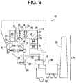
FIG. 6 is a schematic view of features of the boiler ofFIG. 1 . - As shown in
FIG. 1 , aboiler 10 includes afurnace 20 having afurnace bottom 11, anoutlet 12, anexhaust path 13 and anexhaust system 14. Theoutlet 12 is typically narrower than thefurnace 20 and is provided to allow emissions generated in the furnace to escape. Theexhaust path 13, through which the emissions travel upon exiting through theoutlet 12, is coupled to theoutlet 12 and extends first in a substantially lateral orientation with respect to thefurnace 20 and then in a substantially downward orientation with respect to thefurnace 20. Accumulated particulate matter from emissions generated in thefurnace 20 is removed from heat transfer surfaces in theexhaust path 13. Theexhaust system 14 is coupled to theexhaust path 13 and allows the emissions generated in thefurnace 20 to be exhausted to the atmosphere. While theboiler 10 is illustrated as a pulverized coal (PC) opposed wall-fired boiler, embodiments of this invention could be applied to other types of boilers as well. These include front wall-fired boilers, tangentially-fired boilers, and cyclone-fired boilers, etc. - With reference to
FIGS. 1 and2 , the furnace includes afront wall 21, aback wall 22 and side walls (not shown) that define interior surfaces of thefurnace 20, thefurnace bottom 11 and theoutlet 12. In addition, thefront wall 21, theback wall 22 and the side walls define interior surfaces of amain combustion zone 25 and areburn zone 26 disposed downstream from themain combustion zone 25. - Proximate to the
main combustion zone 25, pluralities offirst burners 23 are arranged on thefront wall 21 with pluralities ofsecond burners 24 similarly arranged on theback wall 22. In an embodiment of the invention, the first and thesecond burners mill 101 of acoal feed system 110 of a fuel delivery system, an embodiment of which will be described later with reference toFIG. 3 , to the first andsecond burners fan 50 to the first andsecond burners air manifolds air heater 53, which may heat the pumped air. The first andsecond burners main combustion zone 25. As will be described below, additional embodiments exist in which biomass is included in the first fuel. - The firing of the first and
second burners main combustion zone 25. The emissions are transported through thefurnace 20, theexhaust path 13 and theexhaust system 14 to be emitted to the atmosphere through the exhaust stack 28 (seeFIG. 6 ). - In accordance with certain embodiments of the invention, modified combustion processes in the
furnace 20 reduce amounts of the pollutants in the emissions. That is, reburn fuel, which may comprise, for example, biomass, coal and/or a combination of flexible quantities of biomass and coal, is injected intoreburn zone 26, which is disposed within thefurnace 20 and downstream from the main combustion zone, by at least onereburn injector 41. The reburn fuel reacts with and reduces amounts of the pollutants in the emissions of the main combustion zone in accordance with compositional ingredients thereof. That is, the reburn fuel reacts with and reduces nitrogen oxide emissions by converting the nitrogen oxides into molecular nitrogen. Here, the biomass in the reburn fuel is supplied from abiomass supply system 30 of the fuel delivery system, an embodiment of which will be described below with reference toFIG. 4 . Since biomass is a CO2-neutral fuel, emissions of CO2 are reduced in direct proportion to the percent of fossil fuel substituted with biomass. When biomass that contains lower amounts of sulfur and mercury compared to original coal fuel is used to provide a portion of the heat input to the boiler, the emissions of SOx and Hg are decreased relative to a coal-only firing mode. Due to the elevated concentrations of alkali and alkali earth compounds in biomass as compared to coal, biomass char produced during biomass oxidation is typically more reactive and often has higher porosity and surface area than char produced by coal oxidation. Higher reactivity and surface area of biomass char results in efficient capture of mercury released during combustion on the biomass char particles and subsequently. Additionally, chlorine content of biomass released during combustion improves mercury oxidation from its elemental form Hg0 to the oxidized form Hg2- that can subsequently be efficiently captured by methods known in field. As a result, of the above processes, utilization of biomass fuel results in decreased amount of mercury released to the atmosphere. - As shown in
FIG. 2 , thereburn zone 26 is located downstream from themain combustion zone 25 in thefurnace 20. Abooster air fan 104 and adamper 105 are coupled to the at least onereburn injector 41 to improve mixing of the reburn fuel in thereburn zone 26. While only onereburn injector 41 is shown inFIG. 2 ,additional reburn injectors 41 may be coupled to thefurnace 20 in similar or alternate locations. For example, one ormore reburn injectors 41 can be located at thefront 21,back 22, and/or side walls of thefurnace 20 so as to achieve an efficient mixing of the reburn fuel in thereburn zone 26. In any case, eachreburn injector 41 may be supplied with biomass and by separate coal feed lines designated by the arrow extending frommill 101 throughdamper 103 and toward thereburn injector 41. In addition, eachreburn injector 41 may be supplied with aseparate damper 105 to control the flow of boost air and the mixing characteristics of the reburn fuel stream injected through each of thereburn injectors 41. - In accordance with embodiments of the invention, an efficient mixing of the reburn fuel with combustion gases that are present in the
reburn zone 26 requires a substantially complete penetration of the reburn fuel into thefurnace 20. To this end, various constructions of thereburn injector 41 may be employed. In one construction, acomposite reburn injector 41, which does not mix coal and biomass particles prior to their injection into thereburn zone 26, injects coal and biomass particles into thereburn zone 26 of thefurnace 20 with different trajectories. In another construction, the necessary penetration of the reburn fuel into thereburn zone 26 can be achieved bypre-mixing reburn injectors 41 that are designed to mix coal and biomass fuel particles prior to their injection into thereburn zone 26. - To complete the combustion process, overfire air (OFA) is injected into a
burnout zone 27 of thefurnace 20, which is located downstream from thereburn zone 26. The OFA is injected through a plurality ofOFA injectors injectors furnace 20, in alternate embodiments of the invention, one or more OFA injectors can also be located downstream from theburnout zone 27 in an upper part of thefurnace 20. The injection of the OFA creates an oxygen rich and fuel lean exhaust gas that passes through theoutlet 12, theexhaust path 13 and theexhaust system 14. - A system for providing the reburn fuel to the
reburn zone 26, according to embodiments of the invention, will now be described. With reference toFIG. 3 , an exemplary embodiment of thecoal feed system 110supplies mill 101 with coal to be pulverized. An output of themill 101, which is not provided to the first andsecond burners reburn injector 41, as shown inFIGS. 1 and2 by the arrow extending from themill 101 and through thedamper 103.Fan 102 supplies air to operate themill 101 and to transport the pulverized coal through thedamper 103 and to thereburn injector 41. Thecoal feed system 110, according to an embodiment of the invention, may further include thecoal pile 111,belt feeders coal grinder 113, temporarycoal storage silo 115, and afeeder 116 to store the coal as necessary and to transport the coal to themill 101. When the reburn fuel includes the supply of the biomass along with the pulverized coal, the reduction of nitrogen oxide emissions is accompanied by at least a reduction in carbon dioxide emissions as well. - With reference to
FIG. 4 , biomass is supplied to thereburn injector 41 by thebiomass supply system 30 preferably in particle size ranges of approximately 0.2 to 2 millimeters in lengths and all nested sub-ranges therein. In this manner, the reburn fuel supplies about 20-30% of the total heat input for thefurnace 20 but 40-50% of the fuel supply. Consequently, but for advantages provided by embodiments of the present invention, a relatively large amount of biomass may be required. - Here, it is noted that the structure of the biomass supply system is highly dependent upon the nature of the biomass being used. As such, the embodiment shown in
FIG. 4 should be considered as only an exemplarybiomass supply system 30. - As shown in
FIG. 4 , biomass may be initially stored in abiomass storage device 31. Ascreening device 33 screens out very large particles while thesize reduction device 34, such as a hammermill, reduces sizes of the screened particles.Transporters 32 and 35 transport the biomass through thebiomass supply system 30 and into ahopper 36 for temporary storage. Thehopper 36 is sufficiently sized to provide for a smooth operation of thefurnace 20 over a certain period of time. For example, a capacity of thehopper 36 may provide a sufficient amount of biomass to act as fuel for a weeklong operation of thefurnace 20 or as fuel for as little as 8 hours of uninterrupted operation of thefurnace 20. From thehopper 36, the biomass is conveyed throughairlock 37 and ascrew conveyor 38 to theeductor 39. The eductor 39 mixes the biomass with a carrier gas and, subsequently, the biomass/carrier gas mixture is pneumatically conveyed to thereburn injector 41. - The carrier gas may be ambient air that is supplied by a dedicated air fan, such as dedicated air fan 40 (see
FIGS. 1 and5 ), which is coupled todamper 42, air that is routed from the air manifolds 51 and 52, steam, recirculated flue gas (RFG), inert gas, or a mixture thereof, as long as the temperature and oxygen content of the carrier gas does not risk premature ignition of the biomass. With reference toFIG. 5 , in an embodiment of the invention, a mixture of the RFG and ambient air may be used as the carrier gas. Here, the RFG is extracted from the exhaust path atpoint 54, located upstream from the air heater 53 (seeFIG. 1 ), which is used to heat air enteringair manifolds mixer 55. This ambient air may be supplied by thededicated air fan 40, which is provided in combination with thedamper 42, as noted above.Thermocouple 56, which is disposed downstream from themixer 55, may measure a temperature of the carrier gas as part of a feedback loop that is employed to control a temperature of the carrier gas. Additional RFG cleanup equipment such as cyclones or filters (not shown) can be used to reduce RFG particulate loading upstream from themixer 55. - Since a temperature of the RFG may be approximately 600 degrees Fahrenheit, with an ambient air to RFG mixing ratio of approximately 3:1, the biomass carrier gas temperature would be approximately 200 degrees Fahrenheit and safely below the biomass ignition temperature.
- Utilization of the RFG as a carrier gas enables a preheating of and, at least, a partial pre-drying of the biomass. Pre-heated and pre-died biomass fuel will react more readily when injected into the
reburn zone 26. Also, utilization of the heat content of the RFG for fuel preheating may increase an overall efficiency of thefurnace 20. Moreover, RFG extraction upstream from theair heater 53 reduces an overall exhaust gas flowrate through thePCD 60 and may increase particulate control efficiency. - In a further embodiment of the invention, where the
thermocouple 56 is employed in the feedback loop to control a temperature of the carrier gas, a single control setpoint temperature can be chosen as a carrier gas temperature. Alternatively, a number of different setpoint temperatures can be chosen, with each setpoint matched to a specific biomass feedstock. That is, as a type of biomass used with thefurnace 20 changes during the operation of thefurnace 20, different setpoint temperatures of the carrier gas may be chosen. - In accordance with embodiments of the invention, since the
reburn zone 26 of thefurnace 20 is capable of operating with biomass, pulverized coal, or a mixture of flexible quantities of biomass and pulverized coal in accordance with a number of parameters such as boiler efficiency, pollutant emissions, steam production, etc., a number of problems associated with biomass fuel availability, variability, and reliability may be resolved. - For example, to achieve high levels of nitrogen oxide emissions reductions, large amounts of biomass may be required for the reburn fuel for the
reburn zone 26 and may exceed 200,000 tons of biomass per year. The supply of such an amount of biomass depends upon seasonal availability and is subject to supply interruptions. Accordingly, in an embodiment of the invention a need for limited on-site storage of biomass is satisfied by, for example, a one-week supply of biomass. - In this case, when the biomass is available for use in the reburn fuel, the reburn fuel can comprise only biomass so as to reduce nitrogen oxide emissions in the
reburn zone 26. When the supply of the biomass cannot be maintained, the reburn fuel can comprise a mixture of flexible quantities of biomass and coal. If the biomass supply is exhausted, the reburn fuel can comprise only coal. In addition, the flexible quantities of both of the biomass and the coal may be varied regardless of the amount of available biomass to alter boiler performance in accordance with changingfurnace 20 conditions. For example, if the supplied biomass has a high moisture content, steam production inboiler 10 may decrease, leading to undesirable boiler derate. Here, negative impacts on thefurnace 20 can be mitigated or avoided if a portion of the high-moisture biomass is substituted with coal. - To these ends, a control system (not shown) may be employed to adjust a ratio of biomass to coal in the reburn fuel mixture. For example, with reference to
FIG. 4 , an operational speed of a variable-speed feeder 38, which is included in thebiomass supply system 30, can adjust a biomass flow rate into theeductor 39. As a result, the reburn fuel mixed in theeductor 39 will have a lower biomass concentration. Similarly, a coal flow rate is controllable byfeeder 116, which is included in thecoal feed system 110, and/ordamper 103, which is coupled to thecoal feed system 110. Again, the operational speed of thefeeder 116 or the setting of thedamper 103 can adjust an amount of coal supplied to thereburn injector 41. As a result, a concentration of coal in the reburn fuel can be adjusted. - The control system may also ensure that the
reburn zone 26 of thefurnace 20 is supplied with coal or biomass exclusively. For example, with thebiomass feeding system 30 offline, thefurnace 20 can continue to operate with only coal being used as the first fuel and the reburn fuel. Also, the control system may change the proportion of the biomass or coal in the reburn fuel in response to operational considerations based on feedback from a thermocouple 57 (seeFIG. 4 ) located downstream from theburnout zone 27 in theoutlet 12. - In addition, as shown in
FIG. 5 , adiverter 43, including a three-way valve, may allow for a diversion of all or a portion of the biomass/carrier gas mixture to a subset ofburners 29 that includes at least one of the first andsecond burners diverter 43 would be disposed downstream from themixer 55 and theeductor 39 and may provide for an additionally flexible operation of thefurnace 20. That is, if a temporary interruption of reburn operations (for example, to perform maintenance or repair of the reburn injector 41) is desired while still utilizing a fuel including biomass to reduce emissions from thefurnace 20, the biomass/carrier gas mixture may be supplied to the one or more of themain burners main combustion zone 25. - In this case, the diverted biomass/carrier gas mixture, which is designated by the dotted line extending from the
diverter 43 to thevalve 44 and the subset ofburners 29, can either be fired through the subset ofburners 29 alone or in combination with the coal fuel. When the biomass/carrier gas mixture is to be fired alone, the coal fuel supply (designated by arrow, C) is cut off from the subset ofburners 29 by thevalve 44. When the coal and the biomass/carrier gas mixture are to be fired together, the subset ofburners 29 may be required to comprise composite burners, such as concentric burners, in which coal is fed through a center pipe and biomass is fed through a concentric annular pipe. Alternatively, the coal and biomass/carrier gas mixture may also be pre-mixed upstream from subset ofburners 29 or inside the subset ofburners 29 themselves. Retrofitting the first andsecond burners burners 29 for the diverted biomass/carrier gas mixture. - With reference now to
FIGS. 5 and6 , in embodiments of the invention, an increased mass flowrate of exhaust gas may occur as the exhaust gas travels through theexhaust path 13 and theexhaust system 14 due to the use of biomass as either a reburn fuel or a first fuel. In addition, reburn operations of thereburn zone 26 of thefurnace 20 tend to change temperature distributions in theboiler 10, and can result in a changing temperature of the exhaust gas. Therefore,furnace 20 operations powered by biomass may negatively impact downstream boiler equipment such as thePCD 60. - According to an embodiment of the invention, the
PCD 60 may comprise an electrostatic precipitator (ESP). Since biomass may have a lower ash content as compared to coals, it is expected that using biomass as a reburn fuel in thereburn zone 26 will reduce ash loading at an inlet of thePCD 60. However, since the use of biomass as a reburn fuel may lead to an increased exhaust gas flowrate, a reduced efficiency of particle collection may result.The exhaust gas temperature at an inlet of thePCD 60 may increase or decrease as a result of thefurnace 20 operation. Here, PCD 60 (i.e., ESP) operating parameters, such as voltage, current density, rapping frequency, and so on, can be adjusted to account for the impacts caused by thefurnace 20 operation. In particular,PCD 60 controls may be linked to the control system to integrate thefurnace 20 and thePCD 60 operations. - Chemical and physical properties of the ash formed by combusting biomass differ significantly from those of the ash formed by combusting coal. Therefore, it is expected that a substitution of a portion of the coal fuel with biomass fuel will affect ash formation. That is, since the reburn fuel, including the biomass, is injected into the
reburn zone 26 downstream from themain combustion zone 25, it is expected that biomass combustion will affect a formation of ash in thefurnace 20. To this end, as shown inFIGS. 5 and6 , deposit control elements 70-79, which can include sootblowers, acoustic horns, pulsed detonation cleaners, etc, are typically located at deposit control locations in the vicinity of the heat transfer surfaces 80-85, such as superheater and reheater tube banks and platens. - The operation of the deposit control elements 70-79 may then be adjusted based on the type, amount, and chemical properties of the reburn fuel, since trajectories of coal particles differ from trajectories of biomass particles such that ash deposit characteristics and formation rates will exhibit non-uniform spatial distributions. For example, if it is expected that biomass ash particles will primarily concentrate in an upper part of cross section A-A, in the
exhaust path 13 while coal ash particles will primarily concentrate in a bottom part of the cross section, different deposit removal frequencies may be employed for thedeposit removal element 74 as compared to thedeposit removal element 76 to achieve an optimum deposit control. A deposit removal frequency for each deposit removal element or subset thereof may be determined and controlled based on the characteristics of the main fuel (i.e., pulverized coal) and the reburn fuel (i.e., coal/biomass mixture) and operating conditions of thefurnace 20. - This written description uses examples to disclose the invention, including the perferred mode, and to enable any person skilled in the art to practice the invention, including making and using any devices or systems and performing any incorporated methods. The patentable scope of the invention is defined by the claims, and may include other examples that occur to those skilled in the art.
Claims (8)
- A fuel flexible furnace (20), comprising:a main combustion zone (25);a reburn zone (26) downstream from the main combustion zone (25); anda burnout zone (27) disposed downstream from the reburn zone (26);a plurality of overfire air (OFA) injectors (106, 107) to inject OFA, including oxygen to mix with emissions from the reburn zone (26) and the main combustion zone (25), into the burnout zone (27);a delivery system (30, 110) operably coupled to supplies of biomass and coal and configured to deliver the biomass and the coal as ingredients of first and reburn fuels to the main combustion zone (25) and the reburn zone (26), with each fuel including flexible quantities of the biomass and/or the coal, wherein the flexible quantities are variable with the furnace (20) in an operating condition; characterized bya control system configured to adjust a ratio of biomass to coal in the reburn fuel delivered to the reburn zone (26); anda thermocouple (57) disposed downstream from the burnout zone (27) in an outlet (12) of the furnace (20), wherein the control system configured to adjust a ratio of biomass to coal in the reburn fuel delivered to the reburn zone (26) based on feedback from the thermocouple (57).
- The furnace (20) according to claim 1, wherein the delivery system (30, 110) comprises:burners (23, 24), to be supplied with the first and the reburn fuels, which are configured to fire into the main combustion zone (25); andat least one injector (41) configured to inject the first and the reburn fuels into the reburn zone (26).
- The furnace according to any preceding claim, further comprising a combination of a booster air fan (104) and flow control elements (105) to increase a level of mixing of the ingredients of the reburn fuel prior to the injection thereof into the reburn zone (26) by the at least one injector (41).
- The furnace (20) according to any preceding claim, wherein the flexible quantities of the biomass and the coal in the reburn fuel comprise:only biomass to reduce amounts of nitrogen oxides generated in the reburn zone,only coal when a supply of the biomass is exhausted, anda combination of the biomass and the coal when a supply of the biomass is diminished and/or to allow for an adjustment of a performance of the furnace (20).
- The furnace (20) according to any preceding claim, further comprising:an outlet (12) of the furnace (20) disposed downstream from the burnout zone (27);an exhaust path (113) coupled to the outlet (12), in which particulate matter, which is carried by the emissions from the main combustion zone (25) and the reburn zone (26), is removed from heat transfer surfaces (80-85) of the furnace (20); andan exhaust system (14), downstream from the exhaust path (13), through which the emissions are exhausted to an exterior of a boiler (10) in which the furnace (20) is installed.
- The furnace (20) according to the preceding claim, wherein the exhaust path (13) comprises:a plurality of deposit control elements (70-79) to remove ash deposits from the heat transfer surfaces (80-85), whereinthe deposit control elements (70-79) are disposed in deposit control locations in accordance with ash forming characteristics of the first fuel and the reburn fuel.
- The furnace (20) according to any of the preceding claims 5, 6 wherein the exhaust system (14) comprises:
an electrostatic precipitator (60) to collect the particulate matter from the emissions; and an exhaust stack (28) to exhaust the emissions to the exterior of the boiler (10). - A method of operating a fuel flexible furnace (20) of a boiler (10), comprising:combusting first and reburn fuels in a main combustion zone (25) of the furnace (20);injecting the first and reburn fuels into a reburn zone (26) of the furnace (20), which is located downstream from the main combustion zone (25); andsupplying flexible quantities of biomass and/or coal as ingredients of the first and the reburn fuels, wherein the flexible quantities are variable during an operating condition of the furnace (20);injecting overfire air (OFA) into a burnout zone (27) disposed downstream of the reburn zone (26), thereby mixing oxygen with emissions from the reburn zone (26) and the main combustion zone (25); and characterized byadjusting a ratio of biomass to coal in the reburn fuel delivered to the reburn zone (26) in response to feedback from a thermocouple (57) disposed downstream from the burnout zone (27) in an outlet (12) of the furnace (20).
Priority Applications (1)
| Application Number | Priority Date | Filing Date | Title |
|---|---|---|---|
| PL08164195T PL2039994T3 (en) | 2007-09-24 | 2008-09-12 | Method and apparatus for operating a fuel flexible furnace to reduce pollutants in emissions |
Applications Claiming Priority (2)
| Application Number | Priority Date | Filing Date | Title |
|---|---|---|---|
| US99974907P | 2007-09-24 | 2007-09-24 | |
| US11/950,615 US8015932B2 (en) | 2007-09-24 | 2007-12-05 | Method and apparatus for operating a fuel flexible furnace to reduce pollutants in emissions |
Publications (3)
| Publication Number | Publication Date |
|---|---|
| EP2039994A2 EP2039994A2 (en) | 2009-03-25 |
| EP2039994A3 EP2039994A3 (en) | 2014-02-19 |
| EP2039994B1 true EP2039994B1 (en) | 2018-07-25 |
Family
ID=40070608
Family Applications (1)
| Application Number | Title | Priority Date | Filing Date |
|---|---|---|---|
| EP08164195.3A Revoked EP2039994B1 (en) | 2007-09-24 | 2008-09-12 | Method and apparatus for operating a fuel flexible furnace to reduce pollutants in emissions |
Country Status (5)
| Country | Link |
|---|---|
| US (1) | US8015932B2 (en) |
| EP (1) | EP2039994B1 (en) |
| CN (1) | CN101398168B (en) |
| CA (1) | CA2639475C (en) |
| PL (1) | PL2039994T3 (en) |
Families Citing this family (32)
| Publication number | Priority date | Publication date | Assignee | Title |
|---|---|---|---|---|
| US8015932B2 (en) | 2007-09-24 | 2011-09-13 | General Electric Company | Method and apparatus for operating a fuel flexible furnace to reduce pollutants in emissions |
| ES2420558T3 (en) * | 2008-03-06 | 2013-08-23 | Ihi Corporation | Method and apparatus for monitoring the supply of oxygen in a boiler |
| JP5051721B2 (en) * | 2008-05-16 | 2012-10-17 | 川崎重工業株式会社 | Biomass mixed combustion pulverized coal fired boiler |
| US8574329B2 (en) * | 2008-12-11 | 2013-11-05 | General Electric Company | Method of operating a gasifier |
| US8617271B2 (en) * | 2008-12-11 | 2013-12-31 | General Electric Company | Method of retrofitting a coal gasifier |
| WO2010107914A2 (en) * | 2009-03-18 | 2010-09-23 | Palmer Labs, Llc | Biomass production and processing and methods of use thereof |
| JP2010242999A (en) * | 2009-04-02 | 2010-10-28 | Babcock Hitachi Kk | Method and device for directly pulverizing and burning woody biomass and boiler system |
| US8906301B2 (en) * | 2009-09-15 | 2014-12-09 | General Electric Company | Combustion control system and method using spatial feedback and acoustic forcings of jets |
| WO2011106550A2 (en) * | 2010-02-26 | 2011-09-01 | Global Greensteam Llc | Biomass-to-energy combustion method |
| JP5645469B2 (en) * | 2010-05-14 | 2014-12-24 | 三菱重工業株式会社 | Biomass crusher and biomass / coal co-firing system |
| JP5645468B2 (en) | 2010-05-14 | 2014-12-24 | 三菱重工業株式会社 | Biomass crusher and biomass / coal co-firing system |
| JP2011245357A (en) * | 2010-05-21 | 2011-12-08 | Mitsubishi Heavy Ind Ltd | Biomass pulverizing device and biomass/coal co-combustion system |
| MY185043A (en) * | 2011-01-31 | 2021-04-30 | Ihi Corp | Burner device for high-temparature air combustion |
| US8309045B2 (en) | 2011-02-11 | 2012-11-13 | General Electric Company | System and method for controlling emissions in a combustion system |
| US20120244479A1 (en) * | 2011-03-22 | 2012-09-27 | General Electric Company | Combustion System Using Recycled Flue Gas to Boost Overfire Air |
| EP3690315A1 (en) * | 2011-04-22 | 2020-08-05 | Accordant Energy, LLC | A process for cogasifying and cofiring engineered fuel with coal |
| US20130087085A1 (en) * | 2011-10-11 | 2013-04-11 | Peter Rugg | System and Method for Cleaning Coal and Biomass in Efficient Integration with Fuel Delivery to a Boiler |
| JP5886031B2 (en) * | 2011-12-26 | 2016-03-16 | 川崎重工業株式会社 | Biomass fuel combustion method |
| JP5848983B2 (en) * | 2012-02-20 | 2016-01-27 | 新日鐵住金株式会社 | Co-firing method of pulverized coal and biomass fuel and pulverized coal fired boiler furnace |
| US20130255551A1 (en) * | 2012-03-27 | 2013-10-03 | American Air Liquide, Inc. | Biomass Combustion |
| US9035116B2 (en) | 2012-08-07 | 2015-05-19 | Kior, Inc. | Biomass feed system including gas assist |
| HUP1200612A2 (en) * | 2012-10-24 | 2014-04-28 | Karoly Robert Foeiskola | Biomass boiler system |
| CA2887282C (en) * | 2012-10-24 | 2020-07-14 | Maralto Environmental Technologies Ltd. | Heat exchanger and method for heating a fracturing fluid |
| JP5881584B2 (en) * | 2012-11-12 | 2016-03-09 | 三菱日立パワーシステムズ株式会社 | boiler |
| JP2014238192A (en) * | 2013-06-06 | 2014-12-18 | 株式会社神戸製鋼所 | Method for mixedly combusting biomass fuel and coal system fuel, and biomass-coal system fuel |
| JP6081341B2 (en) * | 2013-10-25 | 2017-02-15 | 三菱日立パワーシステムズ株式会社 | boiler |
| US9702548B2 (en) * | 2014-06-16 | 2017-07-11 | Biomass Energy Enhancements, Llc | System for co-firing cleaned coal and beneficiated organic-carbon-containing feedstock in a coal combustion apparatus |
| CN105674232B (en) * | 2014-11-19 | 2017-11-24 | 武汉江河长能源科技有限公司 | A kind of biomass micron fuel hot industry boiler of clean and effective |
| CN104501200B (en) * | 2014-11-19 | 2017-06-13 | 华中科技大学 | Biomass micron fuel high-temperature cleaning combustion method based on adiabatic combustion condition |
| CN105020725B (en) * | 2015-07-08 | 2016-06-08 | 南京常荣声学股份有限公司 | A kind of ash remover of boiler based on combined-flow |
| CN114636148A (en) * | 2022-02-21 | 2022-06-17 | 合肥工业大学智能制造技术研究院 | A biomass fuel and coal co-combustion device |
| CN116447587A (en) * | 2023-03-01 | 2023-07-18 | 华北水利水电大学 | A biomass high-temperature prepyrolysis high-efficiency coupled combustion and ultra-low NOx emission system |
Citations (4)
| Publication number | Priority date | Publication date | Assignee | Title |
|---|---|---|---|---|
| US20030143128A1 (en) | 2002-01-25 | 2003-07-31 | Lanier William Steven | Process and system to reduce mercury emission |
| US20040139894A1 (en) | 2003-01-22 | 2004-07-22 | Joel Vatsky | Burner system and method for mixing a plurality of solid fuels |
| US6973883B1 (en) | 2001-03-22 | 2005-12-13 | The Texas A&M University System | Reburn system with feedlot biomass |
| EP2039994A2 (en) | 2007-09-24 | 2009-03-25 | General Electric Company | Method and apparatus for operating a fuel flexible furnace to reduce pollutants in emissions |
Family Cites Families (8)
| Publication number | Priority date | Publication date | Assignee | Title |
|---|---|---|---|---|
| US4488516A (en) * | 1983-11-18 | 1984-12-18 | Combustion Engineering, Inc. | Soot blower system |
| US5121600A (en) * | 1990-06-21 | 1992-06-16 | Energeo, Inc. | Transportable electrical power generating system fueled by organic waste |
| US5378083A (en) * | 1993-07-13 | 1995-01-03 | Astec Industries, Inc. | Dust recycling for soil remediation system |
| US5720165A (en) * | 1995-09-21 | 1998-02-24 | Bioten Gp | System for burning biomass to produce hot gas |
| US6699029B2 (en) * | 2001-01-11 | 2004-03-02 | Praxair Technology, Inc. | Oxygen enhanced switching to combustion of lower rank fuels |
| US7168947B2 (en) * | 2004-07-06 | 2007-01-30 | General Electric Company | Methods and systems for operating combustion systems |
| DE102004049491A1 (en) * | 2004-10-11 | 2006-04-20 | Alstom Technology Ltd | premix |
| US7544339B2 (en) * | 2007-03-27 | 2009-06-09 | General Electric Company | Method and apparatus for removing mercury from combustion exhaust gas |
-
2007
- 2007-12-05 US US11/950,615 patent/US8015932B2/en active Active
-
2008
- 2008-09-11 CA CA2639475A patent/CA2639475C/en not_active Expired - Fee Related
- 2008-09-12 PL PL08164195T patent/PL2039994T3/en unknown
- 2008-09-12 EP EP08164195.3A patent/EP2039994B1/en not_active Revoked
- 2008-09-24 CN CN200810165666.7A patent/CN101398168B/en not_active Expired - Fee Related
Patent Citations (4)
| Publication number | Priority date | Publication date | Assignee | Title |
|---|---|---|---|---|
| US6973883B1 (en) | 2001-03-22 | 2005-12-13 | The Texas A&M University System | Reburn system with feedlot biomass |
| US20030143128A1 (en) | 2002-01-25 | 2003-07-31 | Lanier William Steven | Process and system to reduce mercury emission |
| US20040139894A1 (en) | 2003-01-22 | 2004-07-22 | Joel Vatsky | Burner system and method for mixing a plurality of solid fuels |
| EP2039994A2 (en) | 2007-09-24 | 2009-03-25 | General Electric Company | Method and apparatus for operating a fuel flexible furnace to reduce pollutants in emissions |
Also Published As
| Publication number | Publication date |
|---|---|
| PL2039994T3 (en) | 2018-11-30 |
| CA2639475C (en) | 2015-12-29 |
| CN101398168B (en) | 2013-04-17 |
| US20090078175A1 (en) | 2009-03-26 |
| US8015932B2 (en) | 2011-09-13 |
| EP2039994A2 (en) | 2009-03-25 |
| CN101398168A (en) | 2009-04-01 |
| EP2039994A3 (en) | 2014-02-19 |
| CA2639475A1 (en) | 2009-03-24 |
Similar Documents
| Publication | Publication Date | Title |
|---|---|---|
| CA2639475C (en) | Method and apparatus for operating a fuel flexible furnace to reduce pollutants in emissions | |
| CN100343576C (en) | Oxygen enhanced combustion of lower rank fuels | |
| CN101784839B (en) | System and method for minimizing nitrogen oxide (NOx) emissions in cyclone combustors | |
| EP2623861A1 (en) | Combustion system and method for operating same | |
| US7833315B2 (en) | Method and system for reducing mercury emissions in flue gas | |
| BG60359B2 (en) | Group concentric tangential firing system and method for its operation | |
| US8695516B2 (en) | Pollution abatement process for fossil fuel-fired boilers | |
| KR20130103774A (en) | Apparatus and method of controlling the thermal performance of an oxygen-fired boiler | |
| US20100263577A1 (en) | Pollution abatement process for fossil fuel-fired boilers | |
| EP1000300A1 (en) | Reburn process | |
| EP2751484B1 (en) | Combustion apparatus with indirect firing system | |
| US20160146462A1 (en) | PLANT, COMBUSTION APPARATUS, AND METHOD FOR REDUCTION OF NOx EMISSIONS | |
| EP1936269B1 (en) | Combustion furnace and combustion method using oxy-fuel reburn burners | |
| KR950007382B1 (en) | Sulfur removal by sorbent injection in secondary combustion zones | |
| RU2428632C2 (en) | Flaring method of pulverised fuel and device for method's implementation | |
| CN118871715A (en) | Pulverized fuel burners | |
| JPS5960107A (en) | Low nox burning device | |
| CN111609676A (en) | Denitration process for cooperatively treating garbage by cement kiln | |
| US7662353B2 (en) | Methods and systems for removing mercury from combustion flue gas | |
| CN101201162A (en) | Combustion system and process | |
| US20090123883A1 (en) | Swirling-type furnace operating method and a swirling-type furnace | |
| Liu | Gaseous Emission Control | |
| RU1774131C (en) | Method of preparation and combustion of solid fuel |
Legal Events
| Date | Code | Title | Description |
|---|---|---|---|
| PUAI | Public reference made under article 153(3) epc to a published international application that has entered the european phase |
Free format text: ORIGINAL CODE: 0009012 |
|
| AK | Designated contracting states |
Kind code of ref document: A2 Designated state(s): AT BE BG CH CY CZ DE DK EE ES FI FR GB GR HR HU IE IS IT LI LT LU LV MC MT NL NO PL PT RO SE SI SK TR |
|
| AX | Request for extension of the european patent |
Extension state: AL BA MK RS |
|
| PUAL | Search report despatched |
Free format text: ORIGINAL CODE: 0009013 |
|
| AK | Designated contracting states |
Kind code of ref document: A3 Designated state(s): AT BE BG CH CY CZ DE DK EE ES FI FR GB GR HR HU IE IS IT LI LT LU LV MC MT NL NO PL PT RO SE SI SK TR |
|
| AX | Request for extension of the european patent |
Extension state: AL BA MK RS |
|
| RIC1 | Information provided on ipc code assigned before grant |
Ipc: F23C 1/00 20060101AFI20140114BHEP |
|
| 17P | Request for examination filed |
Effective date: 20140819 |
|
| RBV | Designated contracting states (corrected) |
Designated state(s): AT BE BG CH CY CZ DE DK EE ES FI FR GB GR HR HU IE IS IT LI LT LU LV MC MT NL NO PL PT RO SE SI SK TR |
|
| AKX | Designation fees paid |
Designated state(s): DE DK GB PL |
|
| 17Q | First examination report despatched |
Effective date: 20160909 |
|
| STAA | Information on the status of an ep patent application or granted ep patent |
Free format text: STATUS: EXAMINATION IS IN PROGRESS |
|
| GRAP | Despatch of communication of intention to grant a patent |
Free format text: ORIGINAL CODE: EPIDOSNIGR1 |
|
| STAA | Information on the status of an ep patent application or granted ep patent |
Free format text: STATUS: GRANT OF PATENT IS INTENDED |
|
| GRAJ | Information related to disapproval of communication of intention to grant by the applicant or resumption of examination proceedings by the epo deleted |
Free format text: ORIGINAL CODE: EPIDOSDIGR1 |
|
| STAA | Information on the status of an ep patent application or granted ep patent |
Free format text: STATUS: EXAMINATION IS IN PROGRESS |
|
| INTG | Intention to grant announced |
Effective date: 20180412 |
|
| GRAR | Information related to intention to grant a patent recorded |
Free format text: ORIGINAL CODE: EPIDOSNIGR71 |
|
| GRAS | Grant fee paid |
Free format text: ORIGINAL CODE: EPIDOSNIGR3 |
|
| STAA | Information on the status of an ep patent application or granted ep patent |
Free format text: STATUS: GRANT OF PATENT IS INTENDED |
|
| INTC | Intention to grant announced (deleted) | ||
| INTG | Intention to grant announced |
Effective date: 20180515 |
|
| GRAA | (expected) grant |
Free format text: ORIGINAL CODE: 0009210 |
|
| STAA | Information on the status of an ep patent application or granted ep patent |
Free format text: STATUS: THE PATENT HAS BEEN GRANTED |
|
| AK | Designated contracting states |
Kind code of ref document: B1 Designated state(s): DE DK GB PL |
|
| REG | Reference to a national code |
Ref country code: GB Ref legal event code: FG4D |
|
| REG | Reference to a national code |
Ref country code: DE Ref legal event code: R096 Ref document number: 602008056127 Country of ref document: DE |
|
| REG | Reference to a national code |
Ref country code: DE Ref legal event code: R026 Ref document number: 602008056127 Country of ref document: DE |
|
| PLBI | Opposition filed |
Free format text: ORIGINAL CODE: 0009260 |
|
| PLAX | Notice of opposition and request to file observation + time limit sent |
Free format text: ORIGINAL CODE: EPIDOSNOBS2 |
|
| 26 | Opposition filed |
Opponent name: BILFINGER ENGINEERING & TECHNOLOGIES GMBH Effective date: 20190425 |
|
| PG25 | Lapsed in a contracting state [announced via postgrant information from national office to epo] |
Ref country code: DK Free format text: LAPSE BECAUSE OF FAILURE TO SUBMIT A TRANSLATION OF THE DESCRIPTION OR TO PAY THE FEE WITHIN THE PRESCRIBED TIME-LIMIT Effective date: 20180725 |
|
| PLBB | Reply of patent proprietor to notice(s) of opposition received |
Free format text: ORIGINAL CODE: EPIDOSNOBS3 |
|
| REG | Reference to a national code |
Ref country code: DE Ref legal event code: R103 Ref document number: 602008056127 Country of ref document: DE Ref country code: DE Ref legal event code: R064 Ref document number: 602008056127 Country of ref document: DE |
|
| PGFP | Annual fee paid to national office [announced via postgrant information from national office to epo] |
Ref country code: GB Payment date: 20210820 Year of fee payment: 14 Ref country code: PL Payment date: 20210820 Year of fee payment: 14 Ref country code: DE Payment date: 20210818 Year of fee payment: 14 |
|
| RDAF | Communication despatched that patent is revoked |
Free format text: ORIGINAL CODE: EPIDOSNREV1 |
|
| RDAG | Patent revoked |
Free format text: ORIGINAL CODE: 0009271 |
|
| STAA | Information on the status of an ep patent application or granted ep patent |
Free format text: STATUS: PATENT REVOKED |
|
| 27W | Patent revoked |
Effective date: 20210924 |
|
| GBPR | Gb: patent revoked under art. 102 of the ep convention designating the uk as contracting state |
Effective date: 20210924 |