EP2039604A2 - Verfahren zur Bestimmung des Abstands zwischen zwei Aussenlasten an einem Flugzeug oder Flugkörper bei der Abtrennung einer der beiden Aussenlasten - Google Patents
Verfahren zur Bestimmung des Abstands zwischen zwei Aussenlasten an einem Flugzeug oder Flugkörper bei der Abtrennung einer der beiden Aussenlasten Download PDFInfo
- Publication number
- EP2039604A2 EP2039604A2 EP08016066A EP08016066A EP2039604A2 EP 2039604 A2 EP2039604 A2 EP 2039604A2 EP 08016066 A EP08016066 A EP 08016066A EP 08016066 A EP08016066 A EP 08016066A EP 2039604 A2 EP2039604 A2 EP 2039604A2
- Authority
- EP
- European Patent Office
- Prior art keywords
- magnetic field
- external loads
- mmd
- determined
- distance
- Prior art date
- Legal status (The legal status is an assumption and is not a legal conclusion. Google has not performed a legal analysis and makes no representation as to the accuracy of the status listed.)
- Granted
Links
Images


Classifications
-
- B—PERFORMING OPERATIONS; TRANSPORTING
- B64—AIRCRAFT; AVIATION; COSMONAUTICS
- B64D—EQUIPMENT FOR FITTING IN OR TO AIRCRAFT; FLIGHT SUITS; PARACHUTES; ARRANGEMENT OR MOUNTING OF POWER PLANTS OR PROPULSION TRANSMISSIONS IN AIRCRAFT
- B64D1/00—Dropping, ejecting, releasing or receiving articles, liquids, or the like, in flight
- B64D1/02—Dropping, ejecting, or releasing articles
- B64D1/04—Dropping, ejecting, or releasing articles the articles being explosive, e.g. bombs
-
- G—PHYSICS
- G01—MEASURING; TESTING
- G01B—MEASURING LENGTH, THICKNESS OR SIMILAR LINEAR DIMENSIONS; MEASURING ANGLES; MEASURING AREAS; MEASURING IRREGULARITIES OF SURFACES OR CONTOURS
- G01B7/00—Measuring arrangements characterised by the use of electric or magnetic techniques
- G01B7/14—Measuring arrangements characterised by the use of electric or magnetic techniques for measuring distance or clearance between spaced objects or spaced apertures
Definitions
- the invention relates to a method for determining the distance between two external loads on an aircraft or missile, in the separation of one of the two external loads.
- MMD minimum miss distance
- the invention has for its object to provide a generic method for distance determination, which can be installed with little effort and which also produces only low aerodynamic interference.
- the use of one or more magnetic field sensors is proposed for distance measurement. This is preferably attached to the adjacent, during the separation process stationary external load. At the separated external load itself one or more magnets are arranged. By using several sensors, the accuracy can be increased.
- a magnetic field sensor As a magnetic field sensor, a commercially available sensor can be used (for example, Philipps Semiconductor KMZ Series). It is preferably a passive sensor.
- the field strength measured by the sensor is recorded in time. Based on a corresponding calibration, in addition to the time of the MMD, the MMD itself can be determined directly from the sensor signal.
- only the time of maximum field strength is initially determined from the sensor signal. This corresponds to the time of maximum approximation. This information is then used to select the associated video frame from the camera recording of the separation process. From this camera image, the MMD can then be determined.
- Fig. 1 shows the underside of a combat aircraft, on which two outer loads A1, A2 are arranged relatively close to each other.
- External load A1 can be, for example, an air-to-air Raktete, external load A2 a bomb. External load A1 is disconnected. The corresponding direction of movement is shown.
- External load T is an external tank of the aircraft.
- the Fig. 1 shows the external load A1 both in its installation position A10 near the fuselage as well as in four snapshots A11, A12, A13, A14, where it comes closest to the other external load A2.
- the other external load A2 does not change its position during the separation process of A1.
- the minimum distance MMD between the two outer loads A1, A2 is in Fig. 2 located.
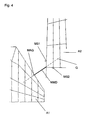
- Magnetic field sensors and magnets are generally arranged at geometrical locations on adjacent external loads A1, A2 at which the occurrence of the MMD is to be expected. Like from the Fig. 3 and 4 is clearly visible, passive magnetic field sensors MS1, MS2 are arranged to measure the distance at the side edge and the trailing edge of the wing of the external load A2. At the front edge of the wing of the separated external load A1, a small magnet MAG is arranged, which has dimensions in the millimeter range (eg edge lengths 2 x 4 X 6 mm). Since the sensors MS can be made very small (eg with edge lengths 2 X 5 X 5 mm) aerodynamic disturbances will remain very low.
- the two sensors MS1, MS2 are advantageously arranged symmetrically at right angles to a straight line G which is defined by the expected connection line of the two external loads A1, A2 when the MMD occurs.
- the magnet MAG lies on the line G.
- the magnet and the magnetic field sensor are preferably attached respectively to the geometrical locations of the external loads at which the occurrence of the MMD is to be expected (preferably on the basis of FIG Fig. 4 defined straight line G).
- a plurality of magnetic field sensors can be used to generate a larger spatial extent of the magnetic field (either together with one or more magnetic field sensors).
- the magnets can, for example, successively on the in Fig. 4 be defined straight line G, while the magnetic field sensors are symmetrical to the straight line G or lie in the case of only one magnetic field sensor on the straight line G.
- known positions of magnetic field sensors MS1, MS2 and magnet MAG can be determined from the signals of the magnetic field sensors both the time of the MMD and the MMD itself.
- a camera CAM ( Fig. 2 ) with viewing direction CP ( Fig. 1 ) to observe the separation operation of the outside load A1. Your line of sight is directed to the area where the MMD is expected.
- the value of the MMD can be determined from the associated camera image with the time of the MMD determined by means of magnetic field sensors.
Landscapes
- Engineering & Computer Science (AREA)
- Aviation & Aerospace Engineering (AREA)
- Physics & Mathematics (AREA)
- General Physics & Mathematics (AREA)
- Measurement Of Length, Angles, Or The Like Using Electric Or Magnetic Means (AREA)
Abstract
Description
- Die Erfindung betrifft ein Verfahren zur Bestimmung des Abstands zwischen zwei Außenlasten an einem Flugzeug oder Flugkörper, bei der Abtrennung einer der beiden Außenlasten.
- Bei modernen Kampflugzeugen sind die Außenlasten (insbesondere Lenkflugkörper, Raketen, Bomben) typischerweise sehr dicht beieinander angeordnet. Um die sichere Abtrennung einer Außenlast zu ermöglichen, sind bestimmte Mindestabstände (im Bereich > 2 inches) zu den übrigen Außenlasten am Flugkörper während des gesamten Abtrennvorgangs einzuhalten. Die Einhaltung dieser Mindestabstände muss in Flugversuchen nachgewiesen werden.
- Die Abstandermittlung wird üblicherweise mit Hilfe von Videoaufzeichnungen durchgeführt. Allerdings ist zur korrekten Auswertung des Filmes die Kenntnis des genauen Zeitpunktes für das Auftreten der kleinsten Distanz, Minimum Miss Distance (MMD), unabdingbar. Dies ist erforderlich, weil die Kamera einer perspektivischen Verzerrung unterliegt und somit eine ausreichend genaue Zuordnung des MMD-Zeitpunkts häufig nicht möglich ist.
- Der Erfindung liegt die Aufgabe zugrunde, ein gattungsgemäßes Verfahren zur Abstandsermittlung zu schaffen, welches mit nur geringem Aufwand installiert werden kann und welches außerdem nur geringe aerodynamische Interferenzen erzeugt.
- Diese Aufgabe wird mit dem Verfahren nach Anspruch 1 gelöst. Vorteilhafte Ausgestaltungen der Erfindung sind Gegenstände von Unteransprüchen.
- Erfindungsgemäß wird zur Abstandsmessung der Einsatz eines oder mehrerer Magnetfeldsensoren vorgeschlagen. Dieser wird bevorzugt an der benachbarten, während des Abtrennvorgangs stationären Außenlast angebracht. An der abzutrennenden Außenlast selbst sind ein oder mehrere Magnete angeordnet. Durch den Einsatz mehrerer Sensoren kann die Genauigkeit erhöht werden.
- Als Magnetfeldsensor kann ein handelsüblicher Sensor verwendet werden (z.B. Philipps Semiconductor KMZ Series). Es handelt sich dabei bevorzugt um einen passiven Sensor.
- Die vom Sensor gemessene Feldstärke wird zeitlich aufgezeichnet. Unter Zugrundlegung einer entsprechenden Eichung kann neben dem Zeitpunkt des MMD auch der MMD selbst unmittelbar aus dem Sensorsignal bestimmt werden.
- In einer alternativen Ausführung wird aus dem Sensorsignal zunächst nur der Zeitpunkt der maximalen Feldstärke ermittelt. Dieser entspricht dem Zeitpunkt der maximalen Annäherung. Diese Information dient dann der Auswahl des zugehörigen Video-Frames aus der Kamera-Aufzeichnung des Abtrennvorgangs. Aus diesem Kamerabild kann dann die MMD bestimmt wird.
- Das erfindungsgemäße Verfahren kann sowohl an einem bemannten Flugzeug als auch einem unbemannten Flugkörper (Drohnen, UAV = unmanned aerial vehicle) zur Anwendung kommen.
- Der erfindungsgemäße Einsatz eines Magnetfelssensors führt zu erheblichen Vorteilen:
- Aufgrund geringer Abmessungen der Sensoren ist die aerodynamische Interferenz, die das Trennungsverhalten des Flugkörpers beeinflusst, nur gering.
- Es sind keinerlei mechanische Teile vorhanden, die Flatter- oder Vibrationsprobleme induzieren und das Messsignal unbrauchbar machen könnten.
- Es sind keinerlei elektronische Prelleffekte zu erwarten.
- Es wird eine erheblich leichtere Installation unter Flight Test Instrumentation (FTI) Aspekten ermöglicht.
- Konkrete Ausführungen der Erfindung werden anhand unter Bezugnahme auf Fig. näher erläutert:
- Fig. 1
- zeigt in Rückansicht (Blickrichtung von hinten parallel zur Flugzeuglängsachse) mehrere Außenlasten an der Unterseite eines Kampflugzeugs.
- Fig. 2
- zeigt dieselbe Konfiguration gesehen von unten (Blickrichtung parallel zur Flugzeughochachse -
Fig. 2 nicht maßstabsgerecht zuFig. 1 ). - Fig. 3
- zeigt den Bereich aus
Fig. 1 , in dem sich die beiden Außenlasten am nächsten kommen, in vergrößertem Maßstab. - Fig. 4
- zeigt den Bereich aus
Fig. 2 , in dem sich die beiden Außenlasten am nächsten kommen, in vergrößerten Maßstab. -
Fig. 1 zeigt die Unterseite eines Kampfflugzeugs, an der zwei Außenlasten A1, A2 relativ eng benachbart zueinander angeordnet sind. Außenlast A1 kann z.B. eine Luft-Luft-Raktete sein, Außenlast A2 eine Bombe. Außenlast A1 wird abgetrennt. Die entsprechende Bewegungsrichtung ist eingezeichnet. Außenlast T ist ein Außentank des Flugzeugs. - Die
Fig. 1 zeigt die Außenlast A1 sowohl in ihrer Installationsposition A10 nahe dem Flugzeugrumpf wie auch in vier Momentaufnahmen A11, A12, A13, A14, in denen sie der anderen Außenlast A2 am nächsten kommt. Die andere Außenlast A2 verändert ihre Position während des Abtrennvorgangs von A1 nicht. Die minimale Distanz MMD zwischen den beiden Außenlasten A1,A2 ist inFig. 2 eingezeichnet. - Magnetfeldsensoren und Magnete werden generell an geometrischen Orten an benachbarten Außenlasten A1,A2 angeordnet, an denen das Auftreten der MMD zu erwarten ist. Wie aus den
Fig. 3 und4 gut zu erkennen ist, sind zur Abstandsmessung an der Seitenkante und der Hinterkante des Flügels der Außenlast A2 passive Magnetfeldsensoren MS1, MS2 angeordnet. An der Vorderkante des Flügels der abgetrennten Außenlast A1 ist ein kleiner Magnet MAG angeordnet, der Abmessungen im Millimeterbereich aufweist (z.B. Kantenlängen 2 x 4 X 6 mm). Da auch die Sensoren MS sehr klein ausgeführt werden können (z.B. mit Kantenlängen 2 X 5 X 5 mm) werden aerodynamische Störungen sehr gering bleiben. Die beiden Sensoren MS1, MS2 werden vorteilhaft symmetrisch im rechten Winkel zu einer Geraden G angeordnet, die durch die zu erwartende Verbindungslinie der beiden Außenlasten A1,A2 bei Auftreten der MMD festgelegt ist. Der Magnet MAG liegt dabei auf der Geraden G. - In einer hier nicht gezeigten Ausführung mit einem Magneten und einem Magnetfeldsensor werden Magnet und Magnetfeldsensor bevorzugt jeweils an den geometrischen Orten der Außenlasten angebracht, an denen das Auftreten der MMD zu erwarten ist (bevorzugt auf der in
Fig. 4 definierten Gerade G). - In einer weiteren Variante können zur Erzeugung einer größeren räumlichen Ausdehnung des Magnetfelds mehrere Magnetfeldsensoren eingesetzt werden (entweder zusammen mit einem oder mit mehreren Magnetfeldsensoren). Die Magnete können dabei z.B. hintereinander auf der in
Fig. 4 definierten Gerade G angeordnet sein, während die Magnetfeldsensoren symmetrisch zur Geraden G liegen bzw. im Falle nur eines Magnetfeldsensors auf der Geraden G liegen. - Bei bekannten Positionen von Magnetfeldsensoren MS1, MS2 und Magnet MAG kann aus den Signalen der Magnetfeldsensoren sowohl der Zeitpunkt des MMD auch der MMD selbst bestimmt werden.
- Zusätzlich kann eine Kamera CAM (
Fig. 2 ) mit Blickrichtung CP (Fig. 1 ) vorhanden sein, um den Abtrennvorgang der Außenlast A1 zu beobachten. Ihre Blickrichtung ist auf den Bereich, an dem die MMD zu erwarten ist, gerichtet. Mit dem mittels Magnetfeldsensoren ermittelten Zeitpunkt des MMD kann aus dem zugehörigen Kamerabild der Wert des MMD bestimmt werden.
Claims (5)
- Verfahren zur Bestimmung des Abstands zwischen zwei Außenlasten (A1,A2) an einem Flugzeug oder Flugkörper bei der Abtrennung einer (A1) der beiden Außenlasten (A1,A2), dadurch gekennzeichnet, dass der zeitliche Verlauf des Abstands während des Abtrennvorgangs unter Einsatz eines oder mehrerer Magnetfeldsensoren (MS1,MS2) bestimmt wird.
- Verfahren nach Anspruch 1, dadurch gekennzeichnet, dass der oder die Magnetfeldsensor(en) (MS1,MS2) an der stationären, nicht abzutrennenden Außenlast (A2) angeordnet ist und an der abzutrennenden Außenlast (A1) ein oder mehrere Magnete (MAG) angeordnet sind.
- Verfahren nach einem der vorangehenden Ansprüche, dadurch gekennzeichnet, dass unter Zugrundelegung einer Eichung der minimale Abstand unmittelbar aus dem Signal des oder der Magnetteldsensor(en) (MS1,MS2) bestimmt wird.
- Verfahren nach einem der vorangehenden Ansprüche, dadurch gekennzeichnet, dass aus dem Signal des oder der Magnetfeldsensor(en) (MS1,MS2) der Zeitpunkt des minimalen Abstands (MMD) bestimmt wird.
- Verfahren nach Anspruch 4, dadurch gekennzeichnet, dass der Abtrennvorgang mit einer Kamera (CAM) aufgezeichnet wird, wobei der mit dem oder den Magnetfeldsensor(en) (MS1,MS2) gewonnene Wert für den Zeitpunkt des minimalen Abstands (MMD) zur Auswahl des zugehörigen Kamerabilds verwendet wird, und aus dem so ermittelten Kamerabild der minimale Abstand (MMD) ermittelt wird.
Applications Claiming Priority (1)
| Application Number | Priority Date | Filing Date | Title |
|---|---|---|---|
| DE102007045205A DE102007045205B4 (de) | 2007-09-21 | 2007-09-21 | Vorrichtung zur Bestimmung des minimalen Abstands zwischen zwei Außenlasten an einem Flugzeug oder Flugkörper während der Abtrennung einer der beiden Außenlasten |
Publications (3)
| Publication Number | Publication Date |
|---|---|
| EP2039604A2 true EP2039604A2 (de) | 2009-03-25 |
| EP2039604A3 EP2039604A3 (de) | 2015-09-02 |
| EP2039604B1 EP2039604B1 (de) | 2017-03-01 |
Family
ID=40070675
Family Applications (1)
| Application Number | Title | Priority Date | Filing Date |
|---|---|---|---|
| EP08016066.6A Active EP2039604B1 (de) | 2007-09-21 | 2008-09-12 | Verfahren zur Bestimmung des Abstands zwischen zwei Aussenlasten an einem Flugzeug oder Flugkörper bei der Abtrennung einer der beiden Aussenlasten |
Country Status (3)
| Country | Link |
|---|---|
| US (1) | US8593516B2 (de) |
| EP (1) | EP2039604B1 (de) |
| DE (1) | DE102007045205B4 (de) |
Family Cites Families (10)
| Publication number | Priority date | Publication date | Assignee | Title |
|---|---|---|---|---|
| US4372192A (en) * | 1980-12-22 | 1983-02-08 | The United States Of America As Represented By The Secretary Of The Army | First motion detector |
| US4422041A (en) * | 1981-07-30 | 1983-12-20 | The United States Of America As Represented By The Secretary Of The Army | Magnet position sensing system |
| US4589615A (en) * | 1982-07-28 | 1986-05-20 | General Dynamics Corporation | Store load and ejector device for aircraft |
| US4642786A (en) * | 1984-05-25 | 1987-02-10 | Position Orientation Systems, Ltd. | Method and apparatus for position and orientation measurement using a magnetic field and retransmission |
| US4982188A (en) * | 1988-09-20 | 1991-01-01 | Grumman Aerospace Corporation | System for measuring positional characteristics of an ejected object |
| FR2656700B1 (fr) * | 1989-12-28 | 1992-08-07 | Aerospatiale | Procede de restitution du mouvement d'un mobile par observation d'un symbole forme sur ce dernier et dispositifs pour la mise en óoeuvre du procede. |
| FR2665530B1 (fr) * | 1990-08-03 | 1994-04-08 | Sextant Avionique | Radiateur et capteur magnetiques pour la determination de la position et de l'orientation d'un mobile. |
| US5904323A (en) * | 1997-04-28 | 1999-05-18 | Mcdonnell Douglas Corporation | Constrained store release system |
| US6330866B1 (en) * | 1998-05-22 | 2001-12-18 | The United States Of America As Represented By The Secretary Of The Navy | Missile support and alignment assembly |
| AU2002353467A1 (en) * | 2002-05-21 | 2003-12-02 | Nir Padan | System and method for enhancing the payload capacity, carriage efficiency, and adaptive flexibility of external stores mounted on an aerial vehicle |
-
2007
- 2007-09-21 DE DE102007045205A patent/DE102007045205B4/de active Active
-
2008
- 2008-09-12 EP EP08016066.6A patent/EP2039604B1/de active Active
- 2008-09-19 US US12/234,319 patent/US8593516B2/en not_active Expired - Fee Related
Also Published As
| Publication number | Publication date |
|---|---|
| US20090096868A1 (en) | 2009-04-16 |
| DE102007045205B4 (de) | 2011-02-24 |
| EP2039604B1 (de) | 2017-03-01 |
| DE102007045205A1 (de) | 2009-04-09 |
| EP2039604A3 (de) | 2015-09-02 |
| US8593516B2 (en) | 2013-11-26 |
Similar Documents
| Publication | Publication Date | Title |
|---|---|---|
| EP1130375B1 (de) | Messsystem zur Ermittlung von Luftdaten eines Luftfahrzeugs sowie ein Verfahren zur Bestimmung der Luftdaten | |
| EP1895265B1 (de) | Verfahren zur Überprüfung der Funktionsfähigkeit von unbemannten, bewaffneten Flugkörpern | |
| EP2381208B1 (de) | Verfahren zur Bestimmung von Positionsdaten eines Zielobjekts in einem Referenzsystem | |
| DE102011078746A1 (de) | Abstands- und Typenbestimmung von Flugzeugen während des Andockens an das Gate | |
| EP2039604B1 (de) | Verfahren zur Bestimmung des Abstands zwischen zwei Aussenlasten an einem Flugzeug oder Flugkörper bei der Abtrennung einer der beiden Aussenlasten | |
| DE102011075062A1 (de) | Erfassen der ausrichtung einer radarsensoreinheit | |
| DE102010021367B4 (de) | Optische Winkelmesseinrichtung | |
| DE102016114334B4 (de) | Verfahren und Vorrichtung zur Vorhersage von Positionen eines Flugzeugs auf Basis von akustischen Messungen | |
| DE102015122014A1 (de) | Vorrichtung und Verfahren zur Messung und/-oder Auswertung der Betätigungskräfte an Schusswaffen | |
| EP2261590B1 (de) | Verfahren und Vorrichtung zur Messung der Entfernung zu einem anfliegenden Ziel | |
| DE102018007062A1 (de) | Notlokalisierungsgerät, insbesondere ELT, zum Auslösen einer Notfallmaßnahme | |
| DE102019008369B4 (de) | Verfahren zur Kalibrierung eines distanzmessenden Sensors eines Fahrzeugs | |
| DE102016106707A1 (de) | Flugzeug mit mehreren Umgebungskameras | |
| EP0947851A2 (de) | Verfahren zur Klassifikation und/oder Identifikation eines Zieles | |
| DE102008038527A1 (de) | Verfahren zur Auswertung von Bildern mit einer Multispektralkamera oder einem SAR-Radar sowie Verfahren zur Fusionierung von Bildern einer Stereo-Multispektralkamera und eines SAR Gerätes | |
| DE102016110477A1 (de) | Verfahren zum Positionieren eines insbesondere unbemannten Luftfahrzeuges mit Hilfe einer aktiven statischen Bodenstation sowie Luftfahrzeug und Bodenstation zur Durchführung des Verfahrens | |
| DE102012202054A1 (de) | Vorrichtung, System und Verfahren zur Fahrzeugvermessung | |
| DE102016001608A1 (de) | Verteiltes, synchrones Multisensor-Mikrofonsystem | |
| DE102020213980A1 (de) | Kalibrierverfahren und Kalibriersystem für einen Fahrzeugsensor | |
| DE102014017653A1 (de) | Transport- und Lagerbehälter für einen Flugkörper | |
| DE202023001045U1 (de) | Sonde für ein Luftfahrzeug, Luft-Datensystem mit einer Sonde und Luftfahrzeug mit einer Sonde | |
| DE102018210737B3 (de) | Funktionselement für einen Bestückautomaten, Bestückautomat sowie Verfahren zum Bestimmen einer Lage eines Funktionselements | |
| DE3122644C2 (de) | ||
| DE310790C (de) | ||
| DE307188C (de) |
Legal Events
| Date | Code | Title | Description |
|---|---|---|---|
| PUAI | Public reference made under article 153(3) epc to a published international application that has entered the european phase |
Free format text: ORIGINAL CODE: 0009012 |
|
| AK | Designated contracting states |
Kind code of ref document: A2 Designated state(s): AT BE BG CH CY CZ DE DK EE ES FI FR GB GR HR HU IE IS IT LI LT LU LV MC MT NL NO PL PT RO SE SI SK TR |
|
| AX | Request for extension of the european patent |
Extension state: AL BA MK RS |
|
| RAP1 | Party data changed (applicant data changed or rights of an application transferred) |
Owner name: AIRBUS DEFENCE AND SPACE GMBH |
|
| PUAL | Search report despatched |
Free format text: ORIGINAL CODE: 0009013 |
|
| AK | Designated contracting states |
Kind code of ref document: A3 Designated state(s): AT BE BG CH CY CZ DE DK EE ES FI FR GB GR HR HU IE IS IT LI LT LU LV MC MT NL NO PL PT RO SE SI SK TR |
|
| AX | Request for extension of the european patent |
Extension state: AL BA MK RS |
|
| RIC1 | Information provided on ipc code assigned before grant |
Ipc: G01B 7/00 20060101ALI20150728BHEP Ipc: B64D 1/04 20060101AFI20150728BHEP Ipc: F41A 9/09 20060101ALI20150728BHEP Ipc: G01S 5/16 20060101ALI20150728BHEP |
|
| 17P | Request for examination filed |
Effective date: 20160224 |
|
| RBV | Designated contracting states (corrected) |
Designated state(s): AT BE BG CH CY CZ DE DK EE ES FI FR GB GR HR HU IE IS IT LI LT LU LV MC MT NL NO PL PT RO SE SI SK TR |
|
| AKX | Designation fees paid |
Designated state(s): AT BE BG CH CY CZ DE DK EE ES FI FR GB GR HR HU IE IS IT LI LT LU LV MC MT NL NO PL PT RO SE SI SK TR |
|
| AXX | Extension fees paid |
Extension state: AL Extension state: BA Extension state: MK Extension state: RS |
|
| GRAP | Despatch of communication of intention to grant a patent |
Free format text: ORIGINAL CODE: EPIDOSNIGR1 |
|
| STAA | Information on the status of an ep patent application or granted ep patent |
Free format text: STATUS: GRANT OF PATENT IS INTENDED |
|
| RIC1 | Information provided on ipc code assigned before grant |
Ipc: G01S 5/16 20060101ALI20161011BHEP Ipc: G01B 7/00 20060101ALI20161011BHEP Ipc: F41A 9/09 20060101ALI20161011BHEP Ipc: B64D 1/04 20060101AFI20161011BHEP Ipc: G01B 7/14 20060101ALI20161011BHEP |
|
| INTG | Intention to grant announced |
Effective date: 20161102 |
|
| GRAS | Grant fee paid |
Free format text: ORIGINAL CODE: EPIDOSNIGR3 |
|
| GRAA | (expected) grant |
Free format text: ORIGINAL CODE: 0009210 |
|
| STAA | Information on the status of an ep patent application or granted ep patent |
Free format text: STATUS: THE PATENT HAS BEEN GRANTED |
|
| AK | Designated contracting states |
Kind code of ref document: B1 Designated state(s): AT BE BG CH CY CZ DE DK EE ES FI FR GB GR HR HU IE IS IT LI LT LU LV MC MT NL NO PL PT RO SE SI SK TR |
|
| REG | Reference to a national code |
Ref country code: GB Ref legal event code: FG4D Free format text: NOT ENGLISH |
|
| REG | Reference to a national code |
Ref country code: CH Ref legal event code: EP Ref country code: AT Ref legal event code: REF Ref document number: 870948 Country of ref document: AT Kind code of ref document: T Effective date: 20170315 |
|
| REG | Reference to a national code |
Ref country code: IE Ref legal event code: FG4D Free format text: LANGUAGE OF EP DOCUMENT: GERMAN |
|
| REG | Reference to a national code |
Ref country code: DE Ref legal event code: R096 Ref document number: 502008015057 Country of ref document: DE |
|
| REG | Reference to a national code |
Ref country code: NL Ref legal event code: MP Effective date: 20170301 |
|
| REG | Reference to a national code |
Ref country code: LT Ref legal event code: MG4D |
|
| PG25 | Lapsed in a contracting state [announced via postgrant information from national office to epo] |
Ref country code: FI Free format text: LAPSE BECAUSE OF FAILURE TO SUBMIT A TRANSLATION OF THE DESCRIPTION OR TO PAY THE FEE WITHIN THE PRESCRIBED TIME-LIMIT Effective date: 20170301 Ref country code: LT Free format text: LAPSE BECAUSE OF FAILURE TO SUBMIT A TRANSLATION OF THE DESCRIPTION OR TO PAY THE FEE WITHIN THE PRESCRIBED TIME-LIMIT Effective date: 20170301 Ref country code: GR Free format text: LAPSE BECAUSE OF FAILURE TO SUBMIT A TRANSLATION OF THE DESCRIPTION OR TO PAY THE FEE WITHIN THE PRESCRIBED TIME-LIMIT Effective date: 20170602 Ref country code: NO Free format text: LAPSE BECAUSE OF FAILURE TO SUBMIT A TRANSLATION OF THE DESCRIPTION OR TO PAY THE FEE WITHIN THE PRESCRIBED TIME-LIMIT Effective date: 20170601 Ref country code: HR Free format text: LAPSE BECAUSE OF FAILURE TO SUBMIT A TRANSLATION OF THE DESCRIPTION OR TO PAY THE FEE WITHIN THE PRESCRIBED TIME-LIMIT Effective date: 20170301 |
|
| PG25 | Lapsed in a contracting state [announced via postgrant information from national office to epo] |
Ref country code: ES Free format text: LAPSE BECAUSE OF FAILURE TO SUBMIT A TRANSLATION OF THE DESCRIPTION OR TO PAY THE FEE WITHIN THE PRESCRIBED TIME-LIMIT Effective date: 20170301 Ref country code: BG Free format text: LAPSE BECAUSE OF FAILURE TO SUBMIT A TRANSLATION OF THE DESCRIPTION OR TO PAY THE FEE WITHIN THE PRESCRIBED TIME-LIMIT Effective date: 20170601 Ref country code: SE Free format text: LAPSE BECAUSE OF FAILURE TO SUBMIT A TRANSLATION OF THE DESCRIPTION OR TO PAY THE FEE WITHIN THE PRESCRIBED TIME-LIMIT Effective date: 20170301 Ref country code: LV Free format text: LAPSE BECAUSE OF FAILURE TO SUBMIT A TRANSLATION OF THE DESCRIPTION OR TO PAY THE FEE WITHIN THE PRESCRIBED TIME-LIMIT Effective date: 20170301 |
|
| REG | Reference to a national code |
Ref country code: FR Ref legal event code: PLFP Year of fee payment: 10 |
|
| PG25 | Lapsed in a contracting state [announced via postgrant information from national office to epo] |
Ref country code: NL Free format text: LAPSE BECAUSE OF FAILURE TO SUBMIT A TRANSLATION OF THE DESCRIPTION OR TO PAY THE FEE WITHIN THE PRESCRIBED TIME-LIMIT Effective date: 20170301 |
|
| PG25 | Lapsed in a contracting state [announced via postgrant information from national office to epo] |
Ref country code: CZ Free format text: LAPSE BECAUSE OF FAILURE TO SUBMIT A TRANSLATION OF THE DESCRIPTION OR TO PAY THE FEE WITHIN THE PRESCRIBED TIME-LIMIT Effective date: 20170301 Ref country code: SK Free format text: LAPSE BECAUSE OF FAILURE TO SUBMIT A TRANSLATION OF THE DESCRIPTION OR TO PAY THE FEE WITHIN THE PRESCRIBED TIME-LIMIT Effective date: 20170301 Ref country code: EE Free format text: LAPSE BECAUSE OF FAILURE TO SUBMIT A TRANSLATION OF THE DESCRIPTION OR TO PAY THE FEE WITHIN THE PRESCRIBED TIME-LIMIT Effective date: 20170301 Ref country code: RO Free format text: LAPSE BECAUSE OF FAILURE TO SUBMIT A TRANSLATION OF THE DESCRIPTION OR TO PAY THE FEE WITHIN THE PRESCRIBED TIME-LIMIT Effective date: 20170301 Ref country code: IT Free format text: LAPSE BECAUSE OF FAILURE TO SUBMIT A TRANSLATION OF THE DESCRIPTION OR TO PAY THE FEE WITHIN THE PRESCRIBED TIME-LIMIT Effective date: 20170301 |
|
| PG25 | Lapsed in a contracting state [announced via postgrant information from national office to epo] |
Ref country code: PL Free format text: LAPSE BECAUSE OF FAILURE TO SUBMIT A TRANSLATION OF THE DESCRIPTION OR TO PAY THE FEE WITHIN THE PRESCRIBED TIME-LIMIT Effective date: 20170301 Ref country code: PT Free format text: LAPSE BECAUSE OF FAILURE TO SUBMIT A TRANSLATION OF THE DESCRIPTION OR TO PAY THE FEE WITHIN THE PRESCRIBED TIME-LIMIT Effective date: 20170703 Ref country code: IS Free format text: LAPSE BECAUSE OF FAILURE TO SUBMIT A TRANSLATION OF THE DESCRIPTION OR TO PAY THE FEE WITHIN THE PRESCRIBED TIME-LIMIT Effective date: 20170701 |
|
| REG | Reference to a national code |
Ref country code: DE Ref legal event code: R097 Ref document number: 502008015057 Country of ref document: DE |
|
| PLBE | No opposition filed within time limit |
Free format text: ORIGINAL CODE: 0009261 |
|
| STAA | Information on the status of an ep patent application or granted ep patent |
Free format text: STATUS: NO OPPOSITION FILED WITHIN TIME LIMIT |
|
| PG25 | Lapsed in a contracting state [announced via postgrant information from national office to epo] |
Ref country code: DK Free format text: LAPSE BECAUSE OF FAILURE TO SUBMIT A TRANSLATION OF THE DESCRIPTION OR TO PAY THE FEE WITHIN THE PRESCRIBED TIME-LIMIT Effective date: 20170301 |
|
| 26N | No opposition filed |
Effective date: 20171204 |
|
| PG25 | Lapsed in a contracting state [announced via postgrant information from national office to epo] |
Ref country code: SI Free format text: LAPSE BECAUSE OF FAILURE TO SUBMIT A TRANSLATION OF THE DESCRIPTION OR TO PAY THE FEE WITHIN THE PRESCRIBED TIME-LIMIT Effective date: 20170301 |
|
| REG | Reference to a national code |
Ref country code: CH Ref legal event code: PL |
|
| PG25 | Lapsed in a contracting state [announced via postgrant information from national office to epo] |
Ref country code: MC Free format text: LAPSE BECAUSE OF FAILURE TO SUBMIT A TRANSLATION OF THE DESCRIPTION OR TO PAY THE FEE WITHIN THE PRESCRIBED TIME-LIMIT Effective date: 20170301 |
|
| REG | Reference to a national code |
Ref country code: IE Ref legal event code: MM4A |
|
| REG | Reference to a national code |
Ref country code: BE Ref legal event code: MM Effective date: 20170930 |
|
| PG25 | Lapsed in a contracting state [announced via postgrant information from national office to epo] |
Ref country code: LU Free format text: LAPSE BECAUSE OF NON-PAYMENT OF DUE FEES Effective date: 20170912 |
|
| PG25 | Lapsed in a contracting state [announced via postgrant information from national office to epo] |
Ref country code: LI Free format text: LAPSE BECAUSE OF NON-PAYMENT OF DUE FEES Effective date: 20170930 Ref country code: CH Free format text: LAPSE BECAUSE OF NON-PAYMENT OF DUE FEES Effective date: 20170930 Ref country code: IE Free format text: LAPSE BECAUSE OF NON-PAYMENT OF DUE FEES Effective date: 20170912 |
|
| PG25 | Lapsed in a contracting state [announced via postgrant information from national office to epo] |
Ref country code: BE Free format text: LAPSE BECAUSE OF NON-PAYMENT OF DUE FEES Effective date: 20170930 |
|
| REG | Reference to a national code |
Ref country code: FR Ref legal event code: PLFP Year of fee payment: 11 |
|
| PG25 | Lapsed in a contracting state [announced via postgrant information from national office to epo] |
Ref country code: MT Free format text: LAPSE BECAUSE OF FAILURE TO SUBMIT A TRANSLATION OF THE DESCRIPTION OR TO PAY THE FEE WITHIN THE PRESCRIBED TIME-LIMIT Effective date: 20170301 |
|
| REG | Reference to a national code |
Ref country code: AT Ref legal event code: MM01 Ref document number: 870948 Country of ref document: AT Kind code of ref document: T Effective date: 20170912 |
|
| PG25 | Lapsed in a contracting state [announced via postgrant information from national office to epo] |
Ref country code: AT Free format text: LAPSE BECAUSE OF NON-PAYMENT OF DUE FEES Effective date: 20170912 |
|
| PG25 | Lapsed in a contracting state [announced via postgrant information from national office to epo] |
Ref country code: HU Free format text: LAPSE BECAUSE OF FAILURE TO SUBMIT A TRANSLATION OF THE DESCRIPTION OR TO PAY THE FEE WITHIN THE PRESCRIBED TIME-LIMIT; INVALID AB INITIO Effective date: 20080912 |
|
| PG25 | Lapsed in a contracting state [announced via postgrant information from national office to epo] |
Ref country code: CY Free format text: LAPSE BECAUSE OF NON-PAYMENT OF DUE FEES Effective date: 20170301 |
|
| PG25 | Lapsed in a contracting state [announced via postgrant information from national office to epo] |
Ref country code: TR Free format text: LAPSE BECAUSE OF FAILURE TO SUBMIT A TRANSLATION OF THE DESCRIPTION OR TO PAY THE FEE WITHIN THE PRESCRIBED TIME-LIMIT Effective date: 20170301 |
|
| PGFP | Annual fee paid to national office [announced via postgrant information from national office to epo] |
Ref country code: DE Payment date: 20250919 Year of fee payment: 18 |
|
| PGFP | Annual fee paid to national office [announced via postgrant information from national office to epo] |
Ref country code: GB Payment date: 20250918 Year of fee payment: 18 |
|
| PGFP | Annual fee paid to national office [announced via postgrant information from national office to epo] |
Ref country code: FR Payment date: 20250919 Year of fee payment: 18 |