EP2039543A2 - Non-return flap for a ventilation device - Google Patents
Non-return flap for a ventilation device Download PDFInfo
- Publication number
- EP2039543A2 EP2039543A2 EP08015923A EP08015923A EP2039543A2 EP 2039543 A2 EP2039543 A2 EP 2039543A2 EP 08015923 A EP08015923 A EP 08015923A EP 08015923 A EP08015923 A EP 08015923A EP 2039543 A2 EP2039543 A2 EP 2039543A2
- Authority
- EP
- European Patent Office
- Prior art keywords
- ribs
- check valve
- return
- return valve
- valve
- Prior art date
- Legal status (The legal status is an assumption and is not a legal conclusion. Google has not performed a legal analysis and makes no representation as to the accuracy of the status listed.)
- Withdrawn
Links
Images


Classifications
-
- B—PERFORMING OPERATIONS; TRANSPORTING
- B60—VEHICLES IN GENERAL
- B60H—ARRANGEMENTS OF HEATING, COOLING, VENTILATING OR OTHER AIR-TREATING DEVICES SPECIALLY ADAPTED FOR PASSENGER OR GOODS SPACES OF VEHICLES
- B60H1/00—Heating, cooling or ventilating [HVAC] devices
- B60H1/24—Devices purely for ventilating or where the heating or cooling is irrelevant
- B60H1/248—Air-extractors, air-evacuation from the vehicle interior
- B60H1/249—Air-extractors, air-evacuation from the vehicle interior using one-way valves
-
- F—MECHANICAL ENGINEERING; LIGHTING; HEATING; WEAPONS; BLASTING
- F16—ENGINEERING ELEMENTS AND UNITS; GENERAL MEASURES FOR PRODUCING AND MAINTAINING EFFECTIVE FUNCTIONING OF MACHINES OR INSTALLATIONS; THERMAL INSULATION IN GENERAL
- F16K—VALVES; TAPS; COCKS; ACTUATING-FLOATS; DEVICES FOR VENTING OR AERATING
- F16K15/00—Check valves
- F16K15/02—Check valves with guided rigid valve members
-
- B—PERFORMING OPERATIONS; TRANSPORTING
- B60—VEHICLES IN GENERAL
- B60H—ARRANGEMENTS OF HEATING, COOLING, VENTILATING OR OTHER AIR-TREATING DEVICES SPECIALLY ADAPTED FOR PASSENGER OR GOODS SPACES OF VEHICLES
- B60H1/00—Heating, cooling or ventilating [HVAC] devices
- B60H1/00642—Control systems or circuits; Control members or indication devices for heating, cooling or ventilating devices
- B60H1/00664—Construction or arrangement of damper doors
- B60H2001/007—Manufacturing or assembling
Definitions
- the invention relates to a non-return valve for a venting device and such a venting device.
- a ventilation device makes it possible to remove the air supplied via a ventilation system to the vehicle interior.
- the venting device has a frame which receives at least one non-return valve. If no air flows out of the vehicle interior, the non-return valve is located on the frame, so that penetration of moisture, exhaust gas or dirt into the vehicle interior is prevented. It is known to produce such venting devices from two components, wherein the frame consists of a harder material component, while the non-return valve is formed of a softer material component. If there is a higher pressure in the vehicle interior than in the vicinity of the vehicle, the non-return valve moves to a position in which the air can flow out of the vehicle interior. From a certain amount of air flowing out of the vehicle interior, the non-return valve starts to flutter, that is, the non-return valve is set in vibration due to the air flow. The vibrated check flap rattles, which is disturbing.
- the object of the invention is to provide a non-return valve and a venting device with such a non-return valve, which can be produced with little effort and is characterized by good functionality (rattle, etc.).
- the invention provides a non-return valve for a venting device, wherein the non-return valve is provided with ribs, which serve to reinforce the non-return valve, and wherein the wall thickness of the non-return valve in the region of the ribs does not change.
- the invention is based on the idea to reinforce the non-return valve so that fluttering is the same prevented.
- the ribs reinforce the non-return flap. Even with a large outflowing air, so a large force acting on the check valve, the check valve does not flutter, since the check valve is stiffened by the ribs.
- the ribs are not elements placed on the non-return flap. Rather, the wall thickness of the non-return valve in the region of the ribs is constant and the "ribs" caused by the change in the profile of the non-return valve.
- the ribs are provided in the longitudinal direction of the non-return valve.
- the ribs stiffen the non-return flap longitudinally and prevent the non-return flap from fluttering.
- the ribs could just as well be arranged perpendicular to the longitudinal direction or at any angle to the longitudinal direction.
- the ribs are preferably parallel to each other, which is why they stiffen the non-return valve in one direction.
- the ribs are wavy in cross section. So it is formed a wave profile, which is characterized by its stability.
- the ribs are trapezoidal in cross-section, so that a trapezoidal profile is formed.
- the ribs are seen in cross section rectangular.
- the ribs can be seen sawtooth in cross-section, which is why a sawtooth profile is formed.
- the non-return valve can be sprayed, stamped or punched.
- the non-return flap is made of a plastic of any kind or rubber of any kind.
- the invention relates to a ventilation device, in particular for venting a vehicle interior with a non-return valve of the type mentioned above.
- a frame is provided on which the check valve is mounted.
- the check valve is thus a separate part, which is made separately from the frame and then attached to this.
- the check valve can be clipped on the frame, for example.
- a frame is provided, and the non-return flap is part of the frame.
- the non-return valve is injection-molded, for example, on the frame.
- the venting device is thus in one piece, whereby an assembly of several individual parts is eliminated. The venting device is therefore inexpensive.
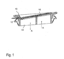
- a venting device 10 is shown, which can be inserted into an opening (not shown) in a support part of a vehicle and has a frame 12.
- the frame 12 has at least one outflow opening 14 which can be closed or opened by a respective non-return valve 16.
- the check valve 16 is in its closed position shown.
- the non-return valve 16 is made of a material that allows the non-return valve 16 is opened by the air flow A from a certain, prevailing in the vehicle interior pressure.
- the check valve 16 may be formed of a soft plastic material and may be made by injection, stamping, stamping or deformation.
- the check valve 16 is shown in different variants.
- the non-return valve 16 is each a separate component and can be attached to the frame 12.
- the non-return valve 16 can be clipped on the frame 12.
- FIGS. 2a to 2f In each case a plurality of recesses 18 are shown, which serve to connect to the frame 12.
- the frame 12 would have corresponding projections (not shown), which can pass through the recesses 18 of the check valve 16 and so can enter into a connection with the same.
- Each non-return valve 16 has a plurality of mutually parallel, in the longitudinal direction L of the check valve 16 extending ribs 20 which reinforce the check valve 16 and prevent the check valve 16 flutters in an outflowing air flow A.
- the ribs 20 are not placed on the check valve 16, but formed by a change in the profile of the check valve 16. That is, the wall thickness of the check valve 16 does not change in the region of the ribs 20.
- the wall thickness is denoted by S and in the FIGS. 3a to 3g shown.
- the ribs 20 may be formed differently, which will be discussed below.
- FIGS. 2a and 2b are the ribs 20 seen in cross-section substantially rectangular, wherein the ribs in FIG. 2a are each rounded off (see also FIGS. 3a, 3b ). Also, the transition of the recesses between the ribs 20 to the region in which the recesses 18 are provided, is in FIG. 2a rounded.
- the in the FIGS. 2e and 2f shown ribs 20 are wavy in cross-section, that is designed as a wave profile, wherein the amplitudes B f , the in FIG. 3f shown ribs 20, slightly larger than the amplitudes B e of in FIG. 3e shown ribs 20 are (see also FIGS. 3e, 3f ).
- the wavelength W e of in FIG. 2e shown in cross section wavy ribs 20 is many times greater than the wavelength W f of in FIG. 2f shown, in cross section wavy ribs 20th
- FIG. 3g the ribs 20 are shown sawtooth in cross-section as seen.
- the ribs 20 are arranged in all figures in the longitudinal direction L, it would be possible to arrange them transversely or obliquely to the longitudinal direction L.
- FIGS. 4a to 4f shown check valves 16 are different from those in the FIGS. 2a to 2f shown check valves 16 only in that the check valves 16 of the FIGS. 4a to 4f are integrally formed with the frame 12.
- the check valves 16 and the frame 12 are formed in the two-component injection molding process, wherein the respective non-return valve 16 is molded onto the frame 12.
- the shape of the ribs 20 of the FIGS. 4a to 4f which serve to reinforce the non-return valve 16, corresponds to the shape of the ribs 20 of FIGS. 2a to 2f , which refers to this.
- FIG 4g a further variant of a check valve 16 with ribs 20 is shown. This differs from those already described in that the ribs 20 seen in the longitudinal direction L end at a distance from an edge 26. By contrast, the ribs 20 of the non-return valves 16 already described extend up to the edge 26 seen in the longitudinal direction L. All embodiments have in common that the non-return valve 16 is formed as a separate component which is attached to the frame 12.
Landscapes
- Engineering & Computer Science (AREA)
- Mechanical Engineering (AREA)
- Physics & Mathematics (AREA)
- Thermal Sciences (AREA)
- General Engineering & Computer Science (AREA)
- Air-Conditioning For Vehicles (AREA)
- Check Valves (AREA)
- Air-Flow Control Members (AREA)
- Building Environments (AREA)
Abstract
Description
Die Erfindung betrifft eine Rückschlagklappe für eine Entlüftungsvorrichtung sowie eine solche Entlüftungsvorrichtung.The invention relates to a non-return valve for a venting device and such a venting device.
Eine Entlüftungsvorrichtung ermöglicht es, die über ein Lüftungssystem dem Fahrzeuginnenraum zugeführte Luft abzuführen. Die Entlüftungsvorrichtung hat einen Rahmen, der wenigstens eine Rückschlagklappe aufnimmt. Wenn keine Luft aus dem Fahrzeuginnenraum ausströmt, liegt die Rückschlagklappe am Rahmen an, so dass ein Eindringen von Feuchtigkeit, Abgas oder Schmutz in den Fahrzeuginnenraum verhindert ist. Es ist bekannt, derartige Entlüftungsvorrichtungen aus zwei Komponenten herzustellen, wobei der Rahmen aus einer härteren Materialkomponente besteht, während die Rückschlagklappe aus einer weicheren Materialkomponente gebildet ist. Wenn im Fahrzeuginnenraum ein höherer Druck herrscht als in der Umgebung des Fahrzeugs, bewegt sich die Rückschlagklappe in eine Stellung, in der die Luft aus dem Fahrzeuginnenraum ausströmen kann. Ab einer bestimmten Luftmenge, die aus dem Fahrzeuginnenraum ausströmt, beginnt die Rückschlagklappe zu flattern, das heißt die Rückschlagklappe wird aufgrund der Luftströmung in Schwingung versetzt. Die in Schwingung versetzte Rückschlagklappe klappert, was störend ist.A ventilation device makes it possible to remove the air supplied via a ventilation system to the vehicle interior. The venting device has a frame which receives at least one non-return valve. If no air flows out of the vehicle interior, the non-return valve is located on the frame, so that penetration of moisture, exhaust gas or dirt into the vehicle interior is prevented. It is known to produce such venting devices from two components, wherein the frame consists of a harder material component, while the non-return valve is formed of a softer material component. If there is a higher pressure in the vehicle interior than in the vicinity of the vehicle, the non-return valve moves to a position in which the air can flow out of the vehicle interior. From a certain amount of air flowing out of the vehicle interior, the non-return valve starts to flutter, that is, the non-return valve is set in vibration due to the air flow. The vibrated check flap rattles, which is disturbing.
Die Aufgabe der Erfindung besteht darin, eine Rückschlagklappe und eine Entlüftungsvorrichtung mit einer solchen Rückschlagklappe bereitzustellen, die mit geringem Aufwand herzustellen ist und sich durch eine gute Funktionalität (Klapperfreiheit usw.) auszeichnet.The object of the invention is to provide a non-return valve and a venting device with such a non-return valve, which can be produced with little effort and is characterized by good functionality (rattle, etc.).
Zu diesem Zweck sieht die Erfindung eine Rückschlagklappe für eine Entlüftungsvorrichtung vor, wobei die Rückschlagklappe mit Rippen versehen ist, die der Verstärkung der Rückschlagklappe dienen, und wobei sich die Wandstärke der Rückschlagklappe im Bereich der Rippen nicht ändert. Die Erfindung beruht auf dem Grundgedanken, die Rückschlagklappe so zu verstärken, dass ein Flattern derselben verhindert ist. Durch die Rippen wird die Rückschlagklappe verstärkt. Selbst bei einer großen ausströmenden Luftmenge, also einer großen Kraft, die auf die Rückschlagklappe einwirkt, flattert die Rückschlagklappe nicht, da die Rückschlagklappe durch die Rippen versteift ist. Es handelt sich bei den Rippen nicht um auf die Rückschlagklappe aufgesetzte Elemente. Vielmehr ist die Wandstärke der Rückschlagklappe im Bereich der Rippen gleichbleibend und die "Rippen" entstehen durch die Änderung des Profils der Rückschlagklappe.For this purpose, the invention provides a non-return valve for a venting device, wherein the non-return valve is provided with ribs, which serve to reinforce the non-return valve, and wherein the wall thickness of the non-return valve in the region of the ribs does not change. The invention is based on the idea to reinforce the non-return valve so that fluttering is the same prevented. The ribs reinforce the non-return flap. Even with a large outflowing air, so a large force acting on the check valve, the check valve does not flutter, since the check valve is stiffened by the ribs. The ribs are not elements placed on the non-return flap. Rather, the wall thickness of the non-return valve in the region of the ribs is constant and the "ribs" caused by the change in the profile of the non-return valve.
Vorzugsweise sind die Rippen in Längsrichtung der Rückschlagklappe vorgesehen. Die Rippen versteifen die Rückschlagklappe in Längsrichtung und verhindern, dass die Rückschlagklappe flattert.Preferably, the ribs are provided in the longitudinal direction of the non-return valve. The ribs stiffen the non-return flap longitudinally and prevent the non-return flap from fluttering.
Genauso gut könnten die Rippen senkrecht zur Längsrichtung oder unter einem beliebigen Winkel zur Längsrichtung angeordnet sein.The ribs could just as well be arranged perpendicular to the longitudinal direction or at any angle to the longitudinal direction.
Die Rippen sind bevorzugt parallel zueinander, weshalb sie die Rückschlagklappe in einer Richtung versteifen.The ribs are preferably parallel to each other, which is why they stiffen the non-return valve in one direction.
Gemäß einer Ausführungsform sind die Rippen im Querschnitt gesehen wellenförmig. Es ist also ein Wellenprofil gebildet, das sich durch seine Stabilität auszeichnet.According to one embodiment, the ribs are wavy in cross section. So it is formed a wave profile, which is characterized by its stability.
Gemäß einer weiteren Ausführungsform sind die Rippen im Querschnitt gesehen trapezförmig, weshalb ein Trapezprofil gebildet ist.According to a further embodiment, the ribs are trapezoidal in cross-section, so that a trapezoidal profile is formed.
Gemäß einer weiteren Ausführungsform sind die Rippen im Querschnitt gesehen rechteckig.According to a further embodiment, the ribs are seen in cross section rectangular.
Auch können die Rippen im Querschnitt gesehen sägezahnartig ausgebildet sein, weshalb ein Sägezahnprofil gebildet ist.Also, the ribs can be seen sawtooth in cross-section, which is why a sawtooth profile is formed.
Die Rückschlagklappe kann gespritzt, geprägt oder gestanzt sein. Die Rückschlagklappe ist aus einem Kunststoff jeglicher Art oder aus Gummi jeglicher Art.The non-return valve can be sprayed, stamped or punched. The non-return flap is made of a plastic of any kind or rubber of any kind.
Ferner betrifft die Erfindung eine Entlüftungsvorrichtung, insbesondere zur Entlüftung eines Fahrzeuginnenraums mit einer Rückschlagklappe der oben genannten Art. Hinsichtlich der Vorteile wird auf die obigen Erläuterungen verwiesen.Furthermore, the invention relates to a ventilation device, in particular for venting a vehicle interior with a non-return valve of the type mentioned above. With regard to the advantages, reference is made to the above explanations.
Vorzugsweise ist ein Rahmen vorgesehen, an dem die Rückschlagklappe angebracht ist. Die Rückschlagklappe ist also ein separates Teil, das getrennt vom Rahmen hergestellt ist und anschließend an diesem angebracht ist. Die Rückschlagklappe kann zum Beispiel am Rahmen angeklipst werden.Preferably, a frame is provided on which the check valve is mounted. The check valve is thus a separate part, which is made separately from the frame and then attached to this. The check valve can be clipped on the frame, for example.
Alternativ ist ein Rahmen vorgesehen, und die Rückschlagklappe ist Teil des Rahmens. Die Rückschlagklappe ist beispielsweise am Rahmen angespritzt. Die Entlüftungsvorrichtung ist also einstückig, wodurch ein Zusammenbau mehrerer einzelner Teile entfällt. Die Entlüftungsvorrichtung ist deshalb kostengünstig.Alternatively, a frame is provided, and the non-return flap is part of the frame. The non-return valve is injection-molded, for example, on the frame. The venting device is thus in one piece, whereby an assembly of several individual parts is eliminated. The venting device is therefore inexpensive.
Weitere Merkmale und Vorteile ergeben sich aus den Unteransprüchen.Further features and advantages emerge from the subclaims.
Die Erfindung wird nachfolgend anhand von Ausführungsformen beschrieben, die in den Zeichnungen dargestellt sind. In den Zeichnungen zeigen:
-
Figur 1 eine Schnittansicht einer erfindungsgemäßen Entlüftungsvorrichtung mit einer erfindungsgemäßen Rückschlagklappe, -
Figuren 2a bis 2f perspektivische Ansichten der Rückschlagklappe vonFigur 1 , wobei die Rückschlagklappe jeweils als separates Bauteil ausgebildet ist und mit Rippen versehen ist, wobei dieFiguren 2a bis 2f verschiedene Varianten der Rückschlagklappe zeigen, -
Figuren 3a bis 3g Querschnitte von Rückschlagklappen, wobei dieFiguren 3a bis 3f die in denFiguren 2a bis 2f gezeigten Varianten der Rückschlagklappe zeigen und dieFigur 3g eine weitere Variante der Rückschlagklappe im Querschnitt gesehen zeigt, und -
Figuren 4a bis 4g perspektivische Ansichten der Rückschlagklappe vonFigur 1 , wobei die Rückschlagklappe jeweils einstückig mit einem Rahmen ausgebildet ist und dieFiguren 4a bis 4g verschiedene Varianten der Rückschlagklappe zeigen.
-
FIG. 1 a sectional view of a ventilation device according to the invention with a check valve according to the invention, -
FIGS. 2a to 2f perspective views of the check valve ofFIG. 1 , wherein the non-return valve is formed in each case as a separate component and is provided with ribs, wherein theFIGS. 2a to 2f show different variants of the non-return valve -
FIGS. 3a to 3g Cross sections of check valves, theFIGS. 3a to 3f in theFIGS. 2a to 2f show variants of the check valve and theFIG. 3g shows a further variant of the check valve seen in cross-section, and -
FIGS. 4a to 4g perspective views of the check valve ofFIG. 1 , wherein the non-return valve is formed in one piece with a frame and theFIGS. 4a to 4g show different variants of the check valve.
In
In den
Jede Rückschlagklappe 16 weist jeweils mehrere parallel zueinander angeordnete, in Längsrichtung L der Rückschlagklappe 16 verlaufende Rippen 20 auf, die die Rückschlagklappe 16 verstärken und verhindern, dass die Rückschlagklappe 16 bei einem ausströmenden Luftstrom A flattert. Die Rippen 20 sind nicht auf die Rückschlagklappe 16 aufgesetzt, sondern durch eine Änderung des Profils der Rückschlagklappe 16 gebildet. D.h. die Wandstärke der Rückschlagklappe 16 ändert sich im Bereich der Rippen 20 nicht. Die Wandstärke ist mit S bezeichnet und in den
In den
Die in den
Die in den
In
Obwohl die Rippen 20 in allen Figuren in Längsrichtung L angeordnet sind, wäre es möglich, diese quer oder schräg zur Längsrichtung L anzuordnen.Although the
Die in den
Die Form der Rippen 20 der
In
Claims (11)
Applications Claiming Priority (1)
| Application Number | Priority Date | Filing Date | Title |
|---|---|---|---|
| DE202007013042U DE202007013042U1 (en) | 2007-09-18 | 2007-09-18 | Non-return flap for a venting device and such a venting device |
Publications (2)
| Publication Number | Publication Date |
|---|---|
| EP2039543A2 true EP2039543A2 (en) | 2009-03-25 |
| EP2039543A3 EP2039543A3 (en) | 2009-12-23 |
Family
ID=38690744
Family Applications (1)
| Application Number | Title | Priority Date | Filing Date |
|---|---|---|---|
| EP08015923A Withdrawn EP2039543A3 (en) | 2007-09-18 | 2008-09-10 | Non-return flap for a ventilation device |
Country Status (6)
| Country | Link |
|---|---|
| US (1) | US20090075580A1 (en) |
| EP (1) | EP2039543A3 (en) |
| JP (1) | JP4922264B2 (en) |
| KR (1) | KR20090029647A (en) |
| CN (1) | CN101391570B (en) |
| DE (1) | DE202007013042U1 (en) |
Families Citing this family (6)
| Publication number | Priority date | Publication date | Assignee | Title |
|---|---|---|---|---|
| KR20110007598A (en) * | 2007-11-28 | 2011-01-24 | 일리노이즈 툴 워크스 인코포레이티드 | Pressure relief assembly |
| DE102010012087B4 (en) * | 2010-03-19 | 2015-04-02 | Trw Automotive Electronics & Components Gmbh | venting device |
| DE102012003258A1 (en) * | 2012-02-21 | 2013-08-22 | Illinois Tool Works Inc. | Return air lock for venting the interior of a motor vehicle |
| DE102013107549B4 (en) * | 2013-07-16 | 2017-11-30 | Maschinenfabrik Reinhausen Gmbh | Load selector for step transformers and carrier arm for a selection of load selector |
| US20160281870A1 (en) * | 2015-03-26 | 2016-09-29 | GM Global Technology Operations LLC | Reverse pressure relief valve to reduce door closing velocity/effort |
| DE102019205684A1 (en) * | 2019-04-18 | 2020-10-22 | Faurecia Interieur Industrie | Fan |
Citations (1)
| Publication number | Priority date | Publication date | Assignee | Title |
|---|---|---|---|---|
| US5105849A (en) | 1991-09-23 | 1992-04-21 | Trw Inc. | Body relief valve flap |
Family Cites Families (16)
| Publication number | Priority date | Publication date | Assignee | Title |
|---|---|---|---|---|
| US3952823A (en) * | 1972-07-10 | 1976-04-27 | Hinderks M V | Vehicle gas extractor |
| JPS5663613A (en) * | 1979-10-29 | 1981-05-30 | Mitsubishi Electric Corp | Operation check circuit of magnetic flux control unit |
| JPS5890815A (en) * | 1981-11-26 | 1983-05-30 | Seiko Instr & Electronics Ltd | Tuning fork type oscillator |
| DE4002052C2 (en) * | 1990-01-24 | 1994-03-24 | United Carr Gmbh Trw | Return valve |
| DE4023190C2 (en) * | 1990-07-20 | 1995-11-02 | United Carr Gmbh Trw | Return valve |
| FR2704184B1 (en) * | 1993-04-23 | 1995-06-23 | Valeo Thermique Habitacle | SHUTTER FOR HEATING OR AIR CONDITIONING APPARATUS. |
| US5355910A (en) * | 1993-10-13 | 1994-10-18 | Trw Inc. | Dual component flap |
| DE19629115C2 (en) * | 1996-07-19 | 1999-08-19 | Draebing Kg Wegu | Process for the production of a forced ventilation for motor vehicles and a forced ventilation for motor vehicles |
| US5842503A (en) * | 1996-08-16 | 1998-12-01 | The Excello Specialty Company | Integrally formed air flow valve |
| US5727999A (en) * | 1997-02-28 | 1998-03-17 | Trw Inc. | Vehicle ventilation valve |
| JPH10272918A (en) * | 1997-03-31 | 1998-10-13 | Nippon Plast Co Ltd | Vehicular ventilator |
| US6026852A (en) * | 1998-06-08 | 2000-02-22 | Blue Water Plastics, Inc. | Pressure relief valve and method of manufacturing the same |
| US6210266B1 (en) * | 1999-03-15 | 2001-04-03 | Sarnamotive Blue Water, Inc. | Pressure relief valve and method of manufacturing the same |
| JP2002036861A (en) * | 2000-07-25 | 2002-02-06 | Inoac Corp | Ventilation duct |
| CN2435596Y (en) * | 2000-08-03 | 2001-06-20 | 黄钊仁 | One-way airflow leaf-valve |
| DE202006002771U1 (en) * | 2006-02-22 | 2006-04-27 | Dr. Schneider Engineering Gmbh | Flap for being inserted into ventilation or heating duct at vehicle, comprising corrugated cross section |
-
2007
- 2007-09-18 DE DE202007013042U patent/DE202007013042U1/en not_active Expired - Lifetime
-
2008
- 2008-08-18 JP JP2008209525A patent/JP4922264B2/en not_active Expired - Fee Related
- 2008-08-28 US US12/229,974 patent/US20090075580A1/en not_active Abandoned
- 2008-09-10 EP EP08015923A patent/EP2039543A3/en not_active Withdrawn
- 2008-09-11 KR KR1020080089697A patent/KR20090029647A/en not_active Application Discontinuation
- 2008-09-17 CN CN2008101492385A patent/CN101391570B/en not_active Expired - Fee Related
Patent Citations (1)
| Publication number | Priority date | Publication date | Assignee | Title |
|---|---|---|---|---|
| US5105849A (en) | 1991-09-23 | 1992-04-21 | Trw Inc. | Body relief valve flap |
Also Published As
| Publication number | Publication date |
|---|---|
| CN101391570B (en) | 2012-02-29 |
| DE202007013042U1 (en) | 2007-11-15 |
| JP2009073477A (en) | 2009-04-09 |
| EP2039543A3 (en) | 2009-12-23 |
| JP4922264B2 (en) | 2012-04-25 |
| CN101391570A (en) | 2009-03-25 |
| KR20090029647A (en) | 2009-03-23 |
| US20090075580A1 (en) | 2009-03-19 |
Similar Documents
| Publication | Publication Date | Title |
|---|---|---|
| EP2050600B1 (en) | Air venting device | |
| DE102006056868B4 (en) | Return air lock for venting the interior of a motor vehicle | |
| DE69414512T2 (en) | Flap type pressure relief valve and method for its manufacture | |
| EP1985480B1 (en) | Ventilation flap | |
| DE19820699C1 (en) | Guide link for sliding lids on sunroof constructions for motor vehicles | |
| EP3103665B1 (en) | Profile strip, system and method for production of a profile strip | |
| EP2039543A2 (en) | Non-return flap for a ventilation device | |
| DE102012003258A1 (en) | Return air lock for venting the interior of a motor vehicle | |
| DE102011102158A1 (en) | Roof structure of a motor vehicle, as well as roof module | |
| DE102013008937A1 (en) | Pillar trim structure | |
| DE112014000458B4 (en) | Front body structure of a motor vehicle | |
| DE112016005444T5 (en) | Liquid dissipating pressure relief arrangement | |
| AT408480B (en) | THROTTLE CHECK VALVE AND METHOD FOR THE PRODUCTION THEREOF | |
| EP1527917A1 (en) | Non return exhaust valve for a vehicle venting system | |
| DE102016117057A1 (en) | Door frame of a motor vehicle | |
| EP1247672B2 (en) | Roof unit for vehicle | |
| DE19845746C2 (en) | Valve, in particular ventilation valve for the interior of a motor vehicle | |
| DE102006025647B4 (en) | airbag cover | |
| WO2022111760A1 (en) | Profiled strip with a water-discharging element | |
| EP1134105B1 (en) | Sliding screen for vehicle roof with anti sqeezing reinforced screen panel | |
| DE102017009422A1 (en) | Outlet element for a ventilation device in the interior of a motor vehicle | |
| DE102009007407A1 (en) | Upper loop-around fitting or attachment fitting height adjustment device for shoulder belt of safety seat belt system in vehicle, has metal plates with ends that form detent, where ends are directed to outer edge of detent recess | |
| DE8128937U1 (en) | DEVICE FITTING FOR A SAFETY BELT | |
| DE102004057899B4 (en) | Vehicle flap arrangement for a motor vehicle | |
| DE202009017015U1 (en) | Absorber element for a motor vehicle |
Legal Events
| Date | Code | Title | Description |
|---|---|---|---|
| PUAI | Public reference made under article 153(3) epc to a published international application that has entered the european phase |
Free format text: ORIGINAL CODE: 0009012 |
|
| AK | Designated contracting states |
Kind code of ref document: A2 Designated state(s): AT BE BG CH CY CZ DE DK EE ES FI FR GB GR HR HU IE IS IT LI LT LU LV MC MT NL NO PL PT RO SE SI SK TR |
|
| AX | Request for extension of the european patent |
Extension state: AL BA MK RS |
|
| PUAL | Search report despatched |
Free format text: ORIGINAL CODE: 0009013 |
|
| AK | Designated contracting states |
Kind code of ref document: A3 Designated state(s): AT BE BG CH CY CZ DE DK EE ES FI FR GB GR HR HU IE IS IT LI LT LU LV MC MT NL NO PL PT RO SE SI SK TR |
|
| AX | Request for extension of the european patent |
Extension state: AL BA MK RS |
|
| 17P | Request for examination filed |
Effective date: 20100622 |
|
| 17Q | First examination report despatched |
Effective date: 20100716 |
|
| AKX | Designation fees paid |
Designated state(s): AT BE BG CH CY CZ DE DK EE ES FI FR GB GR HR HU IE IS IT LI LT LU LV MC MT NL NO PL PT RO SE SI SK TR |
|
| STAA | Information on the status of an ep patent application or granted ep patent |
Free format text: STATUS: THE APPLICATION IS DEEMED TO BE WITHDRAWN |
|
| 18D | Application deemed to be withdrawn |
Effective date: 20130403 |