EP2038860B1 - Automated site security, monitoring and access control system - Google Patents
Automated site security, monitoring and access control system Download PDFInfo
- Publication number
- EP2038860B1 EP2038860B1 EP07870992.0A EP07870992A EP2038860B1 EP 2038860 B1 EP2038860 B1 EP 2038860B1 EP 07870992 A EP07870992 A EP 07870992A EP 2038860 B1 EP2038860 B1 EP 2038860B1
- Authority
- EP
- European Patent Office
- Prior art keywords
- vehicle
- area
- license plate
- database
- vehicles
- Prior art date
- Legal status (The legal status is an assumption and is not a legal conclusion. Google has not performed a legal analysis and makes no representation as to the accuracy of the status listed.)
- Active
Links
- 238000012544 monitoring process Methods 0.000 title claims description 46
- 238000012545 processing Methods 0.000 claims description 45
- 238000004891 communication Methods 0.000 claims description 28
- 238000000034 method Methods 0.000 claims description 23
- 230000004888 barrier function Effects 0.000 claims description 22
- 230000008569 process Effects 0.000 claims description 10
- 238000003384 imaging method Methods 0.000 claims description 8
- 230000000007 visual effect Effects 0.000 claims description 4
- 238000013475 authorization Methods 0.000 claims description 2
- 238000010586 diagram Methods 0.000 description 12
- 230000009471 action Effects 0.000 description 5
- 238000005516 engineering process Methods 0.000 description 4
- 238000001514 detection method Methods 0.000 description 3
- 238000005286 illumination Methods 0.000 description 3
- 238000012986 modification Methods 0.000 description 2
- 230000004048 modification Effects 0.000 description 2
- 238000011160 research Methods 0.000 description 2
- 230000001960 triggered effect Effects 0.000 description 2
- 230000003213 activating effect Effects 0.000 description 1
- 230000004913 activation Effects 0.000 description 1
- 238000013459 approach Methods 0.000 description 1
- 230000007123 defense Effects 0.000 description 1
- 239000000284 extract Substances 0.000 description 1
- 239000000835 fiber Substances 0.000 description 1
- 230000010365 information processing Effects 0.000 description 1
- 238000009434 installation Methods 0.000 description 1
- 238000012806 monitoring device Methods 0.000 description 1
- 230000003287 optical effect Effects 0.000 description 1
- 230000004044 response Effects 0.000 description 1
Images


Classifications
-
- G—PHYSICS
- G08—SIGNALLING
- G08G—TRAFFIC CONTROL SYSTEMS
- G08G1/00—Traffic control systems for road vehicles
- G08G1/01—Detecting movement of traffic to be counted or controlled
- G08G1/017—Detecting movement of traffic to be counted or controlled identifying vehicles
- G08G1/0175—Detecting movement of traffic to be counted or controlled identifying vehicles by photographing vehicles, e.g. when violating traffic rules
-
- G—PHYSICS
- G06—COMPUTING; CALCULATING OR COUNTING
- G06V—IMAGE OR VIDEO RECOGNITION OR UNDERSTANDING
- G06V20/00—Scenes; Scene-specific elements
- G06V20/50—Context or environment of the image
- G06V20/52—Surveillance or monitoring of activities, e.g. for recognising suspicious objects
-
- G—PHYSICS
- G08—SIGNALLING
- G08G—TRAFFIC CONTROL SYSTEMS
- G08G1/00—Traffic control systems for road vehicles
- G08G1/065—Traffic control systems for road vehicles by counting the vehicles in a section of the road or in a parking area, i.e. comparing incoming count with outgoing count
-
- G—PHYSICS
- G08—SIGNALLING
- G08G—TRAFFIC CONTROL SYSTEMS
- G08G1/00—Traffic control systems for road vehicles
- G08G1/20—Monitoring the location of vehicles belonging to a group, e.g. fleet of vehicles, countable or determined number of vehicles
- G08G1/207—Monitoring the location of vehicles belonging to a group, e.g. fleet of vehicles, countable or determined number of vehicles with respect to certain areas, e.g. forbidden or allowed areas with possible alerting when inside or outside boundaries
Definitions
- This invention relates to security systems. More particularly, the invention relates to the use of cameras and other monitoring devices to provide for automated monitoring and access control of vehicular traffic within secured areas.
- a preferred embodiment of the invention includes a plurality of cameras, such as infrared-sensitive cameras, for capturing images of the license plates of vehicles traveling into the facility, within the facility, and even exiting the facility.
- the apparatus includes a video image processing system, such as a software engine running on a computer processor, for detecting and extracting a vehicle license plate number (LPN), or other such identifying characters, within the captured image of the license plate. Based at least in part on the location of the camera that captured the LPN, the processor stores the LPN with a time-stamp and other pertinent information in one or more databases.
- LPN vehicle license plate number
- These databases can include but are not limited to, a site LPN database, an in-transit LPN database, an employee database, an expected visitor database, a blacklist database, also known as "license plates of interest", a loiterer database, a speeder database, a high-security database, a high-security parking lot database, a normal security parking lot database, and a visitor parking lot database.
- the processor controls the activation of various physical barriers to allow ingress to and egress from defined areas throughout the site.
- the processor controls information posted on various terminals in the site, such as a Security Portal and a parking lot pay booth, and on Variable Messaging Signs (VMS) at various locations within the site.
- VMS Variable Messaging Signs
- the video image processing is performed on processors, such as in personal computers or dedicated image processors networked throughout the site.
- the video image processing is performed on a single processor that serves all of the cameras in the site.
- the cameras can communicate with the video image processing system and/or the main processor by way of a communication network, such as a local area network (LAN), modem, RF modulator, wide area network (WAN), or global network such as the Internet.
- a communication network such as a local area network (LAN), modem, RF modulator, wide area network (WAN), or global network such as the Internet.
- the invention provides an automated system for performing various site security monitoring and site access-control actions based upon the different event types as defined by the user.
- the invention is an event-driven system activated by a camera reading a license plate and/or a temporary passive tag issued and controlled by the facility. The reading of the license plate is triggered either by the plate being detected within the camera video or by an optional trigger such as a light curtain or embedded loop. Events are processed to update the underlying LPN data held in various databases (or in various tables within a single database). Separate databases are maintained such as the site as a whole, for an employee parking lot, for a high-security parking lot, and for a visitor parking lot.
- the LPN information for the various facilities within the site may be stored in a single database.
- a loiterer database and speeder database may be created for the respective event types.
- the employee parking lot is split across two levels with respective databases for level I and level 2, and the number of unoccupied parking spaces in each level is displayed on variable message signs.
- all vehicles entering the site are recorded on the site database.
- Vehicles in the employee parking lot, high-security parking lot or visitor parking lot are entered in the respective inventory databases.
- Vehicles which are not in these databases, but which are in the site database, are in transit on the site.
- One preferred embodiment of the invention provides a system for monitoring and controlling access of vehicles according to claim 1.
- the vehicle databases are for storing characters, such as license plate numbers, associated with vehicles that are within the secure facility and vehicles having prior authorization to enter restricted areas within the secure facility.
- One or more of the processors receive the characters identified by the video image processing system and access the vehicle databases to determine whether the identified characters correspond to characters stored in the vehicle databases. Depending on whether or not the identified characters correspond to characters stored in the databases, the system may initiate various actions, such as raising or lowering barrier gates, updating information in the databases, activating message signs in the secure facility to communicate with vehicle drivers, and alerting security personnel regarding vehicles that are speeding or loitering within the secure facility.
- the invention provides a method for monitoring and controlling access of vehicles according to claim 15.
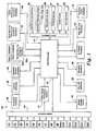
- Fig. 1 depicts a functional block diagram of a site security, monitoring, and access control apparatus according to a preferred embodiment of the invention
- Fig. 2 depicts components of the site security, monitoring, and access control apparatus according to a preferred embodiment of the invention
- Figs. 3-10 depict steps in event-driven monitoring and access control processes according to preferred embodiments of the invention.
- Fig. 11 depicts a functional block diagram of a site security, monitoring, and access control apparatus according to an alternative embodiment of the invention.
- Fig. 12 depicts a mobile monitoring station according to a preferred embodiment of the invention.
- Figs. 1 and 2 Depicted in Figs. 1 and 2 is an automated system 10 for controlling access to a secure site, such as a military base or high-security research facility, and for monitoring location of vehicles traveling within the site.
- the system 10 includes a number of monitoring cameras, such as cameras C1-C14 depicted in Fig.2 for capturing images of license plates, or of a passive tag issued by the facility, of vehicles entering, traveling within and exiting the site.
- the cameras C1, C3 and C5-C14 include an integrated infrared emitter for providing infrared illumination to a retro reflective surface on the license plate, such as cameras manufactured by PIPS Technology, Inc. of Knoxville, TN under model numbers P356, P366, or P362.
- the cameras C1, C3 and C5-C14 will covertly capture a license plate image at night or in the daylight. Where a vehicle does not display a license plate, an alternative passive tag will be issued by the facility and read in the same manner.
- the cameras C2 and C4 are preferably standard visible-light color video cameras.
- the cameras C1, C3 and C5-C14 of the preferred embodiment are infrared cameras
- the system 10 described herein may also incorporate visible light cameras with appropriate illumination if necessary for license plate image capture.
- the invention is not limited to any particular type of camera or imaging wavelength.
- some or all of the cameras C1-C14 are connected to a video image processing system 12 via a communication network 14.
- the network 14 may be hard-wired, wireless, or fiber optic.
- the video image processing system 12 receives video images captured by the cameras C1, C3 and C5-C14, such as images of vehicle license plates, and processes those images to recognize characters within the images, such as the vehicle license plate number (LPN) on the license plate.
- the video image processing system 12 may include a realtime hardware license plate detector such as described in United Kingdom patent number GB 2,332,322 entitled “Detection of Vehicle License Plates,” or a software-based system such as used in the PIPS Technology PC-based "Autoplate” software.
- the video image processing system 12 provides the LPN to a main processor 16 that performs several functions based on the LPN, as described in more detail hereinafter.
- the video image processing system 12 is a central system that receives and processes video information from the multiple distributed video cameras C1, C3 and C5-C14.
- the video information processing could be distributed rather than central.
- a remote processor could handle the input from the cameras.
- each of the distributed video image processing systems 12a-12f extracts the LPN from the license plate image captured by the local camera or cameras, and communicates the LPN, with a time-stamp and other pertinent information to the main processor 16 via the communication network 14.
- the barriers and VMS's are preferably controlled by the remote processors 12a-12f, such as the processors provided in the model P357 Processor manufactured by PIPS Technology Inc. While using remote processing to control such items as physical barriers, the system 10 could still refer to a central database or databases for the status of the vehicle.
- the communications infrastructure in such a distributed system requires less bandwidth because less video information is being transmitted over the communication network 14.
- the examples of system operation described hereinafter may be carried out using the central video image processing system 12 ( Fig. 1 ) or the distributed video image processing system, 12a-12f ( Fig. 11 ).
- the main processor 16 has access to several databases, wherein LPNs are cross-referenced with other pertinent information.
- the Site LPN Database 18 cross-references the LPNs of each and every vehicle that is within the site with the name of the vehicle operator, an image of the vehicle operator, the zones within the site to which the vehicle may have access, the time of the vehicle entry into the site, and other pertinent information.
- Other of the databases are described hereinafter. These databases are preferably stored on mass storage devices, such as magnetic or optical disks, directly interfaced to and co-located with the main processor 16. Alternatively, the databases may reside on one or more storage devices located remotely from the main processor 16, and accessed by the main processor 16 through the communication network 14.
- the main processor 16 is connected to one or more barrier control interfaces 20 through the communication network 14. Based on signals provided by the main processor 16, the barrier control interfaces 20 control barriers within the site 10 that may be opened to allow vehicles to proceed into or out of particular zones within the site 10, or closed to impede vehicle movement from one zone to another. Within the site 10 depicted in Fig. 2 , there are five barriers B1-B5.
- the main processor 16 is also connected via the communication network 14 to variable messaging signs (VMS) 22, 24, 26, such as signs manufactured by Addco and other such VMS suppliers.
- VMS variable messaging signs
- the message displayed on these signs may be changed based upon signals provided by the main processor 16.
- Exemplary uses of the signs 22, 24, 26 are described in more detail below.
- remote communication terminals 28 are Also connected to the main processor 16 via the communication network 14 .
- the communication terminals 28 are used to communicate information from the main processor 16 to security and other personnel, such as in the Security Portal or Pay Booth.
- the communication terminals 28 are personal computers.
- a physical presence trigger signal can be connected locally to the local Video Image Processor 12a-12f, rather than having to be communicated to the central processor.
- the presence of a vehicle is sensed by any one of the cameras C1, C3 and C5-C14, such as by detecting a license plate within an image of the vehicle.
- the physical presence of a vehicle is sensed by a vehicle presence trigger or sensor, such as a magnetic sensor embedded in the pavement or an infrared sensor.
- a vehicle presence trigger or sensor such as a magnetic sensor embedded in the pavement or an infrared sensor.
- physical presence sensors are used in the highest security applications, such as in detecting a vehicle approaching the entrance gate.
- Video triggering alone may be used in lower security applications, such as speed detection.
- either or both types of triggering may be used to initiate a sequence of events as described below, and that the invention is not limited to any particular type of event triggering.
- the subsequent processing steps preferably depend upon the location of the vehicle in the site.
- the location of the vehicle in the site is associated with a particular camera positioned at the location.
- the processing steps are determined by identification number of the camera at the location where the vehicle is detected.
- the camera captures an image of the vehicle's license plate (step 102).
- a time-stamp, camera identifier and other pertinent information are associated with the image of the plate (step 104).
- the time-stamp is information indicating the time and date that the image of the vehicle license plate was captured.
- the camera identifier is information indicating which camera in the system 10 captured the image of the license plate.
- the camera identifier may be a TCP/IP address of the camera on the communication network 14.
- the cameras are identified by the reference numbers C1-C14.
- the image of the plate is transferred to the image processing system 12, such as via the communication network 14, and the image processing system 12 recognizes the characters of the LPN in the image of the plate using character recognition techniques, such as employed in products such as the PIPS Technology Inc. model P357 dedicated Automated License Plate Recognition (ALPR) processor or its "Autoplate” PC based ALPR software. (step 106).
- the LPN is then associated with the time-stamp, plate image, and other pertinent information.
- cameras C4 and C2 capture images of the driver and the front of the vehicle, respectively (step 142).
- the images of the vehicle license plate (from camera C1), the driver (from camera C4), and the vehicle overview (from camera C2) are then associated with the LPN (step 144).
- the system 10 may include an employee LPN database 30 in which the LPNs of all vehicles registered to the site employees are associated with other employee information, such as the employee name, identification number, security clearance level, zones within the site to which the employee may have access and employee photograph.
- the embodiment of the system may include an expected visitor database 32 in which the LPNs of all vehicles registered to expected visitors are associated with other visitor information, such as the visitor's name, the date of the expected visit, the name of the employee to be visited, and the zone(s) within the site to which the visitor may have access.
- the database entries can provide a full historic record of all significant vehicle movements within the site, so that in the event of an 'incident,' the historic record, including the captured images, can be searched in order to provide evidence of the perpetrator.
- the system not only provides enhanced security measures, it also can be used as an evidentiary tool enabling historical data to be accessed. As an example, the status of a 'visitor' may not have been correctly identified at the Security Portal.
- the vehicle will be authorized for admittance to the site.
- the LPN and a time-stamp are added to the site LPN database 18 (step 150) and to an In-Transit LPN database 19.
- Any additional information from the employee LPN database 30 or the expected visitor database 32 associated with the LPN is preferably stored in the site's LPN database 18.
- images captured by the cameras C4 and C2 are also stored at this time, such as in an image storage device 34, and are associated with the LPN or other identifying information (step 152).
- the barrier B1 is opened in response to a signal communicated from the main processor 16 to the barrier control interface 20 via the communication network 14 (step 154). In this manner, no human intervention is required to raise the barrier B1 and allow entry of the vehicle into the site, if the vehicle's LPN is in the employee LPN database 30 or the expected visitor database 32.
- the barrier B1 may be opened by a manual control located in the Security Portal.
- a "blacklist” database 36 is accessed to determine whether the LPN is stored therein (step 156).
- the "blacklist” database 36 preferably contains the LPNs associated with vehicles that are to be denied access to the site for any reason determined by the site facility management.
- the "blacklist” database 36 may include the LPNs of vehicles used previously by persons who have violated security restrictions on the site or by persons known to be wanted by law enforcement officials and/or known or suspected terrorists. This may include both national, international and domestic suspects.
- step 160 security personnel are automatically notified.
- the main processor 16 provides this notification by sending a configurable alert message and/or tone to the Security Portal that will be displayed on a display device 28a in the Security Portal. Additionally, an alert message may be e-mailed to security officials, on-site or off-site, who are authorized to be informed or warned that a "blacklisted" vehicle was attempting to enter the site.
- step 158 security personnel in the Security Portal are notified that personal intervention is required (step 162). For example, security personnel may question the driver of the vehicle regarding his or her destination and business on the site, and the employee to be contacted to confirm whether the stated business is legitimate. If the vehicle is to be admitted (step 164), processing preferably continues at step 150. If the vehicle is not to be admitted (step 164), processing preferably continues at step 160.
- the LPN, time-stamp, and camera identifier are added to the in-transit LPN database 19 (step 132) to be accessed in subsequent processing.
- step 112 processing continues at point B in the flow diagram of Fig. 5 .
- the LPN, time-stamp and camera identifier are added to the in-transit LPN database 19 (step 166).
- the time-stamps associated with cameras C9 and C14 are retrieved from the in-transit LPN database 19 for the current LPN (step 168), and the time taken for the vehicle to travel from camera C14 to C9 is calculated (step 170). If the vehicle travel time between cameras C14 and C9 is greater than the facility's predetermined maximum time (step 172), then the vehicle is designated as a "loiterer".
- the vehicle LPN and time-stamp are added to a loiterer database 38 (step 174).
- security personnel are automatically notified when a LPN is added to the loiterer database 38 so that the security personnel may take appropriate action at the appropriate time.
- the LPN, time-stamp, and camera identifier are added to the in-transit LPN database 19.
- a counter or timer begins to measure elapsed time. If a maximum predetermined time elapses before the vehicle is detected at camera C9, the vehicle LPN and time-stamp are added to the "loiterer" database 38 and security personnel are automatically notified.
- the vehicle travel time between cameras C14 and C9 is less than facility's predetermined minimum time (step 176)
- the vehicle is designated as a "speeding violator". This may occur, for example, if the vehicle exceeds the posted speed limit on the section of road between the two cameras.
- the vehicle LPN and time-stamp are added to a speeder database 40 (step 178).
- security personnel are automatically notified when a LPN is added to the speeder database 40 so that the security personnel may take appropriate action at the appropriate time.
- the main processor 16 may generate a notification that is communicated through the communication network 14 to the VMS 22 to notify the operator of the vehicle that the vehicle had been in violation of the posted speed limit.
- the system 10 of the preferred embodiment activates the VMS 22 to provide pertinent information to the driver of the vehicle (step 182). This is preferably accomplished by first accessing the site LPN database 18 to determine the destination of the vehicle within the site (step 180). The VMS 22a is then activated to display a message, such as information regarding the vehicle's destination. For example, if the information accessed from the site LPN database indicates that the vehicle is destined for the visitor parking lot, the VMS 22a may display directions to that destination.
- the main processor 16 accesses a high-security database 42 (step 184), and a determination is made whether the detected LPN is listed therein in association with an employee or visitor having a high-security clearance (step 186). If the detected LPN is in the high-security database 42 (step 186), a signal is provided via the barrier control interface 20 to raise the barrier B4 or a like device to allow the vehicle to proceed into the high security parking lot. Preferably, the vehicle's LPN and associated time-stamp are then added to a high security parking lot inventory database 44. If the detected LPN is not in the high-security database 42 (step 186), the vehicle is denied entry into the high security parking lot and security personnel are automatically notified (step 188).
- the LPN is removed from the high security parking lot inventory database 44 (step 136), and the LPN, time-stamp and camera identifier (such as C5) are added to the in-transit LPN database 19 (step 138). This process is repeated so long as the vehicle remains on the monitored facility.
- the detected LPN may be associated with a parking ticket number (step 194), such as the next parking ticket number in a sequence of numbers, and the image of the vehicle license plate captured by the camera C10 is stored in association with the LPN and ticket number (step 195).
- a parking ticket dispenser 24 is then activated to dispense a parking ticket having printed thereon the parking ticket number associated with the LPN (step 196).
- the barrier B3 is raised (step 198), and the LPN, time-stamp, and ticket number are added to the visitor parking lot inventory database 48 (step 200).
- the processes mentioned herein generally relate to those facilities that utilize automated ticket dispensers as part of their parking control.
- the preferred embodiment of the invention includes a ticket reader 26 for receiving the parking ticket from the vehicle operator and for reading the encoded parking ticket number from the parking ticket (step 202).
- the ticket reader 26 comprises a bar-code reader. After the ticket number has been read from the parking ticket, the visitor parking lot inventory database 48 is accessed to retrieve the LPN that was associated with the ticket number at the time the ticket was dispensed (step 204).
- a parking fee is calculated based upon the duration of stay as computed by the system. The calculated fee becomes due prior to exit (step 208).
- the LPN and time-stamp are then added to the in-transit LPN database 19 (step 210), and the barrier B2 is raised to allow the vehicle to exit the visitor parking lot (step 211).
- the system 10 initiates a process to resolve the mismatch.
- the image of the vehicle license plate associated with the ticket number read by the ticket reader 26 is retrieved and displayed at the pay booth terminal 28b (step 212). Also displayed at the pay booth terminal 28b is the image of the vehicle license plate captured by the camera C11 (step 212).
- the booth attendant will visually compare the two images to determine a match (step 212).
- the pay booth attendant manually corrects the LPN in the visitor parking lot inventory database 48 to match the LPN shown in the images (step 216). This manual intervention would generally only occur in exceptional circumstances.
- the LPN and time-stamp are then preferably added to the in-transit LPN database 19 (step 210), and the barrier B2 or like device is actuated to allow the vehicle to exit the visitor parking lot (step 211).
- the parking supervisor could be notified, preferably automatically such as by email, that personal intervention is necessary (step 218). This situation occurs, for example, if someone attempts to exit the parking lot using a ticket that was dispensed to the driver of another vehicle.
- the main processor 16 accesses the employee database 30 (step 220), and a determination is made whether the detected LPN is listed therein (step 222). If the detected LPN is in the employee database 30 (step 222), the vehicle's LPN and associated time stamp are then preferably added to a normal-security parking lot first level inventory database 50a (step 224), and removed from the in-transit LPN database 19 (step 226). A signal is provided via the barrier control interface 20 to actuate the barrier B5 or like device to allow the vehicle to proceed into the normal-security parking lot (step 228).
- a value indicating the number of remaining unoccupied parking spaces in level one of the parking lot is decremented (step 230).
- this value is a record stored in the normal-security parking lot first level inventory database 50a.
- the number of unoccupied parking spaces in levels one and two of the normal-security parking lot are then preferably displayed on the VMS 22b at the entrance to level one of the normal-security parking lot, and on the VMS 22c at the entrance to level two of the normal-security parking lot (step 232). This process would apply regardless of the number of levels available in each parking lot.
- the vehicle is denied entry into the normal-security parking lot by the use of a barrier or like device and an automatic message is displayed on the VMS 22b to direct the vehicle to the authorized parking lot (step 234).
- Security personnel can be automatically notified that an unauthorized vehicle has attempted entry into an unauthorized parking lot.
- the vehicle's LPN and associated time stamp are preferably removed from the normal-security parking lot first level inventory database 50a (step 236), and added to the normal-security parking lot second level inventory database 50b (step 238).
- the value indicating the number of unoccupied parking spaces in level one of the parking lot is incremented (step 240), and a value indicating the number of unoccupied parking spaces in level two of the parking lot is decremented (step 242).
- the value indicating the number of unoccupied parking spaces in level two of the parking lot is a record stored in the normal-security parking lot second level inventory database 50b.
- the number of unoccupied parking spaces in levels one and two of the normal-security parking lot are then preferably displayed on the VMS 22b at the entrance to level one of the normal-security parking lot, and on the VMS 22c at the entrance to level two of the normal-security parking lot (step 244).
- the vehicle's LPN and associated time stamp are preferably removed from the normal-security parking lot second level inventory database 50b (step 246), and added to the normal-security parking lot first level inventory database 50a (step 248).
- the value indicating the number of unoccupied parking spaces in level two of the parking lot is incremented (step 250), and a value indicating the number of unoccupied parking spaces in level one of the parking lot is decremented (step 252).
- the number of unoccupied parking spaces in levels one and two of the normal-security parking lots are then preferably displayed on the VMS's 22b and 22c (step 244).
- the vehicle's LPN and associated time stamp are preferably removed from the normal-security parking lot first level inventory database 50a (step 254), and added to the in-transit LPN database 19 (step 256).
- the value indicating the number of unoccupied parking spaces in level one of the parking lot is incremented (step 258) and the number of unoccupied parking spaces in levels one and two of the normal-security parking lot are displayed on the VMS 22b and 22c (step 244).
- the vehicle's LPN is preferably removed from the site LPN database 18 and the in-transit LPN database 19 (step 140).
- Fig. 12 depicts a preferred embodiment of the invention wherein the camera C14 and the video image processing system 12f are components of a mobile monitoring station 60.
- the mobile station 60 also includes a location determination unit 62, such as a GPS receiver, for providing location coordinates to the video image processing system 60.
- the communication network 14 provides wireless communication between the mobile station 60 and the main processor 16.
- wireless communication may be implemented via a terrestrial radio frequency (RF) link, such as a microwave or a Wi-Fi (IEEE 802.11) link, or via a satellite link.
- RF radio frequency
- the camera C14, video image processing system 12f and location determination unit 62 of the mobile station 60 are mounted on or installed in a trailer that may be hauled to any desired location within the facility.
- the components of the mobile station 60 may be permanently or semi-permanently installed in a vehicle. These trailer-mounted or vehicle mounted embodiments allow for rapid deployment of a mobile station 60 in emergency situations and temporary deployments as needed.
- multiple mobile stations 60 are deployed at various locations throughout the secure facility.
- a pair of mobile stations 60 is particularly applicable in detecting speed limit violators and loiterers as discussed above.
- the camera C9, video image processing system 12e and variable messaging sign 22a may also be components of a mobile monitoring station 60 having a GPS receiver 62.
- location coordinates (such as determined by the GPS unit 62) are transmitted to the main processor 16 along with the LPN, time-stamp and camera identifier.
- the location coordinates may be stored in one or more of the databases along with the other pertinent information. For example, location coordinates may be added to the in-transit database 19 at step 132 in Fig. 3 and at step 166 in Fig. 5 , to the loiterer database 38 at step 174 in Fig. 5 , and to the speeding violator database 40 at step 178 in Fig. 5 .
Description
- This invention relates to security systems. More particularly, the invention relates to the use of cameras and other monitoring devices to provide for automated monitoring and access control of vehicular traffic within secured areas.
- In today's world, there is an ever-growing concern about limiting and controlling access to areas containing highly-sensitive information and personnel, such as Department of Defense and Department of Energy facilities, research laboratories, airports and military installations. There is also concern about protecting the security of students, such as on high school or university campuses. In the private sector, business operations that occupy large areas, such as hotels and resorts, cruise liner terminals, airports, country clubs, container ports, and large multi-level parking facilities, have a need for monitoring and controlling vehicular access to various zones within the area occupied by the business. Security and vehicular access control may also be mandated for private gated communities.
- Prior security systems designed to monitor and control access to such facilities have been lacking in many respects. What is required, therefore, is an improved integrated security system for automatically controlling access to secure areas, for monitoring the movements of vehicles that have been granted access to the secure areas and for providing information in real time to both manned and unmanned security locations regarding such access and movements.
- An example monitoring system is shown in
US 6,340,935 , which is understood to be the closest prior art. - The above requirements and others are met by an apparatus for automatically monitoring and controlling the ingress and egress of vehicles to and from a facility and various areas within. A preferred embodiment of the invention includes a plurality of cameras, such as infrared-sensitive cameras, for capturing images of the license plates of vehicles traveling into the facility, within the facility, and even exiting the facility. The apparatus includes a video image processing system, such as a software engine running on a computer processor, for detecting and extracting a vehicle license plate number (LPN), or other such identifying characters, within the captured image of the license plate. Based at least in part on the location of the camera that captured the LPN, the processor stores the LPN with a time-stamp and other pertinent information in one or more databases. These databases can include but are not limited to, a site LPN database, an in-transit LPN database, an employee database, an expected visitor database, a blacklist database, also known as "license plates of interest", a loiterer database, a speeder database, a high-security database, a high-security parking lot database, a normal security parking lot database, and a visitor parking lot database. Depending on the location of the camera that captured the LPN and whether the vehicle's LPN is listed in one or more of the above-listed databases, the processor controls the activation of various physical barriers to allow ingress to and egress from defined areas throughout the site. The processor controls information posted on various terminals in the site, such as a Security Portal and a parking lot pay booth, and on Variable Messaging Signs (VMS) at various locations within the site.
- In one preferred embodiment, the video image processing is performed on processors, such as in personal computers or dedicated image processors networked throughout the site. In an alternative embodiment, the video image processing is performed on a single processor that serves all of the cameras in the site.
- The cameras can communicate with the video image processing system and/or the main processor by way of a communication network, such as a local area network (LAN), modem, RF modulator, wide area network (WAN), or global network such as the Internet.
- The invention provides an automated system for performing various site security monitoring and site access-control actions based upon the different event types as defined by the user. The invention is an event-driven system activated by a camera reading a license plate and/or a temporary passive tag issued and controlled by the facility. The reading of the license plate is triggered either by the plate being detected within the camera video or by an optional trigger such as a light curtain or embedded loop. Events are processed to update the underlying LPN data held in various databases (or in various tables within a single database). Separate databases are maintained such as the site as a whole, for an employee parking lot, for a high-security parking lot, and for a visitor parking lot. In an alternative embodiment, the LPN information for the various facilities within the site may be stored in a single database. In addition, a loiterer database and speeder database may be created for the respective event types.
- In one preferred embodiment, the employee parking lot is split across two levels with respective databases for level I and
level 2, and the number of unoccupied parking spaces in each level is displayed on variable message signs. - Preferably, all vehicles entering the site are recorded on the site database. Vehicles in the employee parking lot, high-security parking lot or visitor parking lot are entered in the respective inventory databases. Vehicles which are not in these databases, but which are in the site database, are in transit on the site.
- One preferred embodiment of the invention provides a system for monitoring and controlling access of vehicles according to
claim 1. - The vehicle databases are for storing characters, such as license plate numbers, associated with vehicles that are within the secure facility and vehicles having prior authorization to enter restricted areas within the secure facility. One or more of the processors receive the characters identified by the video image processing system and access the vehicle databases to determine whether the identified characters correspond to characters stored in the vehicle databases. Depending on whether or not the identified characters correspond to characters stored in the databases, the system may initiate various actions, such as raising or lowering barrier gates, updating information in the databases, activating message signs in the secure facility to communicate with vehicle drivers, and alerting security personnel regarding vehicles that are speeding or loitering within the secure facility.
- In another aspect, the invention provides a method for monitoring and controlling access of vehicles according to claim 15.
- Further advantages of the invention are apparent by reference to the detailed description when considered in conjunction with the figures which are not to scale so as to more clearly show the details, wherein like reference numbers indicate like elements throughout the several views, and wherein:
-
Fig. 1 depicts a functional block diagram of a site security, monitoring, and access control apparatus according to a preferred embodiment of the invention; -
Fig. 2 depicts components of the site security, monitoring, and access control apparatus according to a preferred embodiment of the invention; -
Figs. 3-10 depict steps in event-driven monitoring and access control processes according to preferred embodiments of the invention; -
Fig. 11 depicts a functional block diagram of a site security, monitoring, and access control apparatus according to an alternative embodiment of the invention; and -
Fig. 12 depicts a mobile monitoring station according to a preferred embodiment of the invention. - Depicted in
Figs. 1 and2 is anautomated system 10 for controlling access to a secure site, such as a military base or high-security research facility, and for monitoring location of vehicles traveling within the site. Thesystem 10 includes a number of monitoring cameras, such as cameras C1-C14 depicted inFig.2 for capturing images of license plates, or of a passive tag issued by the facility, of vehicles entering, traveling within and exiting the site. In the preferred embodiment, the cameras C1, C3 and C5-C14, include an integrated infrared emitter for providing infrared illumination to a retro reflective surface on the license plate, such as cameras manufactured by PIPS Technology, Inc. of Knoxville, TN under model numbers P356, P366, or P362. Using infrared illumination, the cameras C1, C3 and C5-C14 will covertly capture a license plate image at night or in the daylight. Where a vehicle does not display a license plate, an alternative passive tag will be issued by the facility and read in the same manner. The cameras C2 and C4 are preferably standard visible-light color video cameras. - Although the cameras C1, C3 and C5-C14 of the preferred embodiment are infrared cameras, the
system 10 described herein may also incorporate visible light cameras with appropriate illumination if necessary for license plate image capture. Thus, it will be appreciated that the invention is not limited to any particular type of camera or imaging wavelength. - In the preferred embodiment of the invention, some or all of the cameras C1-C14 are connected to a video
image processing system 12 via acommunication network 14. Thenetwork 14 may be hard-wired, wireless, or fiber optic. - The video
image processing system 12 receives video images captured by the cameras C1, C3 and C5-C14, such as images of vehicle license plates, and processes those images to recognize characters within the images, such as the vehicle license plate number (LPN) on the license plate. The videoimage processing system 12 may include a realtime hardware license plate detector such as described in United Kingdom patent numberGB 2,332,322 image processing system 12 provides the LPN to amain processor 16 that performs several functions based on the LPN, as described in more detail hereinafter. - In the embodiment depicted in
Fig. 1 , the videoimage processing system 12 is a central system that receives and processes video information from the multiple distributed video cameras C1, C3 and C5-C14. However, it will be appreciated by those skilled in the art that the video information processing could be distributed rather than central. For example, in an alternative embodiment of the invention depicted inFig. 11 , there are separate distributed videoimage processing systems 12a-12f associated with the cameras C1, C3 and C5-C14 used to capture vehicle license plate information. In the alternative, a remote processor could handle the input from the cameras. In this alternative embodiment, each of the distributed videoimage processing systems 12a-12f extracts the LPN from the license plate image captured by the local camera or cameras, and communicates the LPN, with a time-stamp and other pertinent information to themain processor 16 via thecommunication network 14. In the distributed system ofFig. 11 , the barriers and VMS's are preferably controlled by theremote processors 12a-12f, such as the processors provided in the model P357 Processor manufactured by PIPS Technology Inc. While using remote processing to control such items as physical barriers, thesystem 10 could still refer to a central database or databases for the status of the vehicle. - The communications infrastructure in such a distributed system requires less bandwidth because less video information is being transmitted over the
communication network 14. The examples of system operation described hereinafter may be carried out using the central video image processing system 12 (Fig. 1 ) or the distributed video image processing system, 12a-12f (Fig. 11 ). - The
main processor 16 has access to several databases, wherein LPNs are cross-referenced with other pertinent information. For example, as described in more detail below, theSite LPN Database 18 cross-references the LPNs of each and every vehicle that is within the site with the name of the vehicle operator, an image of the vehicle operator, the zones within the site to which the vehicle may have access, the time of the vehicle entry into the site, and other pertinent information. Other of the databases are described hereinafter. These databases are preferably stored on mass storage devices, such as magnetic or optical disks, directly interfaced to and co-located with themain processor 16. Alternatively, the databases may reside on one or more storage devices located remotely from themain processor 16, and accessed by themain processor 16 through thecommunication network 14. - With reference to
Fig. 1 , themain processor 16 is connected to one or more barrier control interfaces 20 through thecommunication network 14. Based on signals provided by themain processor 16, the barrier control interfaces 20 control barriers within thesite 10 that may be opened to allow vehicles to proceed into or out of particular zones within thesite 10, or closed to impede vehicle movement from one zone to another. Within thesite 10 depicted inFig. 2 , there are five barriers B1-B5. - As shown in the preferred embodiment of
Fig. 1 , themain processor 16 is also connected via thecommunication network 14 to variable messaging signs (VMS) 22, 24, 26, such as signs manufactured by Addco and other such VMS suppliers. As the name implies, the message displayed on these signs may be changed based upon signals provided by themain processor 16. Exemplary uses of thesigns - Also connected to the
main processor 16 via thecommunication network 14 areremote communication terminals 28, such as aSecurity Portal 28a and aPay Booth Terminal 28b. As described in more detail hereinafter, thecommunication terminals 28 are used to communicate information from themain processor 16 to security and other personnel, such as in the Security Portal or Pay Booth. In the preferred embodiment, thecommunication terminals 28 are personal computers. - As depicted in the flow diagram of
Fig. 3 , various actions performed by thesystem 10 are triggered by certain events, such as the detection of a vehicle in a particular location on the site. In a distributed system, such as depicted inFig. 11 , a physical presence trigger signal can be connected locally to the localVideo Image Processor 12a-12f, rather than having to be communicated to the central processor. - In a preferred embodiment of the
system 10, the presence of a vehicle is sensed by any one of the cameras C1, C3 and C5-C14, such as by detecting a license plate within an image of the vehicle. In other embodiments, the physical presence of a vehicle is sensed by a vehicle presence trigger or sensor, such as a magnetic sensor embedded in the pavement or an infrared sensor. Generally, physical presence sensors are used in the highest security applications, such as in detecting a vehicle approaching the entrance gate. Video triggering alone may be used in lower security applications, such as speed detection. In any event, it will be appreciated by those skilled in the art that either or both types of triggering may be used to initiate a sequence of events as described below, and that the invention is not limited to any particular type of event triggering. - As described in more detail below, once the presence of a vehicle has been detected, the subsequent processing steps preferably depend upon the location of the vehicle in the site. In the preferred embodiment, the location of the vehicle in the site is associated with a particular camera positioned at the location. Thus, in the processing described herein, the processing steps are determined by identification number of the camera at the location where the vehicle is detected.
- As depicted in
Figs. 1 ,2 , and3 , when a vehicle approaches a camera location, the camera captures an image of the vehicle's license plate (step 102). In the preferred embodiment, a time-stamp, camera identifier and other pertinent information are associated with the image of the plate (step 104). Preferably, the time-stamp is information indicating the time and date that the image of the vehicle license plate was captured. The camera identifier is information indicating which camera in thesystem 10 captured the image of the license plate. For example, the camera identifier may be a TCP/IP address of the camera on thecommunication network 14. For purposes of this description, the cameras are identified by the reference numbers C1-C14. The image of the plate is transferred to theimage processing system 12, such as via thecommunication network 14, and theimage processing system 12 recognizes the characters of the LPN in the image of the plate using character recognition techniques, such as employed in products such as the PIPS Technology Inc. model P357 dedicated Automated License Plate Recognition (ALPR) processor or its "Autoplate" PC based ALPR software. (step 106). The LPN is then associated with the time-stamp, plate image, and other pertinent information. - If the location of the vehicle corresponds to camera C1 (step 108), processing continues at point A in the flow diagram of
Fig. 4 . In the preferred embodiment, cameras C4 and C2 capture images of the driver and the front of the vehicle, respectively (step 142). The images of the vehicle license plate (from camera C1), the driver (from camera C4), and the vehicle overview (from camera C2) are then associated with the LPN (step 144). - As shown in
Fig. 1 , thesystem 10 may include anemployee LPN database 30 in which the LPNs of all vehicles registered to the site employees are associated with other employee information, such as the employee name, identification number, security clearance level, zones within the site to which the employee may have access and employee photograph. The embodiment of the system may include an expectedvisitor database 32 in which the LPNs of all vehicles registered to expected visitors are associated with other visitor information, such as the visitor's name, the date of the expected visit, the name of the employee to be visited, and the zone(s) within the site to which the visitor may have access. - If properly engineered, the database entries can provide a full historic record of all significant vehicle movements within the site, so that in the event of an 'incident,' the historic record, including the captured images, can be searched in order to provide evidence of the perpetrator. The system not only provides enhanced security measures, it also can be used as an evidentiary tool enabling historical data to be accessed. As an example, the status of a 'visitor' may not have been correctly identified at the Security Portal.
- With continued reference to
Figs. 3 and4 , if the LPN recognized atstep 104 is in theemployee database 30 or the expected visitor database 32 (steps 146-148), the vehicle will be authorized for admittance to the site. As part of the preferred admission process, the LPN and a time-stamp are added to the site LPN database 18 (step 150) and to an In-Transit LPN database 19. Any additional information from theemployee LPN database 30 or the expectedvisitor database 32 associated with the LPN is preferably stored in the site'sLPN database 18. Preferably, images captured by the cameras C4 and C2 are also stored at this time, such as in animage storage device 34, and are associated with the LPN or other identifying information (step 152). - In the preferred embodiment, the barrier B1 is opened in response to a signal communicated from the
main processor 16 to thebarrier control interface 20 via the communication network 14 (step 154). In this manner, no human intervention is required to raise the barrier B1 and allow entry of the vehicle into the site, if the vehicle's LPN is in theemployee LPN database 30 or the expectedvisitor database 32. Alternatively, the barrier B1 may be opened by a manual control located in the Security Portal. - If the LPN recognized at
step 104 is not in theemployee database 30 or the expected visitor database 32 (steps 146-148), a "blacklist"database 36 is accessed to determine whether the LPN is stored therein (step 156). The "blacklist"database 36 preferably contains the LPNs associated with vehicles that are to be denied access to the site for any reason determined by the site facility management. For example, the "blacklist"database 36 may include the LPNs of vehicles used previously by persons who have violated security restrictions on the site or by persons known to be wanted by law enforcement officials and/or known or suspected terrorists. This may include both national, international and domestic suspects. - If the LPN recognized at
step 104 is in the "blacklist" database 36 (step 158), security personnel are automatically notified (step 160). Preferably, themain processor 16 provides this notification by sending a configurable alert message and/or tone to the Security Portal that will be displayed on adisplay device 28a in the Security Portal. Additionally, an alert message may be e-mailed to security officials, on-site or off-site, who are authorized to be informed or warned that a "blacklisted" vehicle was attempting to enter the site. - If the LPN recognized at
step 104 is not in the "blacklist" database 36 (step 158), security personnel in the Security Portal are notified that personal intervention is required (step 162). For example, security personnel may question the driver of the vehicle regarding his or her destination and business on the site, and the employee to be contacted to confirm whether the stated business is legitimate. If the vehicle is to be admitted (step 164), processing preferably continues atstep 150. If the vehicle is not to be admitted (step 164), processing preferably continues atstep 160. - If the location of the vehicle corresponds to camera C14 (step 110), the LPN, time-stamp, and camera identifier are added to the in-transit LPN database 19 (step 132) to be accessed in subsequent processing.
- If the location of the vehicle corresponds to camera C9 (step 112), processing continues at point B in the flow diagram of
Fig. 5 . Preferably, the LPN, time-stamp and camera identifier are added to the in-transit LPN database 19 (step 166). The time-stamps associated with cameras C9 and C14 are retrieved from the in-transit LPN database 19 for the current LPN (step 168), and the time taken for the vehicle to travel from camera C14 to C9 is calculated (step 170). If the vehicle travel time between cameras C14 and C9 is greater than the facility's predetermined maximum time (step 172), then the vehicle is designated as a "loiterer". This may occur, for example, if the operator of the vehicle made an unauthorized stop to take photographs of a sensitive facility at some point between the two cameras. In this situation, the vehicle LPN and time-stamp are added to a loiterer database 38 (step 174). In a preferred embodiment, security personnel are automatically notified when a LPN is added to theloiterer database 38 so that the security personnel may take appropriate action at the appropriate time. - In an alternative embodiment, when a vehicle passes camera C14, or otherwise is detected near the location of camera C14, the LPN, time-stamp, and camera identifier are added to the in-
transit LPN database 19. At the same time, a counter or timer begins to measure elapsed time. If a maximum predetermined time elapses before the vehicle is detected at camera C9, the vehicle LPN and time-stamp are added to the "loiterer"database 38 and security personnel are automatically notified. - If the vehicle travel time between cameras C14 and C9 is less than facility's predetermined minimum time (step 176), then the vehicle is designated as a "speeding violator". This may occur, for example, if the vehicle exceeds the posted speed limit on the section of road between the two cameras. In this situation, the vehicle LPN and time-stamp are added to a speeder database 40 (step 178). Preferably, security personnel are automatically notified when a LPN is added to the
speeder database 40 so that the security personnel may take appropriate action at the appropriate time. Also, themain processor 16 may generate a notification that is communicated through thecommunication network 14 to the VMS 22 to notify the operator of the vehicle that the vehicle had been in violation of the posted speed limit. - With continued reference to
Figs. 2 and5 , when the vehicle has been detected at camera C9, thesystem 10 of the preferred embodiment activates the VMS 22 to provide pertinent information to the driver of the vehicle (step 182). This is preferably accomplished by first accessing thesite LPN database 18 to determine the destination of the vehicle within the site (step 180). TheVMS 22a is then activated to display a message, such as information regarding the vehicle's destination. For example, if the information accessed from the site LPN database indicates that the vehicle is destined for the visitor parking lot, theVMS 22a may display directions to that destination. - If the location of the vehicle corresponds to camera C6 at the entrance to the high security parking lot (step 114), processing continues at point C in the flow diagram of
Fig. 6 . In the preferred embodiment, themain processor 16 accesses a high-security database 42 (step 184), and a determination is made whether the detected LPN is listed therein in association with an employee or visitor having a high-security clearance (step 186). If the detected LPN is in the high-security database 42 (step 186), a signal is provided via thebarrier control interface 20 to raise the barrier B4 or a like device to allow the vehicle to proceed into the high security parking lot. Preferably, the vehicle's LPN and associated time-stamp are then added to a high security parkinglot inventory database 44. If the detected LPN is not in the high-security database 42 (step 186), the vehicle is denied entry into the high security parking lot and security personnel are automatically notified (step 188). - With reference to
Fig. 3 , if the location of the vehicle corresponds to camera C5 at the exit from the high security parking lot (step 116), the LPN is removed from the high security parking lot inventory database 44 (step 136), and the LPN, time-stamp and camera identifier (such as C5) are added to the in-transit LPN database 19 (step 138). This process is repeated so long as the vehicle remains on the monitored facility. - As depicted in the flow chart of
Fig. 3 , if the location of the vehicle corresponds to camera C10 at the entrance to the visitor parking lot (step 118), processing continues at point D in the flow diagram ofFig. 7 . In the preferred embodiment, the detected LPN may be associated with a parking ticket number (step 194), such as the next parking ticket number in a sequence of numbers, and the image of the vehicle license plate captured by the camera C10 is stored in association with the LPN and ticket number (step 195). Aparking ticket dispenser 24 is then activated to dispense a parking ticket having printed thereon the parking ticket number associated with the LPN (step 196). In addition to a numeric representation of the ticket number, there is also preferably an encoded version of the ticket number, such as in a bar-code or encoded magnetic stripe. In the preferred embodiment, once the ticket has been removed from theparking ticket dispenser 24, the barrier B3 is raised (step 198), and the LPN, time-stamp, and ticket number are added to the visitor parking lot inventory database 48 (step 200). The processes mentioned herein generally relate to those facilities that utilize automated ticket dispensers as part of their parking control. - If the location of the vehicle corresponds to camera C11 at the exit from the visitor parking lot (step 120), processing continues at point E in the flow diagram of
Fig. 8 . The preferred embodiment of the invention includes aticket reader 26 for receiving the parking ticket from the vehicle operator and for reading the encoded parking ticket number from the parking ticket (step 202). In one preferred embodiment, theticket reader 26 comprises a bar-code reader. After the ticket number has been read from the parking ticket, the visitor parkinglot inventory database 48 is accessed to retrieve the LPN that was associated with the ticket number at the time the ticket was dispensed (step 204). If the LPN retrieved from the visitor parkinglot inventory database 48 matches the LPN captured by the camera C11 at the exit from the parking lot (step 206), a parking fee is calculated based upon the duration of stay as computed by the system. The calculated fee becomes due prior to exit (step 208). The LPN and time-stamp are then added to the in-transit LPN database 19 (step 210), and the barrier B2 is raised to allow the vehicle to exit the visitor parking lot (step 211). As outlined in the preceding paragraph, all of these processes lend themselves to commercial applications. Even in this environment, enhanced security will be achieved. - If the LPN retrieved from the visitor parking
lot inventory database 48 does not match the LPN captured by the camera C11 at the exit from the parking lot (step 206), thesystem 10 initiates a process to resolve the mismatch. In the preferred embodiment, the image of the vehicle license plate associated with the ticket number read by theticket reader 26 is retrieved and displayed at thepay booth terminal 28b (step 212). Also displayed at thepay booth terminal 28b is the image of the vehicle license plate captured by the camera C11 (step 212). Preferably, the booth attendant will visually compare the two images to determine a match (step 212). - If the visual check indicates that the LPN of the license plate imaged by the camera C11 does not match the LPN of the license plate imaged by the camera C10 that was associated with the ticket number (step 214), the pay booth attendant manually corrects the LPN in the visitor parking
lot inventory database 48 to match the LPN shown in the images (step 216). This manual intervention would generally only occur in exceptional circumstances. The LPN and time-stamp are then preferably added to the in-transit LPN database 19 (step 210), and the barrier B2 or like device is actuated to allow the vehicle to exit the visitor parking lot (step 211). - If the visual check indicates that the LPN of the license plate imaged by the camera C11 does not match the LPN of the license plate imaged by the camera C10 that was associated with the ticket number (step 214), the parking supervisor could be notified, preferably automatically such as by email, that personal intervention is necessary (step 218). This situation occurs, for example, if someone attempts to exit the parking lot using a ticket that was dispensed to the driver of another vehicle.
- If the location of the vehicle corresponds to camera C8 at the entrance to the normal security parking lot (step 122), processing continues at point F in the flow diagram of
Fig. 9 . In the preferred embodiment, themain processor 16 accesses the employee database 30 (step 220), and a determination is made whether the detected LPN is listed therein (step 222). If the detected LPN is in the employee database 30 (step 222), the vehicle's LPN and associated time stamp are then preferably added to a normal-security parking lot firstlevel inventory database 50a (step 224), and removed from the in-transit LPN database 19 (step 226). A signal is provided via thebarrier control interface 20 to actuate the barrier B5 or like device to allow the vehicle to proceed into the normal-security parking lot (step 228). In the preferred embodiment, a value indicating the number of remaining unoccupied parking spaces in level one of the parking lot is decremented (step 230). Preferably, this value is a record stored in the normal-security parking lot firstlevel inventory database 50a. The number of unoccupied parking spaces in levels one and two of the normal-security parking lot are then preferably displayed on theVMS 22b at the entrance to level one of the normal-security parking lot, and on theVMS 22c at the entrance to level two of the normal-security parking lot (step 232). This process would apply regardless of the number of levels available in each parking lot. - If the detected LPN is not in the employee database 30 (step 222), the vehicle is denied entry into the normal-security parking lot by the use of a barrier or like device and an automatic message is displayed on the
VMS 22b to direct the vehicle to the authorized parking lot (step 234). Security personnel can be automatically notified that an unauthorized vehicle has attempted entry into an unauthorized parking lot. - If the location of the vehicle corresponds to camera C12 at the entrance to level two of the normal-security parking lot (step 124), processing continues at point G in the flow diagram of
Fig. 10 . In the preferred embodiment, the vehicle's LPN and associated time stamp are preferably removed from the normal-security parking lot firstlevel inventory database 50a (step 236), and added to the normal-security parking lot secondlevel inventory database 50b (step 238). Preferably, the value indicating the number of unoccupied parking spaces in level one of the parking lot is incremented (step 240), and a value indicating the number of unoccupied parking spaces in level two of the parking lot is decremented (step 242). In the preferred embodiment, the value indicating the number of unoccupied parking spaces in level two of the parking lot is a record stored in the normal-security parking lot secondlevel inventory database 50b. The number of unoccupied parking spaces in levels one and two of the normal-security parking lot are then preferably displayed on theVMS 22b at the entrance to level one of the normal-security parking lot, and on theVMS 22c at the entrance to level two of the normal-security parking lot (step 244). - If the location of the vehicle corresponds to camera C13 at the exit from level two of the normal-security parking lot (step 126), processing continues at point H in the flow diagram of
Fig. 10 . In the preferred embodiment, the vehicle's LPN and associated time stamp are preferably removed from the normal-security parking lot secondlevel inventory database 50b (step 246), and added to the normal-security parking lot firstlevel inventory database 50a (step 248). Preferably, the value indicating the number of unoccupied parking spaces in level two of the parking lot is incremented (step 250), and a value indicating the number of unoccupied parking spaces in level one of the parking lot is decremented (step 252). Again, the number of unoccupied parking spaces in levels one and two of the normal-security parking lots are then preferably displayed on the VMS's 22b and 22c (step 244). - If the location of the vehicle corresponds to camera C7 at the exit from level one of the normal-security parking lot (step 128), processing continues at point I in the flow diagram of
Fig. 10 . In the preferred embodiment, the vehicle's LPN and associated time stamp are preferably removed from the normal-security parking lot firstlevel inventory database 50a (step 254), and added to the in-transit LPN database 19 (step 256). Preferably, the value indicating the number of unoccupied parking spaces in level one of the parking lot is incremented (step 258) and the number of unoccupied parking spaces in levels one and two of the normal-security parking lot are displayed on theVMS site LPN database 18 and the in-transit LPN database 19 (step 140). -
Fig. 12 depicts a preferred embodiment of the invention wherein the camera C14 and the videoimage processing system 12f are components of amobile monitoring station 60. Themobile station 60 also includes alocation determination unit 62, such as a GPS receiver, for providing location coordinates to the videoimage processing system 60. In this embodiment, thecommunication network 14 provides wireless communication between themobile station 60 and themain processor 16. For example, wireless communication may be implemented via a terrestrial radio frequency (RF) link, such as a microwave or a Wi-Fi (IEEE 802.11) link, or via a satellite link. - Preferably, the camera C14, video
image processing system 12f andlocation determination unit 62 of themobile station 60 are mounted on or installed in a trailer that may be hauled to any desired location within the facility. Alternatively, the components of themobile station 60 may be permanently or semi-permanently installed in a vehicle. These trailer-mounted or vehicle mounted embodiments allow for rapid deployment of amobile station 60 in emergency situations and temporary deployments as needed. - In a preferred embodiment, multiple
mobile stations 60 are deployed at various locations throughout the secure facility. For example, a pair ofmobile stations 60 is particularly applicable in detecting speed limit violators and loiterers as discussed above. In this embodiment, the camera C9, videoimage processing system 12e andvariable messaging sign 22a may also be components of amobile monitoring station 60 having aGPS receiver 62. - In applications involving a
mobile monitoring station 60, location coordinates (such as determined by the GPS unit 62) are transmitted to themain processor 16 along with the LPN, time-stamp and camera identifier. In these applications, the location coordinates may be stored in one or more of the databases along with the other pertinent information. For example, location coordinates may be added to the in-transit database 19 atstep 132 inFig. 3 and atstep 166 inFig. 5 , to theloiterer database 38 at step 174 inFig. 5 , and to the speedingviolator database 40 atstep 178 inFig. 5 . - The foregoing description of preferred embodiments for this invention have been presented for purposes of illustration and description. Obvious modifications or variations are possible in light of the above teachings and illustrations. The embodiments are chosen and described in an effort to provide the best illustrations of the principles of the invention and its practical application, and to thereby enable one of ordinary skill in the art to utilize the invention in various embodiments and with various modifications as is suited to the particular use contemplated.
Claims (24)
- A system (10) for monitoring and controlling access of vehicles as the vehicles seek access to and travel within a first area, the system comprising:one or more vehicle databases (18) for storing first license plate characters associated with a vehicle located within the first area, first location coordinates corresponding to a first location at which the first license plate characters were captured in a first image, and a first timestamp corresponding to a first time at which the first license plate characters were captured in the first image; the system characterised in that it further comprisesone or more mobile monitoring stations (60), each mobile monitoring station (60) comprising:a video imaging device for capturing a second image of indicia on a vehicle located within the first area;a location determination device (62) for determining second location coordinates of the mobile monitoring station (60) positioned at a second location; anda video image processing system (12f) in communication with the video imaging device for operating on the second image of the indicia to identify second license plate characters therein, the video image processing system (12f) for wirelessly transmitting the second license plate characters, the second location coordinates, and a second timestamp indicating a second time at which the second image was captured;one or more processors (16) in communication with one or more of the video imaging
processing systems (12f) of the one or more mobile monitoring stations (60) and in communication with the one or more vehicle databases (18), the one or more processors (16) for
receiving the second license plate characters, the second location coordinates and the second timestamp,
accessing the one or more vehicle databases (18) to determine whether the second license plate characters match the first license plate characters, and
when the second license plate characters match the first license plate characters, processing the first and second location coordinates to determine information indicative of movement of the vehicle during an elapsed time between the first time and the second time, and generating an output based on the information indicative of movement of the vehicle during the elapsed time; anda communication network (14) for providing communication between the processors (16), the mobile monitoring stations (60), and the vehicle databases (18). - The system of claim 1 wherein the one or more processors are operable to process the first and second timestamps to determine an elapsed time between the first and second times, and to generate the output based on the elapsed time.
- The system of claim 1 wherein:the one or more vehicle databases (18) include an on-site vehicle database (18) for storing information associated with vehicles that are within the first area; andthe one or more processors (16) are operable to provide to the on-site vehicle database information associated with the vehicle that has entered the first area as indicated by the first or second location coordinates.
- The system of claim 1 further comprising:the one or more vehicle databases including a blacklist database (36) for storing information associated with vehicles that should not have access to a restricted area of the first area;a security portal (28a) for communicating information from the one or more processors (16) to security personnel; andthe one or more processors (16) in communication with the blacklist database (36) for accessing the blacklist database (36) to determine whether the first or second license plate characters correspond to characters associated with a black-listed vehicle that should not have access to a restricted area of the first area, and upon entry of a black-listed vehicle into a restricted area as indicated by the first or second location coordinates, providing information to the security portal (28a) to alert the security personnel that a black-listed vehicle has entered a restricted area of the first area.
- The system of claim 1 wherein:the one or more vehicle databases include an in-transit vehicle database (19) for storing information associated with vehicles that have been admitted to the first area but which are not within a designated parking area within the first area;the one or more vehicle databases include a parking area database for storing information associated with vehicles that are within a designated parking area within the first area; andthe one or more processors (16) are operable to
determine that a parked vehicle has second license plate characters matching first license plate characters of a vehicle listed in the in-transit vehicle database (19),
determine that the second location coordinates of the parked vehicle correspond to a designated parking area,
enter at least the second license plate characters into the parking area database, and remove at least the first license plate characters from the in-transit vehicle database (19),
thereby indicating that the parked vehicle is no longer in transit and is in a designated parking area within the first area. - The system of claim 1 wherein:the one or more mobile monitoring stations (60) include:a first mobile monitoring station (60) disposed at the first location within the first area, the video imaging device of the first mobile monitoring station (60) for capturing the first image of indicia on an in-transit vehicle when the in-transit vehicle passes near the first mobile monitoring station (60) at the first time indicated by the first timestamp, the video image processing system (12f) of the first mobile monitoring station (60) for operating on the first image of the indicia to identify the first license plate characters in the first image; anda second mobile monitoring station (60) disposed at the second location within the first area, the video imaging device of the second mobile monitoring station for capturing the second image of indicia on the in-transit vehicle when the in-transit vehicle passes near the second mobile monitoring station at the second time indicated by the second timestamp, the video image processing system (12f) of the second mobile monitoring station (60) for operating on the second image of the indicia to identify the second license plate characters in the second image; andthe one or more processors (16) are operable to
receive the first and second characters and determine that the second license plate characters match the first license plate characters,
receive the first and second timestamps,
receive the first and second location coordinates indicating the first and second locations,
determine a distance between the first and second locations based on the first and second location coordinates, and
determine an in-transit time between the first and second locations based on the difference between the first timestamp and the second timestamp. - The system of claim 6 wherein:the one or more vehicle databases (18) include a speeder database (40) for storing information
associated with vehicles that have exceeded a speed limit within the first area; and the one or more processors (16) are for generating a speeding alert signal when the in-transit
time is less than a predetermined minimum time, communicating the speeding alert signal to a security portal (28a) to notify security personnel of a speeding vehicle, and providing to the speeder database (40) information associated with vehicles that have exceeded the speed limit within the first area. - The system of claim 6 further comprising:a variable message sign (22a;22b;22c) for displaying visual messages to operators of vehicles within the first area, the variable message sign (22a;22b;22c) in communication with the one or more processors (16); andthe one or more processors (16) for generating a speeding alert signal when the in-transit time is less than a predetermined minimum time, and communicating the speeding alert signal to the variable message sign (22a;22b;22c) to notify an operator of a speeding vehicle that the vehicle has been detected exceeding a speed limit.
- The system of claim 6wherein:the one or more vehicle databases (18) include a loiterer database (38) for storing information associated with vehicles that are determined to have loitered within the first area; andthe one or more processors (16) are for generating a loitering alert signal when the in-transit time is greater than a predetermined maximum time, communicating the loitering alert signal to a security portal (28a) to notify security personnel of a loitering vehicle, and providing to the loiterer database (38) information associated with vehicles that are determined to have loitered within the first area.
- The system of claim 1 wherein:the one or more mobile monitoring stations (60) include:a first mobile monitoring station (60) disposed at an entrance to a parking area within the first area, the video imaging device of the first mobile monitoring station (60) for capturing the first image of indicia on a vehicle entering the parking area, the video image processing system (12f) of the first mobile monitoring station (60) for operating on the first image of the indicia to identify the first license plate characters in the first image; anda second mobile monitoring station (60) disposed at an exit to the parking area, the video imaging device of the second mobile monitoring station (60) for capturing the second image of indicia on a vehicle exiting the parking area, the video image processing system (12f) of the second mobile monitoring station (60) for operating on the second image of the indicia to identify the second license plate characters in the second image;the one or more vehicle databases (18) include a parking area database for storing characters associated with vehicles that have entered the parking area; andthe one or more processors (16) for providing to the parking area database information associated with vehicles that have entered the parking area, and for removing from the parking area database information associated with vehicles that have exited the parking area.
- The system of claim 10 wherein;
the one or more vehicle databases (18) include an in-transit vehicle database (19) for storing information associated with vehicles that have been admitted to the first area and are in transit within the first area; and
the one or more processors (16) are for removing from the in-transit vehicle database (19) information associated with vehicles that have entered the parking area, and for providing to the in transit vehicle database (19) information associated with vehicles that have exited the parking area. - The system of claim 10 further comprising:a variable message sign (22a;22b;22c) for displaying visual messages to operators of vehicles within the first area, the variable message sign (22a;22b;22c) in communication with the one or more processors (16); andthe one or more processors (16) for maintaining a count of vehicles that are in the parking area at any given time, and communicating information related to the count to thevariable message sign (22a;22b;22c) to notify an operator of a vehicle regarding a number of available parking spaces in the parking area.
- The system of claim 1 wherein each of the one or more processors (16) is a component of a corresponding one of the one or more mobile monitoring stations (60).
- The system of claim 1 wherein the one or more processors (16) comprise a central processor (16) in communication with all of the mobile monitoring stations (60).
- A method for monitoring and controlling access of vehicles as the vehicles seek access to or travel within a first area, the method comprising:(a) storing first license plate character information associated with a vehicle travelling within the first area (102);(b) storing first location coordinates corresponding to a first location at which the first license plate characters were captured in a first image (104);(c) storing a first time stamp corresponding to a first time at which the first license plate characters were captured in the first image (104);(d) capturing, from a mobile monitoring station (60), a second image of indicia on a vehicle travelling within the first area or seeking access to a second area of the first area;(e) determining second location coordinates of the mobile monitoring station (60) positioned at a second location at which the second image of the vehicle was captured;(f) storing a second time stamp corresponding to a second time at which the second image was captured (166);(g) operating on the second image to determine second license plate character information there from;(h) comparing the second license plate character information to the first license plate character information; and(i) when the first license plate character information matches the second license plate character information, processing the first and second location coordinates and first and second time stamps to determine information indicative of movement of the vehicle within the first area (170).
- The method of claim 15 further comprising:(j) controlling the operation of a barrier (B3;B4;B5) that blocks vehicle access to the second area of the first area (190;198;228);(k) moving the barrier (B3;B4;B5) to allow a vehicle to access the second area of the first area when the second license plate character information corresponds to stored license plate character information associated with a vehicle having prior authorization to travel into the second area of the first area.
- The method of claim 16 further comprising:(I) storing first license plate character information in an in-transit vehicle database (19) indicating that the vehicle allowed access in step (k) is in transit within the second area of the first area (150);(m) capturing one or more images of indicia on the vehicle as it enters a parking area of the first area;(n) operating on the one or more images captured in step (m) to determine second license plate character information there from;(o) comparing the second license plate character information to the first license plate character information; and(p) operating on the in-transit vehicle database (19) to indicate that the vehicle having the second license plate character information is no longer in transit within the first area (140).
- The method of claim 17 further comprising:(q) capturing one or more images of indicia on the vehicle as the vehicle exits the parking area of the first area;(r) operating on the one or more images captured instep (q) to determine third license plate character information there from;(s) comparing the second license plate character information to the third license plate character information; and(t) operating on the in-transit vehicle database (19) to indicate that the vehicle having the third license plate character information is in transit within the first area (210).
- The method of claim 15 further comprising:(u) storing in the one or more vehicle databases (18) first license plate character information associated with vehicles that are restricted from accessing a second or more areas within the first area;
step (b) including capturing one or more images of indicia on a vehicle seeking access to a restricted area of the first area;
step (e) including operating on the one or more images captured in step (b) to determine second license plate character information there from;(v) comparing the second license plate character information to the first license plate character information stored in step (u) (186); and(w) communicating an alert signal to security personnel when the second license plate character information corresponds to the first license plate character information stored in step (u) (188). - The method of claim 15 further comprising:(v) determining an elapsed time between a first capture of indicia on a vehicle at a first location within the first area and a second capture of indicia on the same vehicle at a second location within the first area (170);(w) determining whether the vehicle exceeded a speed limit while travelling between the first and second locations based on the elapsed time determined in step (v) (176); and(x) storing violation information associated with the vehicle if the vehicle exceeded the speed limit (178).
- The method of claim 20 further comprising (y) sending speeding alert information to security personnel if the vehicle exceeded the speed limit.
- The method of claim 15 further comprising:(z) determining an elapsed time between a first capture of indicia on a vehicle at a first location within the first area and a second capture of indicia on the same vehicle at a second location within the first area (170);
(aa) determining whether the vehicle loitered while travelling between the first and second locations based on the elapsed time determined in step (z) (172); and
(ab) storing violation information associated with the vehicle if the vehicle loitered between the first and second locations (174). - The method of claim 21 further comprising (ac) sending loitering alert information to security personnel if the vehicle loitered within the first area.
- The method of claim 15 further comprising:(ad) incrementing a count of vehicles in a parking area in the first area when a vehicle enters the parking area;(ae) decrementing the count of vehicles in the parking area when a vehicle exits the parking area;(af) comparing the count of vehicles in the parking area to a capacity of the parking area;(ag) determining a number of parking spaces available in the parking area based on the comparison of step (af); and(ah) displaying to an operator of a vehicle approaching the parking area a message related to the number of parking spaces determined in step (ag) (232).
Priority Applications (1)
| Application Number | Priority Date | Filing Date | Title |
|---|---|---|---|
| PL07870992T PL2038860T3 (en) | 2006-06-21 | 2007-06-20 | Automated site security, monitoring and access control system |
Applications Claiming Priority (2)
| Application Number | Priority Date | Filing Date | Title |
|---|---|---|---|
| US11/425,415 US7466223B2 (en) | 2004-05-21 | 2006-06-21 | Automated site security, monitoring and access control system |
| PCT/US2007/071625 WO2008076463A1 (en) | 2006-06-21 | 2007-06-20 | Automated site security, monitoring and access control system |
Publications (3)
| Publication Number | Publication Date |
|---|---|
| EP2038860A1 EP2038860A1 (en) | 2009-03-25 |
| EP2038860A4 EP2038860A4 (en) | 2012-03-14 |
| EP2038860B1 true EP2038860B1 (en) | 2013-04-24 |
Family
ID=39536644
Family Applications (1)
| Application Number | Title | Priority Date | Filing Date |
|---|---|---|---|
| EP07870992.0A Active EP2038860B1 (en) | 2006-06-21 | 2007-06-20 | Automated site security, monitoring and access control system |
Country Status (5)
| Country | Link |
|---|---|
| US (1) | US7466223B2 (en) |
| EP (1) | EP2038860B1 (en) |
| ES (1) | ES2418054T3 (en) |
| PL (1) | PL2038860T3 (en) |
| WO (1) | WO2008076463A1 (en) |
Cited By (3)
| Publication number | Priority date | Publication date | Assignee | Title |
|---|---|---|---|---|
| CN106846823A (en) * | 2017-03-03 | 2017-06-13 | 山东中创软件工程股份有限公司 | A kind of system of highway system-wide net black list information transmission in time |
| CN110021073A (en) * | 2019-04-17 | 2019-07-16 | 贵州车秘科技有限公司 | A kind of car owner's credit system management method and management system based on cloud platform |
| US10839228B2 (en) | 2016-10-18 | 2020-11-17 | Axis Ab | Method and system for tracking an object in a defined area |
Families Citing this family (160)
| Publication number | Priority date | Publication date | Assignee | Title |
|---|---|---|---|---|
| US6658091B1 (en) | 2002-02-01 | 2003-12-02 | @Security Broadband Corp. | LIfestyle multimedia security system |
| US7708189B1 (en) | 2002-05-17 | 2010-05-04 | Cipriano Joseph J | Identification verification system and method |
| US11368327B2 (en) | 2008-08-11 | 2022-06-21 | Icontrol Networks, Inc. | Integrated cloud system for premises automation |
| US20090077623A1 (en) | 2005-03-16 | 2009-03-19 | Marc Baum | Security Network Integrating Security System and Network Devices |
| US11201755B2 (en) | 2004-03-16 | 2021-12-14 | Icontrol Networks, Inc. | Premises system management using status signal |
| US10200504B2 (en) | 2007-06-12 | 2019-02-05 | Icontrol Networks, Inc. | Communication protocols over internet protocol (IP) networks |
| US10522026B2 (en) | 2008-08-11 | 2019-12-31 | Icontrol Networks, Inc. | Automation system user interface with three-dimensional display |
| US10721087B2 (en) | 2005-03-16 | 2020-07-21 | Icontrol Networks, Inc. | Method for networked touchscreen with integrated interfaces |
| US9729342B2 (en) | 2010-12-20 | 2017-08-08 | Icontrol Networks, Inc. | Defining and implementing sensor triggered response rules |
| GB2428821B (en) | 2004-03-16 | 2008-06-04 | Icontrol Networks Inc | Premises management system |
| US10062273B2 (en) | 2010-09-28 | 2018-08-28 | Icontrol Networks, Inc. | Integrated security system with parallel processing architecture |
| US11582065B2 (en) | 2007-06-12 | 2023-02-14 | Icontrol Networks, Inc. | Systems and methods for device communication |
| US10142392B2 (en) | 2007-01-24 | 2018-11-27 | Icontrol Networks, Inc. | Methods and systems for improved system performance |
| US9609003B1 (en) | 2007-06-12 | 2017-03-28 | Icontrol Networks, Inc. | Generating risk profile using data of home monitoring and security system |
| US11244545B2 (en) | 2004-03-16 | 2022-02-08 | Icontrol Networks, Inc. | Cross-client sensor user interface in an integrated security network |
| US11113950B2 (en) | 2005-03-16 | 2021-09-07 | Icontrol Networks, Inc. | Gateway integrated with premises security system |
| US9141276B2 (en) | 2005-03-16 | 2015-09-22 | Icontrol Networks, Inc. | Integrated interface for mobile device |
| US8963713B2 (en) | 2005-03-16 | 2015-02-24 | Icontrol Networks, Inc. | Integrated security network with security alarm signaling system |
| US11277465B2 (en) | 2004-03-16 | 2022-03-15 | Icontrol Networks, Inc. | Generating risk profile using data of home monitoring and security system |
| US7711796B2 (en) | 2006-06-12 | 2010-05-04 | Icontrol Networks, Inc. | Gateway registry methods and systems |
| US10237237B2 (en) | 2007-06-12 | 2019-03-19 | Icontrol Networks, Inc. | Communication protocols in integrated systems |
| US11811845B2 (en) | 2004-03-16 | 2023-11-07 | Icontrol Networks, Inc. | Communication protocols over internet protocol (IP) networks |
| US10348575B2 (en) | 2013-06-27 | 2019-07-09 | Icontrol Networks, Inc. | Control system user interface |
| US11677577B2 (en) | 2004-03-16 | 2023-06-13 | Icontrol Networks, Inc. | Premises system management using status signal |
| US11489812B2 (en) | 2004-03-16 | 2022-11-01 | Icontrol Networks, Inc. | Forming a security network including integrated security system components and network devices |
| US10382452B1 (en) | 2007-06-12 | 2019-08-13 | Icontrol Networks, Inc. | Communication protocols in integrated systems |
| US11368429B2 (en) | 2004-03-16 | 2022-06-21 | Icontrol Networks, Inc. | Premises management configuration and control |
| US10156959B2 (en) | 2005-03-16 | 2018-12-18 | Icontrol Networks, Inc. | Cross-client sensor user interface in an integrated security network |
| US11159484B2 (en) | 2004-03-16 | 2021-10-26 | Icontrol Networks, Inc. | Forming a security network including integrated security system components and network devices |
| US11343380B2 (en) | 2004-03-16 | 2022-05-24 | Icontrol Networks, Inc. | Premises system automation |
| US10375253B2 (en) | 2008-08-25 | 2019-08-06 | Icontrol Networks, Inc. | Security system with networked touchscreen and gateway |
| US8988221B2 (en) | 2005-03-16 | 2015-03-24 | Icontrol Networks, Inc. | Integrated security system with parallel processing architecture |
| US10444964B2 (en) | 2007-06-12 | 2019-10-15 | Icontrol Networks, Inc. | Control system user interface |
| US11316958B2 (en) | 2008-08-11 | 2022-04-26 | Icontrol Networks, Inc. | Virtual device systems and methods |
| US9191228B2 (en) | 2005-03-16 | 2015-11-17 | Icontrol Networks, Inc. | Cross-client sensor user interface in an integrated security network |
| US10313303B2 (en) | 2007-06-12 | 2019-06-04 | Icontrol Networks, Inc. | Forming a security network including integrated security system components and network devices |
| US11916870B2 (en) | 2004-03-16 | 2024-02-27 | Icontrol Networks, Inc. | Gateway registry methods and systems |
| US10339791B2 (en) | 2007-06-12 | 2019-07-02 | Icontrol Networks, Inc. | Security network integrated with premise security system |
| US9531593B2 (en) | 2007-06-12 | 2016-12-27 | Icontrol Networks, Inc. | Takeover processes in security network integrated with premise security system |
| US8635350B2 (en) | 2006-06-12 | 2014-01-21 | Icontrol Networks, Inc. | IP device discovery systems and methods |
| US8081214B2 (en) | 2004-10-12 | 2011-12-20 | Enforcement Video, Llc | Method of and system for mobile surveillance and event recording |
| US7860318B2 (en) | 2004-11-09 | 2010-12-28 | Intelli-Check, Inc | System and method for comparing documents |
| US8112326B2 (en) * | 2005-02-03 | 2012-02-07 | TimeSight Systems, Inc. | Inventory management tracking control system |
| US20110128378A1 (en) | 2005-03-16 | 2011-06-02 | Reza Raji | Modular Electronic Display Platform |
| US10999254B2 (en) | 2005-03-16 | 2021-05-04 | Icontrol Networks, Inc. | System for data routing in networks |
| US20120324566A1 (en) | 2005-03-16 | 2012-12-20 | Marc Baum | Takeover Processes In Security Network Integrated With Premise Security System |
| US11496568B2 (en) | 2005-03-16 | 2022-11-08 | Icontrol Networks, Inc. | Security system with networked touchscreen |
| US11615697B2 (en) | 2005-03-16 | 2023-03-28 | Icontrol Networks, Inc. | Premise management systems and methods |
| US9306809B2 (en) | 2007-06-12 | 2016-04-05 | Icontrol Networks, Inc. | Security system with networked touchscreen |
| US11700142B2 (en) | 2005-03-16 | 2023-07-11 | Icontrol Networks, Inc. | Security network integrating security system and network devices |
| US20170180198A1 (en) | 2008-08-11 | 2017-06-22 | Marc Baum | Forming a security network including integrated security system components |
| GB2425385B (en) * | 2005-04-18 | 2007-08-01 | Pips Technology Ltd | Vehicle speed monitoring system |
| GB2447002B (en) * | 2005-12-06 | 2010-04-28 | Key-Chang Khim | System for parking management |
| ES2315078B1 (en) * | 2006-03-06 | 2009-11-05 | Quality Informations System, S.A. | ESTIMATION SYSTEM FOR VEHICLE LOCATION IN PARKING. |
| US10079839B1 (en) | 2007-06-12 | 2018-09-18 | Icontrol Networks, Inc. | Activation of gateway device |
| US11706279B2 (en) | 2007-01-24 | 2023-07-18 | Icontrol Networks, Inc. | Methods and systems for data communication |
| US7633385B2 (en) | 2007-02-28 | 2009-12-15 | Ucontrol, Inc. | Method and system for communicating with and controlling an alarm system from a remote server |
| US8451986B2 (en) | 2007-04-23 | 2013-05-28 | Icontrol Networks, Inc. | Method and system for automatically providing alternate network access for telecommunications |
| US8218822B2 (en) * | 2007-05-14 | 2012-07-10 | Pips Technology, Inc. | Apparatus and method for recognizing the state of origin of a vehicle license plate |
| US11646907B2 (en) | 2007-06-12 | 2023-05-09 | Icontrol Networks, Inc. | Communication protocols in integrated systems |
| US10389736B2 (en) | 2007-06-12 | 2019-08-20 | Icontrol Networks, Inc. | Communication protocols in integrated systems |
| US11601810B2 (en) | 2007-06-12 | 2023-03-07 | Icontrol Networks, Inc. | Communication protocols in integrated systems |
| US11218878B2 (en) | 2007-06-12 | 2022-01-04 | Icontrol Networks, Inc. | Communication protocols in integrated systems |
| US11423756B2 (en) | 2007-06-12 | 2022-08-23 | Icontrol Networks, Inc. | Communication protocols in integrated systems |
| US10616075B2 (en) | 2007-06-12 | 2020-04-07 | Icontrol Networks, Inc. | Communication protocols in integrated systems |
| US10498830B2 (en) | 2007-06-12 | 2019-12-03 | Icontrol Networks, Inc. | Wi-Fi-to-serial encapsulation in systems |
| US11316753B2 (en) | 2007-06-12 | 2022-04-26 | Icontrol Networks, Inc. | Communication protocols in integrated systems |
| US11237714B2 (en) | 2007-06-12 | 2022-02-01 | Control Networks, Inc. | Control system user interface |
| US10523689B2 (en) | 2007-06-12 | 2019-12-31 | Icontrol Networks, Inc. | Communication protocols over internet protocol (IP) networks |
| US10051078B2 (en) | 2007-06-12 | 2018-08-14 | Icontrol Networks, Inc. | WiFi-to-serial encapsulation in systems |
| US10666523B2 (en) | 2007-06-12 | 2020-05-26 | Icontrol Networks, Inc. | Communication protocols in integrated systems |
| US11089122B2 (en) | 2007-06-12 | 2021-08-10 | Icontrol Networks, Inc. | Controlling data routing among networks |
| US11212192B2 (en) | 2007-06-12 | 2021-12-28 | Icontrol Networks, Inc. | Communication protocols in integrated systems |
| US10423309B2 (en) | 2007-06-12 | 2019-09-24 | Icontrol Networks, Inc. | Device integration framework |
| US11831462B2 (en) | 2007-08-24 | 2023-11-28 | Icontrol Networks, Inc. | Controlling data routing in premises management systems |
| WO2009061855A2 (en) * | 2007-11-05 | 2009-05-14 | Intelli-Check--Mobilisa, Inc. | Dynamic access control in response to flexible rules |
| US20090121897A1 (en) * | 2007-11-14 | 2009-05-14 | Electronic Data Systems Corporation | Apparatus, and method, for facilitating passage at a limited access facility |
| US11916928B2 (en) | 2008-01-24 | 2024-02-27 | Icontrol Networks, Inc. | Communication protocols over internet protocol (IP) networks |
| US9860536B2 (en) | 2008-02-15 | 2018-01-02 | Enforcement Video, Llc | System and method for high-resolution storage of images |
| US9116513B2 (en) * | 2008-03-28 | 2015-08-25 | Securitypoint Holdings, Inc. | Methods and systems for efficient security screening |
| US20170185278A1 (en) | 2008-08-11 | 2017-06-29 | Icontrol Networks, Inc. | Automation system user interface |
| US11758026B2 (en) | 2008-08-11 | 2023-09-12 | Icontrol Networks, Inc. | Virtual device systems and methods |
| US11258625B2 (en) | 2008-08-11 | 2022-02-22 | Icontrol Networks, Inc. | Mobile premises automation platform |
| US10530839B2 (en) | 2008-08-11 | 2020-01-07 | Icontrol Networks, Inc. | Integrated cloud system with lightweight gateway for premises automation |
| US11792036B2 (en) | 2008-08-11 | 2023-10-17 | Icontrol Networks, Inc. | Mobile premises automation platform |
| US11729255B2 (en) | 2008-08-11 | 2023-08-15 | Icontrol Networks, Inc. | Integrated cloud system with lightweight gateway for premises automation |
| US8654197B2 (en) * | 2009-03-04 | 2014-02-18 | Raytheon Company | System and method for occupancy detection |
| US8638211B2 (en) | 2009-04-30 | 2014-01-28 | Icontrol Networks, Inc. | Configurable controller and interface for home SMA, phone and multimedia |
| US20110084126A1 (en) * | 2009-10-08 | 2011-04-14 | 3M Innovative Properties Company | Methods and systems for enhancing read accuracy in automated license plate reader systems |
| BR112012007870A2 (en) | 2009-10-08 | 2020-08-18 | 3M Innovative Properties Company | retroreflective lamination, license plate and optical character recognition system |
| GB2474515A (en) * | 2009-10-19 | 2011-04-20 | Daimler Ag | Message display system using number plate recognition |
| US9848114B2 (en) * | 2009-12-07 | 2017-12-19 | Cobra Electronics Corporation | Vehicle camera system |
| EP2569712B1 (en) | 2010-05-10 | 2021-10-13 | Icontrol Networks, Inc. | Control system user interface |
| CN101923735A (en) * | 2010-08-20 | 2010-12-22 | 北京握奇数据系统有限公司 | System and method for intelligently collecting toll in parking lots |
| US8836467B1 (en) | 2010-09-28 | 2014-09-16 | Icontrol Networks, Inc. | Method, system and apparatus for automated reporting of account and sensor zone information to a central station |
| US9881432B2 (en) * | 2010-10-18 | 2018-01-30 | Zonar Systems, Inc. | Method and apparatus for an automated fuel authorization program for fuel terminals using a camera as part of the authorization process |
| US9856129B2 (en) | 2010-10-18 | 2018-01-02 | Zonar Systems, Inc. | Method and apparatus for automatically monitoring fuel tank ullage in an automated fuel authorization program |
| US9406086B2 (en) * | 2010-11-03 | 2016-08-02 | Endeavoring, Llc | System and method for violation enforcement utilizing vehicle immobilization |
| US11750414B2 (en) | 2010-12-16 | 2023-09-05 | Icontrol Networks, Inc. | Bidirectional security sensor communication for a premises security system |
| US9147337B2 (en) | 2010-12-17 | 2015-09-29 | Icontrol Networks, Inc. | Method and system for logging security event data |
| US9952046B1 (en) | 2011-02-15 | 2018-04-24 | Guardvant, Inc. | Cellular phone and personal protective equipment usage monitoring system |
| US9198575B1 (en) * | 2011-02-15 | 2015-12-01 | Guardvant, Inc. | System and method for determining a level of operator fatigue |
| US9521148B2 (en) * | 2011-06-14 | 2016-12-13 | Martin H. Weik, III | Online portal access and management system utilizing multiple IP devices organized on a server application with multiple level restricted log-in and event logging |
| CN102426782B (en) * | 2011-08-05 | 2013-10-02 | 华为技术有限公司 | Vehicle monitoring method and vehicle management system |
| CN102654944A (en) * | 2011-12-27 | 2012-09-05 | 上海市城市建设设计研究总院 | Parking garage car locating system based on license plate recognition and parking garage car locating method based on license plate recognition |
| KR101783982B1 (en) * | 2012-01-31 | 2017-10-11 | 한화테크윈 주식회사 | Integration Control System and Method Using Surveillance Camera for Vehicle |
| US8792677B2 (en) | 2012-04-19 | 2014-07-29 | Intelligence Based Integrated Security Systems, Inc. | Large venue security method |
| US10713499B2 (en) | 2012-04-23 | 2020-07-14 | Conduent Business Services, Llc | Real-time video triggering for traffic surveillance and photo enforcement applications using near infrared video acquisition |
| US9183441B2 (en) * | 2012-06-25 | 2015-11-10 | Vehcon, Inc. | Vehicle data collection and verification |
| US9916705B2 (en) | 2012-06-25 | 2018-03-13 | Vehcon, Inc. | Vehicle data collection and verification |
| US8698895B2 (en) | 2012-08-06 | 2014-04-15 | Cloudparc, Inc. | Controlling use of parking spaces using multiple cameras |
| US9489839B2 (en) | 2012-08-06 | 2016-11-08 | Cloudparc, Inc. | Tracking a vehicle using an unmanned aerial vehicle |
| US9171382B2 (en) | 2012-08-06 | 2015-10-27 | Cloudparc, Inc. | Tracking speeding violations and controlling use of parking spaces using cameras |
| BR112015003676A2 (en) * | 2012-08-20 | 2017-07-04 | Strimling Jonathan | system, system for predicting a vehicle identity detected by multiple sensors and method for vehicle monitoring |
| CN102855762B (en) * | 2012-09-14 | 2015-05-13 | 广州市远望谷信息技术有限公司 | Method and device for acquiring and verifying data of vehicles entering or exiting from parking lot |
| SG11201504161TA (en) * | 2012-11-27 | 2015-07-30 | Cloudparc Inc | Controlling use of a single multi-vehicle parking space using multiple cameras |
| TW201423681A (en) * | 2012-12-03 | 2014-06-16 | Inst Information Industry | Object location confirmation system |
| CN103871125A (en) * | 2012-12-14 | 2014-06-18 | 鸿富锦精密工业(深圳)有限公司 | Vehicle management system and method |
| US9641806B2 (en) * | 2013-03-12 | 2017-05-02 | 3M Innovative Properties Company | Average speed detection with flash illumination |
| GB201309254D0 (en) * | 2013-05-22 | 2013-07-03 | Cerberus Services Ltd | Methods and apparatus for controlling a barrier |
| GB2515070A (en) * | 2013-06-13 | 2014-12-17 | G24 Ltd | Car park monitoring system and method |
| FR3010220A1 (en) * | 2013-09-03 | 2015-03-06 | Rizze | SYSTEM FOR CENSUSING VEHICLES BY THE CLOUD |
| CN103473934A (en) * | 2013-10-02 | 2013-12-25 | 哈尔滨理工大学 | Customhouse logistics vehicle detecting device and method based on vision |
| US11405463B2 (en) | 2014-03-03 | 2022-08-02 | Icontrol Networks, Inc. | Media content management |
| US11146637B2 (en) | 2014-03-03 | 2021-10-12 | Icontrol Networks, Inc. | Media content management |
| US10025990B2 (en) * | 2014-05-21 | 2018-07-17 | Universal City Studios Llc | System and method for tracking vehicles in parking structures and intersections |
| CN104077924A (en) * | 2014-07-09 | 2014-10-01 | 克立司帝控制系统(上海)有限公司 | Reverse vehicle finding system and method |
| US10037690B2 (en) * | 2014-07-29 | 2018-07-31 | Inventio Ag | Method and system for access control |
| WO2016053075A1 (en) * | 2014-10-01 | 2016-04-07 | PALAZUELOS VALDES, Alvaro | Access to parking facilities or security-restricted areas |
| FR3027142B1 (en) * | 2014-10-13 | 2017-10-13 | Rizze | METHOD FOR VERIFYING THE ADMINISTRATIVE SITUATION OF A VEHICLE |
| US10373409B2 (en) | 2014-10-31 | 2019-08-06 | Intellicheck, Inc. | Identification scan in compliance with jurisdictional or other rules |
| US9762393B2 (en) * | 2015-03-19 | 2017-09-12 | Conduent Business Services, Llc | One-to-many matching with application to efficient privacy-preserving re-identification |
| US10902485B2 (en) * | 2015-08-26 | 2021-01-26 | Spaces Operations, Llc | Method and system for dynamic parking selection, transaction, management and data provision |
| WO2017054840A1 (en) * | 2015-09-28 | 2017-04-06 | Moboxi | Hotel facility, system and method |
| US10430674B2 (en) * | 2015-12-14 | 2019-10-01 | Magna Electronics Inc. | Vehicle vision system using reflective vehicle tags |
| KR101843538B1 (en) * | 2015-12-16 | 2018-03-30 | 엘지전자 주식회사 | Driver assistance appratus and method thereof |
| US10250433B1 (en) | 2016-03-25 | 2019-04-02 | WatchGuard, Inc. | Method and system for peer-to-peer operation of multiple recording devices |
| US10341605B1 (en) | 2016-04-07 | 2019-07-02 | WatchGuard, Inc. | Systems and methods for multiple-resolution storage of media streams |
| US20220129846A1 (en) * | 2016-06-10 | 2022-04-28 | Kristi Montgomery | Physical Condition Verification System and Method |
| EP3300029B1 (en) | 2016-09-21 | 2020-11-04 | Kapsch TrafficCom AG | A method for camera-based tolling |
| US10217359B2 (en) | 2016-10-20 | 2019-02-26 | Echelon Corporation | System of correlated video and lighting for parking management and control |
| CN106503980B (en) * | 2016-12-09 | 2019-07-05 | 青岛国信城市信息科技有限公司 | Twin camera vehicle identification system and charging method |
| CN106530793B (en) * | 2016-12-20 | 2019-07-26 | 广州有位智能科技有限公司 | A kind of car searching method and seek vehicle system |
| US10664413B2 (en) * | 2017-01-27 | 2020-05-26 | Lear Corporation | Hardware security for an electronic control unit |
| JP6884600B2 (en) * | 2017-03-02 | 2021-06-09 | 任天堂株式会社 | Wireless communication system, communication method, information processing device, and information processing program |
| US20190027044A1 (en) * | 2017-07-19 | 2019-01-24 | Aptiv Technologies Limited | Automated secured-area access system for an automated vehicle |
| EP3447695B1 (en) * | 2017-08-25 | 2020-09-30 | Kapsch TrafficCom AG | Method for surveilling a tolling system |
| TWI637357B (en) * | 2017-09-13 | 2018-10-01 | 緯創資通股份有限公司 | Method and system for managing a parking lot |
| CN107808525A (en) * | 2017-12-07 | 2018-03-16 | 东莞职业技术学院 | A kind of road monitoring system based on Internet of Things |
| US10795933B1 (en) | 2018-05-01 | 2020-10-06 | Flock Group Inc. | System and method for object based query of video content captured by a dynamic surveillance network |
| US10559200B1 (en) | 2018-05-01 | 2020-02-11 | Flock Group Inc. | Method and system for capturing and storing significant surveillance images |
| CN108922222A (en) * | 2018-07-12 | 2018-11-30 | 合肥市神雕起重机械有限公司 | Car searching method in a kind of intelligent garage based on Car license recognition |
| CA3122701A1 (en) * | 2018-12-12 | 2020-06-18 | Municipal Parking Services, Inc. | Parking methods and systems |
| CA3139418A1 (en) | 2019-05-07 | 2020-11-12 | Sightpas Llc. | For managing access to a restricted site with a barrier and/or barrierless and detecting entry |
| KR102106126B1 (en) * | 2019-07-30 | 2020-05-04 | 워터베어캐피탈 주식회사 | Micro-mobility sharing service system based on authenticated users from car number in parking lot |
| EP3772725B1 (en) * | 2019-08-06 | 2023-06-28 | Honda Research Institute Europe GmbH | Method and system for verifying vehicle usage data |
| US11709828B2 (en) | 2019-10-31 | 2023-07-25 | Genetec Inc | Method and system for associating a license plate number with a user |
| US11562580B2 (en) * | 2020-03-16 | 2023-01-24 | Charter Communications Operating, Llc | Methods and apparatus for using wide area networks to support parking systems |
| BR112023011476A2 (en) | 2020-12-15 | 2024-02-06 | Selex Es Inc | SYSTEMS AND METHODS FOR TRACKING ELECTRONIC SIGNATURES |
| US20230196780A1 (en) * | 2021-12-21 | 2023-06-22 | Selex Es Inc. | Systems and methods for electronic surveillance |
Family Cites Families (28)
| Publication number | Priority date | Publication date | Assignee | Title |
|---|---|---|---|---|
| US4603390A (en) * | 1984-03-05 | 1986-07-29 | Soft Plus Corp. | Computerized parking system |
| DE3715314A1 (en) * | 1987-05-08 | 1988-11-17 | Hartmut Dipl Ing Gruhl | COMPUTER CONTROLLED HANDLING SYSTEM FOR PARKING HOUSES OR PARKING LOTS |
| US5381155A (en) | 1993-12-08 | 1995-01-10 | Gerber; Eliot S. | Vehicle speeding detection and identification |
| KR100234851B1 (en) * | 1994-03-24 | 1999-12-15 | 타테이시 요시오 | Vehicle image pick-up system and vehicle image pick-up method |
| US5638302A (en) * | 1995-12-01 | 1997-06-10 | Gerber; Eliot S. | System and method for preventing auto thefts from parking areas |
| JP3298416B2 (en) * | 1996-07-01 | 2002-07-02 | 株式会社デンソー | Toll road toll collection system, on-board unit for toll road toll collection system, and controller for toll road toll collection system |
| AU4547197A (en) * | 1996-10-11 | 1998-05-11 | Altaz Bhanji | Recording of tagged objects in a closed environment |
| US5831155A (en) * | 1996-12-02 | 1998-11-03 | Atlantic Research Corporation | Apparatus and method for simulating rocket-to-ramjet transition in a propulsion system |
| USRE38626E1 (en) * | 1997-03-14 | 2004-10-19 | Visionary Technology, Inc. | Parking regulation enforcement system |
| IL124133A (en) * | 1998-04-20 | 2010-04-29 | Nessim Igal Levy | System and method for charging for vehicle parking |
| CZ298191B6 (en) * | 1998-06-18 | 2007-07-18 | Mannesmann Ag | Roadside control device for checking correct operation of a toll apparatus |
| JP2002536739A (en) * | 1999-02-05 | 2002-10-29 | ブレット・ホール | Parking lot facility computer management system |
| US6747687B1 (en) * | 2000-01-11 | 2004-06-08 | Pulnix America, Inc. | System for recognizing the same vehicle at different times and places |
| US20020053975A1 (en) * | 2000-01-12 | 2002-05-09 | The Chamberlain Group, Inc. | Entry control system |
| US7439847B2 (en) * | 2002-08-23 | 2008-10-21 | John C. Pederson | Intelligent observation and identification database system |
| EP2079062B1 (en) * | 2001-02-07 | 2010-08-18 | Vehiclesense, Inc. | Parking management system |
| US6832728B2 (en) * | 2001-03-26 | 2004-12-21 | Pips Technology, Inc. | Remote indicia reading system |
| US6630893B2 (en) * | 2001-04-02 | 2003-10-07 | Cvps, Inc. | Digital camera valet gate |
| US6690294B1 (en) * | 2001-07-10 | 2004-02-10 | William E. Zierden | System and method for detecting and identifying traffic law violators and issuing citations |
| JP4115690B2 (en) * | 2001-10-15 | 2008-07-09 | 富士通株式会社 | Data recording device |
| US6807464B2 (en) * | 2002-01-02 | 2004-10-19 | International Business Machines Corporation | Systems and methods for distributing information to an operator of a vehicle |
| US20030130774A1 (en) * | 2002-01-03 | 2003-07-10 | Tripathi Pradeep R. | Vehicle inspection enforcement system and method offering multiple data transmissions on the road |
| US6856344B2 (en) * | 2002-04-02 | 2005-02-15 | Robert H. Franz | Vehicle undercarriage inspection and imaging method and system |
| US6885312B1 (en) * | 2002-05-28 | 2005-04-26 | Bellsouth Intellectual Property Corporation | Method and system for mapping vehicle parking |
| US7102665B1 (en) * | 2002-12-10 | 2006-09-05 | The United States Of America As Represented By The Secretary Of The Navy | Vehicle underbody imaging system |
| AU2003900048A0 (en) * | 2003-01-07 | 2003-01-23 | Stratech Systems Limited | Automated vehicle inspection system |
| EP1625664B1 (en) * | 2003-05-22 | 2010-12-08 | PIPS Technology Inc. | Automated site security, monitoring and access control system |
| US7183895B2 (en) * | 2003-09-05 | 2007-02-27 | Honeywell International Inc. | System and method for dynamic stand-off biometric verification |
-
2006
- 2006-06-21 US US11/425,415 patent/US7466223B2/en active Active
-
2007
- 2007-06-20 PL PL07870992T patent/PL2038860T3/en unknown
- 2007-06-20 EP EP07870992.0A patent/EP2038860B1/en active Active
- 2007-06-20 ES ES07870992T patent/ES2418054T3/en active Active
- 2007-06-20 WO PCT/US2007/071625 patent/WO2008076463A1/en active Application Filing
Cited By (3)
| Publication number | Priority date | Publication date | Assignee | Title |
|---|---|---|---|---|
| US10839228B2 (en) | 2016-10-18 | 2020-11-17 | Axis Ab | Method and system for tracking an object in a defined area |
| CN106846823A (en) * | 2017-03-03 | 2017-06-13 | 山东中创软件工程股份有限公司 | A kind of system of highway system-wide net black list information transmission in time |
| CN110021073A (en) * | 2019-04-17 | 2019-07-16 | 贵州车秘科技有限公司 | A kind of car owner's credit system management method and management system based on cloud platform |
Also Published As
| Publication number | Publication date |
|---|---|
| EP2038860A4 (en) | 2012-03-14 |
| WO2008076463A1 (en) | 2008-06-26 |
| PL2038860T3 (en) | 2013-09-30 |
| US7466223B2 (en) | 2008-12-16 |
| EP2038860A1 (en) | 2009-03-25 |
| WO2008076463B1 (en) | 2008-08-14 |
| US20070069921A1 (en) | 2007-03-29 |
| ES2418054T3 (en) | 2013-08-12 |
Similar Documents
| Publication | Publication Date | Title |
|---|---|---|
| EP2038860B1 (en) | Automated site security, monitoring and access control system | |
| EP1625664B1 (en) | Automated site security, monitoring and access control system | |
| AU776448B2 (en) | Computerized parking facility management system | |
| US8937559B2 (en) | Vehicle identification, tracking and enforcement system | |
| USRE38626E1 (en) | Parking regulation enforcement system | |
| US7893848B2 (en) | Apparatus and method for locating, identifying and tracking vehicles in a parking area | |
| US6081206A (en) | Parking regulation enforcement system | |
| US11004337B2 (en) | Advanced parking management system | |
| US20140334684A1 (en) | System and method for neighborhood-scale vehicle monitoring | |
| US20050088320A1 (en) | System for registering and tracking vehicles | |
| US20120323763A1 (en) | Systems and methods for monitoring and managing transportation infrastructure and locations of vehicles therein | |
| Rossetti et al. | Applications and evaluation of automated license plate reading systems | |
| Zlatanovic et al. | Automatic solution for using public and private parking for vehicles |
Legal Events
| Date | Code | Title | Description |
|---|---|---|---|
| PUAI | Public reference made under article 153(3) epc to a published international application that has entered the european phase |
Free format text: ORIGINAL CODE: 0009012 |
|
| 17P | Request for examination filed |
Effective date: 20090119 |
|
| AK | Designated contracting states |
Kind code of ref document: A1 Designated state(s): AT BE BG CH CY CZ DE DK EE ES FI FR GB GR HU IE IS IT LI LT LU LV MC MT NL PL PT RO SE SI SK TR |
|
| AX | Request for extension of the european patent |
Extension state: AL BA HR MK RS |
|
| A4 | Supplementary search report drawn up and despatched |
Effective date: 20120213 |
|
| RIC1 | Information provided on ipc code assigned before grant |
Ipc: G08G 1/123 20060101ALI20120207BHEP Ipc: G08G 1/017 20060101ALI20120207BHEP Ipc: G08G 1/065 20060101AFI20120207BHEP |
|
| REG | Reference to a national code |
Ref country code: DE Ref legal event code: R079 Ref document number: 602007030089 Country of ref document: DE Free format text: PREVIOUS MAIN CLASS: G08B0019000000 Ipc: G08G0001065000 |
|
| GRAP | Despatch of communication of intention to grant a patent |
Free format text: ORIGINAL CODE: EPIDOSNIGR1 |
|
| RIC1 | Information provided on ipc code assigned before grant |
Ipc: G08G 1/065 20060101AFI20120430BHEP Ipc: G08G 1/123 20060101ALI20120430BHEP Ipc: G08G 1/017 20060101ALI20120430BHEP |
|
| DAX | Request for extension of the european patent (deleted) | ||
| GRAP | Despatch of communication of intention to grant a patent |
Free format text: ORIGINAL CODE: EPIDOSNIGR1 |
|
| RAP1 | Party data changed (applicant data changed or rights of an application transferred) |
Owner name: 3M INNOVATIVE PROPERTIES COMPANY |
|
| GRAS | Grant fee paid |
Free format text: ORIGINAL CODE: EPIDOSNIGR3 |
|
| GRAA | (expected) grant |
Free format text: ORIGINAL CODE: 0009210 |
|
| AK | Designated contracting states |
Kind code of ref document: B1 Designated state(s): AT BE BG CH CY CZ DE DK EE ES FI FR GB GR HU IE IS IT LI LT LU LV MC MT NL PL PT RO SE SI SK TR |
|
| REG | Reference to a national code |
Ref country code: GB Ref legal event code: FG4D |
|
| REG | Reference to a national code |
Ref country code: CH Ref legal event code: EP |
|
| REG | Reference to a national code |
Ref country code: AT Ref legal event code: REF Ref document number: 609024 Country of ref document: AT Kind code of ref document: T Effective date: 20130515 |
|
| REG | Reference to a national code |
Ref country code: IE Ref legal event code: FG4D |
|
| REG | Reference to a national code |
Ref country code: DE Ref legal event code: R096 Ref document number: 602007030089 Country of ref document: DE Effective date: 20130620 |
|
| REG | Reference to a national code |
Ref country code: ES Ref legal event code: FG2A Ref document number: 2418054 Country of ref document: ES Kind code of ref document: T3 Effective date: 20130812 |
|
| REG | Reference to a national code |
Ref country code: AT Ref legal event code: MK05 Ref document number: 609024 Country of ref document: AT Kind code of ref document: T Effective date: 20130424 |
|
| REG | Reference to a national code |
Ref country code: LT Ref legal event code: MG4D |
|
| REG | Reference to a national code |
Ref country code: PL Ref legal event code: T3 |
|
| REG | Reference to a national code |
Ref country code: NL Ref legal event code: VDEP Effective date: 20130424 |
|
| PG25 | Lapsed in a contracting state [announced via postgrant information from national office to epo] |
Ref country code: AT Free format text: LAPSE BECAUSE OF FAILURE TO SUBMIT A TRANSLATION OF THE DESCRIPTION OR TO PAY THE FEE WITHIN THE PRESCRIBED TIME-LIMIT Effective date: 20130424 Ref country code: LT Free format text: LAPSE BECAUSE OF FAILURE TO SUBMIT A TRANSLATION OF THE DESCRIPTION OR TO PAY THE FEE WITHIN THE PRESCRIBED TIME-LIMIT Effective date: 20130424 Ref country code: SI Free format text: LAPSE BECAUSE OF FAILURE TO SUBMIT A TRANSLATION OF THE DESCRIPTION OR TO PAY THE FEE WITHIN THE PRESCRIBED TIME-LIMIT Effective date: 20130424 Ref country code: SE Free format text: LAPSE BECAUSE OF FAILURE TO SUBMIT A TRANSLATION OF THE DESCRIPTION OR TO PAY THE FEE WITHIN THE PRESCRIBED TIME-LIMIT Effective date: 20130424 Ref country code: IS Free format text: LAPSE BECAUSE OF FAILURE TO SUBMIT A TRANSLATION OF THE DESCRIPTION OR TO PAY THE FEE WITHIN THE PRESCRIBED TIME-LIMIT Effective date: 20130824 Ref country code: BE Free format text: LAPSE BECAUSE OF FAILURE TO SUBMIT A TRANSLATION OF THE DESCRIPTION OR TO PAY THE FEE WITHIN THE PRESCRIBED TIME-LIMIT Effective date: 20130424 Ref country code: GR Free format text: LAPSE BECAUSE OF FAILURE TO SUBMIT A TRANSLATION OF THE DESCRIPTION OR TO PAY THE FEE WITHIN THE PRESCRIBED TIME-LIMIT Effective date: 20130725 Ref country code: FI Free format text: LAPSE BECAUSE OF FAILURE TO SUBMIT A TRANSLATION OF THE DESCRIPTION OR TO PAY THE FEE WITHIN THE PRESCRIBED TIME-LIMIT Effective date: 20130424 Ref country code: PT Free format text: LAPSE BECAUSE OF FAILURE TO SUBMIT A TRANSLATION OF THE DESCRIPTION OR TO PAY THE FEE WITHIN THE PRESCRIBED TIME-LIMIT Effective date: 20130826 |
|
| PG25 | Lapsed in a contracting state [announced via postgrant information from national office to epo] |
Ref country code: LV Free format text: LAPSE BECAUSE OF FAILURE TO SUBMIT A TRANSLATION OF THE DESCRIPTION OR TO PAY THE FEE WITHIN THE PRESCRIBED TIME-LIMIT Effective date: 20130424 Ref country code: BG Free format text: LAPSE BECAUSE OF FAILURE TO SUBMIT A TRANSLATION OF THE DESCRIPTION OR TO PAY THE FEE WITHIN THE PRESCRIBED TIME-LIMIT Effective date: 20130724 Ref country code: CY Free format text: LAPSE BECAUSE OF FAILURE TO SUBMIT A TRANSLATION OF THE DESCRIPTION OR TO PAY THE FEE WITHIN THE PRESCRIBED TIME-LIMIT Effective date: 20130424 |
|
| PG25 | Lapsed in a contracting state [announced via postgrant information from national office to epo] |
Ref country code: CZ Free format text: LAPSE BECAUSE OF FAILURE TO SUBMIT A TRANSLATION OF THE DESCRIPTION OR TO PAY THE FEE WITHIN THE PRESCRIBED TIME-LIMIT Effective date: 20130424 Ref country code: SK Free format text: LAPSE BECAUSE OF FAILURE TO SUBMIT A TRANSLATION OF THE DESCRIPTION OR TO PAY THE FEE WITHIN THE PRESCRIBED TIME-LIMIT Effective date: 20130424 Ref country code: EE Free format text: LAPSE BECAUSE OF FAILURE TO SUBMIT A TRANSLATION OF THE DESCRIPTION OR TO PAY THE FEE WITHIN THE PRESCRIBED TIME-LIMIT Effective date: 20130424 Ref country code: MC Free format text: LAPSE BECAUSE OF FAILURE TO SUBMIT A TRANSLATION OF THE DESCRIPTION OR TO PAY THE FEE WITHIN THE PRESCRIBED TIME-LIMIT Effective date: 20130424 Ref country code: DK Free format text: LAPSE BECAUSE OF FAILURE TO SUBMIT A TRANSLATION OF THE DESCRIPTION OR TO PAY THE FEE WITHIN THE PRESCRIBED TIME-LIMIT Effective date: 20130424 |
|
| REG | Reference to a national code |
Ref country code: CH Ref legal event code: PL |
|
| PG25 | Lapsed in a contracting state [announced via postgrant information from national office to epo] |
Ref country code: NL Free format text: LAPSE BECAUSE OF FAILURE TO SUBMIT A TRANSLATION OF THE DESCRIPTION OR TO PAY THE FEE WITHIN THE PRESCRIBED TIME-LIMIT Effective date: 20130424 Ref country code: RO Free format text: LAPSE BECAUSE OF FAILURE TO SUBMIT A TRANSLATION OF THE DESCRIPTION OR TO PAY THE FEE WITHIN THE PRESCRIBED TIME-LIMIT Effective date: 20130424 |
|
| PLBE | No opposition filed within time limit |
Free format text: ORIGINAL CODE: 0009261 |
|
| STAA | Information on the status of an ep patent application or granted ep patent |
Free format text: STATUS: NO OPPOSITION FILED WITHIN TIME LIMIT |
|
| GBPC | Gb: european patent ceased through non-payment of renewal fee |
Effective date: 20130724 |
|
| REG | Reference to a national code |
Ref country code: IE Ref legal event code: MM4A |
|
| 26N | No opposition filed |
Effective date: 20140127 |
|
| PG25 | Lapsed in a contracting state [announced via postgrant information from national office to epo] |
Ref country code: CH Free format text: LAPSE BECAUSE OF NON-PAYMENT OF DUE FEES Effective date: 20130630 Ref country code: LI Free format text: LAPSE BECAUSE OF NON-PAYMENT OF DUE FEES Effective date: 20130630 Ref country code: GB Free format text: LAPSE BECAUSE OF NON-PAYMENT OF DUE FEES Effective date: 20130724 Ref country code: IE Free format text: LAPSE BECAUSE OF NON-PAYMENT OF DUE FEES Effective date: 20130620 |
|
| REG | Reference to a national code |
Ref country code: DE Ref legal event code: R097 Ref document number: 602007030089 Country of ref document: DE Effective date: 20140127 |
|
| PGFP | Annual fee paid to national office [announced via postgrant information from national office to epo] |
Ref country code: IT Payment date: 20140624 Year of fee payment: 8 Ref country code: ES Payment date: 20140513 Year of fee payment: 8 |
|
| PGFP | Annual fee paid to national office [announced via postgrant information from national office to epo] |
Ref country code: FR Payment date: 20140609 Year of fee payment: 8 |
|
| PG25 | Lapsed in a contracting state [announced via postgrant information from national office to epo] |
Ref country code: MT Free format text: LAPSE BECAUSE OF FAILURE TO SUBMIT A TRANSLATION OF THE DESCRIPTION OR TO PAY THE FEE WITHIN THE PRESCRIBED TIME-LIMIT Effective date: 20130424 |
|
| PG25 | Lapsed in a contracting state [announced via postgrant information from national office to epo] |
Ref country code: TR Free format text: LAPSE BECAUSE OF FAILURE TO SUBMIT A TRANSLATION OF THE DESCRIPTION OR TO PAY THE FEE WITHIN THE PRESCRIBED TIME-LIMIT Effective date: 20130424 |
|
| PG25 | Lapsed in a contracting state [announced via postgrant information from national office to epo] |
Ref country code: HU Free format text: LAPSE BECAUSE OF FAILURE TO SUBMIT A TRANSLATION OF THE DESCRIPTION OR TO PAY THE FEE WITHIN THE PRESCRIBED TIME-LIMIT; INVALID AB INITIO Effective date: 20070620 Ref country code: LU Free format text: LAPSE BECAUSE OF NON-PAYMENT OF DUE FEES Effective date: 20130620 |
|
| PGFP | Annual fee paid to national office [announced via postgrant information from national office to epo] |
Ref country code: PL Payment date: 20150611 Year of fee payment: 9 |
|
| PG25 | Lapsed in a contracting state [announced via postgrant information from national office to epo] |
Ref country code: IT Free format text: LAPSE BECAUSE OF NON-PAYMENT OF DUE FEES Effective date: 20150620 |
|
| REG | Reference to a national code |
Ref country code: FR Ref legal event code: ST Effective date: 20160229 |
|
| PG25 | Lapsed in a contracting state [announced via postgrant information from national office to epo] |
Ref country code: FR Free format text: LAPSE BECAUSE OF NON-PAYMENT OF DUE FEES Effective date: 20150630 |
|
| REG | Reference to a national code |
Ref country code: ES Ref legal event code: FD2A Effective date: 20161207 |
|
| PG25 | Lapsed in a contracting state [announced via postgrant information from national office to epo] |
Ref country code: ES Free format text: LAPSE BECAUSE OF NON-PAYMENT OF DUE FEES Effective date: 20150621 |
|
| REG | Reference to a national code |
Ref country code: DE Ref legal event code: R081 Ref document number: 602007030089 Country of ref document: DE Owner name: NEOLOGY, INC, POWAY, US Free format text: FORMER OWNER: 3M INNOVATIVE PROPERTIES CO., ST. PAUL, MINN., US |
|
| PG25 | Lapsed in a contracting state [announced via postgrant information from national office to epo] |
Ref country code: PL Free format text: LAPSE BECAUSE OF NON-PAYMENT OF DUE FEES Effective date: 20160620 |
|
| P01 | Opt-out of the competence of the unified patent court (upc) registered |
Effective date: 20231004 |
|
| PGFP | Annual fee paid to national office [announced via postgrant information from national office to epo] |
Ref country code: DE Payment date: 20230929 Year of fee payment: 17 |