EP2038036B1 - Water purification filter assembly - Google Patents
Water purification filter assembly Download PDFInfo
- Publication number
- EP2038036B1 EP2038036B1 EP06835236A EP06835236A EP2038036B1 EP 2038036 B1 EP2038036 B1 EP 2038036B1 EP 06835236 A EP06835236 A EP 06835236A EP 06835236 A EP06835236 A EP 06835236A EP 2038036 B1 EP2038036 B1 EP 2038036B1
- Authority
- EP
- European Patent Office
- Prior art keywords
- water
- filter
- filter cartridge
- circular cap
- water purification
- Prior art date
- Legal status (The legal status is an assumption and is not a legal conclusion. Google has not performed a legal analysis and makes no representation as to the accuracy of the status listed.)
- Expired - Fee Related
Links
- XLYOFNOQVPJJNP-UHFFFAOYSA-N water Substances O XLYOFNOQVPJJNP-UHFFFAOYSA-N 0.000 title claims abstract description 73
- 238000000746 purification Methods 0.000 title claims abstract description 27
- 229920003002 synthetic resin Polymers 0.000 claims description 2
- 239000000057 synthetic resin Substances 0.000 claims description 2
- 238000000034 method Methods 0.000 abstract description 2
- 230000008878 coupling Effects 0.000 abstract 1
- 238000010168 coupling process Methods 0.000 abstract 1
- 238000005859 coupling reaction Methods 0.000 abstract 1
- 239000008213 purified water Substances 0.000 description 3
- 230000000712 assembly Effects 0.000 description 1
- 238000000429 assembly Methods 0.000 description 1
- 238000010276 construction Methods 0.000 description 1
- 235000020188 drinking water Nutrition 0.000 description 1
- 239000003651 drinking water Substances 0.000 description 1
- 230000000694 effects Effects 0.000 description 1
- 239000012528 membrane Substances 0.000 description 1
- VUZPPFZMUPKLLV-UHFFFAOYSA-N methane;hydrate Chemical compound C.O VUZPPFZMUPKLLV-UHFFFAOYSA-N 0.000 description 1
- 239000000126 substance Substances 0.000 description 1
- 239000008399 tap water Substances 0.000 description 1
- 235000020679 tap water Nutrition 0.000 description 1
Images

Classifications
-
- B—PERFORMING OPERATIONS; TRANSPORTING
- B01—PHYSICAL OR CHEMICAL PROCESSES OR APPARATUS IN GENERAL
- B01D—SEPARATION
- B01D35/00—Filtering devices having features not specifically covered by groups B01D24/00 - B01D33/00, or for applications not specifically covered by groups B01D24/00 - B01D33/00; Auxiliary devices for filtration; Filter housing constructions
-
- C—CHEMISTRY; METALLURGY
- C02—TREATMENT OF WATER, WASTE WATER, SEWAGE, OR SLUDGE
- C02F—TREATMENT OF WATER, WASTE WATER, SEWAGE, OR SLUDGE
- C02F1/00—Treatment of water, waste water, or sewage
- C02F1/001—Processes for the treatment of water whereby the filtration technique is of importance
- C02F1/003—Processes for the treatment of water whereby the filtration technique is of importance using household-type filters for producing potable water, e.g. pitchers, bottles, faucet mounted devices
-
- B—PERFORMING OPERATIONS; TRANSPORTING
- B01—PHYSICAL OR CHEMICAL PROCESSES OR APPARATUS IN GENERAL
- B01D—SEPARATION
- B01D35/00—Filtering devices having features not specifically covered by groups B01D24/00 - B01D33/00, or for applications not specifically covered by groups B01D24/00 - B01D33/00; Auxiliary devices for filtration; Filter housing constructions
- B01D35/14—Safety devices specially adapted for filtration; Devices for indicating clogging
- B01D35/153—Anti-leakage or anti-return valves
-
- B—PERFORMING OPERATIONS; TRANSPORTING
- B01—PHYSICAL OR CHEMICAL PROCESSES OR APPARATUS IN GENERAL
- B01D—SEPARATION
- B01D35/00—Filtering devices having features not specifically covered by groups B01D24/00 - B01D33/00, or for applications not specifically covered by groups B01D24/00 - B01D33/00; Auxiliary devices for filtration; Filter housing constructions
- B01D35/30—Filter housing constructions
-
- B—PERFORMING OPERATIONS; TRANSPORTING
- B01—PHYSICAL OR CHEMICAL PROCESSES OR APPARATUS IN GENERAL
- B01D—SEPARATION
- B01D2201/00—Details relating to filtering apparatus
- B01D2201/30—Filter housing constructions
- B01D2201/301—Details of removable closures, lids, caps, filter heads
- B01D2201/302—Details of removable closures, lids, caps, filter heads having inlet or outlet ports
-
- B—PERFORMING OPERATIONS; TRANSPORTING
- B01—PHYSICAL OR CHEMICAL PROCESSES OR APPARATUS IN GENERAL
- B01D—SEPARATION
- B01D2201/00—Details relating to filtering apparatus
- B01D2201/40—Special measures for connecting different parts of the filter
- B01D2201/4015—Bayonet connecting means
-
- B—PERFORMING OPERATIONS; TRANSPORTING
- B01—PHYSICAL OR CHEMICAL PROCESSES OR APPARATUS IN GENERAL
- B01D—SEPARATION
- B01D2201/00—Details relating to filtering apparatus
- B01D2201/40—Special measures for connecting different parts of the filter
- B01D2201/4023—Means for connecting filter housings to supports
-
- C—CHEMISTRY; METALLURGY
- C02—TREATMENT OF WATER, WASTE WATER, SEWAGE, OR SLUDGE
- C02F—TREATMENT OF WATER, WASTE WATER, SEWAGE, OR SLUDGE
- C02F1/00—Treatment of water, waste water, or sewage
- C02F1/28—Treatment of water, waste water, or sewage by sorption
- C02F1/283—Treatment of water, waste water, or sewage by sorption using coal, charred products, or inorganic mixtures containing them
-
- C—CHEMISTRY; METALLURGY
- C02—TREATMENT OF WATER, WASTE WATER, SEWAGE, OR SLUDGE
- C02F—TREATMENT OF WATER, WASTE WATER, SEWAGE, OR SLUDGE
- C02F1/00—Treatment of water, waste water, or sewage
- C02F1/44—Treatment of water, waste water, or sewage by dialysis, osmosis or reverse osmosis
-
- C—CHEMISTRY; METALLURGY
- C02—TREATMENT OF WATER, WASTE WATER, SEWAGE, OR SLUDGE
- C02F—TREATMENT OF WATER, WASTE WATER, SEWAGE, OR SLUDGE
- C02F2201/00—Apparatus for treatment of water, waste water or sewage
- C02F2201/002—Construction details of the apparatus
- C02F2201/006—Cartridges
Definitions
- the present invention relates, in general, to water purification filter assemblies and, more particularly, to a water purification filter assembly which has a structure such that a filter cartridge is easily and removably coupled to a manifold, by which a filter is coupled to a water purifier.
- water purifiers are water purifying apparatuses, which remove foreign substances from drinking water, such as tap water or spring water, and supply the purified water.
- a water purifier includes a filter cartridge, which purifies water in a multistage manner.
- the filter cartridge of the water purifier has an inlet port and an outlet port. Furthermore, the filter cartridge selectively includes a preprocess water purification filter, a pre-carbon water purification filter, a membrane water purification filter, or a post-carbon water purification filter, depending on the intended purpose.
- the filter cartridge of the water purifier includes a manifold, which has an inlet passage, through which water is drawn, and an outlet passage, through which water is discharged.
- a control valve which controls the flow of water, is provided in the inlet passage.
- a circular cap which has therein a cylindrical space that communicates with the inlet passage and the outlet passage, is provided under the lower end of the manifold.
- a slide slot is formed in the circumferential inner surface of the circular cap.
- the filter cartridge is installed in the cylindrical space of the circular cap by inserting a fastening member, which protrudes from the circumferential outer surface of an upper end of the filter cartridge, into the slide slot of the circular cap.
- the filter cartridge is coupled to the manifold, thus forming a filter assembly.
- a representative example of such a filter assembly was proposed in Korean Patent KR 100 52 1117 B1 , which was filed by the inventor of the present invention.
- the conventional filter assembly has a problem related to the sliding of the fastening member of the filter cartridge to the slide slot of the circular cap.
- an object of the present invention is to provide a water purification filter assembly which reduces the time that it takes to replace a filter cartridge with a new one, and makes it easy to replace the filter cartridge.
- the present invention provides a water purification filter assembly, with the features of claim 1.
- a protrusion which is provided under the lower end of a circular cap, is seated into a guide groove of a filter cartridge, so that, when the filter cartridge is rotated, because the protrusion is guided by the guide groove, a fastening member of the filter cartridge can be easily inserted into the slide slot of the circular cap. Therefore, the time required to replace the filter cartridge with a new one is reduced. Furthermore, there is an advantage in that even an inexperienced user can replace the filter cartridge with a new one.
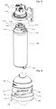
- FIG. 1 is an exploded perspective view of a water purification filter assembly, according to an embodiment of the present invention
- FIG. 2 is a perspective view showing part of the water purification filter assembly according to the embodiment of the present invention.
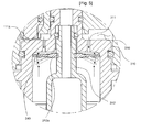
- FIG. 3 is a sectional view of FIG. 2 ;
- FIG. 4 is a bottom exploded perspective view of FIG. 2 ;
- FIG. 5 is a view showing the operation of an interruption ring according to the embodiment of the present invention.
- control valve 111a protrusion tip
- cylindrical space 220 slide slot
- head part 320 filter part
- filter part 321 handle
- FIG. 1 is an exploded perspective view of a water purification filter assembly according to an embodiment of the present invention.
- FIG. 2 is a perspective view showing part of the water purification filter assembly according to the embodiment of the present invention.
- FIG. 3 is a sectional view of FIG. 2 .
- FIG. 4 is a bottom exploded perspective view of FIG. 2 .
- FIG. 5 is a view showing the operation of an interruption ring according to the embodiment of the present invention.
- the water purification filter assembly includes a manifold 100, which is mounted to a water purifier, and a circular cap 200, which is provided under the lower end of the manifold 100, has slide slots 220 therein, and has protrusions 230 on a lower end thereof.
- the water purification filter assembly further includes a filter cartridge 300, which has a head part 310, coupled to the circular cap 200, and has a filter part 320, in which a filter is installed.
- the water purification filter assembly further includes fastening members 313, which are provided on the head part 310 to couple the filter cartridge 300 to the circular cap 200, guide grooves 330, which are formed in the upper surface of the filter part 320 so that the protrusions 230 of the circular cap 200 are inserted into the respective guide grooves 330, and the interruption ring 340, which is fitted over the outlet port 312 of the filter cartridge 300.
- the manifold 100 has therein an inlet passage 110, through which water is drawn, and an outlet passage 120, through which the water is discharged.
- a control valve 111 which controls the flow of water, is provided in the inlet passage 110.
- the circular cap 200 is provided under the lower end of the manifold 100.
- a cylindrical space 210 which communicates with the inlet passage 110 and the outlet passage 120, is formed in the circular cap 200.
- the slide slots 220 each of which has a slope part 221 to smoothly guide the associated fastening member 313, is formed in the circumferential inner surface of the circular cap 200.
- the protrusions 230 are provided under the lower end of the circular cap 200.
- the filter cartridge 300 is inserted into the cylindrical space 210 of the circular cap 200.
- the filter cartridge 300 includes the head part 310, which has therein inlet holes 311, through which water is supplied from the inlet passage 110, and has an outlet port 312, through which water is discharged to the outlet passage 120.
- the filter cartridge 300 further includes the filter part 320, which has therein the filter for purifying water.
- the fastening members 313 protrude at diametrically opposite positions from the circumferential outer surface of the head part 310 of the filter cartridge 300.
- the fastening members 313 are inserted into the respective slide slots 220 of the circular cap 200, thus fastening the filter cartridge 300 to the circular cap 200.
- the guide grooves 330 are formed in curved lines in the upper surface of the filter part 320 of the filter cartridge 300, so that the protrusions 230 of the circular cap 200 are inserted into the respective guide grooves 330.
- the guide grooves 330 are shaped such that the rotation of the filter cartridge 300 is guided by the protrusions 230.
- the guide grooves 330 are preferably formed at diametrically opposite positions in the upper surface of the filter cartridge 300.
- the protrusions 230 which are provided under the lower end of the circular cap 200, are disposed in right ends of the respective guide grooves 330 to have an arrangement such that the guide grooves 330 protrude to the left from the left ends of the respective slide slots 220.
- each fastening member 313 has on a right end thereof an inclined surface 313a such that the fastening member 313 can easily enter and slide along the associated slide slot 220. Furthermore, each fastening member 313 also has on a left end thereof an inclined surface 313a such that the fastening member 313 can be easily removed from the associated slide slot 220.
- a curved groove 314, which compresses the control valve 111 of the manifold 100 to open the control valve 111 when the filter cartridge is rotated, is formed in a perimeter portion of the upper surface of the head part 310.
- the curved groove 314 is reduced in depth in the direction in which the curved groove 314 compresses the control valve 111 upwards.
- the curved groove 314 serves as a cam having a shape such that it gradually compresses the control valve 111 upwards.
- a protrusion tip 111a is provided on the lower end of the control valve 111 to reduce the contact area between the control valve 111 and the curved groove 314.
- the protrusion tip 111a is brought into contact with and is compressed by the surface defining the curved groove 314.
- the protrusion tip 111a serves to reduce frictional force generated by contact between the control valve 111 and the curved groove 314 when the head part 310 is rotated by rotation of the filter cartridge 300, thus facilitating the rotation of the filter cartridge 300, and preventing the control valve 111 from being deformed by frictional force.
- the fastening members 313 provided on the head part 310 of the filter cartridge 300 are inserted into and locked to the respective slide slots 220 of the circular cap 200, thus fastening the filter cartridge 300 to the circular cap 200.
- the control valve 111 which is provided in the inlet passage 110 of the manifold 100, is moved upwards, so that the inlet passage 110 is opened. Thereby, water is supplied into the inlet holes 311 of the filter cartridge 300 through the inlet passage 110.
- the water, which has been supplied into the inlet holes 311, is purified by the filter and is thereafter discharged into the outlet passage 120 of the manifold 100 through the outlet port 312.
- the inlet holes 311 of the head part 310 are several circular holes, which are formed around the outlet port 312 in a circular arrangement.
- the interruption ring 340 which prevents water from flowing backwards through the inlet holes 311, is fitted into an insert groove 312a of the outlet port 312 of the filter cartridge 300.
- This interruption ring 340 is made of soft synthetic resin such that it can be elastically bent by water drawn through the inlet holes 311.
- the interruption ring 340 is disposed at a position adjacent to the inner surface of the upper end of the filter cartridge 300, thus preventing water, which has been purified by the filter part 320, from flowing backwards through the inlet holes 311.
- the interruption ring 340 is bent downwards by water drawn into the inlet holes 311, so that a gap is formed between the interruption ring 340 and the inner surface of the filter cartridge 300.
- water is drawn into the filter cartridge 300 through the gap.
- the interruption ring 340 is returned to its original state by its own elasticity. Thereafter, when purified water is discharged through the outlet port 312, because the interruption ring 340 is in the state of being in close contact with the inner surface of the filter cartridge 300, the purified water is prevented from being discharged through the inlet holes 311.
- a handle 321 for rotation of the filter cartridge 300 is provided under the lower surface of the filter part 320, which is concave, thus making it easy for the user to rotate the filter cartridge using the handle 321.
- the head part 320 of the filter cartridge 300 can be easily removed from the circular cap 200 by holding and rotating the handle 321.
- the slide slots 220 of the circular cap 200 are connected to respective curved surface parts 240, which are brought into contact with the respective fastening members 313 and are provided on the circumferential inner surface of the circular cap 200 to have downwardly inclined shapes such that the fastening members 313 are guided towards the lower end of the circular cap 200.
- the inclined surfaces 313a which correspond to curved surface parts 240, are provided in the respective fastening members 313.
- the fastening members 313 are removed from the respective slide slots 220 by rotating the filter cartridge 300 in a counterclockwise direction. At this time, because the slide slots 220 are connected to the respective curved surface parts 220, the fastening members 313 can smoothly slide in directions in which the respective curved surface parts 220 are inclined.
- the filter cartridge 300 receives the pressure of water supplied into the inlet holes 311, so that the head part 310 is biased by the pressure of water in the direction in which the head part 310 is separated from the circular cap 200. Therefore, the fastening members 313, which have been removed from the respective slide slots 220 by the rotation of the filter cartridge 300, can be easily moved along the curved surface parts 240 by the pressure of water. Therefore, the filter cartridge 300 can be easily separated from the circular cap 200.
Landscapes
- Chemical & Material Sciences (AREA)
- Chemical Kinetics & Catalysis (AREA)
- Life Sciences & Earth Sciences (AREA)
- Hydrology & Water Resources (AREA)
- Engineering & Computer Science (AREA)
- Environmental & Geological Engineering (AREA)
- Water Supply & Treatment (AREA)
- Organic Chemistry (AREA)
- Water Treatment By Sorption (AREA)
- Domestic Plumbing Installations (AREA)
- Separation Using Semi-Permeable Membranes (AREA)
Applications Claiming Priority (2)
| Application Number | Priority Date | Filing Date | Title |
|---|---|---|---|
| KR1020060056986A KR100718566B1 (ko) | 2006-06-23 | 2006-06-23 | 정수기 필터 어셈블리 |
| PCT/KR2006/005519 WO2007148862A1 (en) | 2006-06-23 | 2006-12-18 | Water purification filter assembly |
Publications (3)
| Publication Number | Publication Date |
|---|---|
| EP2038036A1 EP2038036A1 (en) | 2009-03-25 |
| EP2038036A4 EP2038036A4 (en) | 2010-05-19 |
| EP2038036B1 true EP2038036B1 (en) | 2012-08-15 |
Family
ID=38270816
Family Applications (1)
| Application Number | Title | Priority Date | Filing Date |
|---|---|---|---|
| EP06835236A Expired - Fee Related EP2038036B1 (en) | 2006-06-23 | 2006-12-18 | Water purification filter assembly |
Country Status (6)
| Country | Link |
|---|---|
| US (1) | US20100000919A1 (ko) |
| EP (1) | EP2038036B1 (ko) |
| JP (1) | JP4960448B2 (ko) |
| KR (1) | KR100718566B1 (ko) |
| CN (1) | CN101466449B (ko) |
| WO (1) | WO2007148862A1 (ko) |
Families Citing this family (10)
| Publication number | Priority date | Publication date | Assignee | Title |
|---|---|---|---|---|
| DE102010011290A1 (de) * | 2010-03-13 | 2011-09-15 | Mahle International Gmbh | Filtereinrichtung |
| DE102010063088B3 (de) * | 2010-12-14 | 2012-02-23 | Brita Gmbh | Vorrichtung zum Behandeln einer Flüssigkeit |
| KR101323891B1 (ko) | 2011-07-08 | 2013-10-30 | 엘지전자 주식회사 | 정수기 |
| US20130206654A1 (en) | 2011-09-07 | 2013-08-15 | Electrolytic Ozone Inc. | Hub and removable cartridge for producing and delivering ozonated water |
| BR112014007066B1 (pt) * | 2013-01-30 | 2022-04-12 | Zhejiang Qinyuan Water Treatment S.T. Co. Ltd | Um elemento filtrante composto e seu soquete |
| KR101496224B1 (ko) * | 2013-11-07 | 2015-02-27 | 장진용 | 정수기용 필터 카트리지의 체결 확인장치 |
| US20160129380A1 (en) | 2014-11-06 | 2016-05-12 | 3M Innovative Properties Company | Replacement filter cartridge |
| ES2720280T3 (es) * | 2015-02-05 | 2019-07-19 | Holger Knappe | Cabezal de distribución modular para cuerpo de carcasa de membrana |
| WO2018074028A1 (ja) * | 2016-10-18 | 2018-04-26 | 三浦工業株式会社 | 逆止弁 |
| US11123667B2 (en) * | 2018-06-11 | 2021-09-21 | Bhrs Group | Water cooler filter with secure bayonet-type connection |
Family Cites Families (13)
| Publication number | Priority date | Publication date | Assignee | Title |
|---|---|---|---|---|
| US3640390A (en) * | 1968-05-13 | 1972-02-08 | Torite Enterprises Inc | Replaceable cartridge filter housing |
| JPS583910U (ja) * | 1981-06-26 | 1983-01-11 | オルガノ株式会社 | 自動販売機用のカ−トリツジ式濾過器 |
| US4735716A (en) * | 1986-01-27 | 1988-04-05 | Cuno Corporated | Quick-change filter cartridge and head therefor |
| JP2859475B2 (ja) * | 1991-10-07 | 1999-02-17 | 和興産業株式会社 | スピンオンフィルターおよびそのフィルター用エレメント組立体 |
| JPH0731970A (ja) * | 1993-07-22 | 1995-02-03 | Sanden Corp | 浄水殺菌装置の吸着剤再生方法 |
| US20020036162A1 (en) * | 1996-08-08 | 2002-03-28 | Magnusson Jan H. | Appliance with iodinated water source |
| CA2304271A1 (en) * | 1999-04-21 | 2000-10-21 | Emhart Inc. | Above deck mountable filter cartridge for a filter assembly |
| RU2248836C2 (ru) * | 1999-10-12 | 2005-03-27 | Роджер П. РЕЙД | Сменный фильтр, способный повторно перерабатываться, и емкость под давлением |
| JP3729085B2 (ja) * | 2001-02-23 | 2005-12-21 | 株式会社Inax | 無機質濾材、浄水カートリッジ及び浄水器 |
| US20020166805A1 (en) * | 2001-03-21 | 2002-11-14 | Minns Gian D. | Filter assembly and method of manufacture |
| US20030019819A1 (en) * | 2001-07-30 | 2003-01-30 | Karl Fritze | Hot disconnect replaceable water filter assembly |
| KR100494591B1 (ko) * | 2002-08-28 | 2005-06-10 | 웅진코웨이주식회사 | 정수기의 필터 장치 |
| KR100494595B1 (ko) * | 2002-11-14 | 2005-06-10 | 웅진코웨이주식회사 | 정수기의 필터 장치 |
-
2006
- 2006-06-23 KR KR1020060056986A patent/KR100718566B1/ko active IP Right Grant
- 2006-12-18 US US12/299,462 patent/US20100000919A1/en not_active Abandoned
- 2006-12-18 WO PCT/KR2006/005519 patent/WO2007148862A1/en active Application Filing
- 2006-12-18 JP JP2009517942A patent/JP4960448B2/ja not_active Expired - Fee Related
- 2006-12-18 CN CN2006800549807A patent/CN101466449B/zh not_active Expired - Fee Related
- 2006-12-18 EP EP06835236A patent/EP2038036B1/en not_active Expired - Fee Related
Also Published As
| Publication number | Publication date |
|---|---|
| EP2038036A1 (en) | 2009-03-25 |
| CN101466449B (zh) | 2012-06-13 |
| EP2038036A4 (en) | 2010-05-19 |
| JP2010504185A (ja) | 2010-02-12 |
| CN101466449A (zh) | 2009-06-24 |
| JP4960448B2 (ja) | 2012-06-27 |
| WO2007148862A1 (en) | 2007-12-27 |
| KR100718566B1 (ko) | 2007-05-15 |
| US20100000919A1 (en) | 2010-01-07 |
Similar Documents
| Publication | Publication Date | Title |
|---|---|---|
| EP2038031B1 (en) | Water purification filter assembly | |
| EP2038036B1 (en) | Water purification filter assembly | |
| US8017008B2 (en) | Water purification filter assembly | |
| EP3069772B1 (en) | Filter assembly | |
| US6426001B1 (en) | Cartridge adapter | |
| US10293287B2 (en) | Water filter assembly | |
| US5914037A (en) | Filter device for a water filter | |
| EP2537569A1 (en) | Water filter assembly and refrigerator and water purifier having the same | |
| KR200384558Y1 (ko) | 정수장치의 필터 장착구조 | |
| KR200449287Y1 (ko) | 정수장치의 필터 회전구조 | |
| KR200403991Y1 (ko) | 정수기용 필터장치 | |
| WO2009025413A1 (en) | Water purifier filter having a filter washing function | |
| US7360558B1 (en) | Control valve for drinking water fountain | |
| KR20150002961U (ko) | 정수 필터용 커넥터 | |
| KR20120025164A (ko) | 회전체결식 필터카트리지 결합 장치 | |
| KR200190745Y1 (ko) | 정수기용 필터어셈블리 | |
| KR0161086B1 (ko) | 정수기의 카트리지형 여과장치 | |
| TWI805280B (zh) | 淨水用的濾心組 | |
| KR102326205B1 (ko) | 정수용 필터카트리지 | |
| US20230373818A1 (en) | A water treatment cartridge for a water treatment device, a head of a water treatment device and a water treatment device comprising such a cartridge and such a head | |
| KR20090111455A (ko) | 정수장치의 필터 장착구조 | |
| JP2000210657A (ja) | 浄水器 |
Legal Events
| Date | Code | Title | Description |
|---|---|---|---|
| PUAI | Public reference made under article 153(3) epc to a published international application that has entered the european phase |
Free format text: ORIGINAL CODE: 0009012 |
|
| 17P | Request for examination filed |
Effective date: 20081219 |
|
| AK | Designated contracting states |
Kind code of ref document: A1 Designated state(s): AT BE BG CH CY CZ DE DK EE ES FI FR GB GR HU IE IS IT LI LT LU LV MC NL PL PT RO SE SI SK TR |
|
| AX | Request for extension of the european patent |
Extension state: AL BA HR MK RS |
|
| RBV | Designated contracting states (corrected) |
Designated state(s): DE FR GB IT NL SE |
|
| A4 | Supplementary search report drawn up and despatched |
Effective date: 20100416 |
|
| 17Q | First examination report despatched |
Effective date: 20110801 |
|
| GRAP | Despatch of communication of intention to grant a patent |
Free format text: ORIGINAL CODE: EPIDOSNIGR1 |
|
| DAX | Request for extension of the european patent (deleted) | ||
| GRAS | Grant fee paid |
Free format text: ORIGINAL CODE: EPIDOSNIGR3 |
|
| GRAA | (expected) grant |
Free format text: ORIGINAL CODE: 0009210 |
|
| AK | Designated contracting states |
Kind code of ref document: B1 Designated state(s): DE FR GB IT NL SE |
|
| REG | Reference to a national code |
Ref country code: GB Ref legal event code: FG4D |
|
| REG | Reference to a national code |
Ref country code: DE Ref legal event code: R096 Ref document number: 602006031511 Country of ref document: DE Effective date: 20121018 |
|
| REG | Reference to a national code |
Ref country code: SE Ref legal event code: TRGR |
|
| REG | Reference to a national code |
Ref country code: NL Ref legal event code: T3 |
|
| PLBE | No opposition filed within time limit |
Free format text: ORIGINAL CODE: 0009261 |
|
| STAA | Information on the status of an ep patent application or granted ep patent |
Free format text: STATUS: NO OPPOSITION FILED WITHIN TIME LIMIT |
|
| 26N | No opposition filed |
Effective date: 20130516 |
|
| REG | Reference to a national code |
Ref country code: DE Ref legal event code: R097 Ref document number: 602006031511 Country of ref document: DE Effective date: 20130516 |
|
| REG | Reference to a national code |
Ref country code: FR Ref legal event code: PLFP Year of fee payment: 10 |
|
| REG | Reference to a national code |
Ref country code: FR Ref legal event code: PLFP Year of fee payment: 11 |
|
| REG | Reference to a national code |
Ref country code: FR Ref legal event code: PLFP Year of fee payment: 12 |
|
| PGFP | Annual fee paid to national office [announced via postgrant information from national office to epo] |
Ref country code: DE Payment date: 20180222 Year of fee payment: 12 |
|
| PGFP | Annual fee paid to national office [announced via postgrant information from national office to epo] |
Ref country code: SE Payment date: 20181219 Year of fee payment: 13 Ref country code: NL Payment date: 20181217 Year of fee payment: 13 |
|
| PGFP | Annual fee paid to national office [announced via postgrant information from national office to epo] |
Ref country code: FR Payment date: 20181218 Year of fee payment: 13 Ref country code: GB Payment date: 20181219 Year of fee payment: 13 Ref country code: IT Payment date: 20181218 Year of fee payment: 13 |
|
| REG | Reference to a national code |
Ref country code: DE Ref legal event code: R119 Ref document number: 602006031511 Country of ref document: DE |
|
| PG25 | Lapsed in a contracting state [announced via postgrant information from national office to epo] |
Ref country code: DE Free format text: LAPSE BECAUSE OF NON-PAYMENT OF DUE FEES Effective date: 20190702 |
|
| REG | Reference to a national code |
Ref country code: SE Ref legal event code: EUG |
|
| REG | Reference to a national code |
Ref country code: NL Ref legal event code: MM Effective date: 20200101 |
|
| GBPC | Gb: european patent ceased through non-payment of renewal fee |
Effective date: 20191218 |
|
| PG25 | Lapsed in a contracting state [announced via postgrant information from national office to epo] |
Ref country code: NL Free format text: LAPSE BECAUSE OF NON-PAYMENT OF DUE FEES Effective date: 20200101 |
|
| PG25 | Lapsed in a contracting state [announced via postgrant information from national office to epo] |
Ref country code: FR Free format text: LAPSE BECAUSE OF NON-PAYMENT OF DUE FEES Effective date: 20191231 Ref country code: IT Free format text: LAPSE BECAUSE OF NON-PAYMENT OF DUE FEES Effective date: 20191218 Ref country code: GB Free format text: LAPSE BECAUSE OF NON-PAYMENT OF DUE FEES Effective date: 20191218 Ref country code: SE Free format text: LAPSE BECAUSE OF NON-PAYMENT OF DUE FEES Effective date: 20191219 |