EP2037777B1 - Babysitter with bottom frame - Google Patents
Babysitter with bottom frame Download PDFInfo
- Publication number
- EP2037777B1 EP2037777B1 EP07748327.9A EP07748327A EP2037777B1 EP 2037777 B1 EP2037777 B1 EP 2037777B1 EP 07748327 A EP07748327 A EP 07748327A EP 2037777 B1 EP2037777 B1 EP 2037777B1
- Authority
- EP
- European Patent Office
- Prior art keywords
- backrest
- support plate
- frame
- base frame
- yoke
- Prior art date
- Legal status (The legal status is an assumption and is not a legal conclusion. Google has not performed a legal analysis and makes no representation as to the accuracy of the status listed.)
- Active
Links
- 230000015572 biosynthetic process Effects 0.000 claims description 2
- 230000014759 maintenance of location Effects 0.000 claims description 2
- 238000005553 drilling Methods 0.000 claims 1
- 239000004753 textile Substances 0.000 claims 1
- 239000004744 fabric Substances 0.000 description 3
- 239000002783 friction material Substances 0.000 description 2
- 230000007704 transition Effects 0.000 description 2
- 238000010276 construction Methods 0.000 description 1
- 230000001419 dependent effect Effects 0.000 description 1
- 210000003128 head Anatomy 0.000 description 1
- 210000001331 nose Anatomy 0.000 description 1
Images

Classifications
-
- A—HUMAN NECESSITIES
- A47—FURNITURE; DOMESTIC ARTICLES OR APPLIANCES; COFFEE MILLS; SPICE MILLS; SUCTION CLEANERS IN GENERAL
- A47D—FURNITURE SPECIALLY ADAPTED FOR CHILDREN
- A47D13/00—Other nursery furniture
- A47D13/10—Rocking-chairs; Indoor swings ; Baby bouncers
- A47D13/107—Rocking-chairs; Indoor swings ; Baby bouncers resiliently suspended or supported, e.g. baby bouncers
-
- A—HUMAN NECESSITIES
- A47—FURNITURE; DOMESTIC ARTICLES OR APPLIANCES; COFFEE MILLS; SPICE MILLS; SUCTION CLEANERS IN GENERAL
- A47D—FURNITURE SPECIALLY ADAPTED FOR CHILDREN
- A47D1/00—Children's chairs
- A47D1/002—Children's chairs adjustable
-
- A—HUMAN NECESSITIES
- A47—FURNITURE; DOMESTIC ARTICLES OR APPLIANCES; COFFEE MILLS; SPICE MILLS; SUCTION CLEANERS IN GENERAL
- A47D—FURNITURE SPECIALLY ADAPTED FOR CHILDREN
- A47D13/00—Other nursery furniture
- A47D13/08—Devices for use in guiding or supporting children, e.g. safety harnesses
-
- Y—GENERAL TAGGING OF NEW TECHNOLOGICAL DEVELOPMENTS; GENERAL TAGGING OF CROSS-SECTIONAL TECHNOLOGIES SPANNING OVER SEVERAL SECTIONS OF THE IPC; TECHNICAL SUBJECTS COVERED BY FORMER USPC CROSS-REFERENCE ART COLLECTIONS [XRACs] AND DIGESTS
- Y10—TECHNICAL SUBJECTS COVERED BY FORMER USPC
- Y10S—TECHNICAL SUBJECTS COVERED BY FORMER USPC CROSS-REFERENCE ART COLLECTIONS [XRACs] AND DIGESTS
- Y10S297/00—Chairs and seats
- Y10S297/11—Baby bouncer
Definitions
- the invention relates to a bouncing cradle, or bouncy chair, having a base frame, of the kind that is seen in the preamble of the appended independent claim 1.
- the invention relates to a bouncing cradle (children's reclining chair) of the kind that comprises a base frame, which is intended to rest on an underlay such as a floor, a backrest for carrying a child, a pivot mounting arranged for the backrest and carried by the base frame, an arm fixedly connected to the backrest and situated under the backrest as well as at a distance from the pivot mounting, the arm being connected to an adjustment fitting that rests against the base frame at a distance from the pivot mounting, for setting different angles of inclination of the backrest in relation to the base frame.
- the base frame may, for instance, have a fixed bar for supporting the adjustment fitting, and the adjustment fitting may have two or more recesses with different distances from the connection of the adjustment fitting to the arm, wherein the effective length of the adjustment fitting can be varied by the selection of the recess that is brought into engagement with the bar.
- the adjustment fitting is arranged to allow the backrest to be folded into a position close by the base frame, (transportation of the bouncing cradle).
- the base frame should have three support points against the underlay, and further, the base frame should be provided with a pivot mounting for the backrest.
- the base frame of a substantially plane yoke, the branch ends of which are attached to a relatively small support plate that carries the pivot mounting of the backrest.
- the bottom web of the yoke has a considerably greater width than the distance between the branch ends thereof, and the branch ends should furthermore be attached to the support plate above the underlay surface thereof.
- corner areas between the bottom web and branches of the yoke are suitably formed so as to form two spaced-apart support points against the underlay, the support plate forming the third support point.
- the base frame has three support points against the underlay, it can lie stably also on an uneven floor.
- a previously known bouncing cradle is known from US 5507564 .
- An object of the invention is to provide a new design of the support plate and the attachment of the yoke branches to the same, in order to entirely or partly obviate the drawbacks outlined above.
- An additional object is to provide a support plate that, in the axial direction of the pivot mounting of the backrest, affords a centring of the pivotally mounted part of the backrest.
- An additional object is to provide a support plate that automatically affords a detachable locking of the backrest in a transportation position, i.e., when the backrest is lowered against and close by the base frame.
- the object is entirely or partly attained by the invention.
- the backrest frame 25 is supplemented by two straight and axially aligned frame pieces 24 and a generally U-shaped yoke integratedly attached between the same.
- the frame pieces 24 are received in a pivot mounting 12 along a straight edge 13 of a support plate 16 belonging to a base frame 10, which is intended to stably rest on a horizontal underlay.
- An essentially flat yoke of a generally triangular nature has the free ends 66 thereof parallel to and attached in the support plate. At a distance from the ends 66, the yoke is widened so as to form two support points, which are laterally spaced-apart in relation to the backrest 20. Said two support points may be established by friction material applied on the underside of the yoke in the corner areas of the yoke between the web and the branches.
- the support plate 16 may, on the underside along the circumference border thereof, be provided with a strand of friction material, for instance rubber, as anti-skid protection.
- a bar 14 extends between the yoke ends 66, the bar 16 being received in the respective hole in the yoke end parts.
- An adjustment fitting 40 has a pivot mounting 23 for the web part 22 of the U-shaped part of the backrest frame.
- the bar 14 and the arm 22 are approximately at the same distance from the pivot mounting 12, and that the adjustment fitting 40 has an elongate opening 60 having a side 60, which is turned obliquely downward and facing the first pivot mounting 12 and in which recesses 51, 52, 53 are situated.
- Each recess has a bottom part 62 that supports the bar 14, and a mouth portion 63 that, obliquely downward and toward the first pivot mounting, mouths in the opening 60.
- the bar 14, the arm 22 and the pivot mountings 12, 23 are axially parallel.
- the elongate opening 60 is delimited toward the upper end thereof by a locking arm 70, which is pivotally mounted around a spindle 71 in the vicinity of the pivot mounting 23, and is biased by a spring 72 toward the end position shown.
- the bar 14 can always, from the opening 60, slide on surfaces inclined to the vertical into the bottom portion 62 of a recess, when the backrest is loaded vertically. From Figure 6 , it is possible to further see that the mouth portion 63 of the recess has a width that is greater than the diameter of the bar 14, and that the bottom portion 62 of the recess at the upper part thereof is undercut in order to stably receive the bar 14 and prevent the bar 14 from sliding out of the recess, when the backrest is vertically loaded, independently of which recess the bar 14 is received in.
- the locking arm 70 is biased against a stopper 74.
- the arm 70 can be turned manually against the action of the spring 73 and, in doing so, brings the opening 60 in communication with an additional elongate opening 80 in the fitting 40, the opening 80 extending up to the area of the pivot mounting 23.
- the fitting 40 has a gripping ear 90, which facilitates manual turning of the fitting 40 around the mounting 22, 23.
- Figure 3 illustrates that the bar 14 is in the recess 52, and that it is desirable to convert the bouncing cradle into a transportation position in which the backrest is generally parallel and next to the base frame 10. In doing so, the locking arm 70 is turned back against the action of the spring 73 in the direction of the arrow indicated in Figure 3 , so that the fitting 40 can be turned in such a manner that the bar 14 leaves the recess 52 and runs along the opening 60 and inward toward the opening 80, such as is indicated by the arrow in Figure 4 .
- Figure 7 illustrates that the support plate 16 has a pair of integrated sleeves 85, which receive the ends 66 of the yoke 84. Furthermore, it is seen that the sleeves 85 as well as the yoke ends 66 have vertically aligned through holes, and that a bolt joint extends therethrough.
- the bolt joint is shown to have a nut at the top and has a screw head at the bottom.
- the straight front edge 13 of the support plate has a groove that receives the straight frame pieces 24.
- the U-yoke part 37, the bottom web of which forms the arm 22, is carried by the frame pieces 24 via the pair of arms 21.
- the screw heads 86 of the bolt joints confine the straight frame pieces 24 in the grooves in the support plate 16.
- the integrated sleeves 85 afford a stable high-strength connection to the support plate 16, and afford, by means of the bolt joints, a simple connection of the yoke 84 to the support plate 16. From Figure 7 , it is possible to further see that the support plate has integrated buttons 28 that, in addition to confining the frame pieces 24, also afford anchorage of the lower border part of the bag that is threaded onto the frame part 25 for the formation of the backrest 20. In that connection, the front part of the bag has buttonhole openings in alignment with the buttons 28, whereby a stable anchorage of the bag in the stretched state is attained.
- the support plate 16 has a projecting U-girder 110, which is situated between the sleeves 85 and is integrated with the injection-moulded support plate 16.
- the bottom web 111 of the girder 110 is situated at the topside of the support plate, and the branches 112 thereof extend downward therefrom.
- the distance between the outsides of the branches is somewhat smaller than the free distance between the branch arms 21 of the U-yoke 37. In this way, the U-yoke 37 is centred and thereby the backrest 20 in relation to the base frame, when the U-yoke is turned down over the U-girder.
- the free branch ends of the girder 110 have generally wedge-shaped protuberances or noses 115 at least at the free end of the girder, an interference between said protuberances 115 and the arms 21 is afforded, and the arms 21 are locked detachably under said protuberances 114 when the arms 21 have passed past them.
- the branches 112 are elastically resilient and also allow, thanks to a wedge surface 113, a turning back of the U-yoke piece 37 past the arms 21, so that the branches are driven toward each other upon the turning back of the U-yoke 37 away from the transportation position. That is, the branch ends having the wedge surfaces 113, 114 form a detachable catch for the retention of the backrest next to the base frame in the transportation position.
- the recesses 51, 52, 53 allow free passage of the bar 14 to and from the bottom portion 62, with the exception of a small dog 64 possibly being arranged at the transition between the mouth portion 63 and bottom part 62 of the recess in the upper wall of the recess.
- Said dog 64 forms, together with the opposite recess wall, a waist that is somewhat smaller than the diameter of the bar 14. Thanks to an elastic resiliency of the opposite walls of the recess in the vicinity of said dog 64, a snap-locking function is afforded that blocks the bar 14 from unintentionally leaving the bottom part 62 of the recess.
- the undercut of the upper side wall of the recess in the bottom part serves to guarantee that the bar 14 cannot leave the recess upon loading of the backrest in the direction of the base frame.
- the upper side wall of the recess leans at an angle ⁇ ⁇ 90° to the line 29 between the centres of the bar 14 and of the arm part 22.
- the lower side wall of the recess leans as is seen from Figure 6 , at an angle ⁇ > 90° to the line 29.
- the bar 14 will be able to slide along the upper smooth opening wall, when the backrest is loaded.
- the bar 14 then is introduced into a recess 52, 53, the bar will 14 easily slide along the upper smooth mouth wall of the recess, which also has a substantial inclination to the horizontal, and passes into the bottom part 62 of the recess.
- the bar 14 automatically makes for one of the recesses 51-53 upon loading of the backrest.
- each sleeve 85 has a nut socket 87, which rotationally secures a lock nut that receives a through screw, the head of which radially projects from the diametrically opposed side of the sleeve and screens off the groove in order to locally restrain a straight frame piece 24 therein.
- the same is restrained in the groove by a respective dog 64.
- the screw is suitably of the Allen-type and the nut 87 is suitably a lock nut having friction inserts.
Abstract
Description
- The invention relates to a bouncing cradle, or bouncy chair, having a base frame, of the kind that is seen in the preamble of the appended independent claim 1.
- Thus, the invention relates to a bouncing cradle (children's reclining chair) of the kind that comprises a base frame, which is intended to rest on an underlay such as a floor, a backrest for carrying a child, a pivot mounting arranged for the backrest and carried by the base frame, an arm fixedly connected to the backrest and situated under the backrest as well as at a distance from the pivot mounting, the arm being connected to an adjustment fitting that rests against the base frame at a distance from the pivot mounting, for setting different angles of inclination of the backrest in relation to the base frame. The base frame may, for instance, have a fixed bar for supporting the adjustment fitting, and the adjustment fitting may have two or more recesses with different distances from the connection of the adjustment fitting to the arm, wherein the effective length of the adjustment fitting can be varied by the selection of the recess that is brought into engagement with the bar. By bringing different recesses into engagement with the bar, it is possible to set a number of preselected using positions of the backrest, for instance inclination positions that are suitable for a number of different things to do for the child, such as play, rest, sleep. Furthermore, the adjustment fitting is arranged to allow the backrest to be folded into a position close by the base frame, (transportation of the bouncing cradle).
- The base frame should have three support points against the underlay, and further, the base frame should be provided with a pivot mounting for the backrest. In that connection, it is known to form the base frame of a substantially plane yoke, the branch ends of which are attached to a relatively small support plate that carries the pivot mounting of the backrest.
- Suitably, the bottom web of the yoke has a considerably greater width than the distance between the branch ends thereof, and the branch ends should furthermore be attached to the support plate above the underlay surface thereof.
- The corner areas between the bottom web and branches of the yoke are suitably formed so as to form two spaced-apart support points against the underlay, the support plate forming the third support point.
- By the fact that the base frame has three support points against the underlay, it can lie stably also on an uneven floor.
- However, in previously known bouncing cradles, the fastening of the yoke to the support plate is delicate in respect of stability and strength, especially because of the load variations that arise because of the play of the child while the child uses the bouncing cradle. Furthermore, in a previously known bouncing cradle construction, it is relatively difficult to establish a pivot mounting for the backrest durable over time.
- A previously known bouncing cradle is known from
US 5507564 . An object of the invention is to provide a new design of the support plate and the attachment of the yoke branches to the same, in order to entirely or partly obviate the drawbacks outlined above. - An additional object is to provide a support plate that, in the axial direction of the pivot mounting of the backrest, affords a centring of the pivotally mounted part of the backrest.
- An additional object is to provide a support plate that automatically affords a detachable locking of the backrest in a transportation position, i.e., when the backrest is lowered against and close by the base frame.
- Additional objects and advantages of the invention are seen in the appended claims and the appended drawing and the description.
- The object is entirely or partly attained by the invention.
- The invention is defined in the appended independent claim. Embodiments of the invention are defined in the appended dependent claims.
- In the following, an embodiment of the invention will be described by way of examples, reference being made to the appended drawing.
-
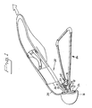
Figure 1 schematically and in perspective shows a bouncing cradle. -
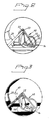
Figure 2 shows an enlarged depiction of a detail of the bouncing cradle according toFigure 1 , comprising an inclination adjustment fitting. -
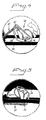
Figures 3 ,4, 5 show in depictions corresponding toFigure 2 , different rotary positions of the adjustment fitting upon transition from an inclination-determining using position, into a transportation position of the bouncing cradle. -
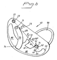
Figure 6 shows a broken-away side view of the adjustment fitting. -
Figure 7 shows a planar view of a support plate belonging to the base frame. -
Figure 8 shows a view taken along the line VIII-VIII inFigure 7 . -
Figure 9 shows a section taken along the line A-A inFigure 8. -
Figure 1 illustrates a bouncing cradle comprising abackrest 20, which is formed of a generallyU-shaped frame part 25 on which a cloth bag is to be pulled on so as to form a reclining support for an infant. (InFigure 1 , the bag is shown not fully pulled on, for reasons of lucidity. On the cloth bag, a pair of cloth trousers is shown, into which the child should be put down). - The
backrest frame 25 is supplemented by two straight and axially alignedframe pieces 24 and a generally U-shaped yoke integratedly attached between the same. - The
frame pieces 24 are received in a pivot mounting 12 along astraight edge 13 of asupport plate 16 belonging to abase frame 10, which is intended to stably rest on a horizontal underlay. An essentially flat yoke of a generally triangular nature has thefree ends 66 thereof parallel to and attached in the support plate. At a distance from theends 66, the yoke is widened so as to form two support points, which are laterally spaced-apart in relation to thebackrest 20. Said two support points may be established by friction material applied on the underside of the yoke in the corner areas of the yoke between the web and the branches. Thesupport plate 16 may, on the underside along the circumference border thereof, be provided with a strand of friction material, for instance rubber, as anti-skid protection. - It can be seen that a
bar 14 extends between theyoke ends 66, thebar 16 being received in the respective hole in the yoke end parts. - An adjustment fitting 40 has a pivot mounting 23 for the
web part 22 of the U-shaped part of the backrest frame. - From
Figures 2 and6 , it can be understood that thebar 14 and thearm 22 are approximately at the same distance from the pivot mounting 12, and that the adjustment fitting 40 has anelongate opening 60 having aside 60, which is turned obliquely downward and facing the first pivot mounting 12 and in which recesses 51, 52, 53 are situated. Each recess has abottom part 62 that supports thebar 14, and amouth portion 63 that, obliquely downward and toward the first pivot mounting, mouths in the opening 60. Thebar 14, thearm 22 and thepivot mountings - The
elongate opening 60 is delimited toward the upper end thereof by alocking arm 70, which is pivotally mounted around aspindle 71 in the vicinity of the pivot mounting 23, and is biased by a spring 72 toward the end position shown. - By the inclinations accounted for, the
bar 14 can always, from theopening 60, slide on surfaces inclined to the vertical into thebottom portion 62 of a recess, when the backrest is loaded vertically. FromFigure 6 , it is possible to further see that themouth portion 63 of the recess has a width that is greater than the diameter of thebar 14, and that thebottom portion 62 of the recess at the upper part thereof is undercut in order to stably receive thebar 14 and prevent thebar 14 from sliding out of the recess, when the backrest is vertically loaded, independently of which recess thebar 14 is received in. - From
Figure 6 , it can be seen that thelocking arm 70 in the shown end position thereof, by the side thereof facing the opening 60, intersects the upper mouth wall of therecess 51 and forms a guide surface for the introduction of thebar 14 from the opening 60 into the mouth part of therecess 51. - By means of a
bias spring 73, thelocking arm 70 is biased against astopper 74. Thearm 70 can be turned manually against the action of thespring 73 and, in doing so, brings the opening 60 in communication with an additionalelongate opening 80 in thefitting 40, the opening 80 extending up to the area of thepivot mounting 23. - Furthermore, it can be seen that on the outside thereof, the
fitting 40 has a grippingear 90, which facilitates manual turning of thefitting 40 around themounting Figure 3 illustrates that thebar 14 is in therecess 52, and that it is desirable to convert the bouncing cradle into a transportation position in which the backrest is generally parallel and next to thebase frame 10. In doing so, thelocking arm 70 is turned back against the action of thespring 73 in the direction of the arrow indicated inFigure 3 , so that thefitting 40 can be turned in such a manner that thebar 14 leaves therecess 52 and runs along the opening 60 and inward toward the opening 80, such as is indicated by the arrow inFigure 4 . Upon continued turning of thefitting 40 around themounting fitting 40 is continued according toFigure 4 until thefitting 40 assumes the position shown inFigure 5 , in which thepivot mounting 23 is situated in the vicinity of the bar 14 (not shown), the bouncing cradle having assumed the transportation position. In the transportation position, the U-yokepart 37 extends at an angle under the plane of thebase frame 10, and theweb 22 thereof is situated on a level under thebar 14. -
Figure 7 illustrates that thesupport plate 16 has a pair of integratedsleeves 85, which receive theends 66 of theyoke 84. Furthermore, it is seen that thesleeves 85 as well as theyoke ends 66 have vertically aligned through holes, and that a bolt joint extends therethrough. The bolt joint is shown to have a nut at the top and has a screw head at the bottom. The straightfront edge 13 of the support plate has a groove that receives thestraight frame pieces 24. The U-yokepart 37, the bottom web of which forms thearm 22, is carried by theframe pieces 24 via the pair ofarms 21. - The
screw heads 86 of the bolt joints confine thestraight frame pieces 24 in the grooves in thesupport plate 16. The integratedsleeves 85 afford a stable high-strength connection to thesupport plate 16, and afford, by means of the bolt joints, a simple connection of theyoke 84 to thesupport plate 16. FromFigure 7 , it is possible to further see that the support plate has integratedbuttons 28 that, in addition to confining theframe pieces 24, also afford anchorage of the lower border part of the bag that is threaded onto theframe part 25 for the formation of thebackrest 20. In that connection, the front part of the bag has buttonhole openings in alignment with thebuttons 28, whereby a stable anchorage of the bag in the stretched state is attained. - From
Figures 7 and 8 , it can be seen that thesupport plate 16 has a projecting U-girder 110, which is situated between thesleeves 85 and is integrated with the injection-moulded support plate 16. Thebottom web 111 of thegirder 110 is situated at the topside of the support plate, and thebranches 112 thereof extend downward therefrom. The distance between the outsides of the branches is somewhat smaller than the free distance between thebranch arms 21 of the U-yoke 37. In this way, the U-yoke 37 is centred and thereby thebackrest 20 in relation to the base frame, when the U-yoke is turned down over the U-girder. By the fact that the free branch ends of thegirder 110 have generally wedge-shaped protuberances ornoses 115 at least at the free end of the girder, an interference between saidprotuberances 115 and thearms 21 is afforded, and thearms 21 are locked detachably under saidprotuberances 114 when thearms 21 have passed past them. Thebranches 112 are elastically resilient and also allow, thanks to awedge surface 113, a turning back of theU-yoke piece 37 past thearms 21, so that the branches are driven toward each other upon the turning back of the U-yoke 37 away from the transportation position. That is, the branch ends having the wedge surfaces 113, 114 form a detachable catch for the retention of the backrest next to the base frame in the transportation position. - Finally, from
Figure 6 , it can be understood that therecesses bar 14 to and from thebottom portion 62, with the exception of asmall dog 64 possibly being arranged at the transition between themouth portion 63 andbottom part 62 of the recess in the upper wall of the recess. Saiddog 64 forms, together with the opposite recess wall, a waist that is somewhat smaller than the diameter of thebar 14. Thanks to an elastic resiliency of the opposite walls of the recess in the vicinity of saiddog 64, a snap-locking function is afforded that blocks thebar 14 from unintentionally leaving thebottom part 62 of the recess. The undercut of the upper side wall of the recess in the bottom part serves to guarantee that thebar 14 cannot leave the recess upon loading of the backrest in the direction of the base frame. - The upper side wall of the recess leans at an angle β < 90° to the
line 29 between the centres of thebar 14 and of thearm part 22. The lower side wall of the recess leans, as is seen fromFigure 6 , at an angle α > 90° to theline 29. - By the fact that the upper wall of the
elongate opening 60 has a substantial inclination to the horizontal, independently of the position of thebar 14 along theopening 60, thebar 14 will be able to slide along the upper smooth opening wall, when the backrest is loaded. When thebar 14 then is introduced into arecess bottom part 62 of the recess. Hence, thebar 14 automatically makes for one of the recesses 51-53 upon loading of the backrest. - From
Figures 7-9 , it is possible to further see that eachsleeve 85 has anut socket 87, which rotationally secures a lock nut that receives a through screw, the head of which radially projects from the diametrically opposed side of the sleeve and screens off the groove in order to locally restrain astraight frame piece 24 therein. At the other end of the frame piece, the same is restrained in the groove by arespective dog 64. The screw is suitably of the Allen-type and thenut 87 is suitably a lock nut having friction inserts.
Claims (8)
- A bouncing cradle comprising a base frame (10) intended to rest on an underlay, a backrest (20), a pivot mounting (12) arranged for the backrest and carried by the base frame, an arm (22) fixedly connected to the backrest and situated under the backrest (20) as well as at a distance from the pivot mounting, and an adjustment fitting (40) for setting different angles of inclination of the backrest in relation to the base frame, the base frame comprising an essentially plane support yoke (84), the branch ends of which are attached to a support plate (16), wherein the support plate (16) consists of an injectionmoulded piece of plastic having integrated tubular sleeves (85) that receive the mutually parallel ends of the yoke branches, the sleeves (85) being situated at a distance above the support surface of the support plate facing the underlay, characterized in that the support plate (16) has a horizontal groove (18) that receives a straight frame portion (24) of a frame (25) included in the backrest (20), for the formation of the pivot mounting 12, and that the pivot-mounting groove (18) is situated under the sleeves (85) and directed transverse to the axial direction of the sleeves.
- Bouncing cradle according to claim 1, characterized in that the sleeves (85) and the ends of the yoke branches received therein have vertically aligned diagonally through drillings that receive a fastening joint, the joint having a part (86) projecting from the outer circumference of the sleeve and confining the straight frame portion (24) in the pivot-mounting groove (18) of the support plate.
- Bouncing cradle according to claim 1 or 2, characterized by a dog (64) that is situated at a distance from the fastening joint at the respective side of the support plate, extends from one border part of the groove in parallel in over the mouth of the groove (18), in order to contribute to the retention of a longitudinal section of said portion of the backrest frame in the groove.
- Bouncing cradle according to any one of claims 1-3, characterized in that the support plate has a girder (110) projecting toward the yoke and having an elastically resilient portion (112) along the pivot mounting, which portion carries a locking nose (115) that, upon the turning of the arm, interferes with the arm and is locked against raising of the backrest from a transportation position close by the base frame, toward a using position of the backrest.
- Bouncing cradle according to claim 4, characterized in that the nose (115) has wedge surfaces (113, 114) for the co-operation with the arm toward and away from the transportation position of the bouncing cradle, the wedge surfaces, via the co-operation with the arm, producing an elastic deflection of the resilient portion of the girder.
- Bouncing cradle according to any one of claims 1-5, characterized in that the backrest frame has two coaxial straight axially spaced-apart frame portions (24), which are received in a respective groove part in the support plate, and that the adjacent ends of the frame portions are integratedly connected to a generally U-shaped frame part (37), a branch of which forms the arm connected to said, to the backrest.
- Bouncing cradle according to any one of claims 1-6, characterized in that the support plate (16) is provided with fixed buttons (28) that are formed and placed for detachable engagement into the respective adjacent keyholes at the mouth border of a textile bag that is threaded over the frame so as to form the support surface of the backrest.
- Bouncing cradle according to any one of claims 1-7, characterized in that the yoke of the base frame, at the bottom corners thereof, has friction fittings that form the contact surfaces of the yoke against the underlay, and that the support plate (16), around the circumference thereof, has a rail of friction fittings on the underside thereof.
Applications Claiming Priority (3)
| Application Number | Priority Date | Filing Date | Title |
|---|---|---|---|
| SE0601502A SE530117C2 (en) | 2006-07-07 | 2006-07-07 | Babysitter with bottom frame |
| SE0601501A SE530118C2 (en) | 2006-07-07 | 2006-07-07 | BOUNCING CRADLE |
| PCT/SE2007/000675 WO2008004958A1 (en) | 2006-07-07 | 2007-07-06 | Babysitter with bottom frame |
Publications (3)
| Publication Number | Publication Date |
|---|---|
| EP2037777A1 EP2037777A1 (en) | 2009-03-25 |
| EP2037777A4 EP2037777A4 (en) | 2012-10-10 |
| EP2037777B1 true EP2037777B1 (en) | 2013-08-28 |
Family
ID=42110343
Family Applications (2)
| Application Number | Title | Priority Date | Filing Date |
|---|---|---|---|
| EP07768993A Active EP2037778B1 (en) | 2006-07-07 | 2007-07-06 | A bouncing cradle |
| EP07748327.9A Active EP2037777B1 (en) | 2006-07-07 | 2007-07-06 | Babysitter with bottom frame |
Family Applications Before (1)
| Application Number | Title | Priority Date | Filing Date |
|---|---|---|---|
| EP07768993A Active EP2037778B1 (en) | 2006-07-07 | 2007-07-06 | A bouncing cradle |
Country Status (13)
| Country | Link |
|---|---|
| US (2) | US7779490B2 (en) |
| EP (2) | EP2037778B1 (en) |
| JP (2) | JP5113167B2 (en) |
| KR (2) | KR101320807B1 (en) |
| CN (2) | CN101489445B (en) |
| AT (1) | ATE462330T1 (en) |
| AU (2) | AU2007270099B2 (en) |
| CA (2) | CA2654691C (en) |
| DE (1) | DE602007005645D1 (en) |
| ES (1) | ES2343215T3 (en) |
| IL (2) | IL196218A0 (en) |
| SE (2) | SE530118C2 (en) |
| WO (2) | WO2008004959A1 (en) |
Families Citing this family (26)
| Publication number | Priority date | Publication date | Assignee | Title |
|---|---|---|---|---|
| US8079639B2 (en) * | 2008-05-16 | 2011-12-20 | Wonderland Nurserygoods Company Limited | Bouncer |
| CN102038377B (en) * | 2009-10-21 | 2013-08-21 | 伍轮实业有限公司 | Adjusting mechanism and inclination angle-adjustable seat |
| ES2693206T3 (en) * | 2010-01-13 | 2018-12-10 | Ferno-Washington, Inc. | Electric stretcher with wheels |
| JP5624426B2 (en) * | 2010-10-20 | 2014-11-12 | 株式会社バンダイ | Infant seat |
| NO335935B1 (en) * | 2012-03-22 | 2015-03-30 | Stokke As | bouncer |
| CN203314544U (en) * | 2013-06-13 | 2013-12-04 | 中山市隆成日用制品有限公司 | Baby rocking chair skeleton capable of reducing width |
| US9848715B2 (en) | 2013-07-12 | 2017-12-26 | Kids Ii, Inc. | Rocker |
| US9918561B2 (en) | 2013-08-09 | 2018-03-20 | Kids Ii, Inc. | Access optimized child support device |
| US9756962B2 (en) | 2013-08-09 | 2017-09-12 | Kids Ii, Inc. | Access-optimized mobile infant support |
| JP6363427B2 (en) * | 2014-08-18 | 2018-07-25 | 株式会社シーエー産商 | Bouncer |
| USD737061S1 (en) | 2014-08-29 | 2015-08-25 | Thorley Industries Llc | Bouncer seat |
| CN105146964B (en) * | 2015-09-08 | 2017-11-07 | 广东乐美达集团有限公司 | The multipurpose baby seat that a kind of easy of rise is folded |
| US10278515B2 (en) | 2015-09-09 | 2019-05-07 | Kids Ii, Inc. | Adjustable bouncing frame |
| USD763610S1 (en) * | 2015-11-18 | 2016-08-16 | Mattel, Inc. | Supports for an infant receiving device |
| US10327566B2 (en) * | 2016-06-27 | 2019-06-25 | Wonderland Switzerland Ag | Infant carrier and swing device therewith |
| AU201712944S (en) * | 2016-12-12 | 2017-06-01 | BABYBJAƒA¶RN AB | Baby bouncer |
| CN108045425A (en) * | 2017-12-11 | 2018-05-18 | 合肥美青工业设计有限公司 | A kind of new type of safe damping perambulator |
| CN110074598A (en) * | 2018-01-25 | 2019-08-02 | 明门瑞士股份有限公司 | Support device and child carrier with the support device |
| US11364167B2 (en) * | 2019-02-12 | 2022-06-21 | GE Precision Healthcare LLC | Neonatal care system with sling sleep device |
| USD977865S1 (en) | 2020-09-17 | 2023-02-14 | Kids2, Inc. | Modular cradle |
| AU2022200715A1 (en) * | 2021-02-05 | 2022-08-25 | Graham Reid | Children's exercise and activity apparatus |
| US20230129979A1 (en) * | 2021-10-27 | 2023-04-27 | Rocking Inc. | Portable rebounding device with adjustable and collapsible features |
| CN116963644A (en) | 2021-12-21 | 2023-10-27 | 爱歌宝宝背带有限公司 | Adjustable baby rocking chair |
| USD1018143S1 (en) | 2022-09-30 | 2024-03-19 | The Ergo Baby Carrier, Inc. | Baby bouncer seat insert |
| USD1017282S1 (en) | 2022-09-30 | 2024-03-12 | The Ergo Baby Carrier, Inc. | Baby bouncer seat insert |
| US11889930B1 (en) | 2022-12-05 | 2024-02-06 | Monahan Products, LLC | Foldable child seat |
Family Cites Families (19)
| Publication number | Priority date | Publication date | Assignee | Title |
|---|---|---|---|---|
| US1168112A (en) * | 1915-05-11 | 1916-01-11 | John W Rockwell | Holder for box-lids, sashes, and the like. |
| US2281209A (en) * | 1938-07-29 | 1942-04-28 | Smith Orville Dale | Combination bed and carriage |
| US3096963A (en) * | 1961-02-15 | 1963-07-09 | Matilda D Welsh | Baby jumper |
| GB1018888A (en) * | 1964-02-03 | 1966-02-02 | Victor Alexander Chernivsky | Baby chair |
| GB1591749A (en) * | 1976-11-24 | 1981-06-24 | Rawolle K C | Attachment for a bouncing baby cradle |
| US4081869A (en) * | 1977-02-01 | 1978-04-04 | Richard Graham Ash | Infant's cradle holder |
| SE500401C2 (en) * | 1990-02-12 | 1994-06-20 | Baby Bjoern Ab | Chair for child - has seat supported at its top and side edges by end piece and two side pieces of frame body |
| US5207478A (en) * | 1991-02-28 | 1993-05-04 | Gerry Baby Products Company | Collapsible infant seat |
| US5203611A (en) * | 1991-10-21 | 1993-04-20 | Children On The Go, Inc. | Infant bounce and rocking chair |
| US5451095A (en) * | 1993-10-01 | 1995-09-19 | Sassy, Inc. | Juvenile cradle bouncer apparatus |
| US5509721A (en) * | 1994-10-27 | 1996-04-23 | Huang; Li-Chu C. | Foldable recliner structure for an infant |
| US5507564A (en) * | 1995-06-19 | 1996-04-16 | Huang; Li-Chu C. | Baby deck chair having an adjustable back |
| CN2243831Y (en) * | 1996-01-25 | 1997-01-01 | 上海长江数控设备厂 | Portable spring reclining chair for baby |
| US6594840B2 (en) * | 2000-06-28 | 2003-07-22 | Cosco Management, Inc. | Baby bouncer/bassinet |
| GB2380663A (en) * | 2001-10-10 | 2003-04-16 | Jenx Ltd | Premature baby support and positioning arrangement in which the support is hinged to the base |
| CN2512335Y (en) * | 2001-12-17 | 2002-09-25 | 中山隆顺日用制品有限公司 | Divided folding structure of baby rocking chair |
| US6877802B2 (en) * | 2003-04-15 | 2005-04-12 | Graco Children's Products Inc. | Foldable infant seat |
| JP5008890B2 (en) * | 2006-04-18 | 2012-08-22 | 株式会社リッチェル | Infant seat frame and infant seat |
| JP2007307299A (en) * | 2006-05-22 | 2007-11-29 | Aprica Kassai Inc | Infant seat |
-
2006
- 2006-07-07 SE SE0601501A patent/SE530118C2/en unknown
- 2006-07-07 SE SE0601502A patent/SE530117C2/en unknown
-
2007
- 2007-07-06 ES ES07768993T patent/ES2343215T3/en active Active
- 2007-07-06 JP JP2009518054A patent/JP5113167B2/en active Active
- 2007-07-06 KR KR1020097000173A patent/KR101320807B1/en active IP Right Grant
- 2007-07-06 CN CN2007800257748A patent/CN101489445B/en active Active
- 2007-07-06 JP JP2009518053A patent/JP5123298B2/en active Active
- 2007-07-06 KR KR1020097000174A patent/KR101320181B1/en active IP Right Grant
- 2007-07-06 WO PCT/SE2007/000676 patent/WO2008004959A1/en active Application Filing
- 2007-07-06 AU AU2007270099A patent/AU2007270099B2/en active Active
- 2007-07-06 AU AU2007270098A patent/AU2007270098B2/en active Active
- 2007-07-06 AT AT07768993T patent/ATE462330T1/en not_active IP Right Cessation
- 2007-07-06 EP EP07768993A patent/EP2037778B1/en active Active
- 2007-07-06 CA CA2654691A patent/CA2654691C/en active Active
- 2007-07-06 WO PCT/SE2007/000675 patent/WO2008004958A1/en active Application Filing
- 2007-07-06 EP EP07748327.9A patent/EP2037777B1/en active Active
- 2007-07-06 CN CN2007800258492A patent/CN101489446B/en active Active
- 2007-07-06 DE DE602007005645T patent/DE602007005645D1/en active Active
- 2007-07-06 CA CA2654690A patent/CA2654690C/en active Active
- 2007-07-06 US US12/303,901 patent/US7779490B2/en active Active
- 2007-07-06 US US12/303,519 patent/US7780236B2/en active Active
-
2008
- 2008-12-25 IL IL196218A patent/IL196218A0/en active IP Right Grant
- 2008-12-25 IL IL196219A patent/IL196219A/en active IP Right Grant
Also Published As
Similar Documents
| Publication | Publication Date | Title |
|---|---|---|
| EP2037777B1 (en) | Babysitter with bottom frame | |
| CA2595537A1 (en) | Stationary child exercise apparatus with bouncing pad | |
| US10722046B1 (en) | Adjustable height child seat | |
| KR101654010B1 (en) | Assembly tape bed for baby | |
| CA2314810A1 (en) | Seating apparatus | |
| US20120169097A1 (en) | Frame assembly & connector apparatus | |
| US20170273474A1 (en) | Infant chair | |
| ES2437222T3 (en) | Baby care with lower frame | |
| CN215076912U (en) | Folding chair | |
| KR20100001994A (en) | Kart for baby and car seat | |
| KR20100001345A (en) | Kart for baby and car seat | |
| JP4346025B2 (en) | Chair cylinder fittings | |
| KR100440639B1 (en) | A baby carriage with a baby car-sheet | |
| KR20100001967A (en) | Kart for baby and car seat | |
| KR20100002339A (en) | Kart for baby and car seat |
Legal Events
| Date | Code | Title | Description |
|---|---|---|---|
| PUAI | Public reference made under article 153(3) epc to a published international application that has entered the european phase |
Free format text: ORIGINAL CODE: 0009012 |
|
| 17P | Request for examination filed |
Effective date: 20090117 |
|
| AK | Designated contracting states |
Kind code of ref document: A1 Designated state(s): AT BE BG CH CY CZ DE DK EE ES FI FR GB GR HU IE IS IT LI LT LU LV MC MT NL PL PT RO SE SI SK TR |
|
| AX | Request for extension of the european patent |
Extension state: AL BA HR MK RS |
|
| RAP1 | Party data changed (applicant data changed or rights of an application transferred) |
Owner name: BABYBJOERN AB |
|
| DAX | Request for extension of the european patent (deleted) | ||
| A4 | Supplementary search report drawn up and despatched |
Effective date: 20120910 |
|
| RIC1 | Information provided on ipc code assigned before grant |
Ipc: A47D 13/10 20060101AFI20120904BHEP Ipc: A47D 1/00 20060101ALI20120904BHEP |
|
| GRAP | Despatch of communication of intention to grant a patent |
Free format text: ORIGINAL CODE: EPIDOSNIGR1 |
|
| INTG | Intention to grant announced |
Effective date: 20130403 |
|
| GRAS | Grant fee paid |
Free format text: ORIGINAL CODE: EPIDOSNIGR3 |
|
| GRAA | (expected) grant |
Free format text: ORIGINAL CODE: 0009210 |
|
| AK | Designated contracting states |
Kind code of ref document: B1 Designated state(s): AT BE BG CH CY CZ DE DK EE ES FI FR GB GR HU IE IS IT LI LT LU LV MC MT NL PL PT RO SE SI SK TR |
|
| REG | Reference to a national code |
Ref country code: GB Ref legal event code: FG4D |
|
| REG | Reference to a national code |
Ref country code: CH Ref legal event code: EP |
|
| REG | Reference to a national code |
Ref country code: AT Ref legal event code: REF Ref document number: 628818 Country of ref document: AT Kind code of ref document: T Effective date: 20130915 |
|
| REG | Reference to a national code |
Ref country code: IE Ref legal event code: FG4D |
|
| REG | Reference to a national code |
Ref country code: DE Ref legal event code: R096 Ref document number: 602007032539 Country of ref document: DE Effective date: 20131017 |
|
| REG | Reference to a national code |
Ref country code: NL Ref legal event code: T3 |
|
| REG | Reference to a national code |
Ref country code: ES Ref legal event code: FG2A Ref document number: 2437222 Country of ref document: ES Kind code of ref document: T3 Effective date: 20140109 |
|
| REG | Reference to a national code |
Ref country code: AT Ref legal event code: MK05 Ref document number: 628818 Country of ref document: AT Kind code of ref document: T Effective date: 20130828 |
|
| REG | Reference to a national code |
Ref country code: LT Ref legal event code: MG4D |
|
| PG25 | Lapsed in a contracting state [announced via postgrant information from national office to epo] |
Ref country code: CY Free format text: LAPSE BECAUSE OF FAILURE TO SUBMIT A TRANSLATION OF THE DESCRIPTION OR TO PAY THE FEE WITHIN THE PRESCRIBED TIME-LIMIT Effective date: 20130731 Ref country code: SE Free format text: LAPSE BECAUSE OF FAILURE TO SUBMIT A TRANSLATION OF THE DESCRIPTION OR TO PAY THE FEE WITHIN THE PRESCRIBED TIME-LIMIT Effective date: 20130828 Ref country code: PT Free format text: LAPSE BECAUSE OF FAILURE TO SUBMIT A TRANSLATION OF THE DESCRIPTION OR TO PAY THE FEE WITHIN THE PRESCRIBED TIME-LIMIT Effective date: 20131230 Ref country code: LT Free format text: LAPSE BECAUSE OF FAILURE TO SUBMIT A TRANSLATION OF THE DESCRIPTION OR TO PAY THE FEE WITHIN THE PRESCRIBED TIME-LIMIT Effective date: 20130828 Ref country code: IS Free format text: LAPSE BECAUSE OF FAILURE TO SUBMIT A TRANSLATION OF THE DESCRIPTION OR TO PAY THE FEE WITHIN THE PRESCRIBED TIME-LIMIT Effective date: 20131228 Ref country code: AT Free format text: LAPSE BECAUSE OF FAILURE TO SUBMIT A TRANSLATION OF THE DESCRIPTION OR TO PAY THE FEE WITHIN THE PRESCRIBED TIME-LIMIT Effective date: 20130828 |
|
| PG25 | Lapsed in a contracting state [announced via postgrant information from national office to epo] |
Ref country code: PL Free format text: LAPSE BECAUSE OF FAILURE TO SUBMIT A TRANSLATION OF THE DESCRIPTION OR TO PAY THE FEE WITHIN THE PRESCRIBED TIME-LIMIT Effective date: 20130828 Ref country code: SI Free format text: LAPSE BECAUSE OF FAILURE TO SUBMIT A TRANSLATION OF THE DESCRIPTION OR TO PAY THE FEE WITHIN THE PRESCRIBED TIME-LIMIT Effective date: 20130828 Ref country code: LV Free format text: LAPSE BECAUSE OF FAILURE TO SUBMIT A TRANSLATION OF THE DESCRIPTION OR TO PAY THE FEE WITHIN THE PRESCRIBED TIME-LIMIT Effective date: 20130828 Ref country code: BE Free format text: LAPSE BECAUSE OF FAILURE TO SUBMIT A TRANSLATION OF THE DESCRIPTION OR TO PAY THE FEE WITHIN THE PRESCRIBED TIME-LIMIT Effective date: 20130828 Ref country code: FI Free format text: LAPSE BECAUSE OF FAILURE TO SUBMIT A TRANSLATION OF THE DESCRIPTION OR TO PAY THE FEE WITHIN THE PRESCRIBED TIME-LIMIT Effective date: 20130828 Ref country code: GR Free format text: LAPSE BECAUSE OF FAILURE TO SUBMIT A TRANSLATION OF THE DESCRIPTION OR TO PAY THE FEE WITHIN THE PRESCRIBED TIME-LIMIT Effective date: 20131129 |
|
| PG25 | Lapsed in a contracting state [announced via postgrant information from national office to epo] |
Ref country code: CY Free format text: LAPSE BECAUSE OF FAILURE TO SUBMIT A TRANSLATION OF THE DESCRIPTION OR TO PAY THE FEE WITHIN THE PRESCRIBED TIME-LIMIT Effective date: 20130828 |
|
| PG25 | Lapsed in a contracting state [announced via postgrant information from national office to epo] |
Ref country code: SK Free format text: LAPSE BECAUSE OF FAILURE TO SUBMIT A TRANSLATION OF THE DESCRIPTION OR TO PAY THE FEE WITHIN THE PRESCRIBED TIME-LIMIT Effective date: 20130828 Ref country code: EE Free format text: LAPSE BECAUSE OF FAILURE TO SUBMIT A TRANSLATION OF THE DESCRIPTION OR TO PAY THE FEE WITHIN THE PRESCRIBED TIME-LIMIT Effective date: 20130828 Ref country code: RO Free format text: LAPSE BECAUSE OF FAILURE TO SUBMIT A TRANSLATION OF THE DESCRIPTION OR TO PAY THE FEE WITHIN THE PRESCRIBED TIME-LIMIT Effective date: 20130828 Ref country code: DK Free format text: LAPSE BECAUSE OF FAILURE TO SUBMIT A TRANSLATION OF THE DESCRIPTION OR TO PAY THE FEE WITHIN THE PRESCRIBED TIME-LIMIT Effective date: 20130828 Ref country code: CZ Free format text: LAPSE BECAUSE OF FAILURE TO SUBMIT A TRANSLATION OF THE DESCRIPTION OR TO PAY THE FEE WITHIN THE PRESCRIBED TIME-LIMIT Effective date: 20130828 |
|
| REG | Reference to a national code |
Ref country code: DE Ref legal event code: R097 Ref document number: 602007032539 Country of ref document: DE |
|
| PLBE | No opposition filed within time limit |
Free format text: ORIGINAL CODE: 0009261 |
|
| STAA | Information on the status of an ep patent application or granted ep patent |
Free format text: STATUS: NO OPPOSITION FILED WITHIN TIME LIMIT |
|
| 26N | No opposition filed |
Effective date: 20140530 |
|
| REG | Reference to a national code |
Ref country code: DE Ref legal event code: R097 Ref document number: 602007032539 Country of ref document: DE Effective date: 20140530 |
|
| PG25 | Lapsed in a contracting state [announced via postgrant information from national office to epo] |
Ref country code: LU Free format text: LAPSE BECAUSE OF FAILURE TO SUBMIT A TRANSLATION OF THE DESCRIPTION OR TO PAY THE FEE WITHIN THE PRESCRIBED TIME-LIMIT Effective date: 20140706 |
|
| REG | Reference to a national code |
Ref country code: CH Ref legal event code: PL |
|
| REG | Reference to a national code |
Ref country code: IE Ref legal event code: MM4A |
|
| PG25 | Lapsed in a contracting state [announced via postgrant information from national office to epo] |
Ref country code: LI Free format text: LAPSE BECAUSE OF NON-PAYMENT OF DUE FEES Effective date: 20140731 Ref country code: CH Free format text: LAPSE BECAUSE OF NON-PAYMENT OF DUE FEES Effective date: 20140731 |
|
| PG25 | Lapsed in a contracting state [announced via postgrant information from national office to epo] |
Ref country code: IE Free format text: LAPSE BECAUSE OF NON-PAYMENT OF DUE FEES Effective date: 20140706 |
|
| PG25 | Lapsed in a contracting state [announced via postgrant information from national office to epo] |
Ref country code: MC Free format text: LAPSE BECAUSE OF FAILURE TO SUBMIT A TRANSLATION OF THE DESCRIPTION OR TO PAY THE FEE WITHIN THE PRESCRIBED TIME-LIMIT Effective date: 20130828 |
|
| PG25 | Lapsed in a contracting state [announced via postgrant information from national office to epo] |
Ref country code: BG Free format text: LAPSE BECAUSE OF FAILURE TO SUBMIT A TRANSLATION OF THE DESCRIPTION OR TO PAY THE FEE WITHIN THE PRESCRIBED TIME-LIMIT Effective date: 20130828 |
|
| PG25 | Lapsed in a contracting state [announced via postgrant information from national office to epo] |
Ref country code: MT Free format text: LAPSE BECAUSE OF FAILURE TO SUBMIT A TRANSLATION OF THE DESCRIPTION OR TO PAY THE FEE WITHIN THE PRESCRIBED TIME-LIMIT Effective date: 20130828 |
|
| REG | Reference to a national code |
Ref country code: FR Ref legal event code: PLFP Year of fee payment: 10 |
|
| PG25 | Lapsed in a contracting state [announced via postgrant information from national office to epo] |
Ref country code: HU Free format text: LAPSE BECAUSE OF FAILURE TO SUBMIT A TRANSLATION OF THE DESCRIPTION OR TO PAY THE FEE WITHIN THE PRESCRIBED TIME-LIMIT; INVALID AB INITIO Effective date: 20070706 Ref country code: TR Free format text: LAPSE BECAUSE OF FAILURE TO SUBMIT A TRANSLATION OF THE DESCRIPTION OR TO PAY THE FEE WITHIN THE PRESCRIBED TIME-LIMIT Effective date: 20130828 |
|
| REG | Reference to a national code |
Ref country code: FR Ref legal event code: PLFP Year of fee payment: 11 |
|
| REG | Reference to a national code |
Ref country code: FR Ref legal event code: PLFP Year of fee payment: 12 |
|
| REG | Reference to a national code |
Ref country code: DE Ref legal event code: R081 Ref document number: 602007032539 Country of ref document: DE Owner name: BABYBJOERN AB, SE Free format text: FORMER OWNER: BABYBJOERN AB, SOLNA, SE |
|
| PGFP | Annual fee paid to national office [announced via postgrant information from national office to epo] |
Ref country code: NL Payment date: 20230718 Year of fee payment: 17 |
|
| PGFP | Annual fee paid to national office [announced via postgrant information from national office to epo] |
Ref country code: IT Payment date: 20230727 Year of fee payment: 17 Ref country code: GB Payment date: 20230717 Year of fee payment: 17 Ref country code: ES Payment date: 20230814 Year of fee payment: 17 |
|
| PGFP | Annual fee paid to national office [announced via postgrant information from national office to epo] |
Ref country code: FR Payment date: 20230724 Year of fee payment: 17 Ref country code: DE Payment date: 20230719 Year of fee payment: 17 |