EP2037531A1 - Radio wave lens antenna device - Google Patents
Radio wave lens antenna device Download PDFInfo
- Publication number
- EP2037531A1 EP2037531A1 EP06757126A EP06757126A EP2037531A1 EP 2037531 A1 EP2037531 A1 EP 2037531A1 EP 06757126 A EP06757126 A EP 06757126A EP 06757126 A EP06757126 A EP 06757126A EP 2037531 A1 EP2037531 A1 EP 2037531A1
- Authority
- EP
- European Patent Office
- Prior art keywords
- cover
- lens
- radio wave
- antenna device
- snow
- Prior art date
- Legal status (The legal status is an assumption and is not a legal conclusion. Google has not performed a legal analysis and makes no representation as to the accuracy of the status listed.)
- Withdrawn
Links
Images






Classifications
-
- H—ELECTRICITY
- H01—ELECTRIC ELEMENTS
- H01Q—ANTENNAS, i.e. RADIO AERIALS
- H01Q15/00—Devices for reflection, refraction, diffraction or polarisation of waves radiated from an antenna, e.g. quasi-optical devices
- H01Q15/02—Refracting or diffracting devices, e.g. lens, prism
- H01Q15/08—Refracting or diffracting devices, e.g. lens, prism formed of solid dielectric material
-
- H—ELECTRICITY
- H01—ELECTRIC ELEMENTS
- H01Q—ANTENNAS, i.e. RADIO AERIALS
- H01Q1/00—Details of, or arrangements associated with, antennas
- H01Q1/42—Housings not intimately mechanically associated with radiating elements, e.g. radome
-
- H—ELECTRICITY
- H01—ELECTRIC ELEMENTS
- H01Q—ANTENNAS, i.e. RADIO AERIALS
- H01Q1/00—Details of, or arrangements associated with, antennas
- H01Q1/42—Housings not intimately mechanically associated with radiating elements, e.g. radome
- H01Q1/421—Means for correcting aberrations introduced by a radome
-
- H—ELECTRICITY
- H01—ELECTRIC ELEMENTS
- H01Q—ANTENNAS, i.e. RADIO AERIALS
- H01Q19/00—Combinations of primary active antenna elements and units with secondary devices, e.g. with quasi-optical devices, for giving the antenna a desired directional characteristic
- H01Q19/06—Combinations of primary active antenna elements and units with secondary devices, e.g. with quasi-optical devices, for giving the antenna a desired directional characteristic using refracting or diffracting devices, e.g. lens
- H01Q19/062—Combinations of primary active antenna elements and units with secondary devices, e.g. with quasi-optical devices, for giving the antenna a desired directional characteristic using refracting or diffracting devices, e.g. lens for focusing
-
- H—ELECTRICITY
- H01—ELECTRIC ELEMENTS
- H01Q—ANTENNAS, i.e. RADIO AERIALS
- H01Q3/00—Arrangements for changing or varying the orientation or the shape of the directional pattern of the waves radiated from an antenna or antenna system
- H01Q3/02—Arrangements for changing or varying the orientation or the shape of the directional pattern of the waves radiated from an antenna or antenna system using mechanical movement of antenna or antenna system as a whole
- H01Q3/04—Arrangements for changing or varying the orientation or the shape of the directional pattern of the waves radiated from an antenna or antenna system using mechanical movement of antenna or antenna system as a whole for varying one co-ordinate of the orientation
Definitions
- the present invention relates to a radio wave lens antenna device that uses a Luneburg lens, and more particularly, to a radio wave lens antenna device that prevents the signal reception sensitivity from being lowered when rain falls or snow melts.
- radio wave lens antenna using a Luneburg lens can be employed as a multibeam-applicable antenna device enabling simultaneous communication with a plurality of communication peers. Further, such radio wave lens antennas have become able to take the place of parabolic antennas as geostationary satellite antenna devices.
- a Luneburg lens which is formed by a dielectric, basically has a spherical shape.
- a semispherical Luneburg lens may be used in combination with a radio wave reflection plate (hereinafter, simply referred to as the reflection plate), which is larger than the diameter of the semispherical Luneburg lens, to form a radio wave lens having functions equivalent to those of a spherical Luneburg lens.
- a radio wave reflection plate hereinafter, simply referred to as the reflection plate
- Such an antenna device which is combined with a reflection plate, may be arranged anywhere facing toward a target geostationary satellite with the reflection plate held in an erected state.
- the antenna device may be arranged on the wall surface of a building or on the fence of a veranda.
- the antenna device may also be arranged on the roof of a building with the reflection plate being parallel to the ground.
- the antenna device has a high level of freedom of arrangement.
- Patent Publication 1 which is listed below, discloses a semispherical radome formed integrally with a Luneburg lens.
- Patent Publication 2 which is listed below, discloses a radome that covers an entire antenna device, which includes an antenna element.
- Patent Publication 3 which is listed below, discloses a semispherical cover that covers a semispherical lens.
- a radome or semispherical cover covers the lens.
- the attenuation C/N amount increases and lowers the signal reception sensitivity of radio waves.
- snow on the lens or ice on the lens melts, water runs off the surface of the lens. This also lowers the signal reception sensitivity of radio waves.
- Patent Publication 4 which is listed above, describes an example of a geostationary satellite antenna device that uses a Luneburg lens.
- This antenna device is extremely superior when used as an antenna that receives radio waves from a geostationary satellite.
- the antenna device is easily affected by water that collects on or runs off the Luneburg lens.
- the signal reception sensitivity to become lower.
- a radio wave lens antenna device includes a semispherical Luneburg lens, a radio wave reflection plate lying along a bisectional surface of a sphere of the lens and having a size that is greater than the lens diameter, an antenna element, and a holder holding the antenna element.
- the radio wave lens antenna device includes an ice-snow-water resistant means which prevents rain, snow, and ice from collecting on a surface of the Luneburg lens and prevents water from running off the Luneburg lens.
- a specific example of the ice-snow-water resistant means is a cover which covers part of the radio wave lens antenna device.
- a preferred example of the cover covers the entire Luneburg lens in a state in which the reflection plate is erected on the ground and includes an upper portion inclined at an angle that is greater than an inclination angle of an upper portion of the Luneburg lens or covers an upper portion of the Luneburg lens in a state in which the reflection plate is parallel to the ground and includes a surface inclined at an angle that is greater than an inclination angle of the surface of the Luneburg lens.
- the inclination angle of the cover surface and inclination angle of the lens surface are compared based on the inclination of an extension of a line connecting a point on the semispherical surface of the lens to the lens center at a point where the extension intersects the cover (the angle of inclination relative to the ground at the surface contacting each point of comparison).
- the cover includes a first cover, which covers the Luneburg lens in a state in which the reflection plate is erected on the ground, and a second cover, which covers an upper portion of the first cover, with the second cover having an upper portion inclined at an angle that is greater than an inclination angle of the upper portion of the first cover.
- the second cover has a lower end, which is separated from the lens and lower than the center of the lens.
- the inclination angle of the second cover surface and inclination angle of the first cover surface are compared based on the inclination of an extension of a line connecting a point on the first cover surface to the lens center at a point where the extension intersects the second cover (the angle of inclination relative to the ground at the surface contacting each point of comparison).
- the cover includes a first semispherical cover, which covers the Luneburg lens in a state in which the reflection plate is parallel to the ground, and a second cover, which covers an upper portion of the first cover, with the second cover having an upper portion inclined at an angle that is greater than an inclination angle of the upper portion of the first cover. This can be used in an antenna device that arranges the reflection plate parallel to the ground.
- the ice-snow-water resistant means includes a barrier formed on a surface of a cover covering the Luneburg lens, with the barrier being located above a line connecting the antenna lens and the lens center and extended laterally within a predetermined range.
- the barrier includes one of a recess, a projection, and a step. It is preferred that the barrier is located at a position that is above a portion of the cover surface facing toward the antenna element and high from the ground, and the barrier becomes gradually lower toward its two ends. It is also preferred that the barrier has a surface that undergoes a water repelling treatment.
- the ice-snow-rain resistant means may include a cover arranged between the antenna element and the Luneburg lens to cover the antenna device and a surface of the Luneburg lens at a region facing toward the antenna lens.
- the ice-snow-water resistant means may include a hood arranged above the Luneburg lens and extending outward from the radius of the Luneburg lens in a state in which the reflection plate is erected on the ground.
- the reflection plate may be inclined toward the front from a position at which it is erected orthogonally to the ground so that the inclined reflection plate also functions as the hood.
- the radio wave lens antenna device includes a cover that covers part of the antenna device to function as an ice-snow, water resistant means that prevents rain, snow, and ice from collecting on the surface of the Luneburg lens or water from running frontward to the antenna element. This prevents rain water and melted snow from collecting on the surface of the lens.
- a radio wave lens antenna device that includes a barrier arranged on the surface of the cover does not function to prevent the collection of rain, snow, and ice. However, rainwater or melted snow that runs along the surface of the cover is guided to the barrier or stopped by the barrier and thus does not run through a path of the radio waves that travel toward the antenna element. Accordingly, the present invention reduces the collected rainwater, snow, and ice.
- a radio wave lens antenna device includes a semispherical Luneburg lens (hereinafter, simply referred to as the lens) 1, which is shown in Fig. 1 , a radio wave reflection plate (hereinafter, simply referred to as the reflection plate) 2, antenna elements 3, and a holder 4.
- the reflection plate 2 lies along a bisectional surface of the sphere of the lens 1 and is larger than the diameter of the lens.
- the antenna elements 3 are arranged at a focal point of the lens.
- the holder 4 holds the lens elements 3.
- the lens 1 is formed by a dielectric, has an internal dielectric constant that substantially varies between 2 to 1 from the center toward the outer side, and has a focal point located near the spherical surface.
- a semispherical first cover 5 is formed from resin, has a smooth surface, and covers the periphery of the lens 1 to protect the lens 1.
- the reflection plate 2 has longitudinal and lateral dimensions that are greater than the diameter of the lens 1.
- the radio wave lens antenna of the present invention may be used in states in which the reflection plate 2 is substantially orthogonal to the ground, the reflection plate 2 is forwardly inclined to the ground, and the reflection plate 2 is substantially parallel to the ground. In any of these cases, the antenna elements 3 are arranged at a position where radio waves from a target geostationary satellite are converged (focal portion).
- a low-noise block converter (LNB) is used for each of the antenna elements 3.
- the antenna elements 3 may be a horn antenna or a cylindrical antenna having a front portion from which a dielectric is suspended. Further, an arm enabling adjustment of the element positions is used as the holder 4.
- the antenna device of Fig. 1 includes an ice-snow-water resistant means, which is the feature of the present invention. Examples of the ice-snow-water resistant means are shown in Figs. 2 to 25 .
- the reflection plate 2 is arranged substantially orthogonal to the ground.
- the first cover 5 covers the entire lens 1. The upper portion of the cover is inclined at an angle that is greater than the inclination angle at an upper portion of the lens 1. The first cover 5 functions as the ice-snow-water resistant means.
- An opening 14 between the first cover 5 and the lens 1 may be hollow. However, it is preferable that the opening 14 be filled with an olefin resin foam having a high foaming ratio and a dielectric constant that is as close as possible to 1.
- the inclination angle of the surface of the first cover 5 be greater than the inclination angle of the lens.
- R 1 represents the distance from the lens center to the first cover 5 at a position where the angle from the reflection plate 2 is ⁇ 1
- R 2 represents the distance from the lens center to the first cover 5 at a position where the angle from the reflection plate 2 is ⁇ 2
- the first cover 5 be shaped so as to satisfy the condition of R 1 > R 2 > R when ⁇ 2 > ⁇ 1 and ⁇ 2 ⁇ nR/2 are fulfilled.
- the reflection plate 2 is arranged substantially orthogonal to the ground.
- An aspheric second cover 6 covers part of the antenna device.
- the surface of the second cover 6 is inclined at an angle that is greater than the inclination angle of the surface of the first cover 5.
- the second cover 6 functions as the ice-snow-water resistant means.
- the inclination angle of the outer surface of the second cover 6 be greater than the inclination angle of an upper portion of the lens.
- R 1 represents the distance from the lens center to the second cover 6 at a position where the angle from the reflection plate 2 is ⁇ 1
- R 2 represents the distance from the lens center to the second cover 6 at a position where the angle from the reflection plate 2 is ⁇ 2
- the second cover 6 be shaped so as to satisfy the condition of R 1 > R 2 > R when ⁇ 2 > ⁇ 1 and ⁇ 2 ⁇ nR/2 are fulfilled.
- the lower end of the second cover 6 may be extended to a position separated from the lens 1 and located lower than the lens center (i.e., a skirt 6a may be formed). This prevents rainwater and melting snow from being collected. In addition, water droplets subtly reach the lower portion of the first cover 5. Thus, water does not run along the path of radio waves directed toward the antenna elements 3, and the radio waves travel without any interference.
- the second cover 6 may have a lower end that comes into contact with the surface of the lens 1 as shown in Fig. 5 or a lower end that is separated from the lens so as to form a gap g as shown in Fig. 6 .
- the wind resistance is increased.
- water that runs along the second cover 6 does not reach the surface of the lens 1 (first cover 5).
- the first cover 5 have a thickness of 2 mm or less and more preferred that the thickness be 1 mm or less so as to prevent the electrical properties of the antenna from being adversely affected.
- the gap between the first cover 5 and the lens 1 be small to decrease electrical losses and ensure the required strength.
- the first cover 5 and lens 1 may be adhered or fused to each other.
- the surface of the first cover 5 may be coated.
- the second cover 6 is formed from a material that transmits radio waves, such as synthetic resin, rubber, fiber, glass or a composite of these materials (e.g., a laminated body). It is preferred that a polyolefin resin, the type of which is not particularly designated, having a low electric tan ⁇ be used.
- the second cover 6 does not have to be a molded product.
- the second cover 6 may be a thin sheet-like cover or a thin fabric that does not have a shape retaining property. Such a sheet-like cover or fabric is flapped by winds. This easily disperses water drops collected on the surface of the cover. Thus, the cover has a superior water dispersing property.
- a transparent resin such as an acrylic resin or polycarbonate resin, the size of the cover may be reduced.
- the second cover 6 may have an upper end, which is lower than the upper end of the reflection plate 2.
- the second cover 6 have a thickness of 2 mm or less and more preferred that the thickness be 1 mm or less so as to prevent the electrical properties of the antenna from being adversely affected. Further, the thickness does not have to be uniform and may vary as shown in Fig. 8 . By varying the thickness, the electrical properties of the antenna device are prevented from being adversely affected by the thickness, while ensuring the required strength. As shown in Fig. 9 , vertical ribs 6c and horizontal ribs 6d may be added to decrease the thickness of the second cover 6 and reduce the material costs and weight of the cover. The vertical ribs 6d shown in the drawing are formed by bent sections. However, the ribs may be molded.
- the rim of the second cover 6 that comes into contact with the reflection plate 2 may be sealed to prevent the entry of rainwater.
- a double-sided adhesive tape may be used to seal the rim.
- the rim may be fastened to the reflection plate 2 by screws or bolts to prevent displacement and increase reliability.
- An attachment flange 6b such as that shown in Fig. 10 may be used so that the second cover 6 is attached to the reflection plate 2 with screws or bolts in a reliable manner. Resin bolts may be used so that the second cover 6 can be freely detached from the reflection plate 2.
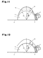
- Fig. 11 shows a radio wave lens antenna device of which the reflection plate 2 is arranged substantially parallel to the ground.
- the first cover 5 covers the entire lens 1 and has an upper portion inclined at an angle that is greater than the inclination angle of the upper portion of the lens 1.
- the first cover 5 functions as the ice-snow-water resistant means.
- An opening 14 between the first cover 5 and the lens 1 may be hollow. However, it is preferable that the opening 14 be filled with an olefin resin foam having a high foaming ratio and a dielectric constant that is as close as possible to 1.
- the inclination angle of the surface of the first cover 5 be greater than the inclination angle of the lens.
- R 1 represents the distance from the lens center to the first cover 5 at a position where the angle from the reflection plate 2 is ⁇ 1
- R 2 represents the distance from the lens center to the first cover 5 at a position where the angle from the reflection plate 2 is ⁇ 2
- the first cover 5 be shaped so as to satisfy the condition of R 1 > R 2 > R when ⁇ 2 > ⁇ 1 and ⁇ 2 ⁇ nR/2 are fulfilled. In such a case, the first cover 5 would have a superior water dispersing property.
- the radio wave lens antenna device shown in Fig. 12 is arranged on the ground in a state in which the reflection plate 2 is substantially horizontal.
- An aspheric second cover 12 covers part of the antenna device.
- the surface of the second cover 12 is inclined at an angle that is greater than the inclination angle of the surface of the first cover 5.
- the second cover 12 functions as the ice-snow-water resistant means.
- the inclination angle of the outer surface of the second cover 12 be greater than the inclination angle of an upper portion of the lens.
- R 1 represents the distance from the lens center to the second cover 12 at a position where the angle from the reflection plate 2 is ⁇ 1
- R 2 represents the distance from the lens center to the second cover 12 at a position where the angle from the reflection plate 2 is ⁇ 2
- the second cover 12 be shaped so as to satisfy the condition of R 1 > R 2 > R when ⁇ 2 > ⁇ 1 and ⁇ 2 ⁇ nR/2 are fulfilled.
- the reflection plate 2 is arranged substantially orthogonal to the ground.
- a third cover 15 is arranged between the antenna elements 3 and a portion of the lens surface (first cover 5) facing toward the antenna elements 3.
- the third cover 15 functions as the ice-snow-water resistant means.
- the third cover 15 is only required to be located above lines that connect the antenna elements 3 to the center of the lens 1.
- the shape is not particularly specified, it is preferable that the third cover 15 be tubular.
- the third cover 15 may also be employed in an antenna device in which the reflection plate 2 is arranged substantially parallel to the ground. Further, the third cover 15 may be used in combination with the first cover 5 and the second cover 6 or 12, which have been described above, to obtain synergistic effects.
- Figs. 14 and 15 each show a hood that functions as an ice-snow-water resistant means.
- These radio wave lens antenna devices include the elements illustrated in Fig. 1 .
- a hood 8 extends above the lens 1.
- the hood 8 is extended from the reflection plate 2 for a distance that is greater than the lens radius R so as to completely hide the lens 1 when viewed from above.
- the reflection plate 2 is inclined toward the front so that the upper end of the reflection plate 2 is located frontward from the lens 1.
- the reflection plate 2 functions as a hood to protect the lens 1 from rain and snow. This structure is meritorious in that it obtains the advantages of the invention without the need for special components.
- Figs. 16 to 18 each show a radio wave lens antenna device including a semispherical cover 5A (which may be identical to the afore-mentioned first cover).
- a barrier 9 is arranged on the surface of the cover 5A to function as an ice-snow-water resistant means.
- the radio wave lens antenna device includes the semispherical cover 5A so as to cover and protect the lens 1.
- the barrier 9 is arranged on the outer surface of the semispherical cover 5.
- the barrier 9 is located above lines connecting the antenna elements 3 to the center of the lens 1 and extends laterally over a predetermined length.
- the portion of the cover surface corresponding to the antenna elements 3 is in a region in which radio waves travel toward the antenna elements.
- the barrier 9 is arranged on the outer surface of the semispherical cover 5A to block the path of running water.
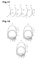
- the barrier 9 may include a recess 9a as shown in Fig. 17(a) , a projection 9b as shown in Figs. 17(b) and 17(c) , or a step 9c formed in the outer surface of the semispherical cover 5A as shown in Figs. 17(d) and 17(e) .
- Each barrier 9 has a predetermined width.
- the portion of the barrier 9 facing toward the antenna elements 3 is located at a high position from the ground and that the barrier 9 gradually becomes lower toward the lateral ends. This effectively guides water to a region that does not affect the reception of radio waves.
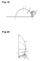
- the barrier 13 is arranged on the outer surface of the semispherical first cover 5 to prevent water from running toward a portion of the cover that corresponds to the antenna elements 3. In this manner, the barrier is effective not only when the reflection plate 2 is arranged orthogonal to the ground but also when the reflection plate 2 is arranged parallel to the ground.
- Fig. 20 shows a radio wave lens antenna device that includes the second cover 6 of Fig. 3 and the barrier 9 of Fig. 16 .
- This radio wave lens antenna device synergetically obtains the effect of the second cover 6, which prevents rain water and melted snow from collecting, and the effect of the barrier 9, which prevents water from running to a portion facing toward the antenna elements 3.
- this structure is effective for drastically decreasing the attenuation of radio waves when rain falls and snow melts.
- a cover surface that is water-repellant would be one effective example of a snow-ice-water resistant means that prevents the collection of rain water and melted snow.
- a water repelling treatment When the first cover 5 or the second cover 6 (or 12) undergoes a water repelling treatment, water comes into contact with the cover at a large angle. This repels the water so that the water does not collect on the cover surface. It is especially preferable that a water repelling treatment be carried out on the second cover 6 (or 12), which has a large inclination, since such a structure would be effective for preventing the collection of water.
- a hydrophilic treatment is carried out on the top of the first cover 5 to define a hydrophilic portion 10
- a water repelling treatment is carried out on the upper sloped surface of the first cover 5 excluding the top to define a hydrophobic portion 11.
- a hydrophilic treatment is carried out on only the top portion to prevent the collection of water.
- Fig. 22 shows an example in which a coating layer, or a so-called “sea-island structure", is formed on the surface of the first cover 5 by a hydrophilic coating that includes small hydrophobic coatings.
- a hydrophilic coating that includes small hydrophobic coatings.
- water is repelled by hydrophobic portions 11 (island portions), which are formed by the hydrophobic coatings, and runs along hydrophilic portions 10 (sea portions). This prevents the collection of rainwater and melted ice and snow.
- the hydrophobic portions 11 be small and have a diameter of 1 to 5 mm.
- the area ratio of the hydrophobic portions 11 and hydrophilic portions 10 be such that the area of the hydrophobic portions 11 be greater than the area of the hydrophilic portions 10.
- a water repelling treatment may be performed on the barriers 9 shown in Figs. 17 and 18 at portions where the water dispersing property should be especially increased to improve the hydrophobic property.
- a water repelling treatment and hydrophilic treatment are normally carried out by the application of a water repellant or hydrophilic coating.
- the present invention is not limited in such a manner and other surface modification treatments may be performed.
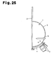
- the above described ice-snow-water resistance means may be used in combination, for example, as shown in Figs. 23 to 25 .
- radio wave lens antenna devices (examples and comparative examples) of the specifications shown in table 1 were prepared.
- the measurement system shown in Fig. 26 was used to measure the signal reception sensitivity (C/N) of the antenna devices every ten minutes in rain or snow. Normally, images cannot be generated on a TV display when C/N ⁇ 6 is satisfied. Thus, the time in which C/N ⁇ 6 was satisfied was checked to obtain the ratio relative to the time during which C/N ⁇ 6 was satisfied.
- Table 1 As apparent from table 1, in the examples to which the present invention was applied, the time during which radio wave disturbance occurred was shorter (the time during which images were generate was longer) than the comparative examples.
Landscapes
- Details Of Aerials (AREA)
- Aerials With Secondary Devices (AREA)
Abstract
Description
- The present invention relates to a radio wave lens antenna device that uses a Luneburg lens, and more particularly, to a radio wave lens antenna device that prevents the signal reception sensitivity from being lowered when rain falls or snow melts.
- It is anticipated that a radio wave lens antenna using a Luneburg lens can be employed as a multibeam-applicable antenna device enabling simultaneous communication with a plurality of communication peers. Further, such radio wave lens antennas have become able to take the place of parabolic antennas as geostationary satellite antenna devices.
- A Luneburg lens, which is formed by a dielectric, basically has a spherical shape. However, to miniaturize the radio wave lens, a semispherical Luneburg lens may be used in combination with a radio wave reflection plate (hereinafter, simply referred to as the reflection plate), which is larger than the diameter of the semispherical Luneburg lens, to form a radio wave lens having functions equivalent to those of a spherical Luneburg lens. Such an antenna device, which is combined with a reflection plate, may be arranged anywhere facing toward a target geostationary satellite with the reflection plate held in an erected state. For example, the antenna device may be arranged on the wall surface of a building or on the fence of a veranda. The antenna device may also be arranged on the roof of a building with the reflection plate being parallel to the ground. Thus, the antenna device has a high level of freedom of arrangement.
- In an antenna device that uses a Luneburg lens, a water resistant cover covers the outer surface of the lens. For example,
Patent Publication 1, which is listed below, discloses a semispherical radome formed integrally with a Luneburg lens. Further,Patent Publication 2, which is listed below, discloses a radome that covers an entire antenna device, which includes an antenna element. Additionally,Patent Publication 3, which is listed below, discloses a semispherical cover that covers a semispherical lens. - In this manner, a radome or semispherical cover covers the lens. Thus, there is particularly no problem with durability even when wet due to rain. However, when the rain that falls during usage collects on the lens or runs off the lens surface (outer surface of a surface protection layer), the attenuation C/N amount (power ratio of signal and noise) increases and lowers the signal reception sensitivity of radio waves. Further, when snow on the lens or ice on the lens melts, water runs off the surface of the lens. This also lowers the signal reception sensitivity of radio waves.
- Consideration has not been made for such a problem in the radio wave lens antenna devices of the prior art. Thus, there is a tendency for the signal reception sensitivity to become low. Further, when covering the entire antenna device with a radome, the thickness of the radome must be increased to ensure the required strength. As a result, the radome adversely affects the electrical properties, increases the size and weight, and raises costs.
- Patent Publication 1: Japanese Laid-Open Patent Publication No.
50-116259 - Patent Publication 2: Japanese Laid-Open Patent Publication No.
2000-183645 - Patent Publication 3: Japanese Laid-Open Patent Publication No.
2002-232230 - Patent Publication 4: Japanese Laid-Open Patent Publication No.
2004-282718 -
Patent Publication 4, which is listed above, describes an example of a geostationary satellite antenna device that uses a Luneburg lens. This antenna device is extremely superior when used as an antenna that receives radio waves from a geostationary satellite. However, when rain falls or snow melts, the antenna device is easily affected by water that collects on or runs off the Luneburg lens. Thus, there is a tendency for the signal reception sensitivity to become lower. - It is an object of the present invention to provide a radio wave lens antenna device that improves reliability by preventing rainwater and melting snow from lowering the signal reception sensitivity.
- To achieve, the above-discussed problem, in the present invention, a radio wave lens antenna device includes a semispherical Luneburg lens, a radio wave reflection plate lying along a bisectional surface of a sphere of the lens and having a size that is greater than the lens diameter, an antenna element, and a holder holding the antenna element. The radio wave lens antenna device includes an ice-snow-water resistant means which prevents rain, snow, and ice from collecting on a surface of the Luneburg lens and prevents water from running off the Luneburg lens.
- A specific example of the ice-snow-water resistant means is a cover which covers part of the radio wave lens antenna device. A preferred example of the cover covers the entire Luneburg lens in a state in which the reflection plate is erected on the ground and includes an upper portion inclined at an angle that is greater than an inclination angle of an upper portion of the Luneburg lens or covers an upper portion of the Luneburg lens in a state in which the reflection plate is parallel to the ground and includes a surface inclined at an angle that is greater than an inclination angle of the surface of the Luneburg lens. The inclination angle of the cover surface and inclination angle of the lens surface are compared based on the inclination of an extension of a line connecting a point on the semispherical surface of the lens to the lens center at a point where the extension intersects the cover (the angle of inclination relative to the ground at the surface contacting each point of comparison).
- Further, the cover includes a first cover, which covers the Luneburg lens in a state in which the reflection plate is erected on the ground, and a second cover, which covers an upper portion of the first cover, with the second cover having an upper portion inclined at an angle that is greater than an inclination angle of the upper portion of the first cover. In this case, it is preferred that the second cover has a lower end, which is separated from the lens and lower than the center of the lens. The inclination angle of the second cover surface and inclination angle of the first cover surface are compared based on the inclination of an extension of a line connecting a point on the first cover surface to the lens center at a point where the extension intersects the second cover (the angle of inclination relative to the ground at the surface contacting each point of comparison).
- The cover includes a first semispherical cover, which covers the Luneburg lens in a state in which the reflection plate is parallel to the ground, and a second cover, which covers an upper portion of the first cover, with the second cover having an upper portion inclined at an angle that is greater than an inclination angle of the upper portion of the first cover. This can be used in an antenna device that arranges the reflection plate parallel to the ground.
- The ice-snow-water resistant means includes a barrier formed on a surface of a cover covering the Luneburg lens, with the barrier being located above a line connecting the antenna lens and the lens center and extended laterally within a predetermined range. In this case, the barrier includes one of a recess, a projection, and a step. It is preferred that the barrier is located at a position that is above a portion of the cover surface facing toward the antenna element and high from the ground, and the barrier becomes gradually lower toward its two ends. It is also preferred that the barrier has a surface that undergoes a water repelling treatment.
- The ice-snow-rain resistant means may include a cover arranged between the antenna element and the Luneburg lens to cover the antenna device and a surface of the Luneburg lens at a region facing toward the antenna lens.
- The ice-snow-water resistant means may include a hood arranged above the Luneburg lens and extending outward from the radius of the Luneburg lens in a state in which the reflection plate is erected on the ground. The reflection plate may be inclined toward the front from a position at which it is erected orthogonally to the ground so that the inclined reflection plate also functions as the hood.
- The following are examples of the ice-snow-water resistant means:
- a cover that covers part of the antenna device and has a surface that has undergone one or both of a water repelling treatment and a hydrophilic treatment;
- a semispherical cover that covers the Luneburg lens, with the cover including a top portion that has undergone a hydrophilic treatment and an upper portion excluding the top portion that has undergone a water-repelling treatment;
- a cover that covers part of the antenna device, with the cover including a surface that has undergone a hydrophilic treatment and a water repelling treatment so that island-like hydrophobic portions are scattered in a hydrophilic portion, wherein the area of the hydrophobic portion is preferably greater than the area of the hydrophilic portions; and
- the cover is formed from synthetic resin, rubber, fibers, glass or a composite of these materials. A foam of synthetic resin, rubber, and glass may be used.
- The radio wave lens antenna device according to the present invention includes a cover that covers part of the antenna device to function as an ice-snow, water resistant means that prevents rain, snow, and ice from collecting on the surface of the Luneburg lens or water from running frontward to the antenna element. This prevents rain water and melted snow from collecting on the surface of the lens. A radio wave lens antenna device that includes a barrier arranged on the surface of the cover does not function to prevent the collection of rain, snow, and ice. However, rainwater or melted snow that runs along the surface of the cover is guided to the barrier or stopped by the barrier and thus does not run through a path of the radio waves that travel toward the antenna element. Accordingly, the present invention reduces the collected rainwater, snow, and ice. Further, rainwater and melted snow and ice do not run toward a position that greatly affects the signal reception sensitivity of the antenna, that is, to a position on the lens surface corresponding to the antenna element. Thus, the signal reception sensitivity is subtly lowered by running water.
-
-
Fig. 1 is a schematic perspective view showing a radio wave lens antenna device to which the present invention is applied; -
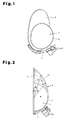
Fig. 2 is a side view showing one example of a radio wave lens antenna device according to the present invention; -
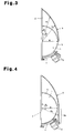
Fig. 3 is a partially cutaway side view showing another embodiment; -
Fig. 4 is a partially cutaway side view showing a further embodiment; -
Fig. 5 is a side view showing a further embodiment; -
Fig. 6 is a partially cutaway side view showing a further embodiment; -
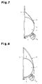
Fig. 7 is a partially cutaway side view showing a further embodiment; -
Fig. 8 is a partially cutaway side view showing a further embodiment; -
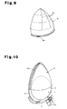
Fig. 9 is a perspective view showing one example of a ribbed cover; -
Fig. 10 is a perspective view showing a further embodiment; -
Fig. 11 is a side view showing a further embodiment; -
Fig. 12 is a partially cutaway side view showing a further embodiment; -
Fig. 13 is a side view showing a further embodiment; -
Fig. 14 is a side view showing a further embodiment; -
Fig. 15 is a side view showing a further embodiment; -
Fig. 16 is a side view showing a further embodiment; -
Figs. 17(a) to 17(e) are diagrams showing the cross-sectional shape of barriers; -
Figs. 18(a) to 18(c) are front views showing the installed state of the barriers; -
Fig. 19 is a side view showing a further embodiment; -
Fig. 20 is a side view showing a further embodiment; -
Fig. 21 is a perspective view showing a further embodiment; -
Fig. 22 is a perspective view showing a further embodiment; -
Fig. 23 is a perspective view showing a further embodiment; -
Fig. 24 is a side view showing a further embodiment; -
Fig. 25 is a side view showing a further embodiment; and -
Fig. 26 is a diagram showing a measurement system used in an experiment for checking the effects. -
- 1
- Luneburg lens
- 2
- reflection plate
- 3
- antenna element
- 4
- holder
- 5, 5A
- first cover
- 6, 12
- second cover
- 6a
- skirt
- 6b
- flange
- 6c
- vertical rib
- 6d
- horizontal rib
- 7
- cover (radome)
- 8
- hood
- 9, 13
- barrier
- 9a
- recess
- 9b
- projection
- 9c
- step
- 10
- hydrophilic portion
- 11
- hydrophobic portion
- 14
- opening
- 15
- third cover
- One embodiment of the present invention will now be discussed with reference to the accompanying drawings. A radio wave lens antenna device according to the present invention includes a semispherical Luneburg lens (hereinafter, simply referred to as the lens) 1, which is shown in
Fig. 1 , a radio wave reflection plate (hereinafter, simply referred to as the reflection plate) 2,antenna elements 3, and aholder 4. Thereflection plate 2 lies along a bisectional surface of the sphere of thelens 1 and is larger than the diameter of the lens. Theantenna elements 3 are arranged at a focal point of the lens. Theholder 4 holds thelens elements 3. - The
lens 1 is formed by a dielectric, has an internal dielectric constant that substantially varies between 2 to 1 from the center toward the outer side, and has a focal point located near the spherical surface. A semisphericalfirst cover 5 is formed from resin, has a smooth surface, and covers the periphery of thelens 1 to protect thelens 1. - The
reflection plate 2 has longitudinal and lateral dimensions that are greater than the diameter of thelens 1. The radio wave lens antenna of the present invention may be used in states in which thereflection plate 2 is substantially orthogonal to the ground, thereflection plate 2 is forwardly inclined to the ground, and thereflection plate 2 is substantially parallel to the ground. In any of these cases, theantenna elements 3 are arranged at a position where radio waves from a target geostationary satellite are converged (focal portion). - A low-noise block converter (LNB) is used for each of the
antenna elements 3. Theantenna elements 3 may be a horn antenna or a cylindrical antenna having a front portion from which a dielectric is suspended. Further, an arm enabling adjustment of the element positions is used as theholder 4. - The antenna device of
Fig. 1 includes an ice-snow-water resistant means, which is the feature of the present invention. Examples of the ice-snow-water resistant means are shown inFigs. 2 to 25 . In the radio wave lens antenna device shown inFig. 2 , thereflection plate 2 is arranged substantially orthogonal to the ground. Thefirst cover 5 covers theentire lens 1. The upper portion of the cover is inclined at an angle that is greater than the inclination angle at an upper portion of thelens 1. Thefirst cover 5 functions as the ice-snow-water resistant means. - An
opening 14 between thefirst cover 5 and thelens 1 may be hollow. However, it is preferable that theopening 14 be filled with an olefin resin foam having a high foaming ratio and a dielectric constant that is as close as possible to 1. - It is preferable that the inclination angle of the surface of the
first cover 5 be greater than the inclination angle of the lens. InFig. 2 , when R represents the lens diameter, R1 represents the distance from the lens center to thefirst cover 5 at a position where the angle from thereflection plate 2 is θ1, and R2 represents the distance from the lens center to thefirst cover 5 at a position where the angle from thereflection plate 2 is θ2, it is preferable that thefirst cover 5 be shaped so as to satisfy the condition of R1 > R2 > R when θ2 > θ1 and θ2 ≤ nR/2 are fulfilled. - In the radio wave lens antenna device shown in
Fig. 3 , thereflection plate 2 is arranged substantially orthogonal to the ground. An asphericsecond cover 6 covers part of the antenna device. The surface of thesecond cover 6 is inclined at an angle that is greater than the inclination angle of the surface of thefirst cover 5. Thesecond cover 6 functions as the ice-snow-water resistant means. - It is preferable that the inclination angle of the outer surface of the
second cover 6 be greater than the inclination angle of an upper portion of the lens. InFig. 3 , when R represents the lens diameter, R1 represents the distance from the lens center to thesecond cover 6 at a position where the angle from thereflection plate 2 is θ1, and R2 represents the distance from the lens center to thesecond cover 6 at a position where the angle from thereflection plate 2 is θ2, it is preferable that thesecond cover 6 be shaped so as to satisfy the condition of R1 > R2 > R when θ2 > θ1 and θ2 ≤ nR/2 are fulfilled. - As shown in
Fig. 4 , the lower end of thesecond cover 6 may be extended to a position separated from thelens 1 and located lower than the lens center (i.e., askirt 6a may be formed). This prevents rainwater and melting snow from being collected. In addition, water droplets subtly reach the lower portion of thefirst cover 5. Thus, water does not run along the path of radio waves directed toward theantenna elements 3, and the radio waves travel without any interference. - Further, in the antenna device shown in
Fig. 3 , thesecond cover 6 may have a lower end that comes into contact with the surface of thelens 1 as shown inFig. 5 or a lower end that is separated from the lens so as to form a gap g as shown inFig. 6 . When in contact with the lens, the wind resistance is increased. When separated from the lens, water that runs along thesecond cover 6 does not reach the surface of the lens 1 (first cover 5). - It is preferred that the
first cover 5 have a thickness of 2 mm or less and more preferred that the thickness be 1 mm or less so as to prevent the electrical properties of the antenna from being adversely affected. - It is preferred that the gap between the
first cover 5 and thelens 1 be small to decrease electrical losses and ensure the required strength. Thefirst cover 5 andlens 1 may be adhered or fused to each other. - The surface of the
first cover 5 may be coated. - The
second cover 6 is formed from a material that transmits radio waves, such as synthetic resin, rubber, fiber, glass or a composite of these materials (e.g., a laminated body). It is preferred that a polyolefin resin, the type of which is not particularly designated, having a low electric tan δ be used. - The
second cover 6 does not have to be a molded product. Thesecond cover 6 may be a thin sheet-like cover or a thin fabric that does not have a shape retaining property. Such a sheet-like cover or fabric is flapped by winds. This easily disperses water drops collected on the surface of the cover. Thus, the cover has a superior water dispersing property. When using a transparent resin such as an acrylic resin or polycarbonate resin, the size of the cover may be reduced. - As shown in
Fig. 7 , thesecond cover 6 may have an upper end, which is lower than the upper end of thereflection plate 2. - In the same manner as the
first cover 5, it is preferred that thesecond cover 6 have a thickness of 2 mm or less and more preferred that the thickness be 1 mm or less so as to prevent the electrical properties of the antenna from being adversely affected. Further, the thickness does not have to be uniform and may vary as shown inFig. 8 . By varying the thickness, the electrical properties of the antenna device are prevented from being adversely affected by the thickness, while ensuring the required strength. As shown inFig. 9 ,vertical ribs 6c and horizontal ribs 6d may be added to decrease the thickness of thesecond cover 6 and reduce the material costs and weight of the cover. The vertical ribs 6d shown in the drawing are formed by bent sections. However, the ribs may be molded. - The rim of the
second cover 6 that comes into contact with thereflection plate 2 may be sealed to prevent the entry of rainwater. A double-sided adhesive tape may be used to seal the rim. Further, the rim may be fastened to thereflection plate 2 by screws or bolts to prevent displacement and increase reliability. Anattachment flange 6b such as that shown inFig. 10 may be used so that thesecond cover 6 is attached to thereflection plate 2 with screws or bolts in a reliable manner. Resin bolts may be used so that thesecond cover 6 can be freely detached from thereflection plate 2. -
Fig. 11 shows a radio wave lens antenna device of which thereflection plate 2 is arranged substantially parallel to the ground. In this device, thefirst cover 5 covers theentire lens 1 and has an upper portion inclined at an angle that is greater than the inclination angle of the upper portion of thelens 1. Thefirst cover 5 functions as the ice-snow-water resistant means. - An
opening 14 between thefirst cover 5 and thelens 1 may be hollow. However, it is preferable that theopening 14 be filled with an olefin resin foam having a high foaming ratio and a dielectric constant that is as close as possible to 1. - It is preferable that the inclination angle of the surface of the
first cover 5 be greater than the inclination angle of the lens. InFig. 2 , when R represents the lens diameter, R1 represents the distance from the lens center to thefirst cover 5 at a position where the angle from thereflection plate 2 is θ1, and R2 represents the distance from the lens center to thefirst cover 5 at a position where the angle from thereflection plate 2 is θ2, it is preferable that thefirst cover 5 be shaped so as to satisfy the condition of R1 > R2 > R when θ2 > θ1 and θ2 ≤ nR/2 are fulfilled. In such a case, thefirst cover 5 would have a superior water dispersing property. - The radio wave lens antenna device shown in
Fig. 12 is arranged on the ground in a state in which thereflection plate 2 is substantially horizontal. An asphericsecond cover 12 covers part of the antenna device. The surface of thesecond cover 12 is inclined at an angle that is greater than the inclination angle of the surface of thefirst cover 5. Thesecond cover 12 functions as the ice-snow-water resistant means. - It is preferable that the inclination angle of the outer surface of the
second cover 12 be greater than the inclination angle of an upper portion of the lens. InFig. 12 , when R represents the lens diameter, R1 represents the distance from the lens center to thesecond cover 12 at a position where the angle from thereflection plate 2 is θ1, and R2 represents the distance from the lens center to thesecond cover 12 at a position where the angle from thereflection plate 2 is θ2, it is preferable that thesecond cover 12 be shaped so as to satisfy the condition of R1 > R2 > R when θ2 > θ1 and θ2 ≤ nR/2 are fulfilled. - In the radio wave lens antenna device shown in
Fig. 13 , thereflection plate 2 is arranged substantially orthogonal to the ground. Athird cover 15 is arranged between theantenna elements 3 and a portion of the lens surface (first cover 5) facing toward theantenna elements 3. Thethird cover 15 functions as the ice-snow-water resistant means. Thethird cover 15 is only required to be located above lines that connect theantenna elements 3 to the center of thelens 1. Although the shape is not particularly specified, it is preferable that thethird cover 15 be tubular. Thethird cover 15 may also be employed in an antenna device in which thereflection plate 2 is arranged substantially parallel to the ground. Further, thethird cover 15 may be used in combination with thefirst cover 5 and thesecond cover -
Figs. 14 and15 each show a hood that functions as an ice-snow-water resistant means. These radio wave lens antenna devices include the elements illustrated inFig. 1 . In the antenna device ofFig. 14 , in a state in which thereflection plate 2 is arranged substantially orthogonal to the ground, a hood 8 extends above thelens 1. The hood 8 is extended from thereflection plate 2 for a distance that is greater than the lens radius R so as to completely hide thelens 1 when viewed from above. - In the radio antenna device of
Fig. 15 , thereflection plate 2 is inclined toward the front so that the upper end of thereflection plate 2 is located frontward from thelens 1. Thus, thereflection plate 2 functions as a hood to protect thelens 1 from rain and snow. This structure is meritorious in that it obtains the advantages of the invention without the need for special components. -
Figs. 16 to 18 each show a radio wave lens antenna device including asemispherical cover 5A (which may be identical to the afore-mentioned first cover). Abarrier 9 is arranged on the surface of thecover 5A to function as an ice-snow-water resistant means. The radio wave lens antenna device includes thesemispherical cover 5A so as to cover and protect thelens 1. Thebarrier 9 is arranged on the outer surface of thesemispherical cover 5. Thebarrier 9 is located above lines connecting theantenna elements 3 to the center of thelens 1 and extends laterally over a predetermined length. - The portion of the cover surface corresponding to the
antenna elements 3 is in a region in which radio waves travel toward the antenna elements. Thus, by preventing water from running through this region, the attenuation of the radio waves that would be caused by such water can be decreased. To achieve this object, thebarrier 9 is arranged on the outer surface of thesemispherical cover 5A to block the path of running water. Thebarrier 9 may include arecess 9a as shown inFig. 17(a) , aprojection 9b as shown inFigs. 17(b) and 17(c) , or astep 9c formed in the outer surface of thesemispherical cover 5A as shown inFigs. 17(d) and 17(e) . Eachbarrier 9 has a predetermined width. - As shown in
Fig. 18 , it is preferable that the portion of thebarrier 9 facing toward theantenna elements 3 is located at a high position from the ground and that thebarrier 9 gradually becomes lower toward the lateral ends. This effectively guides water to a region that does not affect the reception of radio waves. - In the radio wave lens antenna device of
Fig. 19 , thebarrier 13 is arranged on the outer surface of the semisphericalfirst cover 5 to prevent water from running toward a portion of the cover that corresponds to theantenna elements 3. In this manner, the barrier is effective not only when thereflection plate 2 is arranged orthogonal to the ground but also when thereflection plate 2 is arranged parallel to the ground. -
Fig. 20 shows a radio wave lens antenna device that includes thesecond cover 6 ofFig. 3 and thebarrier 9 ofFig. 16 . This radio wave lens antenna device synergetically obtains the effect of thesecond cover 6, which prevents rain water and melted snow from collecting, and the effect of thebarrier 9, which prevents water from running to a portion facing toward theantenna elements 3. Thus, this structure is effective for drastically decreasing the attenuation of radio waves when rain falls and snow melts. - A cover surface that is water-repellant would be one effective example of a snow-ice-water resistant means that prevents the collection of rain water and melted snow. When the
first cover 5 or the second cover 6 (or 12) undergoes a water repelling treatment, water comes into contact with the cover at a large angle. This repels the water so that the water does not collect on the cover surface. It is especially preferable that a water repelling treatment be carried out on the second cover 6 (or 12), which has a large inclination, since such a structure would be effective for preventing the collection of water. - In
Fig. 21 , a hydrophilic treatment is carried out on the top of thefirst cover 5 to define ahydrophilic portion 10, and a water repelling treatment is carried out on the upper sloped surface of thefirst cover 5 excluding the top to define ahydrophobic portion 11. When the surface that is closer to the ground undergoes a water repelling treatment, repelled water does not run and forms water droplets that collect on the cover. This is counterproductive. Thus, a hydrophilic treatment is carried out on only the top portion to prevent the collection of water. -
Fig. 22 shows an example in which a coating layer, or a so-called "sea-island structure", is formed on the surface of thefirst cover 5 by a hydrophilic coating that includes small hydrophobic coatings. In such a structure, water is repelled by hydrophobic portions 11 (island portions), which are formed by the hydrophobic coatings, and runs along hydrophilic portions 10 (sea portions). This prevents the collection of rainwater and melted ice and snow. It is preferred that thehydrophobic portions 11 be small and have a diameter of 1 to 5 mm. Further, since thehydrophilic portions 10 temporarily form a water film, it is preferred that the area ratio of thehydrophobic portions 11 andhydrophilic portions 10 be such that the area of thehydrophobic portions 11 be greater than the area of thehydrophilic portions 10. - A water repelling treatment may be performed on the
barriers 9 shown inFigs. 17 and 18 at portions where the water dispersing property should be especially increased to improve the hydrophobic property. - A water repelling treatment and hydrophilic treatment are normally carried out by the application of a water repellant or hydrophilic coating. However, the present invention is not limited in such a manner and other surface modification treatments may be performed.
- The above described ice-snow-water resistance means may be used in combination, for example, as shown in
Figs. 23 to 25 . - An experiment that was conducted to check the effects of the present invention will now be described. In the experiment, radio wave lens antenna devices (examples and comparative examples) of the specifications shown in table 1 were prepared. The measurement system shown in
Fig. 26 was used to measure the signal reception sensitivity (C/N) of the antenna devices every ten minutes in rain or snow. Normally, images cannot be generated on a TV display when C/N < 6 is satisfied. Thus, the time in which C/N ≥ 6 was satisfied was checked to obtain the ratio relative to the time during which C/N < 6 was satisfied. The results are shown in table 1. As apparent from table 1, in the examples to which the present invention was applied, the time during which radio wave disturbance occurred was shorter (the time during which images were generate was longer) than the comparative examples. Accordingly, it is apparent that the ice-snow-water prevention means is effective for preventing rain and snow from lowering the signal reception sensitivity.[Table 1] Antenna Shape Signal Reception Property Outer Appearance Configuration 1st Cover 2nd Cover Element Cover Step Hood - Total Evaluation Time (H) Rain /Snow Image Generated Time (H) Ratio of Image-Generated Time (%) Example 1 Fig. 2 Vertical Nut-Shaped - - - - - 2304 Rain 2286 99.2 Comparative Example 1 Fig. 1 Vertical Semispherical - - - - - 2304 Rain 2212 96.0 Example 2 Fig. 3 Vertical Semispherical Length: Lens Center - - - - 2304 Rain 2288 99.3 Example 3 Fig. 4 Vertical Semispherical Length: Downward from Lens Center - - - - 2304 Rain 2297 99.7 Example 4 Fig. 20 Vertical Semispherical Length: Lens Center - Projection - - 2304 Rain 2299 99.8 Example 5 Water Repelling Treatment on Barrier 9 ofFig. 4 Vertical Semispherical Length: Downward from Lens Center - - - 2nd Cover Water Repelling Treatment 2304 Rain 2302 99.9 Example 6 Fig. 11 Horizontal Long-Hat-Shaped - - - - - 2304 Rain 2279 98.9 Example 7 Fig. 23 Horizontal Semispherical Long-Hat-Shaped - Projection - - 2304 Rain 2286 99.2 Comparative Example 2 Fig.24 Horizontal Semispherical - - - - - 2304 Rain 2221 92.0 Example 8 Fig. 25 Vertical Semispherical - - Projection Lateral Line - - 2304 Rain 2261 98.1 Example 9 Fig. 16 . Shape ofBarrier 9 as inFig. 17b Vertical Semispherical - - Projection - - 2304 Rain 2274 98.7 Example 10 Fig. 16 , Shape ofBarrier 9 as inFig. 17e Vertical Semispherical - - L - - 2304 Rain 2272 98.6 Example 11 Fig. 16 . Shape ofBarrier 9 as inFig. 17d Vertical Semispherical - - Reversed L - - 2304 Rain 2275 98.7 Example 12 Fig. 13 Vertical Semispherical - Element Cover - - - 2304 Rain 2276 98.8 Example 13 Fig. 16 , Shape ofBarrier 9 as inFig. 17b , Water Repelling Treatment onBarrier 9Vertical Semispherical - - Projection - Barrier 9 Water Repelling Treatment2304 Rain 2283 99.1 Example 14 Fig. 15 Vertical Semispherical - - - Inclined Reflection Plate - 2304 Rain 2280 99.0 Example 15 Fig. 14 Vertical Semispherical - - - Hood - 2304 Rain 2281 99.0 Example 16 Fig. 1 , Water Repelling Treatment onEntire First Cover 5Vertical Semispherical - - - - Entirely Water Repellant 2304 Rain 2280 99.0 Example 17 Fig. 21 Vertical Semispherical - - - - Top Hydrophilic, Remainder Water Repellant 2304 Rain 2288 99.3 Example 18 Fig. 22 Vertical Semispherical - - - - Sea-Island 2304 Rain 2290 99.4 Example 19 Fig. 2 Vertical Nut-Shaped - - - - - 3648 Snow 3613 99.0 Comparative Example 3 Fig. 1 Vertical Semispherical - - - - 3648 Snow 3457 95.0 Example 20 Fig. 4 Vertical Semispherical Length: Downward from Lens Center - - - - 3648 Snow 3640 99.8 Example 21 Fig. 16 , Shape ofBarrier 9 as inFig. 17b Vertical Semispherical - - - Projection - 3648 Snow 3574 98.0 Example 22 Fig. 13 Vertical Semispherical - Element Cover - - - 3648 Snow 3583 98.2 Example 23 Fig. 15 Vertical Semispherical - - - Inclined Reflection Plate - 3648 Snow 3627 99.4 Example 24 Fig. 1 . Water Repelling Treatment onEntire First Cover 5Vertical Semispherical - - - - Entirely Water Repellant 3648 Snow 3603 98.8
Claims (19)
- A radio wave lens antenna device including a semispherical Luneburg lens, a radio wave reflection plate lying along a bisectional surface of a sphere of the lens and having a size that is greater than the lens diameter, an antenna element, and a holder holding the antenna element, the radio wave lens antenna device being characterized by:an ice-snow-water resistant means which prevents rain, snow, and ice from collecting on a surface of the Luneburg lens and prevents water from running off the Luneburg lens.
- The radio wave lens antenna device according to claim 1, wherein the ice-snow-water resistant means includes a cover which covers part of the radio wave lens antenna device.
- The radio wave lens antenna device according to claim 2, wherein the cover covers the entire Luneburg lens in a state in which the reflection plate is erected on the ground, and the cover includes an upper portion inclined at an angle that is greater than an inclination angle of an upper portion of the Luneburg lens.
- The radio wave lens antenna device according to claim 2, wherein the cover includes a first semispherical cover, which covers the Luneburg lens in a state in which the reflection plate is erected on the ground, and a second cover, which covers an upper portion of the first cover, with the second cover having an upper portion inclined at an angle that is greater than an inclination angle of the upper portion of the first cover.
- The radio wave lens antenna device according to claim 4, wherein the second cover has a lower end, which is separated from the lens and lower than the center of the lens.
- The radio wave lens antenna device according to claim 2, wherein the cover covers an upper portion of the Luneburg lens in a state in which the reflection plate is parallel to the ground, and the cover includes a surface inclined at an angle that is greater than an inclination angle of the surface of the Luneburg lens.
- The radio wave lens antenna device according to claim 2, wherein the cover includes a first semispherical cover, which covers the Luneburg lens in a state in which the reflection plate is parallel to the ground, and a second cover, which covers an upper portion of the first cover, with the second cover having an upper portion inclined at an angle that is greater than an inclination angle of the upper portion of the first cover.
- The radio wave lens antenna device according to claim 1, wherein the ice-snow-water resistant means includes a barrier formed on a surface of a cover covering the Luneburg lens, with the barrier being located above a line connecting the antenna element and the lens center and extended laterally within a predetermined range.
- The radio wave lens antenna device according to claim 8, wherein the barrier includes one of a recess, a projection, and a step.
- The radio wave lens antenna device according to claim 8, wherein the barrier is located at a position that is above a portion of the cover surface facing toward the antenna element and high from the ground, and the barrier becomes gradually lower toward its two ends.
- The radio wave lens antenna device according to claim 8, wherein the barrier has a surface that has undergone a water repelling treatment.
- The radio wave lens antenna device according to claim 1, wherein the ice-snow-rain resistant means includes a cover arranged between the antenna element and the Luneburg lens to cover the antenna element and a surface of the Luneburg lens at a region facing toward the antenna element.
- The radio wave lens antenna device according to claim 1, wherein the ice-snow-water resistant means includes a hood arranged above the Luneburg lens and extending outward from the radius of the Luneburg lens in a state in which the reflection plate is erected on the ground.
- The radio wave lens antenna device according to claim 13, wherein the reflection plate is inclined toward the front from a position at which it is erected orthogonally to the ground so that the inclined reflection plate also functions as the hood.
- The radio wave lens antenna device according to claim 1, wherein the ice-snow-water resistant means includes a cover that covers part of the antenna device and has a surface that has undergone one or both of a water repelling treatment and a hydrophilic treatment.
- The radio wave lens antenna device according to claim 15, wherein the ice-snow-water resistant means includes a semispherical cover that covers the Luneburg lens, with the cover including a top portion that has undergone a hydrophilic treatment and an upper portion excluding the top portion that has undergone a water-repelling treatment.
- The radio wave lens antenna device according to claim 15, wherein the ice-snow-water resistant means includes a cover that covers part of the antenna device, with the cover including a surface that has undergone a hydrophilic treatment and a water repelling treatment so that island-like hydrophobic portions are scattered in a hydrophilic portion.
- The radio wave lens antenna device according to claim 17, wherein the area of the hydrophobic portion is greater than the area of the hydrophilic portions.
- The radio wave lens antenna device according to any one of claims 2 to 18, wherein the cover is formed from synthetic resin, rubber, fibers, glass or a composite of these materials.
Applications Claiming Priority (1)
| Application Number | Priority Date | Filing Date | Title |
|---|---|---|---|
| PCT/JP2006/311419 WO2007141850A1 (en) | 2006-06-07 | 2006-06-07 | Radio wave lens antenna device |
Publications (1)
| Publication Number | Publication Date |
|---|---|
| EP2037531A1 true EP2037531A1 (en) | 2009-03-18 |
Family
ID=38801122
Family Applications (1)
| Application Number | Title | Priority Date | Filing Date |
|---|---|---|---|
| EP06757126A Withdrawn EP2037531A1 (en) | 2006-06-07 | 2006-06-07 | Radio wave lens antenna device |
Country Status (4)
| Country | Link |
|---|---|
| US (1) | US20100039339A1 (en) |
| EP (1) | EP2037531A1 (en) |
| CN (1) | CN101461091A (en) |
| WO (1) | WO2007141850A1 (en) |
Cited By (1)
| Publication number | Priority date | Publication date | Assignee | Title |
|---|---|---|---|---|
| CN102098066A (en) * | 2009-12-10 | 2011-06-15 | 夏普株式会社 | Millimeter wave reception device, mounting structure for millimeter wave reception device, and millimeter wave transmission/reception device |
Families Citing this family (159)
| Publication number | Priority date | Publication date | Assignee | Title |
|---|---|---|---|---|
| US8368552B2 (en) | 2009-12-22 | 2013-02-05 | At&T Intellectual Property I, L.P. | Manhole security device and methods thereof |
| CN102280709A (en) * | 2011-05-27 | 2011-12-14 | 京信通信系统(中国)有限公司 | Outer cover of broadband shaped antenna and microwave antenna |
| US9113347B2 (en) | 2012-12-05 | 2015-08-18 | At&T Intellectual Property I, Lp | Backhaul link for distributed antenna system |
| US10009065B2 (en) | 2012-12-05 | 2018-06-26 | At&T Intellectual Property I, L.P. | Backhaul link for distributed antenna system |
| US9999038B2 (en) | 2013-05-31 | 2018-06-12 | At&T Intellectual Property I, L.P. | Remote distributed antenna system |
| US9525524B2 (en) | 2013-05-31 | 2016-12-20 | At&T Intellectual Property I, L.P. | Remote distributed antenna system |
| US8897697B1 (en) | 2013-11-06 | 2014-11-25 | At&T Intellectual Property I, Lp | Millimeter-wave surface-wave communications |
| US9209902B2 (en) | 2013-12-10 | 2015-12-08 | At&T Intellectual Property I, L.P. | Quasi-optical coupler |
| JP6315423B2 (en) | 2014-06-04 | 2018-04-25 | パナソニックIpマネジメント株式会社 | Radio apparatus and radio system |
| US9692101B2 (en) | 2014-08-26 | 2017-06-27 | At&T Intellectual Property I, L.P. | Guided wave couplers for coupling electromagnetic waves between a waveguide surface and a surface of a wire |
| US9768833B2 (en) | 2014-09-15 | 2017-09-19 | At&T Intellectual Property I, L.P. | Method and apparatus for sensing a condition in a transmission medium of electromagnetic waves |
| US10063280B2 (en) | 2014-09-17 | 2018-08-28 | At&T Intellectual Property I, L.P. | Monitoring and mitigating conditions in a communication network |
| US9615269B2 (en) | 2014-10-02 | 2017-04-04 | At&T Intellectual Property I, L.P. | Method and apparatus that provides fault tolerance in a communication network |
| US9685992B2 (en) | 2014-10-03 | 2017-06-20 | At&T Intellectual Property I, L.P. | Circuit panel network and methods thereof |
| US9503189B2 (en) | 2014-10-10 | 2016-11-22 | At&T Intellectual Property I, L.P. | Method and apparatus for arranging communication sessions in a communication system |
| US9762289B2 (en) | 2014-10-14 | 2017-09-12 | At&T Intellectual Property I, L.P. | Method and apparatus for transmitting or receiving signals in a transportation system |
| US9973299B2 (en) | 2014-10-14 | 2018-05-15 | At&T Intellectual Property I, L.P. | Method and apparatus for adjusting a mode of communication in a communication network |
| US9627768B2 (en) | 2014-10-21 | 2017-04-18 | At&T Intellectual Property I, L.P. | Guided-wave transmission device with non-fundamental mode propagation and methods for use therewith |
| US9780834B2 (en) | 2014-10-21 | 2017-10-03 | At&T Intellectual Property I, L.P. | Method and apparatus for transmitting electromagnetic waves |
| US9520945B2 (en) | 2014-10-21 | 2016-12-13 | At&T Intellectual Property I, L.P. | Apparatus for providing communication services and methods thereof |
| US9577306B2 (en) | 2014-10-21 | 2017-02-21 | At&T Intellectual Property I, L.P. | Guided-wave transmission device and methods for use therewith |
| US9769020B2 (en) | 2014-10-21 | 2017-09-19 | At&T Intellectual Property I, L.P. | Method and apparatus for responding to events affecting communications in a communication network |
| US9312919B1 (en) | 2014-10-21 | 2016-04-12 | At&T Intellectual Property I, Lp | Transmission device with impairment compensation and methods for use therewith |
| US9653770B2 (en) | 2014-10-21 | 2017-05-16 | At&T Intellectual Property I, L.P. | Guided wave coupler, coupling module and methods for use therewith |
| US9954287B2 (en) | 2014-11-20 | 2018-04-24 | At&T Intellectual Property I, L.P. | Apparatus for converting wireless signals and electromagnetic waves and methods thereof |
| US9461706B1 (en) | 2015-07-31 | 2016-10-04 | At&T Intellectual Property I, Lp | Method and apparatus for exchanging communication signals |
| US9654173B2 (en) | 2014-11-20 | 2017-05-16 | At&T Intellectual Property I, L.P. | Apparatus for powering a communication device and methods thereof |
| US9680670B2 (en) | 2014-11-20 | 2017-06-13 | At&T Intellectual Property I, L.P. | Transmission device with channel equalization and control and methods for use therewith |
| US9997819B2 (en) | 2015-06-09 | 2018-06-12 | At&T Intellectual Property I, L.P. | Transmission medium and method for facilitating propagation of electromagnetic waves via a core |
| US9742462B2 (en) | 2014-12-04 | 2017-08-22 | At&T Intellectual Property I, L.P. | Transmission medium and communication interfaces and methods for use therewith |
| US9800327B2 (en) | 2014-11-20 | 2017-10-24 | At&T Intellectual Property I, L.P. | Apparatus for controlling operations of a communication device and methods thereof |
| US10009067B2 (en) | 2014-12-04 | 2018-06-26 | At&T Intellectual Property I, L.P. | Method and apparatus for configuring a communication interface |
| US9544006B2 (en) | 2014-11-20 | 2017-01-10 | At&T Intellectual Property I, L.P. | Transmission device with mode division multiplexing and methods for use therewith |
| US10340573B2 (en) | 2016-10-26 | 2019-07-02 | At&T Intellectual Property I, L.P. | Launcher with cylindrical coupling device and methods for use therewith |
| US10243784B2 (en) | 2014-11-20 | 2019-03-26 | At&T Intellectual Property I, L.P. | System for generating topology information and methods thereof |
| US10144036B2 (en) | 2015-01-30 | 2018-12-04 | At&T Intellectual Property I, L.P. | Method and apparatus for mitigating interference affecting a propagation of electromagnetic waves guided by a transmission medium |
| US9876570B2 (en) | 2015-02-20 | 2018-01-23 | At&T Intellectual Property I, Lp | Guided-wave transmission device with non-fundamental mode propagation and methods for use therewith |
| US9749013B2 (en) | 2015-03-17 | 2017-08-29 | At&T Intellectual Property I, L.P. | Method and apparatus for reducing attenuation of electromagnetic waves guided by a transmission medium |
| US10224981B2 (en) | 2015-04-24 | 2019-03-05 | At&T Intellectual Property I, Lp | Passive electrical coupling device and methods for use therewith |
| US9705561B2 (en) | 2015-04-24 | 2017-07-11 | At&T Intellectual Property I, L.P. | Directional coupling device and methods for use therewith |
| US9793954B2 (en) | 2015-04-28 | 2017-10-17 | At&T Intellectual Property I, L.P. | Magnetic coupling device and methods for use therewith |
| US9948354B2 (en) | 2015-04-28 | 2018-04-17 | At&T Intellectual Property I, L.P. | Magnetic coupling device with reflective plate and methods for use therewith |
| US9748626B2 (en) | 2015-05-14 | 2017-08-29 | At&T Intellectual Property I, L.P. | Plurality of cables having different cross-sectional shapes which are bundled together to form a transmission medium |
| US9490869B1 (en) | 2015-05-14 | 2016-11-08 | At&T Intellectual Property I, L.P. | Transmission medium having multiple cores and methods for use therewith |
| US9871282B2 (en) | 2015-05-14 | 2018-01-16 | At&T Intellectual Property I, L.P. | At least one transmission medium having a dielectric surface that is covered at least in part by a second dielectric |
| US10650940B2 (en) | 2015-05-15 | 2020-05-12 | At&T Intellectual Property I, L.P. | Transmission medium having a conductive material and methods for use therewith |
| US9917341B2 (en) | 2015-05-27 | 2018-03-13 | At&T Intellectual Property I, L.P. | Apparatus and method for launching electromagnetic waves and for modifying radial dimensions of the propagating electromagnetic waves |
| US9866309B2 (en) | 2015-06-03 | 2018-01-09 | At&T Intellectual Property I, Lp | Host node device and methods for use therewith |
| US10812174B2 (en) | 2015-06-03 | 2020-10-20 | At&T Intellectual Property I, L.P. | Client node device and methods for use therewith |
| US10103801B2 (en) | 2015-06-03 | 2018-10-16 | At&T Intellectual Property I, L.P. | Host node device and methods for use therewith |
| US9912381B2 (en) | 2015-06-03 | 2018-03-06 | At&T Intellectual Property I, Lp | Network termination and methods for use therewith |
| US9913139B2 (en) | 2015-06-09 | 2018-03-06 | At&T Intellectual Property I, L.P. | Signal fingerprinting for authentication of communicating devices |
| US9608692B2 (en) | 2015-06-11 | 2017-03-28 | At&T Intellectual Property I, L.P. | Repeater and methods for use therewith |
| US10142086B2 (en) | 2015-06-11 | 2018-11-27 | At&T Intellectual Property I, L.P. | Repeater and methods for use therewith |
| US9820146B2 (en) | 2015-06-12 | 2017-11-14 | At&T Intellectual Property I, L.P. | Method and apparatus for authentication and identity management of communicating devices |
| US9667317B2 (en) | 2015-06-15 | 2017-05-30 | At&T Intellectual Property I, L.P. | Method and apparatus for providing security using network traffic adjustments |
| US9865911B2 (en) | 2015-06-25 | 2018-01-09 | At&T Intellectual Property I, L.P. | Waveguide system for slot radiating first electromagnetic waves that are combined into a non-fundamental wave mode second electromagnetic wave on a transmission medium |
| US9640850B2 (en) | 2015-06-25 | 2017-05-02 | At&T Intellectual Property I, L.P. | Methods and apparatus for inducing a non-fundamental wave mode on a transmission medium |
| US9509415B1 (en) | 2015-06-25 | 2016-11-29 | At&T Intellectual Property I, L.P. | Methods and apparatus for inducing a fundamental wave mode on a transmission medium |
| US9628116B2 (en) | 2015-07-14 | 2017-04-18 | At&T Intellectual Property I, L.P. | Apparatus and methods for transmitting wireless signals |
| US9847566B2 (en) | 2015-07-14 | 2017-12-19 | At&T Intellectual Property I, L.P. | Method and apparatus for adjusting a field of a signal to mitigate interference |
| US10033108B2 (en) | 2015-07-14 | 2018-07-24 | At&T Intellectual Property I, L.P. | Apparatus and methods for generating an electromagnetic wave having a wave mode that mitigates interference |
| US9882257B2 (en) | 2015-07-14 | 2018-01-30 | At&T Intellectual Property I, L.P. | Method and apparatus for launching a wave mode that mitigates interference |
| US9853342B2 (en) | 2015-07-14 | 2017-12-26 | At&T Intellectual Property I, L.P. | Dielectric transmission medium connector and methods for use therewith |
| US10033107B2 (en) | 2015-07-14 | 2018-07-24 | At&T Intellectual Property I, L.P. | Method and apparatus for coupling an antenna to a device |
| US9836957B2 (en) | 2015-07-14 | 2017-12-05 | At&T Intellectual Property I, L.P. | Method and apparatus for communicating with premises equipment |
| US9722318B2 (en) | 2015-07-14 | 2017-08-01 | At&T Intellectual Property I, L.P. | Method and apparatus for coupling an antenna to a device |
| US10320586B2 (en) | 2015-07-14 | 2019-06-11 | At&T Intellectual Property I, L.P. | Apparatus and methods for generating non-interfering electromagnetic waves on an insulated transmission medium |
| US10205655B2 (en) | 2015-07-14 | 2019-02-12 | At&T Intellectual Property I, L.P. | Apparatus and methods for communicating utilizing an antenna array and multiple communication paths |
| US10044409B2 (en) | 2015-07-14 | 2018-08-07 | At&T Intellectual Property I, L.P. | Transmission medium and methods for use therewith |
| US10148016B2 (en) | 2015-07-14 | 2018-12-04 | At&T Intellectual Property I, L.P. | Apparatus and methods for communicating utilizing an antenna array |
| US10341142B2 (en) | 2015-07-14 | 2019-07-02 | At&T Intellectual Property I, L.P. | Apparatus and methods for generating non-interfering electromagnetic waves on an uninsulated conductor |
| US10170840B2 (en) | 2015-07-14 | 2019-01-01 | At&T Intellectual Property I, L.P. | Apparatus and methods for sending or receiving electromagnetic signals |
| US9608740B2 (en) | 2015-07-15 | 2017-03-28 | At&T Intellectual Property I, L.P. | Method and apparatus for launching a wave mode that mitigates interference |
| US9793951B2 (en) | 2015-07-15 | 2017-10-17 | At&T Intellectual Property I, L.P. | Method and apparatus for launching a wave mode that mitigates interference |
| US10090606B2 (en) | 2015-07-15 | 2018-10-02 | At&T Intellectual Property I, L.P. | Antenna system with dielectric array and methods for use therewith |
| US10784670B2 (en) | 2015-07-23 | 2020-09-22 | At&T Intellectual Property I, L.P. | Antenna support for aligning an antenna |
| US9912027B2 (en) | 2015-07-23 | 2018-03-06 | At&T Intellectual Property I, L.P. | Method and apparatus for exchanging communication signals |
| US9749053B2 (en) | 2015-07-23 | 2017-08-29 | At&T Intellectual Property I, L.P. | Node device, repeater and methods for use therewith |
| US9871283B2 (en) | 2015-07-23 | 2018-01-16 | At&T Intellectual Property I, Lp | Transmission medium having a dielectric core comprised of plural members connected by a ball and socket configuration |
| US9948333B2 (en) | 2015-07-23 | 2018-04-17 | At&T Intellectual Property I, L.P. | Method and apparatus for wireless communications to mitigate interference |
| US10020587B2 (en) | 2015-07-31 | 2018-07-10 | At&T Intellectual Property I, L.P. | Radial antenna and methods for use therewith |
| US9735833B2 (en) | 2015-07-31 | 2017-08-15 | At&T Intellectual Property I, L.P. | Method and apparatus for communications management in a neighborhood network |
| US9967173B2 (en) | 2015-07-31 | 2018-05-08 | At&T Intellectual Property I, L.P. | Method and apparatus for authentication and identity management of communicating devices |
| US9904535B2 (en) | 2015-09-14 | 2018-02-27 | At&T Intellectual Property I, L.P. | Method and apparatus for distributing software |
| US10136434B2 (en) | 2015-09-16 | 2018-11-20 | At&T Intellectual Property I, L.P. | Method and apparatus for use with a radio distributed antenna system having an ultra-wideband control channel |
| US10009901B2 (en) | 2015-09-16 | 2018-06-26 | At&T Intellectual Property I, L.P. | Method, apparatus, and computer-readable storage medium for managing utilization of wireless resources between base stations |
| US10009063B2 (en) | 2015-09-16 | 2018-06-26 | At&T Intellectual Property I, L.P. | Method and apparatus for use with a radio distributed antenna system having an out-of-band reference signal |
| US10079661B2 (en) | 2015-09-16 | 2018-09-18 | At&T Intellectual Property I, L.P. | Method and apparatus for use with a radio distributed antenna system having a clock reference |
| US9769128B2 (en) | 2015-09-28 | 2017-09-19 | At&T Intellectual Property I, L.P. | Method and apparatus for encryption of communications over a network |
| US9729197B2 (en) | 2015-10-01 | 2017-08-08 | At&T Intellectual Property I, L.P. | Method and apparatus for communicating network management traffic over a network |
| US9876264B2 (en) | 2015-10-02 | 2018-01-23 | At&T Intellectual Property I, Lp | Communication system, guided wave switch and methods for use therewith |
| US9882277B2 (en) | 2015-10-02 | 2018-01-30 | At&T Intellectual Property I, Lp | Communication device and antenna assembly with actuated gimbal mount |
| US10355367B2 (en) | 2015-10-16 | 2019-07-16 | At&T Intellectual Property I, L.P. | Antenna structure for exchanging wireless signals |
| US10665942B2 (en) | 2015-10-16 | 2020-05-26 | At&T Intellectual Property I, L.P. | Method and apparatus for adjusting wireless communications |
| US9912419B1 (en) | 2016-08-24 | 2018-03-06 | At&T Intellectual Property I, L.P. | Method and apparatus for managing a fault in a distributed antenna system |
| US9860075B1 (en) | 2016-08-26 | 2018-01-02 | At&T Intellectual Property I, L.P. | Method and communication node for broadband distribution |
| US10291311B2 (en) | 2016-09-09 | 2019-05-14 | At&T Intellectual Property I, L.P. | Method and apparatus for mitigating a fault in a distributed antenna system |
| US11032819B2 (en) | 2016-09-15 | 2021-06-08 | At&T Intellectual Property I, L.P. | Method and apparatus for use with a radio distributed antenna system having a control channel reference signal |
| US10490907B2 (en) * | 2016-09-27 | 2019-11-26 | Google Llc | Suppression of surface waves in printed circuit board-based phased-array antennas |
| US10135146B2 (en) | 2016-10-18 | 2018-11-20 | At&T Intellectual Property I, L.P. | Apparatus and methods for launching guided waves via circuits |
| US10340600B2 (en) | 2016-10-18 | 2019-07-02 | At&T Intellectual Property I, L.P. | Apparatus and methods for launching guided waves via plural waveguide systems |
| US10135147B2 (en) | 2016-10-18 | 2018-11-20 | At&T Intellectual Property I, L.P. | Apparatus and methods for launching guided waves via an antenna |
| US9991580B2 (en) | 2016-10-21 | 2018-06-05 | At&T Intellectual Property I, L.P. | Launcher and coupling system for guided wave mode cancellation |
| US10374316B2 (en) | 2016-10-21 | 2019-08-06 | At&T Intellectual Property I, L.P. | System and dielectric antenna with non-uniform dielectric |
| US9876605B1 (en) | 2016-10-21 | 2018-01-23 | At&T Intellectual Property I, L.P. | Launcher and coupling system to support desired guided wave mode |
| US10811767B2 (en) | 2016-10-21 | 2020-10-20 | At&T Intellectual Property I, L.P. | System and dielectric antenna with convex dielectric radome |
| US10312567B2 (en) | 2016-10-26 | 2019-06-04 | At&T Intellectual Property I, L.P. | Launcher with planar strip antenna and methods for use therewith |
| US10498044B2 (en) | 2016-11-03 | 2019-12-03 | At&T Intellectual Property I, L.P. | Apparatus for configuring a surface of an antenna |
| US10225025B2 (en) | 2016-11-03 | 2019-03-05 | At&T Intellectual Property I, L.P. | Method and apparatus for detecting a fault in a communication system |
| US10224634B2 (en) | 2016-11-03 | 2019-03-05 | At&T Intellectual Property I, L.P. | Methods and apparatus for adjusting an operational characteristic of an antenna |
| US10291334B2 (en) | 2016-11-03 | 2019-05-14 | At&T Intellectual Property I, L.P. | System for detecting a fault in a communication system |
| US10340601B2 (en) | 2016-11-23 | 2019-07-02 | At&T Intellectual Property I, L.P. | Multi-antenna system and methods for use therewith |
| US10090594B2 (en) | 2016-11-23 | 2018-10-02 | At&T Intellectual Property I, L.P. | Antenna system having structural configurations for assembly |
| US10178445B2 (en) | 2016-11-23 | 2019-01-08 | At&T Intellectual Property I, L.P. | Methods, devices, and systems for load balancing between a plurality of waveguides |
| US10535928B2 (en) | 2016-11-23 | 2020-01-14 | At&T Intellectual Property I, L.P. | Antenna system and methods for use therewith |
| US10340603B2 (en) | 2016-11-23 | 2019-07-02 | At&T Intellectual Property I, L.P. | Antenna system having shielded structural configurations for assembly |
| US10361489B2 (en) | 2016-12-01 | 2019-07-23 | At&T Intellectual Property I, L.P. | Dielectric dish antenna system and methods for use therewith |
| US10305190B2 (en) | 2016-12-01 | 2019-05-28 | At&T Intellectual Property I, L.P. | Reflecting dielectric antenna system and methods for use therewith |
| US10020844B2 (en) | 2016-12-06 | 2018-07-10 | T&T Intellectual Property I, L.P. | Method and apparatus for broadcast communication via guided waves |
| US10637149B2 (en) | 2016-12-06 | 2020-04-28 | At&T Intellectual Property I, L.P. | Injection molded dielectric antenna and methods for use therewith |
| US9927517B1 (en) | 2016-12-06 | 2018-03-27 | At&T Intellectual Property I, L.P. | Apparatus and methods for sensing rainfall |
| US10382976B2 (en) | 2016-12-06 | 2019-08-13 | At&T Intellectual Property I, L.P. | Method and apparatus for managing wireless communications based on communication paths and network device positions |
| US10694379B2 (en) | 2016-12-06 | 2020-06-23 | At&T Intellectual Property I, L.P. | Waveguide system with device-based authentication and methods for use therewith |
| US10819035B2 (en) | 2016-12-06 | 2020-10-27 | At&T Intellectual Property I, L.P. | Launcher with helical antenna and methods for use therewith |
| US10727599B2 (en) | 2016-12-06 | 2020-07-28 | At&T Intellectual Property I, L.P. | Launcher with slot antenna and methods for use therewith |
| US10755542B2 (en) | 2016-12-06 | 2020-08-25 | At&T Intellectual Property I, L.P. | Method and apparatus for surveillance via guided wave communication |
| US10326494B2 (en) | 2016-12-06 | 2019-06-18 | At&T Intellectual Property I, L.P. | Apparatus for measurement de-embedding and methods for use therewith |
| US10135145B2 (en) | 2016-12-06 | 2018-11-20 | At&T Intellectual Property I, L.P. | Apparatus and methods for generating an electromagnetic wave along a transmission medium |
| US10439675B2 (en) | 2016-12-06 | 2019-10-08 | At&T Intellectual Property I, L.P. | Method and apparatus for repeating guided wave communication signals |
| US9893795B1 (en) | 2016-12-07 | 2018-02-13 | At&T Intellectual Property I, Lp | Method and repeater for broadband distribution |
| US10139820B2 (en) | 2016-12-07 | 2018-11-27 | At&T Intellectual Property I, L.P. | Method and apparatus for deploying equipment of a communication system |
| US10446936B2 (en) | 2016-12-07 | 2019-10-15 | At&T Intellectual Property I, L.P. | Multi-feed dielectric antenna system and methods for use therewith |
| US10027397B2 (en) | 2016-12-07 | 2018-07-17 | At&T Intellectual Property I, L.P. | Distributed antenna system and methods for use therewith |
| US10359749B2 (en) | 2016-12-07 | 2019-07-23 | At&T Intellectual Property I, L.P. | Method and apparatus for utilities management via guided wave communication |
| US10547348B2 (en) | 2016-12-07 | 2020-01-28 | At&T Intellectual Property I, L.P. | Method and apparatus for switching transmission mediums in a communication system |
| US10243270B2 (en) | 2016-12-07 | 2019-03-26 | At&T Intellectual Property I, L.P. | Beam adaptive multi-feed dielectric antenna system and methods for use therewith |
| US10389029B2 (en) | 2016-12-07 | 2019-08-20 | At&T Intellectual Property I, L.P. | Multi-feed dielectric antenna system with core selection and methods for use therewith |
| US10168695B2 (en) | 2016-12-07 | 2019-01-01 | At&T Intellectual Property I, L.P. | Method and apparatus for controlling an unmanned aircraft |
| US10601494B2 (en) | 2016-12-08 | 2020-03-24 | At&T Intellectual Property I, L.P. | Dual-band communication device and method for use therewith |
| US10326689B2 (en) | 2016-12-08 | 2019-06-18 | At&T Intellectual Property I, L.P. | Method and system for providing alternative communication paths |
| US10069535B2 (en) | 2016-12-08 | 2018-09-04 | At&T Intellectual Property I, L.P. | Apparatus and methods for launching electromagnetic waves having a certain electric field structure |
| US10411356B2 (en) | 2016-12-08 | 2019-09-10 | At&T Intellectual Property I, L.P. | Apparatus and methods for selectively targeting communication devices with an antenna array |
| US10103422B2 (en) | 2016-12-08 | 2018-10-16 | At&T Intellectual Property I, L.P. | Method and apparatus for mounting network devices |
| US9911020B1 (en) | 2016-12-08 | 2018-03-06 | At&T Intellectual Property I, L.P. | Method and apparatus for tracking via a radio frequency identification device |
| US10389037B2 (en) | 2016-12-08 | 2019-08-20 | At&T Intellectual Property I, L.P. | Apparatus and methods for selecting sections of an antenna array and use therewith |
| US10530505B2 (en) | 2016-12-08 | 2020-01-07 | At&T Intellectual Property I, L.P. | Apparatus and methods for launching electromagnetic waves along a transmission medium |
| US10938108B2 (en) | 2016-12-08 | 2021-03-02 | At&T Intellectual Property I, L.P. | Frequency selective multi-feed dielectric antenna system and methods for use therewith |
| US10777873B2 (en) | 2016-12-08 | 2020-09-15 | At&T Intellectual Property I, L.P. | Method and apparatus for mounting network devices |
| US10916969B2 (en) | 2016-12-08 | 2021-02-09 | At&T Intellectual Property I, L.P. | Method and apparatus for providing power using an inductive coupling |
| US9998870B1 (en) | 2016-12-08 | 2018-06-12 | At&T Intellectual Property I, L.P. | Method and apparatus for proximity sensing |
| US9838896B1 (en) | 2016-12-09 | 2017-12-05 | At&T Intellectual Property I, L.P. | Method and apparatus for assessing network coverage |
| US10264586B2 (en) | 2016-12-09 | 2019-04-16 | At&T Mobility Ii Llc | Cloud-based packet controller and methods for use therewith |
| US10340983B2 (en) | 2016-12-09 | 2019-07-02 | At&T Intellectual Property I, L.P. | Method and apparatus for surveying remote sites via guided wave communications |
| US9973940B1 (en) | 2017-02-27 | 2018-05-15 | At&T Intellectual Property I, L.P. | Apparatus and methods for dynamic impedance matching of a guided wave launcher |
| US10298293B2 (en) | 2017-03-13 | 2019-05-21 | At&T Intellectual Property I, L.P. | Apparatus of communication utilizing wireless network devices |
| KR102531003B1 (en) * | 2017-12-19 | 2023-05-10 | 삼성전자 주식회사 | Beam forming antenna module including lens |
| CN112363157B (en) * | 2020-11-02 | 2023-02-28 | 上海玥煊科技有限公司 | Radar beacon and radar measurement system |
| US12216225B2 (en) * | 2020-12-08 | 2025-02-04 | Aptiv Technologies AG | Facia supporting an ultra-wide radar field-of-view |
Family Cites Families (16)
| Publication number | Priority date | Publication date | Assignee | Title |
|---|---|---|---|---|
| JPS50116259A (en) | 1974-02-26 | 1975-09-11 | ||
| US5781163A (en) * | 1995-08-28 | 1998-07-14 | Datron/Transco, Inc. | Low profile hemispherical lens antenna array on a ground plane |
| JP3117634B2 (en) * | 1995-12-28 | 2000-12-18 | 三菱電機株式会社 | Radome with water film prevention mechanism |
| JPH1046527A (en) * | 1996-05-31 | 1998-02-17 | Toto Ltd | Antifouling road decorative panel |
| JPH1168427A (en) * | 1997-08-08 | 1999-03-09 | Nobue Mizukoshi | Antenna and antenna protecting cover |
| JPH1188028A (en) * | 1997-09-12 | 1999-03-30 | Matsushita Electric Works Ltd | Antenna unit |
| JPH1197916A (en) * | 1997-09-16 | 1999-04-09 | Wataru Osouda | Rain excluding equipment attached to converter of parabolic antenna |
| JP3616267B2 (en) | 1998-12-18 | 2005-02-02 | 株式会社東芝 | Antenna device |
| JP3742303B2 (en) | 2001-02-01 | 2006-02-01 | 株式会社東芝 | Lens antenna device |
| JP2002335112A (en) * | 2001-05-09 | 2002-11-22 | Toshiba Corp | Antenna snow prevention structure of wireless device |
| US6462717B1 (en) * | 2001-08-10 | 2002-10-08 | Caly Corporation | Enclosure for microwave radio transceiver with integral refractive antenna |
| JP3613281B2 (en) | 2001-09-28 | 2005-01-26 | 住友電気工業株式会社 | Radio wave lens antenna device |
| JP2004289736A (en) * | 2003-03-25 | 2004-10-14 | Nippon Dengyo Kosaku Co Ltd | Flat antenna device |
| JP3945491B2 (en) * | 2003-04-02 | 2007-07-18 | 住友電気工業株式会社 | Radio wave lens antenna device |
| JP2004320283A (en) * | 2003-04-15 | 2004-11-11 | Ueda Japan Radio Co Ltd | Antenna system with radome, and radome for preventing snow accretion/ice accretion |
| JP4109666B2 (en) * | 2004-11-24 | 2008-07-02 | 住友電気工業株式会社 | Radio wave lens antenna device |
-
2006
- 2006-06-07 CN CNA2006800548679A patent/CN101461091A/en active Pending
- 2006-06-07 WO PCT/JP2006/311419 patent/WO2007141850A1/en not_active Ceased
- 2006-06-07 EP EP06757126A patent/EP2037531A1/en not_active Withdrawn
- 2006-06-07 US US12/303,654 patent/US20100039339A1/en not_active Abandoned
Non-Patent Citations (1)
| Title |
|---|
| See references of WO2007141850A1 * |
Cited By (1)
| Publication number | Priority date | Publication date | Assignee | Title |
|---|---|---|---|---|
| CN102098066A (en) * | 2009-12-10 | 2011-06-15 | 夏普株式会社 | Millimeter wave reception device, mounting structure for millimeter wave reception device, and millimeter wave transmission/reception device |
Also Published As
| Publication number | Publication date |
|---|---|
| CN101461091A (en) | 2009-06-17 |
| WO2007141850A1 (en) | 2007-12-13 |
| US20100039339A1 (en) | 2010-02-18 |
Similar Documents
| Publication | Publication Date | Title |
|---|---|---|
| EP2037531A1 (en) | Radio wave lens antenna device | |
| US20050225495A1 (en) | Antenna systems for reliable satellite television reception in moisture conditions | |
| ES2264941T3 (en) | INTEGRATED MULTISERVICE CAR ANTENNA. | |
| US6937184B2 (en) | Millimeter wave radar | |
| US6211831B1 (en) | Capacitive grounding system for VHF and UHF antennas | |
| US10714809B2 (en) | Antenna for vehicle | |
| US20080129619A1 (en) | Beam-tilted cross-dipole dielectric antenna | |
| JP7816163B2 (en) | Resin member for vehicle, window member for vehicle, and vehicle | |
| JP7108930B2 (en) | Antenna device and in-vehicle light device | |
| JP5229915B2 (en) | Millimeter wave receiver, millimeter wave receiver mounting structure, and millimeter wave transceiver | |
| US8698695B2 (en) | Antenna system for use in agricultural fields or other work areas | |
| US20050105075A1 (en) | Device for detecting and evaluating objects in the surroundings of a vehicle | |
| EP3227958B1 (en) | Antenna radome with absorbers | |
| JP4109666B2 (en) | Radio wave lens antenna device | |
| JP2008086049A (en) | Radio wave lens antenna device | |
| US8179335B2 (en) | Stepped radome and antenna having a stepped radome | |
| JP3816027B2 (en) | Antenna radome with excellent water film adhesion prevention | |
| KR101398495B1 (en) | Housing for broad-band satellite tracking antenna mounted on ship | |
| GB2332568A (en) | Drain valve for telecommunications enclosure | |
| US20220416399A1 (en) | Vehicle pane | |
| US20090174620A1 (en) | Phased array antenna having the highest efficiency at slant angle | |
| KR200483253Y1 (en) | Multi-band antenna | |
| JP2007060130A (en) | Radome | |
| JP4523243B2 (en) | Radio wave absorption panel | |
| JPH07221527A (en) | Antenna system |
Legal Events
| Date | Code | Title | Description |
|---|---|---|---|
| PUAI | Public reference made under article 153(3) epc to a published international application that has entered the european phase |
Free format text: ORIGINAL CODE: 0009012 |
|
| 17P | Request for examination filed |
Effective date: 20081219 |
|
| AK | Designated contracting states |
Kind code of ref document: A1 Designated state(s): AT BE BG CH CY CZ DE DK EE ES FI FR GB GR HU IE IS IT LI LT LU LV MC NL PL PT RO SE SI SK TR |
|
| AX | Request for extension of the european patent |
Extension state: AL BA HR MK RS |
|
| RAP1 | Party data changed (applicant data changed or rights of an application transferred) |
Owner name: SKY PERFECT JSAT CORPORATION Owner name: SEI HYBRID PRODUCTS, INC. |
|
| RIN1 | Information on inventor provided before grant (corrected) |
Inventor name: KAMISE, YASUHIRO Inventor name: ISHIBASHI, YOSHIYUKI Inventor name: YOKOTA, MASAO Inventor name: KISHIMOTO, TETSUO Inventor name: KIMURA, KOICHI Inventor name: KURODA, MASATOSHI |
|
| RIN1 | Information on inventor provided before grant (corrected) |
Inventor name: KAMISE, YASUHIRO Inventor name: ISHIBASHI, YOSHIYUKI Inventor name: YOKOTA, MASAO Inventor name: KISHIMOTO, TETSUO Inventor name: KIMURA, KOICHI Inventor name: KURODA, MASATOSHI |
|
| DAX | Request for extension of the european patent (deleted) | ||
| RBV | Designated contracting states (corrected) |
Designated state(s): FR GB |
|
| REG | Reference to a national code |
Ref country code: DE Ref legal event code: 8566 |
|
| RAP1 | Party data changed (applicant data changed or rights of an application transferred) |
Owner name: SKY PERFECT JSAT CORPORATION Owner name: SUMITOMO ELECTRIC INDUSTRIES, LTD. |
|
| STAA | Information on the status of an ep patent application or granted ep patent |
Free format text: STATUS: THE APPLICATION HAS BEEN WITHDRAWN |
|
| 18W | Application withdrawn |
Effective date: 20110224 |