EP2037424A2 - Security system - Google Patents
Security system Download PDFInfo
- Publication number
- EP2037424A2 EP2037424A2 EP08016201A EP08016201A EP2037424A2 EP 2037424 A2 EP2037424 A2 EP 2037424A2 EP 08016201 A EP08016201 A EP 08016201A EP 08016201 A EP08016201 A EP 08016201A EP 2037424 A2 EP2037424 A2 EP 2037424A2
- Authority
- EP
- European Patent Office
- Prior art keywords
- theft device
- theft
- accelerometer
- orientation
- motion
- Prior art date
- Legal status (The legal status is an assumption and is not a legal conclusion. Google has not performed a legal analysis and makes no representation as to the accuracy of the status listed.)
- Withdrawn
Links
Images
Classifications
-
- G—PHYSICS
- G08—SIGNALLING
- G08B—SIGNALLING OR CALLING SYSTEMS; ORDER TELEGRAPHS; ALARM SYSTEMS
- G08B5/00—Visible signalling systems, e.g. personal calling systems, remote indication of seats occupied
- G08B5/40—Visible signalling systems, e.g. personal calling systems, remote indication of seats occupied using smoke, fire or coloured gases
-
- E—FIXED CONSTRUCTIONS
- E05—LOCKS; KEYS; WINDOW OR DOOR FITTINGS; SAFES
- E05G—SAFES OR STRONG-ROOMS FOR VALUABLES; BANK PROTECTION DEVICES; SAFETY TRANSACTION PARTITIONS
- E05G1/00—Safes or strong-rooms for valuables
- E05G1/12—Safes or strong-rooms for valuables with fluent-material releasing, generating or distributing means, e.g. fire-retardant or fire extinguishing means
-
- G—PHYSICS
- G08—SIGNALLING
- G08B—SIGNALLING OR CALLING SYSTEMS; ORDER TELEGRAPHS; ALARM SYSTEMS
- G08B13/00—Burglar, theft or intruder alarms
- G08B13/02—Mechanical actuation
- G08B13/14—Mechanical actuation by lifting or attempted removal of hand-portable articles
- G08B13/1436—Mechanical actuation by lifting or attempted removal of hand-portable articles with motion detection
-
- G—PHYSICS
- G08—SIGNALLING
- G08B—SIGNALLING OR CALLING SYSTEMS; ORDER TELEGRAPHS; ALARM SYSTEMS
- G08B15/00—Identifying, scaring or incapacitating burglars, thieves or intruders, e.g. by explosives
- G08B15/02—Identifying, scaring or incapacitating burglars, thieves or intruders, e.g. by explosives with smoke, gas, or coloured or odorous powder or liquid
Definitions
- the present invention relates to a security device and to a security system which may employ said device. More particularly, but not exclusively, the present invention relates to a security device to protect cash, said device incorporating a means of generating smoke, especially coloured smoke.
- Radio Frequency (RF) receiver or transmission devices in some forms of security apparatus for cash protection, such as ATM machines, the cassettes for filling them, or in other cash carrying or storage containers.
- RF Radio Frequency
- wireless devices may be muffled or interrupted by specialist RF isolating equipment during a robbery, and afterwards hidden away and isolated in a Faraday cage or exposed to complex muffling waves for long periods of time, until the power supply on the RF receiver runs out, and thus the device eventually fails to set off its smoke generator.
- RF receivers may have high power consumption and therefore their power supply would need to be replaced or recharged at regular intervals. If their power supply is impaired or cut off, such devices soon become ineffective or may operate only for a short period.
- the device could be independent of external stimuli such as an RF or GPS transducer signal, but still able to determine how far it has been displaced relative to an initial rest position, automatically activating a detonator to ignite a smoke composition containing dye or coloured ink, also hidden within the cash, once said displacement exceeds a threshold value.
- external stimuli such as an RF or GPS transducer signal
- the device would also be advantageous for the device to have as low a power consumption as possible when not activated, to reduce the chance of the device becoming accidentally or deliberately inactivated through exhaustion of its power supply.
- an anti-theft device comprising means to emit a medium adapted to discourage theft, accelerometer means and means to calculate motion data based on output from the accelerometer means, said emission means being adapted to be activated in response to a predetermined motion datum exceeding a preselected threshold value.
- said predetermined motion datum comprises a net displacement of the device.
- said predetermined motion datum comprises a summed acceleration undergone by the device.
- the anti-theft device has an active mode in which said motion calculating means calculates said motion data, and a quiescent mode in which the emission means is not activatable.
- the accelerometer means is adapted to detect a change in orientation of the device, and the device enters an armed mode in response to a change in orientation exceeding a predetermined threshold value, optionally a change in orientation exceeding about 45°, alternatively exceeding about 60°.
- the device may be adapted to re-enter its quiescent mode if less than a predetermined threshold movement is detected in a predetermined period of time following said change in orientation, optionally if no movement is detected in said period.
- the device may be adapted to enter its quiescent mode following any period having a preselected duration during which no acceleration is detected.
- the accelerometer means is adapted to register acceleration along three mutually orthogonal axes.
- the accelerometer means is adapted to determine its orientation relative to an ambient gravitational field.
- the emission means is adapted to emit smoke means, optionally obscuring smoke means.
- the emission means comprises a pyrotechnic composition, optionally ignitable by detonator means activatable by the calculating means.
- the emission means may be adapted to emit dye means, optionally comprising ink means.
- the emission means may comprise means to dispense an adhesive composition.
- the anti-theft device is adapted to be concealed within a package of genuine or imitation bank notes.
- the anti-theft device may be provided with locator means adapted to be activated substantially simultaneously with the emission means.
- the device may comprise means to detect motion and means operable in response thereto to determine acceleration of the device, means to compute traversed distance and means to activate detonator means after a predetermined distance of the device has been traversed.
- the motion detector means comprises accelerometer means.
- this enables the device to sense movement.
- the motion detector means may comprise tilt switch means.
- the motion detector means is adapted to detect motion in three dimensions.
- the accelerometer means is adapted to determine orientation in three-dimensional frame of reference.
- the device may thus accurately measure angles of tilt in a plurality of alignments.
- the device is concealable within a bundle of genuine or imitation bank notes.
- the device is adapted to detect unauthorised disconnection of the motion detector means and in response to activate the emission means.
- the device comprises microprocessor control means enabling rapid exchange of data among integers of the device.
- the control means may be adapted to classify and to count successive time intervals of predetermined length as motion intervals or non-motion intervals, according to whether an amount of motion in a respective time interval exceeds a predetermined threshold.
- the control means may then activate the emission means only following a first predetermined number of said motion intervals.
- the accelerometer means is sensitive to both low and high forces.
- the accelerometer means may be adapted to sense ambient gravitational forces.
- the accelerometer means may be adapted to detect its orientation with respect to gravity and/or to detect changes in its orientation.
- the device is adapted to enter an active mode in response to a change in orientation of 45° or greater, optionally 60° or greater.
- a method for controlling an anti-theft device comprising the steps of providing an anti-theft device as described in the first aspect above, computing a distance traversed by the device, and activating initiator means after a predetermined distance has been traversed, so as to emit from the device a medium adapted to discourage theft.
- Said medium may comprise smoke means, dye means and/or adhesive means.
- the method comprises the steps of monitoring motion in three dimensions and calculating therefrom the distance traversed.
- the method may comprise the step of activating the device in response to a change in its orientation of 45° or greater, optionally of 60° or greater.
- a system for computing the distance traversed by a device comprising means to detect motion and means operable in response thereto to compute traversed distance, and initiator means activatable after a predetermined distance is traversed to emit a medium adapted to discourage theft, such as smoke, dye means and/or adhesive means.
- the device is activated whenever there is an orientation change of equal to or greater than 45 degrees, optionally 60° or greater.
- the device comprises means to compute acceleration or deceleration over time when the device is activated, and thereby to calculate the distance travelled.
- the device may comprise means to calculate a sum of accelerations in three orthogonal planes and to ascertain whether a predetermined acceleration threshold level is surpassed.
- the device may be adapted to return the device to a quiescent mode after a predetermined quiet period without acceleration.
- the system is adapted to detect acceleration along at least two orthogonal axes, advantageously along three mutually orthogonal axes.
- the control means may be adapted to distinguish between different types of signals from the motion detector means, optionally between those corresponding to translational movement and those signals corresponding to vibrational movement
- the control means may then be adapted to respond only to signals corresponding to translational movement.
- control means may also be adapted to respond to signals corresponding to vibrational movement.
- control means simultaneously to compute an average velocity and to ascertain whether a vibrational threshold has been surpassed.
- the device comprises means to transmit an 'activate' signal to detonator means thereof more rapidly than detonation would propagate spontaneously therethrough.
- the device may comprise reed switch means, adapted to detect removal of the tracking device from an authorised position.
- the device may additionally be activatable by leaving a radio-frequency field or by GPS tracking, for example such a field set up within a bank, shop, security vehicle, automatic teller machine (ATM) casing or the like.
- a radio-frequency field for example such a field set up within a bank, shop, security vehicle, automatic teller machine (ATM) casing or the like.
- ATM automatic teller machine
- the device may optionally be activatable on command, for example by means of a radio command signal transmitted thereto.
- the device may be activatable on tampering with the device or on tampering with a container in which it is located.
- Said activation of the device may optionally take effect only after a predetermined delay period.
- An anti-theft device comprises a charge of a smoke generating pyrotechnic composition, containing a dyestuff, operatively linked to a control circuit provided with means to detect acceleration such as an accelerometer unit and means to determine motion parameters, such as velocity and displacement from rest.
- the device is adapted to emit an anti-theft deterrent dye, coloured smoke, or the like, on receipt of a signal from the control circuit that the device has travelled a predetermined distance from an initial settled position.
- a tracking device may also then be activated.
- the composition may emit a liquid dye, an ink or a coloured smoke.
- the control circuit in a simple embodiment may comprise motion sensors such as an accelerometer to detect translational acceleration and vibrational acceleration, a microprocessor system to process data, and an ignition circuit connected to a squib or detector embedded in a charge of the composition.
- the device may be camouflaged to appear as a bundle of banknotes and be kept in a cash drawer in, for example, a bank.
- an RF field may be set up within the bank premises to complement the accelerometer system, to be picked up by an RF detector of the device.
- the device may be given to or taken by a robber, mixed in with genuine bundles of banknotes. Alternatively, it may be incorporated in a cash cassette or cash carrying device.
- the device is activated from its initially quiescent state by being turned through an angle of at least 45°.
- the accelerometer detects motion in one or more orthogonal axes.
- the control circuit concurrently initiates a delay timer, counting to a predetermined time to see if the motion continues. If the motion stops the device relearns its orientation and returns to the quiescent mode. If the device remains active, it sums a scalar total of acceleration and deceleration over time, and also calculates a distance moved.
- the device Once the device is a predetermined distance away from its original position, or once the scalar total acceleration exceeds a predetermined limit, it will fire a squib, igniting the charge, which emits copious amounts of coloured smoke, or alternatively emits a liquid dye or ink to stain the banknotes for subsequent identification.
- the device may also or alternatively project glue over the banknotes or over a person holding them.
- a tracking system may also be activated to aid location of the device, e.g. by the police.
- more complex control arrangements may be employed, such as those disclosed in our UK Patent No. 2372799 , each time the accelerometer will compute to a predetermined distance, and once this distance is surpassed the device will go off. Simpler arrangements such as cutting a chain holding a briefcase to a carrier's wrist may also set off the device. In each case, clouds of coloured smoke are emitted, which inter alia stain the genuine banknotes etc, being stolen.
- a tracking device may be provided comprising a GPS location system, a radio transmitter (for example, one capable of using existing mobile telephone networks to call a central control room to interact with a GSM system).
- the tracking device may be incorporated into the anti-theft device itself, may be incorporated in the same imitation bundle of banknotes as the anti-theft device, or it may disguised as a further bundle of banknotes.
- the system relies on an accelerometer, a measuring device for acceleration, detecting and measuring vibrations, or for measuring acceleration due to gravity (inclination).
- An accelerometer measures its own motion, in contrast to a device based on remote sensing.
- accelerometers have been used in many scientific and industrial application such as predictive maintenance, aerospace, automotive, medical, process control, etc. In many cases they consist of a suspended cautilever beam or proof mass (also known as seismic mass) with associated deflection sensing and circuitry, and comprise one of the simplest forms of microelectromechanical systems (MEMs).
- MEMs microelectromechanical systems
- accelerometers using other principles of operation for the measurement of acceleration, shock or vibration.
- Some of the common types use one or more of capacitive; piezoelectric; piezoresistive; Hall effect; magnetoresistive and/or heat transfer principles in their implementation.
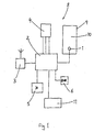
- FIG. 1 is a schematic block diagram of an anti-theft device 8 embodying the present invention.
- the device 8 comprises an accelerometer unit 4 having a plurality of outputs each connected to a respective input of a microprocessor unit 2.
- a battery 5 is provided to power the device 8.
- An output of the microprocessor unit 2 is connected to a detonator 1, which is adapted to ignite a pyrotechnic smoke generating composition 9.
- the smoke generating composition 9 contains a dyestuff 10, such that smoke generated thereby will stain anything that it touches, particularly currency paper and/or skin and clothing.
- the device 8 may optionally be provided with further selectably activatable elements, such as an audible alarm unit 6, a unit for dispersing a glue composition 11, and/or an RF signalling unit 3 to permit external tracking or location of the device 8.
- an audible alarm unit 6 a unit for dispersing a glue composition 11, and/or an RF signalling unit 3 to permit external tracking or location of the device 8.
- NB the RF unit 3 may also or alternatively be employed to receive RF signals as an additional activation or deactivation means).
- the accelerometer unit 4 is capable of detecting accelerations in any direction. Usually, it is set up to report accelerations along three mutually orthogonal axes. It is also capable of detecting an ambient gravitational field, and its orientation with respect thereto. From the data provided by the accelerometer unit 4, the microprocessor 2 calculates a range of data concerning motion of the device 8. For example, the microprocessor 2 can calculate velocities along said axes, and (e.g. by integration techniques) displacements along each axis from an initial position and an overall displacement therefrom. The microprocessor 2 also determines changes of orientation of the device 8. Additionally, the microprocessor 2 registers and sums the acceleration experienced by the device 8, a scalar sum of all accelerations undergone acting as a measure of agitation or vibration of the device 8.
- the device 8 has a quiescent mode, in which the power drain from the battery 5 is minimal. The battery life is estimated as three years if the device 8 remains in its quiescent mode.
- the device also has an active mode, in which the microprocessor 2 operates as described above, and in which the detonator 1 and the remaining activatable elements may be set off.
- the device 8 When the device 8 is first powered up by connection of the battery 5, it waits until its orientation has become constant for a predetermined period, and then enters its quiescent mode. Typically, this involves positioning a bundle of real or imitation notes concealing the device 8 in a cashier's till or the like. Depending on the till, the bundle may rest generally horizontally, or may be racked to extend in a generally vertical plane.
- activation of the device 8 from the quiescent mode is in response to a change of orientation of the device through 45° or more, optionally through at least 60°.
- opening or closing of the till would have no effect, but removal of the bundle from the till by anyone unaware of its mode of operation would activate the device 8. If, however, there is no motion in a set period following this activation, the device 8 returns to its quiescent mode.
- the microprocessor 2 keeps track of a total displacement of the device 8 since it was activated.
- the microprocessor 2 sets off the detonator 1, igniting the smoke composition 9. This generates clouds of coloured smoke, which indicate the presence of a robber, hinder his getaway (particularly if within a vehicle), stain his skin and clothing for easier identification, and stain any banknotes, etc, carried along with the bundle containing the device (thus making them impossible to use and easy to identify as stolen).
- liquid dye compositions or ink may be projected.
- glue unit 11 When a glue unit 11 is present, it will project glue on to the banknotes to prevent their use, and/or on to the robber so that the banknotes and/or device will stick to him, or he will stick to his surroundings. Where an RF unit 3 is present, this may be activated to emit a radio signal to facilitate tracking of the device 8.
- the microprocessor 2 at the same time sums the acceleration along all three orthogonal axes. Once the total acceleration experienced by the device 8 exceeds a pre-set level, the microprocessor 2 will activate the detonator 1, etc, as described above. Thus, rough handling of the bundle containing the device 8 will also cause activation.
- the microprocessor 2 also monitors these acceleration data for periods when little or no acceleration is occurring. After a predetermined period with no acceleration detected, the device 8 will be returned to its quiescent mode. (This may represent the bundle/device 8 having been dropped by the robber, for example). The summed acceleration may be reset to zero at this stage, to allow safe retrieval of the bundle/device 8 without risk of activation. If the robber picks up the bundle/device 8 again, the resulting change in orientation will start the microprocessor's calculations again, and rough handling, or taking the device beyond the preselected displacement threshold, will set the device 8 off as described above.
- the device 8 is thus independent of external signals or stimuli (except for gravity).
- the accelerometer cannot be shielded or jammed to prevent it registering unauthorised movement of the device 8.
Abstract
Description
- The present invention relates to a security device and to a security system which may employ said device. More particularly, but not exclusively, the present invention relates to a security device to protect cash, said device incorporating a means of generating smoke, especially coloured smoke.
- Many systems have been developed to address the problem of theft of cash. One approach is to provide devices, disguised as bundles of banknotes, which may be set off to emit copious clouds of coloured smoke, usually comprising a volatilised dye. This smoke may show that a robbery is in progress, hampers the escape of the robber or robbers, stains any banknotes being stolen so that they are then probably unusable, and stains the skin and clothing of the robber or robbers so that they may more easily be identified.
- It is known to provide triggering arrangements ranging from a simple time delay following removal of the device from a cash drawer, up to sophisticated systems such as that described in UK Patent No.
GB2372799 - It has been proposed to incorporate Radio Frequency (RF) receiver or transmission devices in some forms of security apparatus for cash protection, such as ATM machines, the cassettes for filling them, or in other cash carrying or storage containers. However, such wireless devices may be muffled or interrupted by specialist RF isolating equipment during a robbery, and afterwards hidden away and isolated in a Faraday cage or exposed to complex muffling waves for long periods of time, until the power supply on the RF receiver runs out, and thus the device eventually fails to set off its smoke generator. Furthermore, RF receivers may have high power consumption and therefore their power supply would need to be replaced or recharged at regular intervals. If their power supply is impaired or cut off, such devices soon become ineffective or may operate only for a short period.
- It would thus be advantageous if the device could be independent of external stimuli such as an RF or GPS transducer signal, but still able to determine how far it has been displaced relative to an initial rest position, automatically activating a detonator to ignite a smoke composition containing dye or coloured ink, also hidden within the cash, once said displacement exceeds a threshold value.
- It would also be advantageous for the device to have as low a power consumption as possible when not activated, to reduce the chance of the device becoming accidentally or deliberately inactivated through exhaustion of its power supply.
- It is hence an object of the present invention to provide a security device adapted for concealment in or with bundles of banknotes or the like, which provides some or all of the above advantages and obviates some or all of the above disadvantages.
- According to a first aspect of the present invention, there is provided an anti-theft device comprising means to emit a medium adapted to discourage theft, accelerometer means and means to calculate motion data based on output from the accelerometer means, said emission means being adapted to be activated in response to a predetermined motion datum exceeding a preselected threshold value.
- Preferably, said predetermined motion datum comprises a net displacement of the device.
- Advantageously, said predetermined motion datum comprises a summed acceleration undergone by the device.
- Preferably, the anti-theft device has an active mode in which said motion calculating means calculates said motion data, and a quiescent mode in which the emission means is not activatable.
- Advantageously, the accelerometer means is adapted to detect a change in orientation of the device, and the device enters an armed mode in response to a change in orientation exceeding a predetermined threshold value, optionally a change in orientation exceeding about 45°, alternatively exceeding about 60°.
- The device may be adapted to re-enter its quiescent mode if less than a predetermined threshold movement is detected in a predetermined period of time following said change in orientation, optionally if no movement is detected in said period.
- The device may be adapted to enter its quiescent mode following any period having a preselected duration during which no acceleration is detected.
- Preferably, the accelerometer means is adapted to register acceleration along three mutually orthogonal axes.
- Advantageously, the accelerometer means is adapted to determine its orientation relative to an ambient gravitational field.
- Preferably, the emission means is adapted to emit smoke means, optionally obscuring smoke means.
- Advantageously, the emission means comprises a pyrotechnic composition, optionally ignitable by detonator means activatable by the calculating means.
- The emission means may be adapted to emit dye means, optionally comprising ink means.
- Additionally or alternatively, the emission means may comprise means to dispense an adhesive composition.
- Preferably, the anti-theft device is adapted to be concealed within a package of genuine or imitation bank notes.
- The anti-theft device may be provided with locator means adapted to be activated substantially simultaneously with the emission means.
- The device may comprise means to detect motion and means operable in response thereto to determine acceleration of the device, means to compute traversed distance and means to activate detonator means after a predetermined distance of the device has been traversed.
- Preferably, the motion detector means comprises accelerometer means.
- Advantageously, this enables the device to sense movement.
- Alternatively or additionally, the motion detector means may comprise tilt switch means.
- Preferably, the motion detector means is adapted to detect motion in three dimensions.
- This enables accurate computation of a specific direction of motion based on data received from the motion detector means.
- Preferably, the accelerometer means is adapted to determine orientation in three-dimensional frame of reference.
- The device may thus accurately measure angles of tilt in a plurality of alignments.
- Preferably, the device is concealable within a bundle of genuine or imitation bank notes.
- This provides camouflage and lessens the risk of thieves removing it from the cash bundle.
- Preferably, the device is adapted to detect unauthorised disconnection of the motion detector means and in response to activate the emission means.
- Preferably, the device comprises microprocessor control means enabling rapid exchange of data among integers of the device.
- The control means may be adapted to classify and to count successive time intervals of predetermined length as motion intervals or non-motion intervals, according to whether an amount of motion in a respective time interval exceeds a predetermined threshold.
- The control means may then activate the emission means only following a first predetermined number of said motion intervals.
- Preferably, the accelerometer means is sensitive to both low and high forces.
- The accelerometer means may be adapted to sense ambient gravitational forces.
- The accelerometer means may be adapted to detect its orientation with respect to gravity and/or to detect changes in its orientation.
- Preferably, the device is adapted to enter an active mode in response to a change in orientation of 45° or greater, optionally 60° or greater.
- According to a second aspect of the invention, there is provided a method for controlling an anti-theft device comprising the steps of providing an anti-theft device as described in the first aspect above, computing a distance traversed by the device, and activating initiator means after a predetermined distance has been traversed, so as to emit from the device a medium adapted to discourage theft.
- Said medium may comprise smoke means, dye means and/or adhesive means.
- Preferably, the method comprises the steps of monitoring motion in three dimensions and calculating therefrom the distance traversed.
- The method may comprise the step of activating the device in response to a change in its orientation of 45° or greater, optionally of 60° or greater.
- According to a third aspect of the present invention, there is provided a system for computing the distance traversed by a device, comprising means to detect motion and means operable in response thereto to compute traversed distance, and initiator means activatable after a predetermined distance is traversed to emit a medium adapted to discourage theft, such as smoke, dye means and/or adhesive means.
- Preferably, the device is activated whenever there is an orientation change of equal to or greater than 45 degrees, optionally 60° or greater.
- Advantageously, the device comprises means to compute acceleration or deceleration over time when the device is activated, and thereby to calculate the distance travelled.
- The device may comprise means to calculate a sum of accelerations in three orthogonal planes and to ascertain whether a predetermined acceleration threshold level is surpassed.
- The device may be adapted to return the device to a quiescent mode after a predetermined quiet period without acceleration.
- Preferably, the system is adapted to detect acceleration along at least two orthogonal axes, advantageously along three mutually orthogonal axes.
- The control means may be adapted to distinguish between different types of signals from the motion detector means, optionally between those corresponding to translational movement and those signals corresponding to vibrational movement
- The control means may then be adapted to respond only to signals corresponding to translational movement.
- Alternatively or additionally, the control means may also be adapted to respond to signals corresponding to vibrational movement.
- This allows the control means simultaneously to compute an average velocity and to ascertain whether a vibrational threshold has been surpassed.
- This allows computation of the distance traversed, and if the vibration threshold level or a distance threshold has been surpassed, generation of an activation signal to the control means to instigate detonation of the device.
- Advantageously, the device comprises means to transmit an 'activate' signal to detonator means thereof more rapidly than detonation would propagate spontaneously therethrough.
- Additionally, the device may comprise reed switch means, adapted to detect removal of the tracking device from an authorised position.
- The device may additionally be activatable by leaving a radio-frequency field or by GPS tracking, for example such a field set up within a bank, shop, security vehicle, automatic teller machine (ATM) casing or the like.
- The device may optionally be activatable on command, for example by means of a radio command signal transmitted thereto.
- The device may be activatable on tampering with the device or on tampering with a container in which it is located.
- Said activation of the device may optionally take effect only after a predetermined delay period.
- An embodiment of the present invention will now be more particularly described by way of example and with reference to the Figure of the accompanying drawings, in which:
-
Figure 1 is a schematic block diagram of an anti-theft device embodying the present invention. - An anti-theft device comprises a charge of a smoke generating pyrotechnic composition, containing a dyestuff, operatively linked to a control circuit provided with means to detect acceleration such as an accelerometer unit and means to determine motion parameters, such as velocity and displacement from rest. The device is adapted to emit an anti-theft deterrent dye, coloured smoke, or the like, on receipt of a signal from the control circuit that the device has travelled a predetermined distance from an initial settled position. A tracking device may also then be activated.
- The composition may emit a liquid dye, an ink or a coloured smoke. The control circuit in a simple embodiment may comprise motion sensors such as an accelerometer to detect translational acceleration and vibrational acceleration, a microprocessor system to process data, and an ignition circuit connected to a squib or detector embedded in a charge of the composition. The device may be camouflaged to appear as a bundle of banknotes and be kept in a cash drawer in, for example, a bank. Optionally, an RF field may be set up within the bank premises to complement the accelerometer system, to be picked up by an RF detector of the device.
- In one version, the device may be given to or taken by a robber, mixed in with genuine bundles of banknotes. Alternatively, it may be incorporated in a cash cassette or cash carrying device. The device is activated from its initially quiescent state by being turned through an angle of at least 45°. Once the robber starts moving, the accelerometer detects motion in one or more orthogonal axes. The control circuit concurrently initiates a delay timer, counting to a predetermined time to see if the motion continues. If the motion stops the device relearns its orientation and returns to the quiescent mode. If the device remains active, it sums a scalar total of acceleration and deceleration over time, and also calculates a distance moved. Once the device is a predetermined distance away from its original position, or once the scalar total acceleration exceeds a predetermined limit, it will fire a squib, igniting the charge, which emits copious amounts of coloured smoke, or alternatively emits a liquid dye or ink to stain the banknotes for subsequent identification. The device may also or alternatively project glue over the banknotes or over a person holding them. A tracking system may also be activated to aid location of the device, e.g. by the police.
- In other embodiments, more complex control arrangements may be employed, such as those disclosed in our
UK Patent No. 2372799 - Additionally, to assist location of the banknotes and possibly the robber, a tracking device may be provided comprising a GPS location system, a radio transmitter (for example, one capable of using existing mobile telephone networks to call a central control room to interact with a GSM system). The tracking device may be incorporated into the anti-theft device itself, may be incorporated in the same imitation bundle of banknotes as the anti-theft device, or it may disguised as a further bundle of banknotes.
- The system relies on an accelerometer, a measuring device for acceleration, detecting and measuring vibrations, or for measuring acceleration due to gravity (inclination). An accelerometer measures its own motion, in contrast to a device based on remote sensing.
- Historically, accelerometers have been used in many scientific and industrial application such as predictive maintenance, aerospace, automotive, medical, process control, etc. In many cases they consist of a suspended cautilever beam or proof mass (also known as seismic mass) with associated deflection sensing and circuitry, and comprise one of the simplest forms of microelectromechanical systems (MEMs).
- It is known to provide accelerometers using other principles of operation for the measurement of acceleration, shock or vibration. Some of the common types use one or more of capacitive; piezoelectric; piezoresistive; Hall effect; magnetoresistive and/or heat transfer principles in their implementation.
-
Figure 1 is a schematic block diagram of ananti-theft device 8 embodying the present invention. Thedevice 8 comprises an accelerometer unit 4 having a plurality of outputs each connected to a respective input of a microprocessor unit 2. Abattery 5 is provided to power thedevice 8. An output of the microprocessor unit 2 is connected to adetonator 1, which is adapted to ignite a pyrotechnicsmoke generating composition 9. Thesmoke generating composition 9 contains adyestuff 10, such that smoke generated thereby will stain anything that it touches, particularly currency paper and/or skin and clothing. Thedevice 8 may optionally be provided with further selectably activatable elements, such as anaudible alarm unit 6, a unit for dispersing aglue composition 11, and/or anRF signalling unit 3 to permit external tracking or location of thedevice 8. (NB: theRF unit 3 may also or alternatively be employed to receive RF signals as an additional activation or deactivation means). - The accelerometer unit 4 is capable of detecting accelerations in any direction. Usually, it is set up to report accelerations along three mutually orthogonal axes. It is also capable of detecting an ambient gravitational field, and its orientation with respect thereto. From the data provided by the accelerometer unit 4, the microprocessor 2 calculates a range of data concerning motion of the
device 8. For example, the microprocessor 2 can calculate velocities along said axes, and (e.g. by integration techniques) displacements along each axis from an initial position and an overall displacement therefrom. The microprocessor 2 also determines changes of orientation of thedevice 8. Additionally, the microprocessor 2 registers and sums the acceleration experienced by thedevice 8, a scalar sum of all accelerations undergone acting as a measure of agitation or vibration of thedevice 8. - This permits operation of the device as follows. The
device 8 has a quiescent mode, in which the power drain from thebattery 5 is minimal. The battery life is estimated as three years if thedevice 8 remains in its quiescent mode. The device also has an active mode, in which the microprocessor 2 operates as described above, and in which thedetonator 1 and the remaining activatable elements may be set off. - When the
device 8 is first powered up by connection of thebattery 5, it waits until its orientation has become constant for a predetermined period, and then enters its quiescent mode. Typically, this involves positioning a bundle of real or imitation notes concealing thedevice 8 in a cashier's till or the like. Depending on the till, the bundle may rest generally horizontally, or may be racked to extend in a generally vertical plane. - In either case, activation of the
device 8 from the quiescent mode is in response to a change of orientation of the device through 45° or more, optionally through at least 60°. Thus, opening or closing of the till would have no effect, but removal of the bundle from the till by anyone unaware of its mode of operation would activate thedevice 8. If, however, there is no motion in a set period following this activation, thedevice 8 returns to its quiescent mode. - Once the device is active, the microprocessor 2 keeps track of a total displacement of the
device 8 since it was activated. When the total displacement reaches a preselected threshold value (say 50 metres, to ensure that thedevice 8 would have by then been removed from a bank premises or the like by a robber, etc), the microprocessor 2 sets off thedetonator 1, igniting thesmoke composition 9. This generates clouds of coloured smoke, which indicate the presence of a robber, hinder his getaway (particularly if within a vehicle), stain his skin and clothing for easier identification, and stain any banknotes, etc, carried along with the bundle containing the device (thus making them impossible to use and easy to identify as stolen). In other variants, liquid dye compositions or ink may be projected. Where aglue unit 11 is present, it will project glue on to the banknotes to prevent their use, and/or on to the robber so that the banknotes and/or device will stick to him, or he will stick to his surroundings. Where anRF unit 3 is present, this may be activated to emit a radio signal to facilitate tracking of thedevice 8. - The microprocessor 2 at the same time sums the acceleration along all three orthogonal axes. Once the total acceleration experienced by the
device 8 exceeds a pre-set level, the microprocessor 2 will activate thedetonator 1, etc, as described above. Thus, rough handling of the bundle containing thedevice 8 will also cause activation. - The microprocessor 2 also monitors these acceleration data for periods when little or no acceleration is occurring. After a predetermined period with no acceleration detected, the
device 8 will be returned to its quiescent mode. (This may represent the bundle/device 8 having been dropped by the robber, for example). The summed acceleration may be reset to zero at this stage, to allow safe retrieval of the bundle/device 8 without risk of activation. If the robber picks up the bundle/device 8 again, the resulting change in orientation will start the microprocessor's calculations again, and rough handling, or taking the device beyond the preselected displacement threshold, will set thedevice 8 off as described above. - The
device 8 is thus independent of external signals or stimuli (except for gravity). The accelerometer cannot be shielded or jammed to prevent it registering unauthorised movement of thedevice 8. Furthermore, unlike existing systems based on the reception of RF signals to indicate to a device its location, it is not necessary to set up a network of transmitters to protect a bank premises or the like. Both set-up and running costs are thus substantially lower than for existing systems.
Claims (15)
- An anti-theft device (8) comprising means (9, 11) to emit a medium (10) adapted to discourage theft, characterised in that the device (8) comprises accelerometer means (4) and means (2) to calculate motion data based on output from the accelerometer means (4), and said emission means (9, 11) is adapted to be activated in response to a predetermined motion datum exceeding a preselected threshold value.
- An anti-theft device as claimed in claim 1, characterised in that said predetermined motion datum comprises a net displacement of the device (8).
- An anti-theft device as claimed in either claim 1 or claim 2, characterised in that said predetermine motion datum comprises a summed acceleration undergone by the device (8).
- An anti-theft device as claimed in any one of the preceding claims, characterised in that said device (8) has an active mode in which said motion calculating means calculates said motion data, and a quiescent mode in which the emission means (9, 11) is not activatable.
- An anti-theft device as claimed in claim 4, characterised in that the accelerometer means (4) is adapted to detect a change in orientation of the device (8), and the device (8) enters its armed mode in response to a change in orientation exceeding a predetermined threshold value, optionally a change in orientation exceeding about 45°, alternatively exceeding about 60°.
- An anti-theft device as claimed in claim 5, characterised in that the device (8) is adapted to re-enter its quiescent mode if less than a predetermined threshold movement is detected in a predetermined period of time following said change in orientation, optionally if no movement is detected in said period.
- An anti-theft device as claimed in any one of claims 4 to 6, characterised in that the device is adapted to enter its quiescent mod following any period having a preselected duration during which no acceleration is detected.
- An anti-theft device as claimed in any one of the preceding claims, characterised in that the accelerometer means (4) is adapted to register acceleration along three mutually orthogonal axes.
- An anti-theft device as claimed in any one of the preceding claims, characterised in that the accelerometer means (4) is adapted to determine its orientation relative to an ambient gravitational field.
- An anti-theft device as claimed in any of the preceding claims, characterised in that the emission means (9) is adapted to emit smoke means, optionally obscuring smoke means.
- An anti-theft device as claimed in claim 10, characterised in that the emission means (9) comprises a pyrotechnic composition, optionally ignitable by detonator means (1) activatable by the calculating means (2).
- An anti-theft device as claimed in any one of the preceding claims, characterised in that the emission means (9) is adapted to emit dye means (10), optionally comprising ink means.
- An anti-theft device as claimed in any one of the preceding claims, characterised in that the emission means (11) comprises means to dispense an adhesive composition.
- An anti-theft device as claimed in any one of the preceding claims, adapted to be concealed within a package of genuine or imitation bank notes.
- An anti-theft device as claimed in any one of the preceding claims, comprising locator means (3) adapted to be activated substantially simultaneously with the emission means (9, 11).
Applications Claiming Priority (1)
| Application Number | Priority Date | Filing Date | Title |
|---|---|---|---|
| GB0717858A GB0717858D0 (en) | 2007-09-13 | 2007-09-13 | Security system |
Publications (2)
| Publication Number | Publication Date |
|---|---|
| EP2037424A2 true EP2037424A2 (en) | 2009-03-18 |
| EP2037424A3 EP2037424A3 (en) | 2010-05-05 |
Family
ID=38658892
Family Applications (1)
| Application Number | Title | Priority Date | Filing Date |
|---|---|---|---|
| EP08016201A Withdrawn EP2037424A3 (en) | 2007-09-13 | 2008-09-15 | Security system |
Country Status (2)
| Country | Link |
|---|---|
| EP (1) | EP2037424A3 (en) |
| GB (2) | GB0717858D0 (en) |
Cited By (3)
| Publication number | Priority date | Publication date | Assignee | Title |
|---|---|---|---|---|
| EP2905758A1 (en) | 2014-02-06 | 2015-08-12 | Wincor Nixdorf International GmbH | Device for monitoring a container |
| WO2016131756A1 (en) * | 2015-02-17 | 2016-08-25 | Robert Bosch Gmbh | Theft protection device for an article |
| WO2018084781A1 (en) * | 2016-11-03 | 2018-05-11 | Strongpoint Cash Security Ab | Container for carrying valuables and method of manipulating valuables in response of rapid movement of such container |
Families Citing this family (2)
| Publication number | Priority date | Publication date | Assignee | Title |
|---|---|---|---|---|
| GB0918314D0 (en) * | 2009-10-19 | 2009-12-02 | Sharp Graham D F | A process for making stolen money notes unusable |
| DE102010041126A1 (en) * | 2010-09-21 | 2012-03-01 | Siemens Aktiengesellschaft | Photovoltaic device used in e.g. solar park, has anti-theft device comprising radio element that emits radio signal based on acceleration characteristic received from acceleration signal output by acceleration sensor |
Citations (2)
| Publication number | Priority date | Publication date | Assignee | Title |
|---|---|---|---|---|
| GB2372799A (en) | 2000-12-01 | 2002-09-04 | Ibp Internat Ltd | Security system including a smoke composition |
| US20040066302A1 (en) * | 2001-03-28 | 2004-04-08 | Menard Raymond J. | Interactive motion sensitive sensor |
Family Cites Families (11)
| Publication number | Priority date | Publication date | Assignee | Title |
|---|---|---|---|---|
| US4945347A (en) * | 1988-03-17 | 1990-07-31 | Perry John C | Motion and orientation responsive device for seismic, intrusion, and tilt alarms and the like |
| GB8813874D0 (en) * | 1988-06-11 | 1988-07-13 | Transalarm Ltd | Security system |
| US5148150A (en) * | 1991-01-07 | 1992-09-15 | Cra West Incorporation | Compact security alarm circuitry and apparatus for portable containers |
| GB2280056A (en) * | 1993-07-17 | 1995-01-18 | Transalarm Ltd | A security container |
| GB2306736A (en) * | 1995-11-03 | 1997-05-07 | Motorola Inc | Method and apparatus to provide security for a movable article |
| FR2822880B1 (en) * | 2001-03-29 | 2003-12-26 | Brinks France | SECURITY DEVICE FOR STORING AND TRANSPORTING VALUES OR DOCUMENTS |
| FR2827618B1 (en) * | 2001-07-18 | 2003-10-03 | Banque De France | DOCUMENT SECURING PROCESS |
| JP2005158000A (en) * | 2003-11-25 | 2005-06-16 | Yoshio Kitagawa | Device where bank bill is made unusable in state where bank bill stored inside duralumin case can be exchanged later in bank of japan when duralumin case for conveying bank bill is stolen |
| US7183915B2 (en) * | 2004-08-05 | 2007-02-27 | 3Si Security Systems, Inc. | Wireless ATM security system |
| US20060204232A1 (en) * | 2005-02-01 | 2006-09-14 | Harvey Weinberg | Camera with acceleration sensor |
| GB0502202D0 (en) * | 2005-02-03 | 2005-03-09 | Ibp Internat Ltd | Tracking device |
-
2007
- 2007-09-13 GB GB0717858A patent/GB0717858D0/en not_active Ceased
-
2008
- 2008-09-15 GB GB0816853.6A patent/GB2452855B/en not_active Expired - Fee Related
- 2008-09-15 EP EP08016201A patent/EP2037424A3/en not_active Withdrawn
Patent Citations (2)
| Publication number | Priority date | Publication date | Assignee | Title |
|---|---|---|---|---|
| GB2372799A (en) | 2000-12-01 | 2002-09-04 | Ibp Internat Ltd | Security system including a smoke composition |
| US20040066302A1 (en) * | 2001-03-28 | 2004-04-08 | Menard Raymond J. | Interactive motion sensitive sensor |
Cited By (5)
| Publication number | Priority date | Publication date | Assignee | Title |
|---|---|---|---|---|
| EP2905758A1 (en) | 2014-02-06 | 2015-08-12 | Wincor Nixdorf International GmbH | Device for monitoring a container |
| WO2016131756A1 (en) * | 2015-02-17 | 2016-08-25 | Robert Bosch Gmbh | Theft protection device for an article |
| WO2018084781A1 (en) * | 2016-11-03 | 2018-05-11 | Strongpoint Cash Security Ab | Container for carrying valuables and method of manipulating valuables in response of rapid movement of such container |
| EP3535736A4 (en) * | 2016-11-03 | 2020-07-01 | Strongpoint Cash Security AB | Container for carrying valuables and method of manipulating valuables in response of rapid movement of such container |
| RU2758204C2 (en) * | 2016-11-03 | 2021-10-26 | Стронгпойнт Кэш Секьюрити Аб | Container for carrying valuable things and method for processing valuable things in response to fast movement of such a container |
Also Published As
| Publication number | Publication date |
|---|---|
| GB2452855B (en) | 2012-12-26 |
| EP2037424A3 (en) | 2010-05-05 |
| GB0717858D0 (en) | 2007-10-24 |
| GB2452855A (en) | 2009-03-18 |
| GB0816853D0 (en) | 2008-10-22 |
Similar Documents
| Publication | Publication Date | Title |
|---|---|---|
| CA2462524C (en) | Tracking system for locating stolen currency | |
| US5952920A (en) | Currency anti-theft device | |
| EP2037424A2 (en) | Security system | |
| EP2510506B1 (en) | A security apparatus | |
| US20120247373A1 (en) | Protection and Tracking System for Valuables | |
| EP2209097A1 (en) | Vending enclosure recovery method and system | |
| CN105917394A (en) | Method and device for determining unauthorized intrusion at door | |
| ES2368351T3 (en) | METHOD AND DEVICE FOR SECURING A SPACE AGAINST GAS EXPLOSION HAZARD. | |
| EP1566513A2 (en) | Security container | |
| EP0736850A1 (en) | Method for preventing shoplifting and electronic theft detection system | |
| EP1688897B1 (en) | Tracking device | |
| WO2014047272A1 (en) | Merchandise security device including motion sensor for activating audio indicator | |
| EP0848130A2 (en) | Improved safe | |
| JP3884946B2 (en) | Security device | |
| GB2372799A (en) | Security system including a smoke composition | |
| WO2019193465A1 (en) | Kit for safe deposit box and method of use | |
| EP3535736B1 (en) | Container for carrying valuables and method of manipulating valuables in response of rapid movement of such container | |
| EP0629984A1 (en) | Anti-theft system for jewellery | |
| JP2006039775A (en) | Crime prevention device | |
| DE102007055523A1 (en) | Device for preventing pick-pocketing and robbery, comprises detection system, which is attached to article to be protected, which notices any movement sequence in sensor in normal usage | |
| BG111151A (en) | Method and portable alarm device for warning and protection of portable and mobile objects by data processing by accelerometer | |
| CZ19388U1 (en) | Safety system | |
| ITPR20090015A1 (en) | ANTI-INTRUSION SYSTEM | |
| WO2012095663A1 (en) | Protection of articles against theft |
Legal Events
| Date | Code | Title | Description |
|---|---|---|---|
| PUAI | Public reference made under article 153(3) epc to a published international application that has entered the european phase |
Free format text: ORIGINAL CODE: 0009012 |
|
| AK | Designated contracting states |
Kind code of ref document: A2 Designated state(s): AT BE BG CH CY CZ DE DK EE ES FI FR GB GR HR HU IE IS IT LI LT LU LV MC MT NL NO PL PT RO SE SI SK TR |
|
| AX | Request for extension of the european patent |
Extension state: AL BA MK RS |
|
| PUAL | Search report despatched |
Free format text: ORIGINAL CODE: 0009013 |
|
| AK | Designated contracting states |
Kind code of ref document: A3 Designated state(s): AT BE BG CH CY CZ DE DK EE ES FI FR GB GR HR HU IE IS IT LI LT LU LV MC MT NL NO PL PT RO SE SI SK TR |
|
| AX | Request for extension of the european patent |
Extension state: AL BA MK RS |
|
| AKY | No designation fees paid | ||
| REG | Reference to a national code |
Ref country code: DE Ref legal event code: 8566 |
|
| 17P | Request for examination filed |
Effective date: 20110223 |
|
| RBV | Designated contracting states (corrected) |
Designated state(s): AT BE BG CH CY CZ DE DK EE ES FI FR GB GR HR HU IE IS IT LI LT LU LV MC MT NL NO PL PT RO SE SI SK TR |
|
| 17Q | First examination report despatched |
Effective date: 20110408 |
|
| 18D | Application deemed to be withdrawn |
Effective date: 20111019 |
|
| 18RA | Request filed for re-establishment of rights before grant |
Effective date: 20121219 |
|
| D18D | Application deemed to be withdrawn (deleted) | ||
| STAA | Information on the status of an ep patent application or granted ep patent |
Free format text: STATUS: THE APPLICATION IS DEEMED TO BE WITHDRAWN |
|
| R18D | Application deemed to be withdrawn (corrected) |
Effective date: 20180404 |