EP2037285A1 - Combined sensor - Google Patents
Combined sensor Download PDFInfo
- Publication number
- EP2037285A1 EP2037285A1 EP07805914A EP07805914A EP2037285A1 EP 2037285 A1 EP2037285 A1 EP 2037285A1 EP 07805914 A EP07805914 A EP 07805914A EP 07805914 A EP07805914 A EP 07805914A EP 2037285 A1 EP2037285 A1 EP 2037285A1
- Authority
- EP
- European Patent Office
- Prior art keywords
- detection element
- arms
- angular velocity
- acceleration
- weight parts
- Prior art date
- Legal status (The legal status is an assumption and is not a legal conclusion. Google has not performed a legal analysis and makes no representation as to the accuracy of the status listed.)
- Withdrawn
Links
Images




Classifications
-
- G—PHYSICS
- G01—MEASURING; TESTING
- G01C—MEASURING DISTANCES, LEVELS OR BEARINGS; SURVEYING; NAVIGATION; GYROSCOPIC INSTRUMENTS; PHOTOGRAMMETRY OR VIDEOGRAMMETRY
- G01C19/00—Gyroscopes; Turn-sensitive devices using vibrating masses; Turn-sensitive devices without moving masses; Measuring angular rate using gyroscopic effects
- G01C19/56—Turn-sensitive devices using vibrating masses, e.g. vibratory angular rate sensors based on Coriolis forces
- G01C19/5719—Turn-sensitive devices using vibrating masses, e.g. vibratory angular rate sensors based on Coriolis forces using planar vibrating masses driven in a translation vibration along an axis
-
- G—PHYSICS
- G01—MEASURING; TESTING
- G01P—MEASURING LINEAR OR ANGULAR SPEED, ACCELERATION, DECELERATION, OR SHOCK; INDICATING PRESENCE, ABSENCE, OR DIRECTION, OF MOVEMENT
- G01P15/00—Measuring acceleration; Measuring deceleration; Measuring shock, i.e. sudden change of acceleration
- G01P15/02—Measuring acceleration; Measuring deceleration; Measuring shock, i.e. sudden change of acceleration by making use of inertia forces using solid seismic masses
- G01P15/08—Measuring acceleration; Measuring deceleration; Measuring shock, i.e. sudden change of acceleration by making use of inertia forces using solid seismic masses with conversion into electric or magnetic values
- G01P15/09—Measuring acceleration; Measuring deceleration; Measuring shock, i.e. sudden change of acceleration by making use of inertia forces using solid seismic masses with conversion into electric or magnetic values by piezoelectric pick-up
- G01P15/0922—Measuring acceleration; Measuring deceleration; Measuring shock, i.e. sudden change of acceleration by making use of inertia forces using solid seismic masses with conversion into electric or magnetic values by piezoelectric pick-up of the bending or flexing mode type
-
- G—PHYSICS
- G01—MEASURING; TESTING
- G01P—MEASURING LINEAR OR ANGULAR SPEED, ACCELERATION, DECELERATION, OR SHOCK; INDICATING PRESENCE, ABSENCE, OR DIRECTION, OF MOVEMENT
- G01P15/00—Measuring acceleration; Measuring deceleration; Measuring shock, i.e. sudden change of acceleration
- G01P15/02—Measuring acceleration; Measuring deceleration; Measuring shock, i.e. sudden change of acceleration by making use of inertia forces using solid seismic masses
- G01P15/08—Measuring acceleration; Measuring deceleration; Measuring shock, i.e. sudden change of acceleration by making use of inertia forces using solid seismic masses with conversion into electric or magnetic values
- G01P15/12—Measuring acceleration; Measuring deceleration; Measuring shock, i.e. sudden change of acceleration by making use of inertia forces using solid seismic masses with conversion into electric or magnetic values by alteration of electrical resistance
- G01P15/123—Measuring acceleration; Measuring deceleration; Measuring shock, i.e. sudden change of acceleration by making use of inertia forces using solid seismic masses with conversion into electric or magnetic values by alteration of electrical resistance by piezo-resistive elements, e.g. semiconductor strain gauges
-
- G—PHYSICS
- G01—MEASURING; TESTING
- G01P—MEASURING LINEAR OR ANGULAR SPEED, ACCELERATION, DECELERATION, OR SHOCK; INDICATING PRESENCE, ABSENCE, OR DIRECTION, OF MOVEMENT
- G01P15/00—Measuring acceleration; Measuring deceleration; Measuring shock, i.e. sudden change of acceleration
- G01P15/18—Measuring acceleration; Measuring deceleration; Measuring shock, i.e. sudden change of acceleration in two or more dimensions
-
- G—PHYSICS
- G01—MEASURING; TESTING
- G01P—MEASURING LINEAR OR ANGULAR SPEED, ACCELERATION, DECELERATION, OR SHOCK; INDICATING PRESENCE, ABSENCE, OR DIRECTION, OF MOVEMENT
- G01P15/00—Measuring acceleration; Measuring deceleration; Measuring shock, i.e. sudden change of acceleration
- G01P15/02—Measuring acceleration; Measuring deceleration; Measuring shock, i.e. sudden change of acceleration by making use of inertia forces using solid seismic masses
- G01P15/08—Measuring acceleration; Measuring deceleration; Measuring shock, i.e. sudden change of acceleration by making use of inertia forces using solid seismic masses with conversion into electric or magnetic values
- G01P2015/0805—Measuring acceleration; Measuring deceleration; Measuring shock, i.e. sudden change of acceleration by making use of inertia forces using solid seismic masses with conversion into electric or magnetic values being provided with a particular type of spring-mass-system for defining the displacement of a seismic mass due to an external acceleration
- G01P2015/0822—Measuring acceleration; Measuring deceleration; Measuring shock, i.e. sudden change of acceleration by making use of inertia forces using solid seismic masses with conversion into electric or magnetic values being provided with a particular type of spring-mass-system for defining the displacement of a seismic mass due to an external acceleration for defining out-of-plane movement of the mass
- G01P2015/084—Measuring acceleration; Measuring deceleration; Measuring shock, i.e. sudden change of acceleration by making use of inertia forces using solid seismic masses with conversion into electric or magnetic values being provided with a particular type of spring-mass-system for defining the displacement of a seismic mass due to an external acceleration for defining out-of-plane movement of the mass the mass being suspended at more than one of its sides, e.g. membrane-type suspension, so as to permit multi-axis movement of the mass
- G01P2015/0842—Measuring acceleration; Measuring deceleration; Measuring shock, i.e. sudden change of acceleration by making use of inertia forces using solid seismic masses with conversion into electric or magnetic values being provided with a particular type of spring-mass-system for defining the displacement of a seismic mass due to an external acceleration for defining out-of-plane movement of the mass the mass being suspended at more than one of its sides, e.g. membrane-type suspension, so as to permit multi-axis movement of the mass the mass being of clover leaf shape
Definitions
- the present invention relates to a combined sensor for detecting angular velocity and acceleration, which is used in various electronic devices for attitude control or navigation of mobile objects such as aircrafts, automobiles, robots, marine vehicles, and other vehicles.
- Conventional combined sensors for detecting angular velocity and acceleration are generally formed of angular velocity sensors for detecting angular velocity and acceleration sensors for detecting acceleration.
- an electronic device in order to detect angular velocity and acceleration at the same time, an electronic device is required to have a plurality of angular velocity sensors and a plurality of acceleration sensors mounted on the substrate.
- an angular velocity sensor detects angular velocity by vibrating a detection element that can be formed in different shapes such as tuning-fork-shaped, H-shaped, or T-shaped, and by electrically detecting distortion of the angular velocity detection element caused by the Coriolis force.
- An acceleration sensor has weight parts and detects acceleration by making an acceleration detection element compare the acceleration before and after the movement of the weight parts.
- a combined sensor includes, for example, an angular velocity sensor and an acceleration sensor so as to detect angular velocity and acceleration at the same time.
- angular velocity sensors are positioned along the respective axes of an attitude control system or a navigation system used in motor vehicles or other mobile objects.
- Patent Documents 1 and 2 Such a conventional technique related to the present invention is shown, for example, in Patent Documents 1 and 2 below.
- the angular velocity sensors and the acceleration sensors are individually mounted on the substrate in such a manner as to be positioned along the respective axes for detecting angular velocity or acceleration. This requires a large mounting area, thus preventing the miniaturization of the combined sensor.
- an object of the present invention is to provide a combined sensor for detecting angular velocity and acceleration, which requires a smaller mounting area, thereby being miniaturized.
- the combined detection element of the present invention includes an acceleration detection element and an angular velocity detection element stacked on the acceleration detection element in such a manner as to avoid contacting with the weight parts of the acceleration detection element.
- the angular velocity detection element includes suppressing portions for suppressing the upward movement of the weight parts of the acceleration detection element.
- the combined detection element which is thus structured by stacking the angular velocity detection element and the acceleration detection element on top of each other, requires a smaller mounting area, thereby being miniaturized.
- the angular velocity detection element is stacked on the acceleration detection element in such a manner as to avoid contacting with the weight parts of the acceleration detection element.
- the angular velocity detection element includes the suppressing portions for suppressing the upward movement of the weight parts of the acceleration detection element. Therefore, even when acceleration exceeding the allowable vertical movement of the weight parts is applied, the suppressing portions for suppressing the vertical movement of the weight parts limit the vertical range of motion within a specified range, thereby preventing the breakage of the acceleration detection element. The suppression of the vertical movement also prevents the breakage of the angular velocity detection element.
- the acceleration detection element detects an acceleration signal, which is then electrically processed, so that the acceleration detection element functions as an acceleration sensor.
- the angular velocity detection element detects an angular velocity signal, which is then electrically processed, so that the angular velocity detection element functions as an acceleration signal.
- the angular velocity detection element and the acceleration detection element stacked on top of each other detect these signals which are then electrically processed.
- the detection elements function as an acceleration sensor and an angular velocity sensor, respectively, thereby functioning as a combined sensor including an acceleration sensor and an angular velocity sensor.
- Fig. 1 is an exploded perspective view of a combined detection element which forms a combined sensor according to an embodiment of the present invention.
- Fig. 2 is a perspective view of the combined detection element.
- Fig. 3 is a sectional view of the combined detection element taken along line 2A-2A of Fig. 2 .
- the combined sensor of the present invention includes a combined detection element and a signal processor (not shown) for electrically processing a detection signal received from the combined detection element.
- the combined sensor according to the embodiment shown in Figs. 1 to 3 includes combined detection element 6 having acceleration detection element 2 and angular velocity detection element 4.
- Acceleration detection element 2 includes frame-like fixing arm 8 fixed to a mounting substrate, four connecting arms 10 connected together at one end and connected to fixing arm 8 at the other end, and weight parts 12 used for detecting acceleration. Weight parts 12 are arranged between four connecting arms 10 and connected to one end of each of four connecting arms 10. Four connecting arms 10 can be bent due to the movement of weight parts 12.
- Angular velocity detection element 4 includes two first orthogonal arms, two second orthogonal arms, and support portion 19.
- the first orthogonal arms are each T-shaped in which one first arm 16 is sandwiched in a substantially orthogonal direction between two second arms 18 and connected thereto.
- the two second orthogonal arms each consist of one first arm 16 and one third arm 20 connected in a substantially orthogonal direction thereto.
- Support portion 19 supports at its center the two adjacent first orthogonal arms.
- the ends of each of third arms 20 extend at right angles from the main portions of third arms 20 so as to be connected together in a frame shape.
- Second arms 18 include opposing portions 22 bent to face the main portions of second arms 18, and the ends of second arms 18 are connected to weight parts 24, which are used for detecting angular velocity and have grooves 23.
- angular velocity detection element 4 is stacked on acceleration detection element 2 in such a manner as to avoid contacting with weight parts 12 of acceleration detection element 2.
- angular velocity detection element 4 includes suppressing portions 25 (described later) for suppressing the upward movement of weight parts 12 of acceleration detection element 2.
- Angular velocity detection element 4 further includes recess 26 on a surface thereof facing weight parts 12 of acceleration detection element 2 so as to avoid contacting with weight parts 12. At least part of recess 26 has a depth (D) not exceeding the vertical range of motion (H) of weight parts 12. This structure forms suppressing portions 25 for suppressing the upward movement of weight parts 12 of acceleration detection element 2.
- third arms 20 of angular velocity detection element 4 are fixedly stacked on fixing arm 8 of acceleration detection element 2.
- Weight parts 24, first arms 16, and second arms 18 are made thinner than third arms 20.
- Third arms 20 are partially cut to form notches 27, which have a depth (D) not exceeding the vertical range of motion (H) of weight parts 12 of acceleration detection element 2.
- four connecting arms 10 function as arms to be bent due to the movement of weight parts 12, and acceleration detection element 2 detects acceleration from the change of state of connecting arms 10.
- four connecting arms 10 have sensing portions 28 for detecting the change of state of connecting arms 10.
- Sensing portions 28 are sensing electrode portions for detecting distortions of connecting arms 10, and can be formed of piezoresistive or piezoelectric elements.
- Second arms 18 function as driving-vibration arms and also as arms to be bent by the Coriolis force. Therefore, angular velocity detection element 4 detects angular velocity from the change of state of second arms 18.
- angular velocity detection element 4 two opposite ones of four second arms 18 are provided near support portion 19 with driving portions 30 for driving and vibrating their weight parts 24.
- Driving portions 30 are driving electrode portions for driving and vibrating the two second arms 18 and hence driving and vibrating their weight parts 24.
- the driving electrode portions are each formed of upper and lower electrodes with a piezoelectric body interposed therebetween.
- the other two second arms 18 are provided near support portion 19 with sensing portions 32 for detecting the change of state of the two second arms 18.
- Sensing portions 32 are sensing electrode portions for detecting distortions of the two second arms 18, and can be formed of piezoresistive or piezoelectric elements.
- Figs. 4, 5 , and 7 show operating conditions of combined detection element 6.
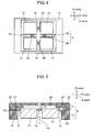
- Fig. 4 is a plan view of acceleration detection element 2 included in combined detection element 6.
- Fig. 5 is a sectional view showing an operating condition of combined detection element 6.
- Fig. 6 is a sectional view of another operating condition of combined detection element 6.
- Fig. 7 is a plan view of angular velocity detection element 4 included in combined detection element 6.
- acceleration detection element 2 included in combined detection element 6.
- weight parts 12 When acceleration ⁇ y is applied in the y-axis direction as shown in Fig. 6 , weight parts 12 start to be displaced in the y-axis direction and make connecting arms 10 cause distortion due to the acceleration ⁇ y. Weight parts 12, which are fixed to connecting arms 10, start to be displaced in the z-axis direction while being rotated.
- sensing portions 28 placed on connecting arms 10 detect distortions of connecting arms 10 (the change of state of connecting arms 10), thereby detecting acceleration.
- Notches 27 are formed in third arms 20 of angular velocity detection element 4, and third arms 20 are placed on fixing arm 8 of acceleration detection element 2. Therefore, even if weight parts 12 come into contact with third arms 20, the contact does not affect angular velocity detection element 4. More specifically, third arms 20 function as fixing arms for fixing acceleration detection element 2 and are not bent by the Coriolis force. Thus, third arms 20 do not affect the driving and vibration of weight parts 24 of angular velocity detection element 4, and do not reduce the sensitivity of angular velocity detection element 4.
- weight parts 12 which are fixed to connecting arms 10, start to be displaced in the z-axis direction while being rotated. However, weight parts 12 come into contact with angular velocity detection element 4 in notches 27 of angular velocity detection element 4, thereby being suppressed from moving upwardly.
- first arms 16 and second arms 18 of angular velocity detection element 4 are placed in the x- and y-axis directions, respectively, when x, y, and z are orthogonal axes.
- driving portions 30 When an AC voltage at the resonant frequency is applied to driving portions 30, the second arms 18 that include driving portions 30 start to drive and vibrate first, and then the remaining second arms 18 start to drive and vibrate.
- weight parts 24 also start to drive and vibrate in the direction perpendicular to second arms 18, that is, in the direction of driving and vibration shown by the solid arrows and the dotted arrows continuing thereto.
- second arms 18 and four weight parts 24 synchronously drive and vibrate in the direction perpendicular to opposing portions 22 of second arms 18.
- the direction of driving and vibration in angular velocity detection element 4 corresponds to the x-axis direction.
- Coriolis force is generated synchronously with the driving and vibration of weight parts 24 in the direction orthogonal to the direction of driving and vibration of weight parts 24, that is, in the Coriolis force direction shown by the solid arrows and the dotted arrows separate therefrom.
- Sensing portions 32 detect distortions due to the change of state of second arms 18, thereby detecting angular velocity.
- combined detection element 6 is formed by stacking acceleration detection element 2 and angular velocity detection element 4 on top of each other. This structure makes it unnecessary to individually place a detection element for detecting acceleration and a detection element for detecting angular velocity, thereby requiring a smaller mounting area and hence miniaturizing the combined sensor.
- the acceleration signal and the angular velocity signal detected by combined detection element 6 are electrically processed so that combined detection element 6 and the signal processor operate as the combined sensor.
- the combined sensor requires a smaller mounting area, thereby being miniaturized.
- angular velocity detection element 4 is stacked on acceleration detection element 2 in such a manner as to avoid contacting with weight parts 12 of acceleration detection element 2.
- angular velocity detection element 4 includes the suppressing portions for suppressing the upward movement of weight parts 12 of acceleration detection element 2. Therefore, even when acceleration exceeding the allowable vertical range of motion of weight parts 12 is applied, the suppressing portions for suppressing the movement of weight parts 12 limit the vertical range of motion within the specified range, thereby preventing the breakage of acceleration detection element 2. The suppression of the upward movement also prevents the breakage of angular velocity detection element 4.
- two opposite ones of four second arms 18 are provided with driving portions 30, and the other two second arms 18 are provided with sensing portions 32.
- at least one of the four second arms 18 may be provided with driving portion 30 and at least one of the four second arms 18 may be provided with sensing portion 32.
- the combined sensor of the present invention which can detect both acceleration and angular velocity, is miniaturized by reducing the mounting area, thereby being applicable to various electronic devices.
Landscapes
- Physics & Mathematics (AREA)
- General Physics & Mathematics (AREA)
- Engineering & Computer Science (AREA)
- Radar, Positioning & Navigation (AREA)
- Remote Sensing (AREA)
- Gyroscopes (AREA)
- Testing Or Calibration Of Command Recording Devices (AREA)
- Pressure Sensors (AREA)
Abstract
Description
- The present invention relates to a combined sensor for detecting angular velocity and acceleration, which is used in various electronic devices for attitude control or navigation of mobile objects such as aircrafts, automobiles, robots, marine vehicles, and other vehicles.
- Conventional combined sensors for detecting angular velocity and acceleration are generally formed of angular velocity sensors for detecting angular velocity and acceleration sensors for detecting acceleration.
- Therefore, in order to detect angular velocity and acceleration at the same time, an electronic device is required to have a plurality of angular velocity sensors and a plurality of acceleration sensors mounted on the substrate.
- In general, an angular velocity sensor detects angular velocity by vibrating a detection element that can be formed in different shapes such as tuning-fork-shaped, H-shaped, or T-shaped, and by electrically detecting distortion of the angular velocity detection element caused by the Coriolis force. An acceleration sensor has weight parts and detects acceleration by making an acceleration detection element compare the acceleration before and after the movement of the weight parts. A combined sensor includes, for example, an angular velocity sensor and an acceleration sensor so as to detect angular velocity and acceleration at the same time.
- These angular velocity sensors, acceleration sensors, and combined sensors are positioned along the respective axes of an attitude control system or a navigation system used in motor vehicles or other mobile objects.
- Such a conventional technique related to the present invention is shown, for example, in
Patent Documents 1 and 2 below. - In the aforementioned structure, the angular velocity sensors and the acceleration sensors are individually mounted on the substrate in such a manner as to be positioned along the respective axes for detecting angular velocity or acceleration. This requires a large mounting area, thus preventing the miniaturization of the combined sensor.
- Patent Document 1: Japanese Patent Unexamined Publication No.
2001-208546 - Patent Document 2: Japanese Patent Unexamined Publication No.
2001-74767 - In view of the above, an object of the present invention is to provide a combined sensor for detecting angular velocity and acceleration, which requires a smaller mounting area, thereby being miniaturized.
- The combined detection element of the present invention includes an acceleration detection element and an angular velocity detection element stacked on the acceleration detection element in such a manner as to avoid contacting with the weight parts of the acceleration detection element. In addition, the angular velocity detection element includes suppressing portions for suppressing the upward movement of the weight parts of the acceleration detection element. The combined detection element, which is thus structured by stacking the angular velocity detection element and the acceleration detection element on top of each other, requires a smaller mounting area, thereby being miniaturized.
- As described above, the angular velocity detection element is stacked on the acceleration detection element in such a manner as to avoid contacting with the weight parts of the acceleration detection element. In addition, the angular velocity detection element includes the suppressing portions for suppressing the upward movement of the weight parts of the acceleration detection element. Therefore, even when acceleration exceeding the allowable vertical movement of the weight parts is applied, the suppressing portions for suppressing the vertical movement of the weight parts limit the vertical range of motion within a specified range, thereby preventing the breakage of the acceleration detection element. The suppression of the vertical movement also prevents the breakage of the angular velocity detection element. The acceleration detection element detects an acceleration signal, which is then electrically processed, so that the acceleration detection element functions as an acceleration sensor. The angular velocity detection element detects an angular velocity signal, which is then electrically processed, so that the angular velocity detection element functions as an acceleration signal. Thus, in the combined detection element of the present invention, the angular velocity detection element and the acceleration detection element stacked on top of each other detect these signals which are then electrically processed. As a result, the detection elements function as an acceleration sensor and an angular velocity sensor, respectively, thereby functioning as a combined sensor including an acceleration sensor and an angular velocity sensor.
-
-
Fig. 1 is an exploded perspective view of a combined detection element according to an embodiment of the present invention. -
Fig. 2 is a perspective view of the combined detection element according to the embodiment of the present invention. -
Fig. 3 is a sectional view of the combined detection element according to the embodiment of the present invention taken along line 3-3 ofFig. 2 . -
Fig. 4 is a plan view of an acceleration detection element included in the combined detection element according to the embodiment of the present invention, showing an operating condition of the combined detection element. -
Fig. 5 is a sectional view showing an operating condition of the combined detection element according to the embodiment of the present invention. -
Fig. 6 is a sectional view showing another operating condition of the combined detection element according to the embodiment of the present invention. -
Fig. 7 is a plan view of an angular velocity detection element included in the combined detection element according to the embodiment of the present invention, showing an operating condition of the combined detection element. -
- 2
- acceleration detection element
- 4
- angular velocity detection element
- 6
- combined detection element
- 8
- fixing arm
- 10
- connecting arm
- 12, 24
- weight part
- 16
- first arm
- 18
- second arm
- 19
- support portion
- 20
- third arm
- 22
- opposing portion
- 23
- groove
- 25
- suppressing portion
- 26
- recess
- 27
- notch
- 28, 32
- sensing portion
- 30
- driving portion
- An embodiment of the present invention is described as follows with reference to drawings. In the drawings, some components are shown in an enlarged scale for easier understanding. The same components are referred to with the same numerals and hence the description of these components may be omitted.
-
Fig. 1 is an exploded perspective view of a combined detection element which forms a combined sensor according to an embodiment of the present invention.Fig. 2 is a perspective view of the combined detection element.Fig. 3 is a sectional view of the combined detection element taken along line 2A-2A ofFig. 2 . The combined sensor of the present invention includes a combined detection element and a signal processor (not shown) for electrically processing a detection signal received from the combined detection element. - The combined sensor according to the embodiment shown in
Figs. 1 to 3 includes combineddetection element 6 havingacceleration detection element 2 and angularvelocity detection element 4. -
Acceleration detection element 2 includes frame-like fixing arm 8 fixed to a mounting substrate, four connectingarms 10 connected together at one end and connected to fixingarm 8 at the other end, andweight parts 12 used for detecting acceleration.Weight parts 12 are arranged between four connectingarms 10 and connected to one end of each of four connectingarms 10. Four connectingarms 10 can be bent due to the movement ofweight parts 12. - Angular
velocity detection element 4 includes two first orthogonal arms, two second orthogonal arms, andsupport portion 19. The first orthogonal arms are each T-shaped in which onefirst arm 16 is sandwiched in a substantially orthogonal direction between twosecond arms 18 and connected thereto. The two second orthogonal arms each consist of onefirst arm 16 and onethird arm 20 connected in a substantially orthogonal direction thereto.Support portion 19 supports at its center the two adjacent first orthogonal arms. The ends of each ofthird arms 20 extend at right angles from the main portions ofthird arms 20 so as to be connected together in a frame shape. -
Second arms 18 include opposingportions 22 bent to face the main portions ofsecond arms 18, and the ends ofsecond arms 18 are connected to weightparts 24, which are used for detecting angular velocity and havegrooves 23. - As shown in
Figs. 2 and 3 , angularvelocity detection element 4 is stacked onacceleration detection element 2 in such a manner as to avoid contacting withweight parts 12 ofacceleration detection element 2. In addition, angularvelocity detection element 4 includes suppressing portions 25 (described later) for suppressing the upward movement ofweight parts 12 ofacceleration detection element 2. Angularvelocity detection element 4 further includesrecess 26 on a surface thereof facingweight parts 12 ofacceleration detection element 2 so as to avoid contacting withweight parts 12. At least part ofrecess 26 has a depth (D) not exceeding the vertical range of motion (H) ofweight parts 12. This structure forms suppressingportions 25 for suppressing the upward movement ofweight parts 12 ofacceleration detection element 2. - More specifically, as shown in
Fig. 3 ,third arms 20 of angularvelocity detection element 4 are fixedly stacked on fixingarm 8 ofacceleration detection element 2.Weight parts 24,first arms 16, andsecond arms 18 are made thinner thanthird arms 20.Third arms 20 are partially cut to formnotches 27, which have a depth (D) not exceeding the vertical range of motion (H) ofweight parts 12 ofacceleration detection element 2. - In combined
detection element 6, four connectingarms 10 function as arms to be bent due to the movement ofweight parts 12, andacceleration detection element 2 detects acceleration from the change of state of connectingarms 10. As shown inFig. 1 , four connectingarms 10 havesensing portions 28 for detecting the change of state of connectingarms 10.Sensing portions 28 are sensing electrode portions for detecting distortions of connectingarms 10, and can be formed of piezoresistive or piezoelectric elements. -
Second arms 18 function as driving-vibration arms and also as arms to be bent by the Coriolis force. Therefore, angularvelocity detection element 4 detects angular velocity from the change of state ofsecond arms 18. In angularvelocity detection element 4, two opposite ones of foursecond arms 18 are provided nearsupport portion 19 with drivingportions 30 for driving and vibrating theirweight parts 24. Drivingportions 30 are driving electrode portions for driving and vibrating the twosecond arms 18 and hence driving and vibrating theirweight parts 24. The driving electrode portions are each formed of upper and lower electrodes with a piezoelectric body interposed therebetween. The other twosecond arms 18 are provided nearsupport portion 19 withsensing portions 32 for detecting the change of state of the twosecond arms 18.Sensing portions 32 are sensing electrode portions for detecting distortions of the twosecond arms 18, and can be formed of piezoresistive or piezoelectric elements. -
Figs. 4, 5 , and7 show operating conditions of combineddetection element 6.Fig. 4 is a plan view ofacceleration detection element 2 included in combineddetection element 6.Fig. 5 is a sectional view showing an operating condition of combineddetection element 6.Fig. 6 is a sectional view of another operating condition of combineddetection element 6.Fig. 7 is a plan view of angularvelocity detection element 4 included in combineddetection element 6. - The following is a description of the operation of
acceleration detection element 2 included in combineddetection element 6. - It is assumed as shown in
Figs. 4 to 6 that four connectingarms 10 ofacceleration detection element 2 are placed in the x- and y-axis directions when x, y, and z are orthogonal axes. When acceleration αz is applied in the z-axis direction as shown inFig. 5 ,weight parts 12 start to be displaced in the z-axis direction and make connectingarms 10 cause distortion due to the acceleration αz. - When acceleration αy is applied in the y-axis direction as shown in
Fig. 6 ,weight parts 12 start to be displaced in the y-axis direction and make connectingarms 10 cause distortion due to the acceleration αy.Weight parts 12, which are fixed to connectingarms 10, start to be displaced in the z-axis direction while being rotated. - As shown in
Fig. 4 ,sensing portions 28 placed on connectingarms 10 detect distortions of connecting arms 10 (the change of state of connecting arms 10), thereby detecting acceleration. - In
acceleration detection element 2, if excessive acceleration αz is applied in the z-axis direction as shown inFig. 5 ,weight parts 12 start to move in the z-axis direction, but come into contact with angularvelocity detection element 4 innotches 27 of angularvelocity detection element 4, thereby being suppressed from moving upwardly. This is becausenotches 27 have a depth (D) not exceeding the vertical range of motion (H) inrecess 26 ofweight parts 12 ofacceleration detection element 2. If the depth (D) ofnotches 27 exceeds the vertical range of motion (H) ofweight parts 12, connectingarms 10 connected to weightparts 12 may be broken althoughweight parts 12 do not come into contact with angularvelocity detection element 4. -
Notches 27 are formed inthird arms 20 of angularvelocity detection element 4, andthird arms 20 are placed on fixingarm 8 ofacceleration detection element 2. Therefore, even ifweight parts 12 come into contact withthird arms 20, the contact does not affect angularvelocity detection element 4. More specifically,third arms 20 function as fixing arms for fixingacceleration detection element 2 and are not bent by the Coriolis force. Thus,third arms 20 do not affect the driving and vibration ofweight parts 24 of angularvelocity detection element 4, and do not reduce the sensitivity of angularvelocity detection element 4. - Similarly, if excessive acceleration αy is applied in the y-axis direction as shown in
Fig. 6 ,weight parts 12, which are fixed to connectingarms 10, start to be displaced in the z-axis direction while being rotated. However,weight parts 12 come into contact with angularvelocity detection element 4 innotches 27 of angularvelocity detection element 4, thereby being suppressed from moving upwardly. - The following is a description of the operation of angular
velocity detection element 4 included in combineddetection element 6. - It is assumed as shown in
Fig. 7 thatfirst arms 16 andsecond arms 18 of angularvelocity detection element 4 are placed in the x- and y-axis directions, respectively, when x, y, and z are orthogonal axes. When an AC voltage at the resonant frequency is applied to drivingportions 30, thesecond arms 18 that include drivingportions 30 start to drive and vibrate first, and then the remainingsecond arms 18 start to drive and vibrate. As a result,weight parts 24 also start to drive and vibrate in the direction perpendicular tosecond arms 18, that is, in the direction of driving and vibration shown by the solid arrows and the dotted arrows continuing thereto. - After all, four
second arms 18 and fourweight parts 24 synchronously drive and vibrate in the direction perpendicular to opposingportions 22 ofsecond arms 18. The direction of driving and vibration in angularvelocity detection element 4 corresponds to the x-axis direction. When angular velocity is generated counterclockwise in the z axis, Coriolis force is generated synchronously with the driving and vibration ofweight parts 24 in the direction orthogonal to the direction of driving and vibration ofweight parts 24, that is, in the Coriolis force direction shown by the solid arrows and the dotted arrows separate therefrom. This allowssecond arms 18 to cause distortion due to the angular velocity generated counterclockwise in the z axis.Sensing portions 32 detect distortions due to the change of state ofsecond arms 18, thereby detecting angular velocity. - As described above, combined
detection element 6 is formed by stackingacceleration detection element 2 and angularvelocity detection element 4 on top of each other. This structure makes it unnecessary to individually place a detection element for detecting acceleration and a detection element for detecting angular velocity, thereby requiring a smaller mounting area and hence miniaturizing the combined sensor. The acceleration signal and the angular velocity signal detected by combineddetection element 6 are electrically processed so that combineddetection element 6 and the signal processor operate as the combined sensor. Thus, the combined sensor requires a smaller mounting area, thereby being miniaturized. - As mentioned above, angular
velocity detection element 4 is stacked onacceleration detection element 2 in such a manner as to avoid contacting withweight parts 12 ofacceleration detection element 2. In addition, angularvelocity detection element 4 includes the suppressing portions for suppressing the upward movement ofweight parts 12 ofacceleration detection element 2. Therefore, even when acceleration exceeding the allowable vertical range of motion ofweight parts 12 is applied, the suppressing portions for suppressing the movement ofweight parts 12 limit the vertical range of motion within the specified range, thereby preventing the breakage ofacceleration detection element 2. The suppression of the upward movement also prevents the breakage of angularvelocity detection element 4. - In angular
velocity detection element 4 of the combined sensor according to the embodiment of the present invention, two opposite ones of foursecond arms 18 are provided with drivingportions 30, and the other twosecond arms 18 are provided withsensing portions 32. Alternatively, however, at least one of the foursecond arms 18 may be provided with drivingportion 30 and at least one of the foursecond arms 18 may be provided withsensing portion 32. - The combined sensor of the present invention, which can detect both acceleration and angular velocity, is miniaturized by reducing the mounting area, thereby being applicable to various electronic devices.
Claims (4)
- A combined sensor comprising:a combined detection element including:an angular velocity detection element andan acceleration detection element,
the acceleration detection element including:a weight part andan arm connected to the weight part and to be bent, and
the angular velocity detection element including:a driving-vibration arm andan arm to be bent by Coriolis force, whereinthe angular velocity detection element is stacked on the acceleration detection element in such a manner as to avoid contacting with the weight part of the acceleration detection element; andthe angular velocity detection element has a suppressing portion for suppressing upward movement of the weight part of the acceleration detection element. - The combined sensor of claim 1, wherein
the angular velocity detection element includes a recess on a surface thereof facing the weight part of the acceleration detection element so as to avoid contacting with the weight part, at least part of the recess having a depth not exceeding a vertical range of motion of the weight part. - The combined sensor of claim 1, wherein
the angular velocity detection element includes two orthogonal arms each formed by connecting a first arm in a direction orthogonal to second arms, a support portion for supporting the two first arms, and two orthogonal arms each formed by connecting the first arm in a direction orthogonal to a third arm, wherein
the third arms are fixed to the acceleration detection element;
the weight part, the first arms, and the second arms are thinner than the third arms; and
the third arms are partially cut to form a recess having a depth not exceeding the vertical range of motion of the weight part of the acceleration detection element. - The combined sensor of claim 3, wherein
the acceleration detection element includes the arm connected to the weight part and to be bent, and a fixing arm to be fixed to a mounting substrate, and
the third arms of the angular velocity detection element are fixedly stacked on the fixing arm of the acceleration detection element.
Applications Claiming Priority (2)
| Application Number | Priority Date | Filing Date | Title |
|---|---|---|---|
| JP2006223806A JP4929918B2 (en) | 2006-08-21 | 2006-08-21 | Compound sensor |
| PCT/JP2007/065583 WO2008023573A1 (en) | 2006-08-21 | 2007-08-09 | Combined sensor |
Publications (2)
| Publication Number | Publication Date |
|---|---|
| EP2037285A1 true EP2037285A1 (en) | 2009-03-18 |
| EP2037285A4 EP2037285A4 (en) | 2012-11-14 |
Family
ID=39106660
Family Applications (1)
| Application Number | Title | Priority Date | Filing Date |
|---|---|---|---|
| EP07805914A Withdrawn EP2037285A4 (en) | 2006-08-21 | 2007-08-09 | Combined sensor |
Country Status (5)
| Country | Link |
|---|---|
| US (1) | US8061203B2 (en) |
| EP (1) | EP2037285A4 (en) |
| JP (1) | JP4929918B2 (en) |
| CN (1) | CN101501505B (en) |
| WO (1) | WO2008023573A1 (en) |
Cited By (2)
| Publication number | Priority date | Publication date | Assignee | Title |
|---|---|---|---|---|
| EP2667202A4 (en) * | 2011-01-20 | 2014-02-05 | Panasonic Corp | ACCELERATION SENSOR |
| EP3358357A4 (en) * | 2015-09-30 | 2019-11-06 | Hitachi Automotive Systems, Ltd. | SENSOR OF INERTIA |
Families Citing this family (13)
| Publication number | Priority date | Publication date | Assignee | Title |
|---|---|---|---|---|
| JP2008190931A (en) * | 2007-02-02 | 2008-08-21 | Wacoh Corp | Sensor that detects both acceleration and angular velocity |
| JP5789737B2 (en) * | 2009-11-24 | 2015-10-07 | パナソニックIpマネジメント株式会社 | Acceleration sensor |
| CN101865933A (en) * | 2010-06-07 | 2010-10-20 | 瑞声声学科技(深圳)有限公司 | Differential Capacitive Accelerometer |
| JP5505193B2 (en) * | 2010-08-17 | 2014-05-28 | シンフォニアテクノロジー株式会社 | Compound sensor, sensor unit |
| KR101299731B1 (en) * | 2012-05-29 | 2013-08-22 | 삼성전기주식회사 | Angular velocity sensor |
| KR101388814B1 (en) * | 2012-09-11 | 2014-04-23 | 삼성전기주식회사 | Angular Velocity Sensor |
| KR101366990B1 (en) * | 2012-12-28 | 2014-02-24 | 삼성전기주식회사 | Angular velocity sensor |
| KR101531093B1 (en) * | 2013-07-31 | 2015-06-23 | 삼성전기주식회사 | Acceleration Sensor and Angular Velocity Sensor |
| JP6464749B2 (en) | 2015-01-06 | 2019-02-06 | セイコーエプソン株式会社 | Physical quantity sensor, electronic device and mobile object |
| JP6372361B2 (en) * | 2015-01-16 | 2018-08-15 | 株式会社デンソー | Compound sensor |
| JP5833790B2 (en) * | 2015-07-03 | 2015-12-16 | 株式会社トライフォース・マネジメント | Power generation element |
| US11164197B2 (en) * | 2018-04-13 | 2021-11-02 | Shopper Scientist Llc | Shopping time allocated to product exposure in a shopping environment |
| CN111780899B (en) | 2019-04-04 | 2022-04-12 | 武汉杰开科技有限公司 | Composite sensor and manufacturing method thereof |
Family Cites Families (17)
| Publication number | Priority date | Publication date | Assignee | Title |
|---|---|---|---|---|
| JPH09196682A (en) * | 1996-01-19 | 1997-07-31 | Matsushita Electric Ind Co Ltd | Angular velocity sensor and acceleration sensor |
| JPH10239064A (en) * | 1997-02-27 | 1998-09-11 | Matsushita Electric Ind Co Ltd | Composite sensor of angular velocity and acceleration |
| JP2001074767A (en) | 1999-09-03 | 2001-03-23 | Matsushita Electric Ind Co Ltd | Acceleration sensor and method of manufacturing the same |
| JP2001208546A (en) | 1999-11-16 | 2001-08-03 | Matsushita Electric Ind Co Ltd | Angular velocity sensor |
| JP2002005951A (en) * | 2000-06-26 | 2002-01-09 | Denso Corp | Semiconductor dynamic quantity sensor and method of manufacturing the same |
| EP1366712A4 (en) * | 2001-03-06 | 2006-05-31 | Microstone Co Ltd | Body motion detector |
| JP2003014778A (en) * | 2001-04-26 | 2003-01-15 | Samsung Electronics Co Ltd | Vertical displacement measuring and driving structure and manufacturing method thereof |
| US6725719B2 (en) * | 2002-04-17 | 2004-04-27 | Milli Sensor Systems And Actuators, Inc. | MEMS-integrated inertial measurement units on a common substrate |
| CN1227535C (en) * | 2002-07-02 | 2005-11-16 | 中国科学院合肥智能机械研究所 | Six-axis acceleration sensor with double E-shaped circular diaphragm cross beam structure |
| US7335971B2 (en) * | 2003-03-31 | 2008-02-26 | Robert Bosch Gmbh | Method for protecting encapsulated sensor structures using stack packaging |
| JP2005098891A (en) * | 2003-09-25 | 2005-04-14 | Matsushita Electric Works Ltd | Electrostatic capacity type sensor |
| JP2005283393A (en) * | 2004-03-30 | 2005-10-13 | Fujitsu Media Device Kk | Inertial sensor |
| JP2006125887A (en) * | 2004-10-26 | 2006-05-18 | Fujitsu Media Device Kk | Acceleration sensor |
| JP2006133004A (en) * | 2004-11-04 | 2006-05-25 | Matsushita Electric Ind Co Ltd | Angular velocity sensor |
| JP4774733B2 (en) * | 2004-12-03 | 2011-09-14 | パナソニック株式会社 | Compound sensor |
| JP4702942B2 (en) * | 2005-10-14 | 2011-06-15 | Necトーキン株式会社 | Vibrating gyro element and vibrating gyro |
| JP2007248328A (en) * | 2006-03-17 | 2007-09-27 | Matsushita Electric Ind Co Ltd | Compound sensor |
-
2006
- 2006-08-21 JP JP2006223806A patent/JP4929918B2/en not_active Expired - Fee Related
-
2007
- 2007-08-09 EP EP07805914A patent/EP2037285A4/en not_active Withdrawn
- 2007-08-09 US US12/375,109 patent/US8061203B2/en not_active Expired - Fee Related
- 2007-08-09 CN CN2007800291005A patent/CN101501505B/en not_active Expired - Fee Related
- 2007-08-09 WO PCT/JP2007/065583 patent/WO2008023573A1/en not_active Ceased
Cited By (2)
| Publication number | Priority date | Publication date | Assignee | Title |
|---|---|---|---|---|
| EP2667202A4 (en) * | 2011-01-20 | 2014-02-05 | Panasonic Corp | ACCELERATION SENSOR |
| EP3358357A4 (en) * | 2015-09-30 | 2019-11-06 | Hitachi Automotive Systems, Ltd. | SENSOR OF INERTIA |
Also Published As
| Publication number | Publication date |
|---|---|
| WO2008023573A1 (en) | 2008-02-28 |
| JP2008046057A (en) | 2008-02-28 |
| US20090183569A1 (en) | 2009-07-23 |
| EP2037285A4 (en) | 2012-11-14 |
| US8061203B2 (en) | 2011-11-22 |
| CN101501505B (en) | 2011-07-20 |
| JP4929918B2 (en) | 2012-05-09 |
| CN101501505A (en) | 2009-08-05 |
Similar Documents
| Publication | Publication Date | Title |
|---|---|---|
| US8061203B2 (en) | Combined sensor | |
| EP2056068B1 (en) | Inertia force sensor | |
| EP2899502B1 (en) | Inertial force sensor | |
| EP2113744A1 (en) | Inertia force sensor and composite sensor for detecting inertia force | |
| EP2000769A9 (en) | Inertia force sensor | |
| US8074517B2 (en) | Inertia force sensor | |
| EP2385343B1 (en) | Inertial force sensor and detecting element used for same | |
| JP4687085B2 (en) | Compound sensor | |
| JP4774733B2 (en) | Compound sensor | |
| JP2006162314A (en) | Compound sensor | |
| JP4858215B2 (en) | Compound sensor | |
| JP5125138B2 (en) | Compound sensor | |
| JP4626858B2 (en) | Angular velocity sensor element | |
| JP2007198778A (en) | Inertial force sensor | |
| JP2008261771A (en) | Inertial force sensor | |
| JP2007198774A (en) | Inertial force sensor | |
| JP2007198779A (en) | Inertial force sensor | |
| JP2008157706A (en) | Sensor | |
| JP2007198780A (en) | Inertial force sensor | |
| JP2007198776A (en) | Inertial force sensor | |
| JP2008261772A (en) | Inertial force sensor | |
| JP2008209253A (en) | Angular velocity sensor | |
| JP2007198777A (en) | Inertial force sensor | |
| JP2009192234A (en) | Sensor |
Legal Events
| Date | Code | Title | Description |
|---|---|---|---|
| PUAI | Public reference made under article 153(3) epc to a published international application that has entered the european phase |
Free format text: ORIGINAL CODE: 0009012 |
|
| 17P | Request for examination filed |
Effective date: 20081212 |
|
| AK | Designated contracting states |
Kind code of ref document: A1 Designated state(s): AT BE BG CH CY CZ DE DK EE ES FI FR GB GR HU IE IS IT LI LT LU LV MC MT NL PL PT RO SE SI SK TR |
|
| AX | Request for extension of the european patent |
Extension state: AL BA HR MK RS |
|
| DAX | Request for extension of the european patent (deleted) | ||
| RBV | Designated contracting states (corrected) |
Designated state(s): DE FR GB |
|
| A4 | Supplementary search report drawn up and despatched |
Effective date: 20121016 |
|
| STAA | Information on the status of an ep patent application or granted ep patent |
Free format text: STATUS: THE APPLICATION IS DEEMED TO BE WITHDRAWN |
|
| 18D | Application deemed to be withdrawn |
Effective date: 20130514 |