EP2037240A1 - Optical sensor for detecting peripheral light and liquid crystal display device using the same - Google Patents
Optical sensor for detecting peripheral light and liquid crystal display device using the same Download PDFInfo
- Publication number
- EP2037240A1 EP2037240A1 EP08164118A EP08164118A EP2037240A1 EP 2037240 A1 EP2037240 A1 EP 2037240A1 EP 08164118 A EP08164118 A EP 08164118A EP 08164118 A EP08164118 A EP 08164118A EP 2037240 A1 EP2037240 A1 EP 2037240A1
- Authority
- EP
- European Patent Office
- Prior art keywords
- transistors
- peripheral light
- optical sensor
- coupled
- transistor
- Prior art date
- Legal status (The legal status is an assumption and is not a legal conclusion. Google has not performed a legal analysis and makes no representation as to the accuracy of the status listed.)
- Granted
Links
- 230000002093 peripheral effect Effects 0.000 title claims abstract description 96
- 230000003287 optical effect Effects 0.000 title claims abstract description 55
- 239000004973 liquid crystal related substance Substances 0.000 title claims description 40
- 239000011159 matrix material Substances 0.000 claims description 14
- 210000002858 crystal cell Anatomy 0.000 claims description 10
- 238000001514 detection method Methods 0.000 claims description 9
- 238000000034 method Methods 0.000 claims description 9
- 230000003321 amplification Effects 0.000 description 3
- 230000015556 catabolic process Effects 0.000 description 3
- 238000006731 degradation reaction Methods 0.000 description 3
- 238000003199 nucleic acid amplification method Methods 0.000 description 3
- 239000003990 capacitor Substances 0.000 description 2
- 210000004027 cell Anatomy 0.000 description 1
- 230000008878 coupling Effects 0.000 description 1
- 238000010168 coupling process Methods 0.000 description 1
- 238000005859 coupling reaction Methods 0.000 description 1
- 238000004519 manufacturing process Methods 0.000 description 1
- 238000012986 modification Methods 0.000 description 1
- 230000004048 modification Effects 0.000 description 1
- 238000002834 transmittance Methods 0.000 description 1
- 230000000007 visual effect Effects 0.000 description 1
- 230000016776 visual perception Effects 0.000 description 1
Images


Classifications
-
- G—PHYSICS
- G01—MEASURING; TESTING
- G01J—MEASUREMENT OF INTENSITY, VELOCITY, SPECTRAL CONTENT, POLARISATION, PHASE OR PULSE CHARACTERISTICS OF INFRARED, VISIBLE OR ULTRAVIOLET LIGHT; COLORIMETRY; RADIATION PYROMETRY
- G01J1/00—Photometry, e.g. photographic exposure meter
- G01J1/42—Photometry, e.g. photographic exposure meter using electric radiation detectors
- G01J1/44—Electric circuits
-
- G—PHYSICS
- G02—OPTICS
- G02F—OPTICAL DEVICES OR ARRANGEMENTS FOR THE CONTROL OF LIGHT BY MODIFICATION OF THE OPTICAL PROPERTIES OF THE MEDIA OF THE ELEMENTS INVOLVED THEREIN; NON-LINEAR OPTICS; FREQUENCY-CHANGING OF LIGHT; OPTICAL LOGIC ELEMENTS; OPTICAL ANALOGUE/DIGITAL CONVERTERS
- G02F1/00—Devices or arrangements for the control of the intensity, colour, phase, polarisation or direction of light arriving from an independent light source, e.g. switching, gating or modulating; Non-linear optics
- G02F1/01—Devices or arrangements for the control of the intensity, colour, phase, polarisation or direction of light arriving from an independent light source, e.g. switching, gating or modulating; Non-linear optics for the control of the intensity, phase, polarisation or colour
- G02F1/13—Devices or arrangements for the control of the intensity, colour, phase, polarisation or direction of light arriving from an independent light source, e.g. switching, gating or modulating; Non-linear optics for the control of the intensity, phase, polarisation or colour based on liquid crystals, e.g. single liquid crystal display cells
- G02F1/133—Constructional arrangements; Operation of liquid crystal cells; Circuit arrangements
Definitions
- the present invention relates to an optical sensor for detecting peripheral light and a liquid crystal display device using the same, and, in particular, to an optical sensor for detecting peripheral light and a liquid crystal display device using the same capable of stably obtaining output current while minimizing a mounting space.
- LCD liquid crystal display
- FED field emission display
- PDP plasma display panel
- OLED organic light emitting display
- Liquid crystal display devices have advantages of slimness, lightweight, low power consumption, etc., so that they may overcome the disadvantages of existing cathode ray tubes.
- Liquid crystal display devices may be mounted in mobile equipment, such as mobile phones, personal digital assistants (PDAs), etc., as well as monitors, televisions, etc., which are middle and large-sized products.
- Such liquid crystal displays are transparent type display devices and display desired images by controlling the amount of light transmitted through liquid crystal layers by utilizing the refractive index anisotropy of liquid crystal molecules.
- a backlight radiates light with constant brightness to each pixel unit.
- the power consumption of the backlight remains high due to the supply of light with constant brightness to each pixel unit.
- the backlight consumes 80% or more of the power consumed for operating the liquid crystal display device.
- An aspect of an embodiment of the present invention is directed toward an optical sensor for detecting peripheral light, and a liquid crystal display device utilizing the same, that is capable of stably obtaining output current while minimizing a mounting space.
- An embodiment of the present invention provides an optical sensor for detecting peripheral light including: at least two first transistors coupled in parallel between an output line and base power supply for detecting an intensity of peripheral light; and at least two second transistors positioned at a side of the first transistors and between the first transistors and a voltage source.
- the voltage source may be set to a higher voltage value than that of the base power supply.
- First electrodes and gate electrodes of the first transistors may be coupled to the base power supply and second electrodes of the first transistors may be coupled to the output line.
- the first transistors may be adapted to control an amount of current flowing into the output line corresponding to the intensity of peripheral light incident on their gate electrodes.
- First electrodes of the second transistors may be coupled to the output line, second electrodes of the second transistors may be coupled to the voltage source, and gate electrodes of the second transistors may be coupled to the base power supply.
- a liquid crystal display device including: a pixel unit including a plurality of liquid crystal cells; at least one optical sensor for detecting peripheral light and outputting a peripheral light signal corresponding to an intensity of the peripheral light; a backlight for supplying light to the pixel unit; and a backlight driver for controlling a brightness of light generated from the backlight in accordance with the peripheral light signal
- the optical sensor includes: at least two first transistors positioned at an opening part of a black matrix and coupled in parallel between an output line and base power supply for detecting an intensity of peripheral light; and at least two second transistors positioned at a side of the first transistors and overlapping with the black matrix, and between the first transistors and a voltage source.
- an optical sensor for detecting peripheral light including: a first detection transistor and a second detection transistor, the first and second detection transistors being coupled in parallel between an output line and a base power supply for detecting an intensity of peripheral light; a first compensation transistor coupled between the first detection transistor and a voltage source; and a second compensation transistor coupled between the second detection transistor and the voltage source.
- the voltage source may be set to a higher voltage value than that of the base power supply.
- the base power supply may be a ground.
- the first electrodes and gate electrodes of the first and second detection transistors may be coupled to the base power supply and second electrodes of the first and second detection transistors are coupled to the output line.
- the first and second detection transistors may be adapted to control an amount of current flowing into the output line in accordance with the intensity of peripheral light incident on their gate electrodes.
- the first electrodes of the first and second compensation transistors may be coupled to the output line, second electrodes of the first and second compensation transistors are coupled to the voltage source, and gate electrodes of the first and second compensation transistors are coupled to the base power supply.
- FIG. 1 is a schematic view showing a liquid crystal display device according to an embodiment of the present invention
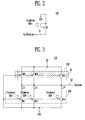
- FIG. 2 is a schematic view showing an embodiment of an optical sensor for detecting peripheral light, as shown in FIG. 1 ;
- FIG. 3 is a schematic view showing another embodiment of the optical sensor for detecting peripheral light, as shown in FIG. 1 ;
- FIG. 4A and 4B are schematic views showing a compensation concept of the characteristic deviations of transistors in accordance with embodiments of the present invention, as shown in FIG. 3 .
- FIG. 1 is a schematic view showing a liquid crystal display device according to an embodiment of the present invention.
- FIG. 1 shows an active matrix liquid crystal display device, but the present invention is not limited thereto.
- the liquid crystal display device includes a pixel unit (or display region) 20, a scan driver 40, a data driver 60, a gamma voltage supplier 80, a timing controller 100, an optical sensor 110 for detecting peripheral light, a backlight driver 120, and a backlight 140.
- the pixel unit 20 includes a plurality of liquid crystal cells Clc arranged in a matrix type at crossing regions of data lines D1 to Dm and scan lines S1 to Sn.
- at least one TFT and at least one storage capacitor Cst are formed in each liquid crystal cell Clc.
- the TFT supplies data signals supplied from the data line D to the liquid crystal cells Clc corresponding to scan signals supplied from the scan line S.
- the storage capacitor Cst is formed between a pixel electrode of the liquid crystal cell Clc and a pre-scan line (or a previous scan line) S or between the pixel electrode of the liquid crystal cell Clc and a common electrode line so that it can constantly maintain the voltage of the liquid crystal cell Clc during one frame.
- a black matrix 30 is formed between the respective liquid crystal cells Clc and at an outer part of the pixel unit 20 so that light incident from neighboring cells or the outer part of the pixel unit 20 is absorbed, thereby preventing (or reducing) the degradation of contrast.
- the scan driver 40 sequentially supplies the scan signals to the scan lines S1 to Sn corresponding to a scan control signal SCS supplied from the timing controller 100 to select a line of (or a horizontal line of) the pixel units 20 supplied with the data signals.
- the data driver 60 converts digital video data R, G, and B into analog gamma voltages corresponding to gray level values, that is, the data signals, utilizing a scan control signal DCS supplied from the timing controller 100.
- the data signals converted in the data driver 60 are supplied to the data lines D 1 to Dm.
- the gamma voltage supplier 80 supplies a plurality of gamma voltages to the data driver 60.
- the timing controller 100 generates the scan control signal SCS and the data control signal DCS for controlling the scan driver 40 and the data driver 60, respectively, using vertical and horizontal synchronization signals Vsync and Hsync and an externally supplied clock signal CLK.
- the scan control signal SCS for controlling the scan driver 40 has a gate start pulse, a gate shift clock, a gate output enable signal, etc.
- the data control signal DCS for controlling the data driver 60 has a source start pulse, a source shift clock, a source output enable signal, a polarity signals, etc.
- the timing controller 100 processes the externally supplied data R, G, and B and supplies them to the data driver 60.
- the optical sensor 110 for detecting peripheral light is formed at an edge portion of the pixel unit 20, that is, at a region of the black matrix 30.
- the optical sensor 110 generates the peripheral light signal corresponding to the intensity of peripheral light and then supplies the peripheral light signal to the backlight driver 120.
- the optical sensor 110 is positioned at a region of an opening part 35 of the black matrix 30.
- the backlight driver 120 supplies driving voltage (or driving current) to the backlight 140 to drive the backlight 140.
- the backlight driver 120 changes the value of the driving voltage (or driving current) corresponding to the peripheral light signal to control the brightness of light generated from the backlight 140. For example, in the case where the backlight driver 120 receives the peripheral light signal from the optical sensor 110 corresponding to a weak intensity peripheral light, the driving voltage (or driving current) of the backlight 140 is lowered by a value (e.g., a predetermined value) corresponding to the intensity of peripheral light so that the brightness of light generated from the backlight 140 is reduced, thereby reducing power consumption.
- a value e.g., a predetermined value
- the backlight driver 120 receives the peripheral light signal from the optical sensor 110 corresponding to an intensity of peripheral light above a set (or predetermined) intensity
- the driving voltage (or driving current) of the backlight 140 is not changed so that the brightness of light generated from the backlight 140 is not reduced, thereby preventing (or reducing) a degradation in a visual perception characteristic of the pixel unit 20.
- FIG. 1 shows only one optical sensor 110 for detecting peripheral light, but the present invention is not limited thereto.
- a plurality of optical sensors for detecting peripheral light 110 may be included in the region of the black matrix 30.
- the number of the optical sensors 110 for detecting peripheral light may be suitably established.
- the backlight 140 generates light corresponding to the driving voltage (or driving current) supplied from the backlight driver 120, and then supplies it to the pixel unit 20.
- the optical sensor 110 for detecting peripheral light to detect the intensity of peripheral light, making it possible to control the brightness of light generated from the backlight 140 corresponding to the peripheral light. As a result, power consumption may be reduced.
- the intensity of peripheral light above a set (or predetermined) value is detected, the brightness of light generated from the backlight 140 is not reduced so that degradation in a visual characteristic can be reduced or prevented.
- FIG. 2 is a schematic view showing an embodiment of an optical sensor for detecting peripheral light, as shown in FIG. 1 .
- the optical sensor 110 for detecting peripheral light includes a transistor M coupled between an output line L1 for outputting the peripheral light signal and a base power supply VSS.
- the first electrode of the transistor M is coupled to the base power supply VSS, which is set, e.g., to ground (GND) voltage, and the second electrode at the transistor Mis coupled to the output line L1 of the optical sensor 110 for detecting peripheral light.
- the first electrode and the second electrode are different electrodes from each other.
- the second electrode is a drain electrode.
- the output line L1 is utilized for detecting the size of current flowing into the optical sensor 110 for detecting peripheral light, as well as receives a pulse wave signal VP.
- the output line L1 receives the pulse wave signal VP swing between a first voltage that is a ground voltage and a second voltage (for example, a voltage of 2V) with a voltage value higher than the ground voltage and at substantially the same time, is for detecting the size of current flowing into the transistor M.
- a first voltage that is a ground voltage and a second voltage (for example, a voltage of 2V) with a voltage value higher than the ground voltage and at substantially the same time, is for detecting the size of current flowing into the transistor M.
- a gate electrode of the transistor M is coupled to its first electrode and the base power supply VSS. That is, the gate electrode of the transistor M is coupled to the first electrode for receiving a voltage value lower than that of its second electrode so that it is coupled in a reverse diode-connection form.
- the gate electrode of the transistor M is positioned at the opening part 35 of the black matrix 30 to receive peripheral light.
- the current flowing into the output line L1 of the optical sensor 110 for detecting peripheral light is measured, making it possible to detect the intensity of peripheral light. That is, the current flowing into the output line L1 of the optical sensor 110 for detecting peripheral light is set to the peripheral light signal. Since the transistor M of the optical sensor 110 for detecting peripheral light is coupled in the reverse diode-connection form, the current value corresponding to the intensity of peripheral light is changed in a substantially linear form to assure its reliability.
- the optical sensor 110 for detecting peripheral light is implemented with only one transistor M as above, the current output to the output line L1 may be weak, so that the peripheral light cannot be effectively detected.
- an embodiment of the present invention proposes an optical sensor 110' for detecting peripheral light capable of generating sufficient output current without having a separate amplification circuit.
- FIG. 3 is a schematic view showing another embodiment of the optical sensor for detecting peripheral light, as shown in FIG. 1 .
- the optical sensor 110' for detecting peripheral light is divided into a compensator 200 and a sensor 202.
- the sensor 202 includes two or more first transistors M11 to M1n, where n is an integer, coupled in parallel between an output line L2 for outputting the peripheral light signal and the base power supply VSS.
- the first electrodes of the first transistors M11 to M1n are coupled to the base power supply VSS and the second electrodes thereof are coupled to the output line L2 of the optical sensor 110' for detecting peripheral light. Also, the gate electrodes of the first transistors M11 to M1n are coupled to their first electrode and the base power supply VSS. That is, the first transistors M11 to M1n are coupled in parallel and the respective first transistors M11 to M1N are coupled in a reverse diode-connection form.
- the gate electrodes of the first transistors M11 to M1n are positioned at the opening part 35 of the black matrix 30 so that they can receive the peripheral light.
- current corresponding to the intensity of peripheral light flows from the second electrode to the first electrode (reverse current).
- current which is the sum of currents (i1 to in) flowing into each of the first transistors M11 to M1n, flows into the output line L2.
- the current flowing into the output line L2 is the sum of current flowing into the first transistors M11 to M1n. Therefore, the peripheral light can be stably detected using the current flowing into the output line L2 of the optical sensor 110' for detecting peripheral light without having a separate amplification circuit. Also, in an embodiment of the present invention, since the first transistors M11 to M1n are concurrently (or simultaneously) formed with the TFT, a manufacturing process and a design are simplified.
- the size of a light entrance part can be reduced, as compared to the optical sensor for detecting peripheral light having the single large transistor M for obtaining the same output characteristics. Further, the light entrance part on which light is incident can be dispersed, making it possible to reduce the likelihood of or prevent the optical sensor 110' for detecting peripheral light from being recognized by a human eye.
- the compensator 200 includes second transistors M21 to M2n, where n is an integer, coupled between each of the first transistors M11 to M1n and the second voltage source VP (power supply higher than the VSS).
- the number of second transistors M21 to M2n is preferably the same as the number of first transistors M11 to M1n such that each second transistor M21 to M2n is coupled to a single respective first transistor M11 to M1n.
- the first electrodes of the second transistors M21 to M2n are coupled to the output line L2 and the second electrodes of the second transistors M21 to M2n are coupled to the second voltage source VP.
- the gate electrodes of the second transistors M21 to M2n are coupled to the base power supply VSS.
- the second transistors M21 to M2n are utilizied to compensate for process deviations of the first transistors M11 to M1n. That is, the currents flowing to the first transistors M11 to M1N corresponding to the peripheral light for each region of the liquid crystal display device are different due to process deviations.
- the second transistors M21 to M2n are positioned between each of the first transistors M11 to M1n and the second voltage source VP so that the currents flowing into the output line L2 corresponding to the peripheral light are controlled to be the same (or substantially the same) for each region, regardless of process deviations of the first transistors M11 and M1n.
- the resistance of the first and second transistors M11 and M21 in a first liquid crystal display device may be 20 ⁇ , as shown in FIG. 4A . It is assumed that since the first and second transistors M11 and M21 are formed utilizing the same process or substantially the same process, they have substantially similar characteristics. Thereafter, if the resistance of the first transistor M11 is reduced to 10 ⁇ by peripheral light, current corresponding to the resistance ratio of 20 ⁇ to 10 ⁇ flows into the output line L2.
- the resistance of the first and second transistors M11' and M21' in a second liquid crystal display device or in another region of the first display device may have 10 ⁇ , as shown in FIG. 4B . Thereafter, if the resistance of the first transistor M11' is reduced to 5 ⁇ by peripheral light, the current corresponding to the resistance ratio of 10 ⁇ to 5 ⁇ flows into the output line L2.
- each first transistor M11 to M1n is preferably the same as its respective second transistor M21 to M2n. That is, the current flowing into the output line L2 corresponding to peripheral light in the first liquid crystal panel and the second liquid crystal panel or in another region of the first liquid crystal panel can be substantially similar, regardless of the deviations of the transistors M11 and M21.
- the second transistors M21 to M2n overlap with the black matrix 30 to have substantially constant characteristics, regardless of the peripheral light.
- the second transistors M21 to M2n are positioned to overlap with the black matrix 30, there is an advantage in that the second transistors M21 to M2n are not externally visible.
- the second transistors M21 to M2n of an embodiment of the present invention are mounted on the upper and/or lower sides of the first transistors M11 to M1n.
- the mounting area can be reduced or minimized. As a result, space utilization can be increased.
- all the transistors M are an N-type in FIG. 3 , but the present invention is not limited thereto.
- the transistors M can be a P-type.
- the optical sensor for detecting peripheral light can supply sufficient current without having a separate amplification circuit.
- the second transistors for compensating the characteristic deviations of the first transistors are on the upper and/or lower sides of the first transistors, space utilization can be increased or maximized.
Landscapes
- Physics & Mathematics (AREA)
- General Physics & Mathematics (AREA)
- Nonlinear Science (AREA)
- Spectroscopy & Molecular Physics (AREA)
- Optics & Photonics (AREA)
- Crystallography & Structural Chemistry (AREA)
- Chemical & Material Sciences (AREA)
- Mathematical Physics (AREA)
- Liquid Crystal (AREA)
- Control Of Indicators Other Than Cathode Ray Tubes (AREA)
- Liquid Crystal Display Device Control (AREA)
- Photometry And Measurement Of Optical Pulse Characteristics (AREA)
- Devices For Indicating Variable Information By Combining Individual Elements (AREA)
Abstract
Description
- The present invention relates to an optical sensor for detecting peripheral light and a liquid crystal display device using the same, and, in particular, to an optical sensor for detecting peripheral light and a liquid crystal display device using the same capable of stably obtaining output current while minimizing a mounting space.
- Various flat panel display devices capable of reducing weight and volume, which are disadvantages of cathode ray tubes, have been developed. These include a liquid crystal display (LCD), a field emission display (FED), a plasma display panel (PDP), an organic light emitting display (OLED), etc.
- Liquid crystal display devices have advantages of slimness, lightweight, low power consumption, etc., so that they may overcome the disadvantages of existing cathode ray tubes. Liquid crystal display devices may be mounted in mobile equipment, such as mobile phones, personal digital assistants (PDAs), etc., as well as monitors, televisions, etc., which are middle and large-sized products. Such liquid crystal displays are transparent type display devices and display desired images by controlling the amount of light transmitted through liquid crystal layers by utilizing the refractive index anisotropy of liquid crystal molecules.
- In such liquid crystal display devices, a backlight radiates light with constant brightness to each pixel unit. However, even though a large amount of light is not required when a peripheral environment is dark, the power consumption of the backlight remains high due to the supply of light with constant brightness to each pixel unit. The backlight consumes 80% or more of the power consumed for operating the liquid crystal display device.
- Therefore, there is a need for a method of effectively controlling the light of a backlight by utilizing an optical sensor for detecting peripheral light, and a method of improving the output characteristics of the optical sensor for detecting peripheral light to be able to effectively detect the peripheral light.
- An aspect of an embodiment of the present invention is directed toward an optical sensor for detecting peripheral light, and a liquid crystal display device utilizing the same, that is capable of stably obtaining output current while minimizing a mounting space.
- An embodiment of the present invention provides an optical sensor for detecting peripheral light including: at least two first transistors coupled in parallel between an output line and base power supply for detecting an intensity of peripheral light; and at least two second transistors positioned at a side of the first transistors and between the first transistors and a voltage source.
- The voltage source may be set to a higher voltage value than that of the base power supply.
- First electrodes and gate electrodes of the first transistors may be coupled to the base power supply and second electrodes of the first transistors may be coupled to the output line.
- The first transistors may be adapted to control an amount of current flowing into the output line corresponding to the intensity of peripheral light incident on their gate electrodes.
- First electrodes of the second transistors may be coupled to the output line, second electrodes of the second transistors may be coupled to the voltage source, and gate electrodes of the second transistors may be coupled to the base power supply.
- Another embodiment of the present invention provides a liquid crystal display device including: a pixel unit including a plurality of liquid crystal cells; at least one optical sensor for detecting peripheral light and outputting a peripheral light signal corresponding to an intensity of the peripheral light; a backlight for supplying light to the pixel unit; and a backlight driver for controlling a brightness of light generated from the backlight in accordance with the peripheral light signal, wherein the optical sensor includes: at least two first transistors positioned at an opening part of a black matrix and coupled in parallel between an output line and base power supply for detecting an intensity of peripheral light; and at least two second transistors positioned at a side of the first transistors and overlapping with the black matrix, and between the first transistors and a voltage source.
- Another embodiment of the present invention provides an optical sensor for detecting peripheral light including: a first detection transistor and a second detection transistor, the first and second detection transistors being coupled in parallel between an output line and a base power supply for detecting an intensity of peripheral light; a first compensation transistor coupled between the first detection transistor and a voltage source; and a second compensation transistor coupled between the second detection transistor and the voltage source.
- The voltage source may be set to a higher voltage value than that of the base power supply. The base power supply may be a ground. The first electrodes and gate electrodes of the first and second detection transistors may be coupled to the base power supply and second electrodes of the first and second detection transistors are coupled to the output line. The first and second detection transistors may be adapted to control an amount of current flowing into the output line in accordance with the intensity of peripheral light incident on their gate electrodes. The first electrodes of the first and second compensation transistors may be coupled to the output line, second electrodes of the first and second compensation transistors are coupled to the voltage source, and gate electrodes of the first and second compensation transistors are coupled to the base power supply.
- The accompanying drawings, together with the specification, illustrate exemplary embodiments of the present invention, and, together with the description, serve to explain the principles of the present invention.
-
FIG. 1 is a schematic view showing a liquid crystal display device according to an embodiment of the present invention; -
FIG. 2 is a schematic view showing an embodiment of an optical sensor for detecting peripheral light, as shown inFIG. 1 ; -
FIG. 3 is a schematic view showing another embodiment of the optical sensor for detecting peripheral light, as shown inFIG. 1 ; and -
FIG. 4A and 4B are schematic views showing a compensation concept of the characteristic deviations of transistors in accordance with embodiments of the present invention, as shown inFIG. 3 . - In the following detailed description, only certain exemplary embodiments of the present invention have been shown and described, simply by way of illustration. As those skilled in the art would realize, the described embodiments may be modified in various different ways, all without departing from the scope of the present invention. Accordingly, the drawings and descriptions are to be regarded as illustrative in nature and not restrictive. Like reference numerals designate like elements throughout the specification.
-
FIG. 1 is a schematic view showing a liquid crystal display device according to an embodiment of the present invention.FIG. 1 shows an active matrix liquid crystal display device, but the present invention is not limited thereto. - Referring to
FIG. 1 , the liquid crystal display device according to the embodiment of the present invention includes a pixel unit (or display region) 20, ascan driver 40, adata driver 60, agamma voltage supplier 80, atiming controller 100, anoptical sensor 110 for detecting peripheral light, abacklight driver 120, and abacklight 140. - The
pixel unit 20 includes a plurality of liquid crystal cells Clc arranged in a matrix type at crossing regions of data lines D1 to Dm and scan lines S1 to Sn. In addition, at least one TFT and at least one storage capacitor Cst are formed in each liquid crystal cell Clc. The TFT supplies data signals supplied from the data line D to the liquid crystal cells Clc corresponding to scan signals supplied from the scan line S. The storage capacitor Cst is formed between a pixel electrode of the liquid crystal cell Clc and a pre-scan line (or a previous scan line) S or between the pixel electrode of the liquid crystal cell Clc and a common electrode line so that it can constantly maintain the voltage of the liquid crystal cell Clc during one frame. As a result, the arrangement angles of liquid crystals in the liquid crystal cells Clc are changed corresponding to the data signals when the scan signals are supplied to the scan line S, and light transmittance is changed according to the arrangement angles, thereby displaying images. Ablack matrix 30 is formed between the respective liquid crystal cells Clc and at an outer part of thepixel unit 20 so that light incident from neighboring cells or the outer part of thepixel unit 20 is absorbed, thereby preventing (or reducing) the degradation of contrast. - The
scan driver 40 sequentially supplies the scan signals to the scan lines S1 to Sn corresponding to a scan control signal SCS supplied from thetiming controller 100 to select a line of (or a horizontal line of) thepixel units 20 supplied with the data signals. - The
data driver 60 converts digital video data R, G, and B into analog gamma voltages corresponding to gray level values, that is, the data signals, utilizing a scan control signal DCS supplied from thetiming controller 100. The data signals converted in thedata driver 60 are supplied to thedata lines D 1 to Dm. - The
gamma voltage supplier 80 supplies a plurality of gamma voltages to thedata driver 60. - The
timing controller 100 generates the scan control signal SCS and the data control signal DCS for controlling thescan driver 40 and thedata driver 60, respectively, using vertical and horizontal synchronization signals Vsync and Hsync and an externally supplied clock signal CLK. The scan control signal SCS for controlling thescan driver 40 has a gate start pulse, a gate shift clock, a gate output enable signal, etc. The data control signal DCS for controlling thedata driver 60 has a source start pulse, a source shift clock, a source output enable signal, a polarity signals, etc. Also, thetiming controller 100 processes the externally supplied data R, G, and B and supplies them to thedata driver 60. - The
optical sensor 110 for detecting peripheral light is formed at an edge portion of thepixel unit 20, that is, at a region of theblack matrix 30. Theoptical sensor 110 generates the peripheral light signal corresponding to the intensity of peripheral light and then supplies the peripheral light signal to thebacklight driver 120. Theoptical sensor 110 is positioned at a region of anopening part 35 of theblack matrix 30. - The
backlight driver 120 supplies driving voltage (or driving current) to thebacklight 140 to drive thebacklight 140. Thebacklight driver 120 changes the value of the driving voltage (or driving current) corresponding to the peripheral light signal to control the brightness of light generated from thebacklight 140. For example, in the case where thebacklight driver 120 receives the peripheral light signal from theoptical sensor 110 corresponding to a weak intensity peripheral light, the driving voltage (or driving current) of thebacklight 140 is lowered by a value (e.g., a predetermined value) corresponding to the intensity of peripheral light so that the brightness of light generated from thebacklight 140 is reduced, thereby reducing power consumption. However, in the case where thebacklight driver 120 receives the peripheral light signal from theoptical sensor 110 corresponding to an intensity of peripheral light above a set (or predetermined) intensity, the driving voltage (or driving current) of thebacklight 140 is not changed so that the brightness of light generated from thebacklight 140 is not reduced, thereby preventing (or reducing) a degradation in a visual perception characteristic of thepixel unit 20. -
FIG. 1 shows only oneoptical sensor 110 for detecting peripheral light, but the present invention is not limited thereto. For example, a plurality of optical sensors for detecting peripheral light 110 may be included in the region of theblack matrix 30. In other words, the number of theoptical sensors 110 for detecting peripheral light may be suitably established. - The
backlight 140 generates light corresponding to the driving voltage (or driving current) supplied from thebacklight driver 120, and then supplies it to thepixel unit 20. - In the liquid crystal display device according to an embodiment of the present invention as described above, there is the
optical sensor 110 for detecting peripheral light to detect the intensity of peripheral light, making it possible to control the brightness of light generated from thebacklight 140 corresponding to the peripheral light. As a result, power consumption may be reduced. - Further, when the intensity of peripheral light above a set (or predetermined) value is detected, the brightness of light generated from the
backlight 140 is not reduced so that degradation in a visual characteristic can be reduced or prevented. -
FIG. 2 is a schematic view showing an embodiment of an optical sensor for detecting peripheral light, as shown inFIG. 1 . - Referring to
FIG. 2 , theoptical sensor 110 for detecting peripheral light includes a transistor M coupled between an output line L1 for outputting the peripheral light signal and a base power supply VSS. - More specifically, the first electrode of the transistor M is coupled to the base power supply VSS, which is set, e.g., to ground (GND) voltage, and the second electrode at the transistor Mis coupled to the output line L1 of the
optical sensor 110 for detecting peripheral light. The first electrode and the second electrode are different electrodes from each other. For example, in the case where the first electrode is a source electrode, the second electrode is a drain electrode. The output line L1 is utilized for detecting the size of current flowing into theoptical sensor 110 for detecting peripheral light, as well as receives a pulse wave signal VP. For example, the output line L1 receives the pulse wave signal VP swing between a first voltage that is a ground voltage and a second voltage (for example, a voltage of 2V) with a voltage value higher than the ground voltage and at substantially the same time, is for detecting the size of current flowing into the transistor M. - In addition, a gate electrode of the transistor M is coupled to its first electrode and the base power supply VSS. That is, the gate electrode of the transistor M is coupled to the first electrode for receiving a voltage value lower than that of its second electrode so that it is coupled in a reverse diode-connection form. The gate electrode of the transistor M is positioned at the
opening part 35 of theblack matrix 30 to receive peripheral light. - When the peripheral light is incident on the gate electrode of the transistor M and the pulse wave signal VP is supplied to the second electrode thereof, current (e.g., predetermined current) flows into the transistor M. Herein, the current flowing into the transistor M is changed in accordance with the intensity of peripheral light. That is, current corresponding to the intensity of peripheral light flows from the second electrode to the first electrode of the transistor M.
- The current flowing into the output line L1 of the
optical sensor 110 for detecting peripheral light is measured, making it possible to detect the intensity of peripheral light. That is, the current flowing into the output line L1 of theoptical sensor 110 for detecting peripheral light is set to the peripheral light signal. Since the transistor M of theoptical sensor 110 for detecting peripheral light is coupled in the reverse diode-connection form, the current value corresponding to the intensity of peripheral light is changed in a substantially linear form to assure its reliability. - However, when the
optical sensor 110 for detecting peripheral light is implemented with only one transistor M as above, the current output to the output line L1 may be weak, so that the peripheral light cannot be effectively detected. - Accordingly, an embodiment of the present invention proposes an optical sensor 110' for detecting peripheral light capable of generating sufficient output current without having a separate amplification circuit.
-
FIG. 3 is a schematic view showing another embodiment of the optical sensor for detecting peripheral light, as shown inFIG. 1 . - Referring to
FIG. 3 , the optical sensor 110' for detecting peripheral light according to another embodiment of the present invention is divided into acompensator 200 and asensor 202. - The
sensor 202 includes two or more first transistors M11 to M1n, where n is an integer, coupled in parallel between an output line L2 for outputting the peripheral light signal and the base power supply VSS. - The first electrodes of the first transistors M11 to M1n are coupled to the base power supply VSS and the second electrodes thereof are coupled to the output line L2 of the optical sensor 110' for detecting peripheral light. Also, the gate electrodes of the first transistors M11 to M1n are coupled to their first electrode and the base power supply VSS. That is, the first transistors M11 to M1n are coupled in parallel and the respective first transistors M11 to M1N are coupled in a reverse diode-connection form.
- The gate electrodes of the first transistors M11 to M1n are positioned at the
opening part 35 of theblack matrix 30 so that they can receive the peripheral light. When the peripheral light is incident on the gate electrodes of the first transistors M11 to M1n, current corresponding to the intensity of peripheral light flows from the second electrode to the first electrode (reverse current). Here, current, which is the sum of currents (i1 to in) flowing into each of the first transistors M11 to M1n, flows into the output line L2. - The current flowing into the output line L2 is the sum of current flowing into the first transistors M11 to M1n. Therefore, the peripheral light can be stably detected using the current flowing into the output line L2 of the optical sensor 110' for detecting peripheral light without having a separate amplification circuit. Also, in an embodiment of the present invention, since the first transistors M11 to M1n are concurrently (or simultaneously) formed with the TFT, a manufacturing process and a design are simplified.
- If the output characteristics are enhanced by coupling the plurality of transistors M11 to M1n in parallel as in an embodiment of the present invention, the size of a light entrance part can be reduced, as compared to the optical sensor for detecting peripheral light having the single large transistor M for obtaining the same output characteristics. Further, the light entrance part on which light is incident can be dispersed, making it possible to reduce the likelihood of or prevent the optical sensor 110' for detecting peripheral light from being recognized by a human eye.
- The
compensator 200 includes second transistors M21 to M2n, where n is an integer, coupled between each of the first transistors M11 to M1n and the second voltage source VP (power supply higher than the VSS). The number of second transistors M21 to M2n is preferably the same as the number of first transistors M11 to M1n such that each second transistor M21 to M2n is coupled to a single respective first transistor M11 to M1n. The first electrodes of the second transistors M21 to M2n are coupled to the output line L2 and the second electrodes of the second transistors M21 to M2n are coupled to the second voltage source VP. The gate electrodes of the second transistors M21 to M2n are coupled to the base power supply VSS. - The second transistors M21 to M2n are utilizied to compensate for process deviations of the first transistors M11 to M1n. That is, the currents flowing to the first transistors M11 to M1N corresponding to the peripheral light for each region of the liquid crystal display device are different due to process deviations. The second transistors M21 to M2n are positioned between each of the first transistors M11 to M1n and the second voltage source VP so that the currents flowing into the output line L2 corresponding to the peripheral light are controlled to be the same (or substantially the same) for each region, regardless of process deviations of the first transistors M11 and M1n.
- In addition, the resistance of the first and second transistors M11 and M21 in a first liquid crystal display device may be 20Ω, as shown in
FIG. 4A . It is assumed that since the first and second transistors M11 and M21 are formed utilizing the same process or substantially the same process, they have substantially similar characteristics. Thereafter, if the resistance of the first transistor M11 is reduced to 10 Ω by peripheral light, current corresponding to the resistance ratio of 20 Ω to 10 Ω flows into the output line L2. - Alternatively, the resistance of the first and second transistors M11' and M21' in a second liquid crystal display device or in another region of the first display device may have 10Ω, as shown in
FIG. 4B . Thereafter, if the resistance of the first transistor M11' is reduced to 5Ω by peripheral light, the current corresponding to the resistance ratio of 10Ω to 5Ω flows into the output line L2. - To conclude, the resistances of each first transistor M11 to M1n is preferably the same as its respective second transistor M21 to M2n. That is, the current flowing into the output line L2 corresponding to peripheral light in the first liquid crystal panel and the second liquid crystal panel or in another region of the first liquid crystal panel can be substantially similar, regardless of the deviations of the transistors M11 and M21.
- In another embodiment of the present invention, the second transistors M21 to M2n overlap with the
black matrix 30 to have substantially constant characteristics, regardless of the peripheral light. When the second transistors M21 to M2n are positioned to overlap with theblack matrix 30, there is an advantage in that the second transistors M21 to M2n are not externally visible. - Also, the second transistors M21 to M2n of an embodiment of the present invention are mounted on the upper and/or lower sides of the first transistors M11 to M1n.
- If the second transistors M21 to M2n are on the upper and/or lower sides of the first transistors M11 to M1n, the mounting area can be reduced or minimized. As a result, space utilization can be increased.
- In an embodiment of the present invention, all the transistors M are an N-type in
FIG. 3 , but the present invention is not limited thereto. For example, the transistors M can be a P-type. - In an embodiment of the present invention, since the first transistors utilized as the optical sensor for detecting peripheral light are disposed (or connected or coupled) in parallel, the optical sensor for detecting peripheral light can supply sufficient current without having a separate amplification circuit. Further, since the second transistors for compensating the characteristic deviations of the first transistors are on the upper and/or lower sides of the first transistors, space utilization can be increased or maximized.
- While the present invention has been described in connection with certain exemplary embodiments, it is to be understood that the invention is not limited to the disclosed embodiments, but, on the contrary, is intended to cover various modifications and equivalent arrangements included within the spirit and scope of the appended claims, and equivalents thereof.
Claims (13)
- An optical sensor (110) for detecting peripheral light comprising:at least two first transistors (M11-M1n) coupled in parallel between an output line (L2) and base power supply (VSS) for detecting an intensity of peripheral light; andat least two second transistors (M21-M2n) positioned at a side of the first transistors (M11-M1n) and coupled between the first transistors (M11-M1n) and a voltage source (VP).
- The optical sensor for detecting peripheral light as claimed in claim 1, wherein the voltage source (VP) is set to a higher voltage value than that of the base power supply (VSS) such that the first transistors (M11-M1n) are operated in reverse-diode connection.
- The optical sensor for detecting peripheral light as claimed in claim 1 or 2, wherein first electrodes and gate electrodes of the first transistors (M11-M1n) are coupled to the base power supply (VSS) and second electrodes of the first transistors (M11-M1n) are coupled to the output line (L2).
- The optical sensor for detecting peripheral light as claimed in one of the previous claims, wherein the first transistors (M11-M1n) are adapted to control an amount of current flowing into the output line (L2) corresponding to the intensity of peripheral light incident on their gate electrodes.
- The optical sensor (110) for detecting peripheral light as claimed in one of the previous claims, wherein first electrodes of the second transistors (M21-M2n) are coupled to the output line (L2), second electrodes of the second transistors (M21-M2n) are coupled to the voltage source (VP), and gate electrodes of the second transistors (M21-M2n) are coupled to the base power supply (VSS).
- The optical sensor (110) for detecting peripheral light as claimed in one of the previous claims, wherein each first transistor (M11-M1n) is associated with and coupled to a respective second transistor (M21-M2n), the respective second transistor (M21-M2n) being arranged between its respective first transistor (M11-M1n) and the voltage source (VP).
- The optical sensor (110) for detecting peripheral light as claimed in claim 6, wherein the resistance of a first transistor (M11-M1n) is the same as its associated respective second transistor (M21-M2n).
- The optical sensor (110) for detecting peripheral light as claimed in one of the previous claims, wherein the base power supply (VSS) is a ground.
- The optical sensor (110) for detecting peripheral light as claimed in one of the previous claims, wherein the at least two second transistors (M21-M2n) are positioned at a lower or an upper side of the first transistors (M11-M1n).
- A liquid crystal display device comprising:a pixel unit (20) comprising a plurality of liquid crystal cells (Clc);at least one optical sensor (110) for detecting peripheral light and outputting a peripheral light signal corresponding to an intensity of the peripheral light;a backlight (140) for supplying light to the pixel unit; anda backlight driver (120) for controlling a brightness of light generated from the backlight (140) in accordance with the peripheral light signal,wherein the optical sensor (110) comprises:at least two first transistors (M11-M1n) positioned at an opening part of a black matrix (30) and coupled in parallel between an output line (L2) and a base power supply (VSS) for detecting an intensity of peripheral light; andat least two second transistors (M21-M2n) positioned at a side of the first transistors (M11-M1n) and overlapping with the black matrix (30), and coupled between the first transistors (M11-M1n) and a voltage source (VP).
- The liquid crystal display device as claimed in claim 10, wherein the optical sensor (110) is an optical sensor (110) according to one of the claims 1 to 9.
- The liquid crystal display device as claimed in claim 10 or 11,
wherein each first transistor (M11-M1n) is a detection transistor for detecting an intensity of peripheral light; and
each first transistor is associated with and coupled to a respective second transistor (M21-M2n) being a compensation transistor to compensate for process deviations of the respective first transistor (M11-M1n). - The liquid crystal display device as claimed in one of the claims 10-12, wherein
at least two optical sensors (110) are provided at different regions of the liquid crystal device, and
the second transistors (M21-M2n) are positioned between each of the first transistors (M11-M1n) and the voltage source (VP) such that the currents flowing into the output line (L2) corresponding to the peripheral light are controlled to be the same or substantially the same for each of the two optical sensors (110).
Applications Claiming Priority (1)
| Application Number | Priority Date | Filing Date | Title |
|---|---|---|---|
| KR1020070093630A KR100902229B1 (en) | 2007-09-14 | 2007-09-14 | External light sensor and liquid crystal display device using the same |
Publications (2)
| Publication Number | Publication Date |
|---|---|
| EP2037240A1 true EP2037240A1 (en) | 2009-03-18 |
| EP2037240B1 EP2037240B1 (en) | 2013-11-13 |
Family
ID=39968028
Family Applications (1)
| Application Number | Title | Priority Date | Filing Date |
|---|---|---|---|
| EP08164118.5A Active EP2037240B1 (en) | 2007-09-14 | 2008-09-11 | Optical sensor for detecting peripheral light and liquid crystal display device using the same |
Country Status (5)
| Country | Link |
|---|---|
| US (1) | US7936427B2 (en) |
| EP (1) | EP2037240B1 (en) |
| JP (1) | JP4758978B2 (en) |
| KR (1) | KR100902229B1 (en) |
| CN (1) | CN101387550B (en) |
Families Citing this family (3)
| Publication number | Priority date | Publication date | Assignee | Title |
|---|---|---|---|---|
| TWI436137B (en) * | 2010-06-15 | 2014-05-01 | Ind Tech Res Inst | Active photo-sensing pixel, active photo-sensing array and photo-sensing method thereof |
| KR102004397B1 (en) * | 2012-09-19 | 2019-07-29 | 삼성디스플레이 주식회사 | Display panel |
| WO2020024696A1 (en) * | 2018-07-31 | 2020-02-06 | Oppo广东移动通信有限公司 | Display screen assembly, electronic device, and control method for electronic device |
Citations (3)
| Publication number | Priority date | Publication date | Assignee | Title |
|---|---|---|---|---|
| US20050258341A1 (en) * | 2004-05-21 | 2005-11-24 | Sanyo Electric Co., Ltd. | Light quantity detection circuit and display panel using the same |
| EP1617192A1 (en) * | 2004-07-12 | 2006-01-18 | Sanyo Electric Co., Ltd. | Circuit detecting ambient light |
| US20080149811A1 (en) * | 2006-12-21 | 2008-06-26 | Samsung Sdi Co., Ltd. | Peripheral light sensor and liquid crystal display device using the same |
Family Cites Families (9)
| Publication number | Priority date | Publication date | Assignee | Title |
|---|---|---|---|---|
| JP2002023658A (en) | 2000-07-05 | 2002-01-23 | Casio Comput Co Ltd | Dimming system |
| KR100796760B1 (en) * | 2002-03-18 | 2008-01-22 | 삼성전자주식회사 | Illuminance measuring device and driving device of liquid crystal display device using same |
| KR20040044588A (en) | 2002-11-21 | 2004-05-31 | (주) 제이.에스.씨.앤.아이 | A light sensing device using a thin film transistor |
| JP2005208582A (en) | 2003-12-24 | 2005-08-04 | Sanyo Electric Co Ltd | Light sensor and display |
| JP2006253236A (en) | 2005-03-08 | 2006-09-21 | Sanyo Electric Co Ltd | Display device |
| KR20070017695A (en) * | 2005-08-08 | 2007-02-13 | 삼성전자주식회사 | Display device and driving method thereof |
| KR20070060469A (en) * | 2005-12-08 | 2007-06-13 | 엘지.필립스 엘시디 주식회사 | LCD and its driving method |
| KR101256663B1 (en) * | 2005-12-28 | 2013-04-19 | 엘지디스플레이 주식회사 | Liquid Crystal Display Device And fabricating Method and Driving Method Thereof |
| JP2008170837A (en) * | 2007-01-15 | 2008-07-24 | Hitachi Displays Ltd | Liquid crystal display |
-
2007
- 2007-09-14 KR KR1020070093630A patent/KR100902229B1/en not_active Expired - Fee Related
- 2007-12-07 JP JP2007316742A patent/JP4758978B2/en not_active Expired - Fee Related
-
2008
- 2008-06-19 US US12/142,425 patent/US7936427B2/en active Active
- 2008-09-11 EP EP08164118.5A patent/EP2037240B1/en active Active
- 2008-09-16 CN CN2008101608042A patent/CN101387550B/en active Active
Patent Citations (3)
| Publication number | Priority date | Publication date | Assignee | Title |
|---|---|---|---|---|
| US20050258341A1 (en) * | 2004-05-21 | 2005-11-24 | Sanyo Electric Co., Ltd. | Light quantity detection circuit and display panel using the same |
| EP1617192A1 (en) * | 2004-07-12 | 2006-01-18 | Sanyo Electric Co., Ltd. | Circuit detecting ambient light |
| US20080149811A1 (en) * | 2006-12-21 | 2008-06-26 | Samsung Sdi Co., Ltd. | Peripheral light sensor and liquid crystal display device using the same |
Also Published As
| Publication number | Publication date |
|---|---|
| KR100902229B1 (en) | 2009-06-11 |
| US7936427B2 (en) | 2011-05-03 |
| EP2037240B1 (en) | 2013-11-13 |
| JP2009069795A (en) | 2009-04-02 |
| CN101387550A (en) | 2009-03-18 |
| CN101387550B (en) | 2011-05-04 |
| US20090073360A1 (en) | 2009-03-19 |
| KR20090028206A (en) | 2009-03-18 |
| JP4758978B2 (en) | 2011-08-31 |
Similar Documents
| Publication | Publication Date | Title |
|---|---|---|
| KR101167314B1 (en) | Liquid Crystal Display device | |
| US7961180B2 (en) | Optical sensor for sensing peripheral light and liquid crystal display device using the same | |
| US20130278639A1 (en) | Display panel and driving circuit thereof | |
| US7679043B2 (en) | Peripheral light sensor and liquid crystal display device using the same | |
| US8941562B2 (en) | Display device | |
| US20110175878A1 (en) | Driving method for display panel and display apparatus | |
| KR20110063021A (en) | LCD and its driving method | |
| KR20220030459A (en) | Display device and driving method of display device | |
| KR101765798B1 (en) | liquid crystal display device and method of driving the same | |
| KR101604490B1 (en) | Display device having active switch device and control method thereof | |
| US7894022B2 (en) | Peripheral light sensor and liquid crystal display device using the same | |
| EP2037240B1 (en) | Optical sensor for detecting peripheral light and liquid crystal display device using the same | |
| US20100013850A1 (en) | Liquid crystal display device | |
| KR101603240B1 (en) | Liquid crystal display with scanner | |
| KR102684077B1 (en) | Display device, driving circuit and driving method | |
| KR102450256B1 (en) | liquid crystal display | |
| KR100776490B1 (en) | External light sensor and liquid crystal display device using the same | |
| KR100776501B1 (en) | External light sensor and liquid crystal display device using the same | |
| US20100201663A1 (en) | Method of driving a display panel and display apparatus for performing the same | |
| KR100784016B1 (en) | External light sensor and liquid crystal display device using the same | |
| KR20100000848A (en) | Liquid crystal display device | |
| KR100769430B1 (en) | External light sensor and liquid crystal display device using the same | |
| KR101955206B1 (en) | Flat panel display device | |
| KR20120061543A (en) | liquid crystal display device and method of driving the same | |
| KR20110133202A (en) | LCD Display |
Legal Events
| Date | Code | Title | Description |
|---|---|---|---|
| PUAI | Public reference made under article 153(3) epc to a published international application that has entered the european phase |
Free format text: ORIGINAL CODE: 0009012 |
|
| 17P | Request for examination filed |
Effective date: 20080911 |
|
| AK | Designated contracting states |
Kind code of ref document: A1 Designated state(s): AT BE BG CH CY CZ DE DK EE ES FI FR GB GR HR HU IE IS IT LI LT LU LV MC MT NL NO PL PT RO SE SI SK TR |
|
| AX | Request for extension of the european patent |
Extension state: AL BA MK RS |
|
| AKX | Designation fees paid |
Designated state(s): DE FR GB |
|
| 17Q | First examination report despatched |
Effective date: 20111221 |
|
| RAP1 | Party data changed (applicant data changed or rights of an application transferred) |
Owner name: SAMSUNG DISPLAY CO., LTD. |
|
| GRAP | Despatch of communication of intention to grant a patent |
Free format text: ORIGINAL CODE: EPIDOSNIGR1 |
|
| INTG | Intention to grant announced |
Effective date: 20130521 |
|
| GRAS | Grant fee paid |
Free format text: ORIGINAL CODE: EPIDOSNIGR3 |
|
| GRAA | (expected) grant |
Free format text: ORIGINAL CODE: 0009210 |
|
| AK | Designated contracting states |
Kind code of ref document: B1 Designated state(s): DE FR GB |
|
| REG | Reference to a national code |
Ref country code: GB Ref legal event code: FG4D |
|
| REG | Reference to a national code |
Ref country code: DE Ref legal event code: R096 Ref document number: 602008028698 Country of ref document: DE Effective date: 20140109 |
|
| REG | Reference to a national code |
Ref country code: DE Ref legal event code: R097 Ref document number: 602008028698 Country of ref document: DE |
|
| PLBE | No opposition filed within time limit |
Free format text: ORIGINAL CODE: 0009261 |
|
| STAA | Information on the status of an ep patent application or granted ep patent |
Free format text: STATUS: NO OPPOSITION FILED WITHIN TIME LIMIT |
|
| 26N | No opposition filed |
Effective date: 20140814 |
|
| REG | Reference to a national code |
Ref country code: DE Ref legal event code: R097 Ref document number: 602008028698 Country of ref document: DE Effective date: 20140814 |
|
| REG | Reference to a national code |
Ref country code: FR Ref legal event code: PLFP Year of fee payment: 9 |
|
| REG | Reference to a national code |
Ref country code: FR Ref legal event code: PLFP Year of fee payment: 10 |
|
| REG | Reference to a national code |
Ref country code: FR Ref legal event code: PLFP Year of fee payment: 11 |
|
| P01 | Opt-out of the competence of the unified patent court (upc) registered |
Effective date: 20230515 |
|
| PGFP | Annual fee paid to national office [announced via postgrant information from national office to epo] |
Ref country code: DE Payment date: 20240822 Year of fee payment: 17 |
|
| PGFP | Annual fee paid to national office [announced via postgrant information from national office to epo] |
Ref country code: GB Payment date: 20240822 Year of fee payment: 17 |
|
| PGFP | Annual fee paid to national office [announced via postgrant information from national office to epo] |
Ref country code: FR Payment date: 20240827 Year of fee payment: 17 |