EP2037220B1 - Displacement sensing method and motor control apparatus - Google Patents
Displacement sensing method and motor control apparatus Download PDFInfo
- Publication number
- EP2037220B1 EP2037220B1 EP08163470.1A EP08163470A EP2037220B1 EP 2037220 B1 EP2037220 B1 EP 2037220B1 EP 08163470 A EP08163470 A EP 08163470A EP 2037220 B1 EP2037220 B1 EP 2037220B1
- Authority
- EP
- European Patent Office
- Prior art keywords
- displacement
- signal
- angle
- motor
- actuator
- Prior art date
- Legal status (The legal status is an assumption and is not a legal conclusion. Google has not performed a legal analysis and makes no representation as to the accuracy of the status listed.)
- Active
Links
- 238000006073 displacement reaction Methods 0.000 title claims description 55
- 238000000034 method Methods 0.000 title claims description 53
- 238000012937 correction Methods 0.000 claims description 87
- 238000001228 spectrum Methods 0.000 claims description 30
- 238000012545 processing Methods 0.000 claims description 14
- 239000000463 material Substances 0.000 claims description 2
- 230000008569 process Effects 0.000 description 23
- 230000004044 response Effects 0.000 description 15
- 238000010586 diagram Methods 0.000 description 13
- 239000011295 pitch Substances 0.000 description 8
- IBBLRJGOOANPTQ-JKVLGAQCSA-N quinapril hydrochloride Chemical compound Cl.C([C@@H](C(=O)OCC)N[C@@H](C)C(=O)N1[C@@H](CC2=CC=CC=C2C1)C(O)=O)CC1=CC=CC=C1 IBBLRJGOOANPTQ-JKVLGAQCSA-N 0.000 description 6
- 230000007246 mechanism Effects 0.000 description 4
- 238000005259 measurement Methods 0.000 description 3
- 230000003287 optical effect Effects 0.000 description 3
- 101100042630 Caenorhabditis elegans sin-3 gene Proteins 0.000 description 2
- 230000008859 change Effects 0.000 description 2
- 238000005553 drilling Methods 0.000 description 2
- 239000002184 metal Substances 0.000 description 2
- 229910052751 metal Inorganic materials 0.000 description 2
- 238000007493 shaping process Methods 0.000 description 2
- 230000001419 dependent effect Effects 0.000 description 1
- 238000011161 development Methods 0.000 description 1
- 230000018109 developmental process Effects 0.000 description 1
- 239000011521 glass Substances 0.000 description 1
- 230000010354 integration Effects 0.000 description 1
- 150000002739 metals Chemical class 0.000 description 1
- 238000012986 modification Methods 0.000 description 1
- 230000004048 modification Effects 0.000 description 1
- 230000000737 periodic effect Effects 0.000 description 1
- 230000008439 repair process Effects 0.000 description 1
- 238000013519 translation Methods 0.000 description 1
- 238000009966 trimming Methods 0.000 description 1
- 238000003466 welding Methods 0.000 description 1
Images


Classifications
-
- G—PHYSICS
- G01—MEASURING; TESTING
- G01D—MEASURING NOT SPECIALLY ADAPTED FOR A SPECIFIC VARIABLE; ARRANGEMENTS FOR MEASURING TWO OR MORE VARIABLES NOT COVERED IN A SINGLE OTHER SUBCLASS; TARIFF METERING APPARATUS; MEASURING OR TESTING NOT OTHERWISE PROVIDED FOR
- G01D3/00—Indicating or recording apparatus with provision for the special purposes referred to in the subgroups
- G01D3/02—Indicating or recording apparatus with provision for the special purposes referred to in the subgroups with provision for altering or correcting the law of variation
-
- G—PHYSICS
- G01—MEASURING; TESTING
- G01B—MEASURING LENGTH, THICKNESS OR SIMILAR LINEAR DIMENSIONS; MEASURING ANGLES; MEASURING AREAS; MEASURING IRREGULARITIES OF SURFACES OR CONTOURS
- G01B21/00—Measuring arrangements or details thereof, where the measuring technique is not covered by the other groups of this subclass, unspecified or not relevant
- G01B21/22—Measuring arrangements or details thereof, where the measuring technique is not covered by the other groups of this subclass, unspecified or not relevant for measuring angles or tapers; for testing the alignment of axes
- G01B21/24—Measuring arrangements or details thereof, where the measuring technique is not covered by the other groups of this subclass, unspecified or not relevant for measuring angles or tapers; for testing the alignment of axes for testing alignment of axes
-
- H—ELECTRICITY
- H02—GENERATION; CONVERSION OR DISTRIBUTION OF ELECTRIC POWER
- H02P—CONTROL OR REGULATION OF ELECTRIC MOTORS, ELECTRIC GENERATORS OR DYNAMO-ELECTRIC CONVERTERS; CONTROLLING TRANSFORMERS, REACTORS OR CHOKE COILS
- H02P7/00—Arrangements for regulating or controlling the speed or torque of electric DC motors
- H02P7/06—Arrangements for regulating or controlling the speed or torque of electric DC motors for regulating or controlling an individual dc dynamo-electric motor by varying field or armature current
Definitions
- the present invention relates to a method of obtaining correction data and a displacement sensing apparatus, more particularly to a method of obtaining correction data that corrects a measured angle and a displacement sensing apparatus that corrects a measured angle to improve measuring accuracy.
- a low output electric motor which is called a galvano motor, is used for a processing machine such as a laser drilling machine, a laser trimming machine, and a laser repair machine.
- the galvano motor is required to have an angle sensor with high accuracy. Therefore, an incremental encoder is employed as an angle sensor of the galvano motor.
- An optical rotary encoder and linear encoder are known as an incremental encoder.
- Such encoders sense displacement information such as a displacement amount and a displacement direction of an object to be sensed by using two signals (sine wave signal and cosine wave signal) which have a phase difference of 90° each other.
- a lot of conventional encoders corrected amplitude of an output signal, an offset, and a phase to improve measuring accuracy.
- Japanese Patent Laid-Open No. 8-145719 describes that an amplitude correction, an offset correction, and a phase correction are performed based on information on the maximum and minimum value of the output signal of the encoder and on the intersection of two-phase output signals.
- Japanese Patent Laid-Open No. 10-254549 describes that the amplitude correction and the offset correction are performed based on an average value of the maximum values and an average value of the minimum values of the output signal of the encoder.
- a lot of encoders generate a plurality of split pulses including a phase difference corresponding to a split unit from the sine wave signal and the cosine wave signal in order to improve the sensing resolution of the displacement information of the object to be sensed.
- Such a method is called an electric split.
- the fact that the output signal of the encoder is not an ideal sine wave signal caused an error in performing the electric split.
- the encoder is processed so that the scale pitches have equal intervals. However, actually, it has a process error.
- document DE 10 2004 038621 B3 which comprises a method for obtaining a position signal
- document US 5 847 475 A which comprises a method of correction between an electrical phase angle and a mechanical output angle of a stepper motor
- document US 5 469 215 A which comprises a method and an apparatus for controlling an electric motor with compensation or torque ripple.
- the present invention provides a method of obtaining correction data that reduces the measured error caused by the higher harmonic component or the nonlinear component included in the output signal of the encoder and by the process error of the scale pitches, and also provides a displacement sensing apparatus with high accuracy that reduces the measured error.
- the present invention provides a displacement sensing apparatus according to claim 1, a control apparatus according to claim 11, a processing machine according to claim 12 and a method of obtaining correction data according to claim 14.
- Advantageous further developments are as set out in respective dependent claims.
- Fig. 13 shows a schematic view of a laser processing machine 100.
- the laser processing machine 100 is used for various purposes such as cutting of a board, drilling a hole in a board, and welding between metals.
- the laser processing machine 100 of the present embodiment includes rotary motors 101 and 102.
- the rotary motors 101 and 102 are provided for rotationally drive mirrors 103 and 104, respectively.
- the mirrors 103 and 104 are rotationally driven by the rotary motors 101 and 102 to change these directions.
- each of the rotary motors 101 and 102 is provided with an encoder for measuring a rotational displacement amount of the motor. Measuring precisely a rotational displacement amount of the motor can precisely control the direction of the laser beam L.
- the laser beam L emitted from a laser oscillator 105 is irradiated on a laser-processed surface 106 via the mirrors 103 and 104.
- Various materials such as a metal, a glass, and a plastic, can be selected as the laser-processed surface 106 that is subject to be processed.
- the laser processing machine 100 can accurately control the direction of the laser beam L by rotating the mirrors 103 and 104. Therefore, the laser-processed surface 106 can be accurately processed.
- Fig. 14 shows a schematic view of a motor control apparatus.
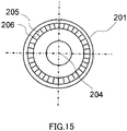
- Fig. 15 shows a schematic plan view of a scale 201 of an encoder.
- a motor control apparatus 200 of the present embodiment includes an optical encoder for sensing the amount of the rotational displacement of a rotary motor 101.
- the encoder includes a scale 201 that has a rotational slit circular disc and a fixed slit circular disc, and a sensor 202 that has a light-emitting element (a light-emitting diode) and a light-receiving element (a photodiode).
- the rotational slit circular disc rotates with the rotation of the rotary motor 101.
- the fixed slit circular disc is fixed.
- the encoder is configured so that the rotational slit circular disc and the fixed slit circular disc are placed between the light-emitting element and the light-receiving element.
- the rotational slit circular disc and the fixed slit circular disc are provided with a lot of slits. Light of the light-emitting element is transmitted or is cut off by the rotation of the rotational slit circular disc. Furthermore, since the fixed slit circular disc converts the output signal of the encoder into a plurality of phases, the fixed slit is divided into a plurality of slits. Therefore, the encoder is provided with a plurality of the light-emitting elements and the light-receiving elements.
- the scale 201 of the encoder is provided with slits of an A-phase pattern 205 and a B-phase pattern 206.
- the scale 201 rotates around a rotation axis 204.
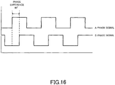
- each of the two light-receiving elements senses the light of the light-emitting element. Therefore, as shown in Fig. 16 , the encoder generates the A-phase signal and the B-phase signal whose phases are 90° different from each other.
- the A-phase signal and the B-phase signal of Fig. 16 are square wave signals that have been formed by waveform shaping of the encoder output of the sine waveform using a waveform shaping circuit.
- a motor controller 203 controls the rotary drive of the rotary motor 101.
- the motor controller 203 compares a motor rotational angle that is a target angle with a motor measured angle that is a measured angle, and performs a feedback control so that the measured angle is equal to the target angle. Therefore, the direction of the mirror 103 can be changed to the angle that corresponds to the target angle.
- the sensing principle is not limited to an optical method, other principles such as a magnetic method can also be employed.
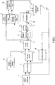
- FIG. 1 is a block diagram of a control which a controller of a motor control apparatus performs.
- the control block in Fig. 1 is a positioning control system in which a rotary encoder is used as an angle sensor for measuring a rotational angle ⁇ m of a motor.
- the figure shows a simple motor model in which a positioning response with respect to a torque command is 1/s 2 , and a positioning control system of a proportional control that performs a position and velocity feedback.
- Reference numeral 1 denotes a target angle command.
- the target angle command 1 commands a target angle of a rotational angle ⁇ m outputted from a motor 17.
- Reference numeral 2 denotes a first adder.
- the first adder 2 feeds back a correction angle 19 outputted from a correction means 18 (a correction unit) to add the target angle by the target angle command 1 and the correction angle 19.
- Reference numeral 3 denotes a second adder.
- the second adder 3 adds an output signal of the first adder 2 and a velocity feedback signal outputted from a differentiator 12.
- Reference numeral 4 denotes a torque command.
- the torque command 4 is calculated by passing the target angle command 1 through the first adder 2 and the second adder 3.
- Reference numeral 5 denotes a third adder.
- the third adder 5 superimposes a sin wave signal (predetermined signal) generated by a signal generating means 13 (a signal generator) on the torque command 4.
- Reference numeral 6 denotes a drive torque.
- the drive torque 6 is outputted from the third adder 5 and is supplied to the motor 17, so that a signal based on the predetermined signal is input, as a component superimposed in the drive torque 6 (drive signal), to the motor 17 (actuator).
- the third adder 5 has a function as a drive means (a drive unit) that supplies the drive torque 6 to the motor 17.
- Reference numeral 17 denotes a motor.
- the motor 17 is provided with integrators 7 and 8, and outputs the rotational angle 9 ( ⁇ m) of the motor 17.
- the motor 17 of the present embodiment includes two integrators 7 and 8 because the motor model in which a position response for the torque command 4 is 1/s2 is applied to the embodiment.
- the rotational angle 9 ( ⁇ m) that is a replacement amount of the motor 17 indicates an actual rotational angle of the motor 17.
- the rotational angle 9 ( ⁇ m) is an actual replacement amount of the motor 17. Thus, it is different from a measured angle that is measured by an encoder.
- Reference numeral 10 denotes an encoder.
- the encoder 10 is a displacement sensing means (a displacement sensor) that senses an actual rotational angle 9 ( ⁇ m) of the motor 17.
- Reference numeral 11 denotes a measured angle ( ⁇ m').
- the measured angle 11 ( ⁇ m') is a displacement amount (angle) measured by the encoder 10 which is a displacement sensing means.
- the encoder 10 senses the actual rotational angle 9 ( ⁇ m) of the motor 17 to calculate the measured angle 11 ( ⁇ m') of the motor 17.
- the sine wave signal outputted from the encoder 10 includes a higher harmonic component. There is also a possibility that the scale of the encoder 10 has process errors.
- the measured angle 11 ( ⁇ m') of the motor 17 measured by the encoder 10 is different from the actual rotational angle 9 ( ⁇ m) of the motor 17. In other words, there is an error between the actual rotational angle 9 ( ⁇ m) and the measured angle 11 ( ⁇ m') of the motor 17 measured by the encoder 10.
- Reference numeral 12 denotes a differentiator.
- the differentiator 12 differentiates a corrected angle 19 ( ⁇ m") corrected by the correction means 18 with respect to time to obtain the rotational velocity of the motor 17.
- the rotational velocity obtained by the differentiator 12 is inputted to the second adder 3 as a velocity feedback signal.
- Reference numeral 13 denotes a signal generating means (a signal generator).
- the signal generating means 13 of the present embodiment generates a sine wave signal (predetermined signal) that has a predetermined amplitude and frequency, and supplies the sine wave signal to the third adder 5 that is a drive means, so that a signal based on the predetermined signal is input to the motor 17.
- the signal generating means 13 of the present embodiment generates a sine wave signal, instead, it can generate another signal such as a Gaussian noise or a triangle wave to supply to the third adder 5.
- Reference numeral 14 denotes a first Fourier transform unit.
- the first Fourier transform unit 14 inputs the drive torque 6 outputted from the third adder 5 to perform a Fourier transform of the drive torque 6.
- the first Fourier transform unit 14 outputs a first amplitude spectrum as a result of performing the Fourier transform of the drive torque 6.
- Reference numeral 15 denotes a second Fourier transform unit.
- the second Fourier transform unit 15 inputs the measured angle 11 ( ⁇ m') of the motor 17 obtained based on the output signal of the encoder 10 to perform a Fourier transform of the measured angle 11 ( ⁇ m').
- the second Fourier transform unit 15 outputs a second amplitude spectrum as a result of performing the Fourier transform of the measured angle 11 ( ⁇ m').
- Reference numeral 16 denotes a correction data generating means (a correction data generator).
- the correction data generating means 16 calculates an amplitude spectrum ratio of a first amplitude spectrum and a second amplitude spectrum.
- the correction data generating means 16 generates correction data W[n] based on the amplitude spectrum ratio. In other words, the correction data generating means 16 generates the correction data based on the drive torque 6 and the measured angle ( ⁇ m') measured by the encoder 10 when a predetermined sine wave signal is supplied to the third adder 5.
- Reference numeral 18 denotes a correction means (a correction unit).
- the correction means 18 corrects the measured angle 11 ( ⁇ m') of the motor 17 measured by the encoder 10 using correction data W[n] generated by the correction data generating means 16.
- the correction means 18 corrects the measured angle 11 ( ⁇ m') by the encoder 10 that is a displacement sensing means (a displacement sensor) so as to be equal to the actual rotational angle 9 ( ⁇ m) of the motor 17. Therefore, the corrected angle 19 corrected by the correction means 18 has a value that is extremely close to the actual rotational angle ( ⁇ m) of the motor 17.
- the corrected angle 19 is fed back to the first adder 2 and the second adder 3.
- the present embodiment uses a rotary encoder as an angle sensor of a rotary motor.
- the encoder has a function as a displacement sensing means of the motor.
- the encoder outputs each of two-phase sine wave signals in 140000 cycles per every rotation of the motor.
- the encoder signals are regarded as including three-order and five-order higher harmonics as expressed by equations 4 and 5.
- Asig 5 sin ⁇ e + ⁇ 2 + 0.05 sin 3 ⁇ e + ⁇ 2 + 0.01 sin 5 ⁇ e + ⁇ 2
- Bsig 5 sin ⁇ e + 0.05 sin 3 ⁇ e + 0.01 sin 5 ⁇ e
- the encoder signal including the higher harmonics is regarded as an ideal sine wave signal, the error that occurs in performing electric split by arc tangent method (tan -1 ).
- the phase angle ⁇ e of the encoder can be regarded as the range of - ⁇ ⁇ ⁇ e ⁇ ⁇
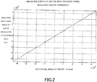
- Fig. 2 shows the relationship between the measured angle ⁇ m' of the motor and the rotational angle ⁇ m of the motor.
- the horizontal axis indicates the rotational angle ⁇ m of the motor and the vertical axis indicates a measured angle ⁇ m' of the motor calculated by the electric split.
- the graph shown in Fig. 2 is linear.
- the graph shown in Fig. 2 is distorted line.
- Fig. 3 shows a relationship between the measured error ⁇ m'- ⁇ m and the rotational angle ⁇ m of the motor.
- the horizontal axis indicates the rotational angle ⁇ m of the motor and the vertical axis indicates the measured error ⁇ m'- ⁇ m between the rotational angle ⁇ m of the motor and the measured angle ⁇ m' of the motor calculated by the electric split.
- the measured error is ideally zero
- the measured error ⁇ m'- ⁇ m of the vertical axis always indicates zero without depending on the rotational angle ⁇ m of the horizontal axis.
- the graph shown in Fig. 3 sinusoidally varies.
- the measured error occurs between the actual rotational angle ⁇ m of the motor and the measured angle ⁇ m' measured by the encoder caused by a higher harmonic component of the encoder output.
- the motor control apparatus of the present embodiment has a correction mode for correcting the measured angle of the encoder and a control mode that performs the actual motor control.
- the motor control apparatus corrects the measured angle in the correction mode before moving to the control mode in which the normal motor control is performed.
- the control system shown in Fig. 1 measures the measured angle ⁇ m' of the motor by the encoder to perform the positioning control of the motor.
- the sine wave frequency is not limited to 100Hz, but another frequency can also be used.
- the control system supplies the drive torque 6 outputted from the third adder 5 to the motor 17 to measure the drive torque 6 and the angle response of the measured angle ⁇ m' (Step S4).
- the drive torque is expressed by Tm[0] and the angle response of the measure angle ⁇ m' of the motor is expressed by ⁇ m'p[0].
- the control system determines whether or not the value of n is smaller than 360 (Step S5). If the value of n is smaller than 360, the control system adds 1 to n (Step S6) and repeats the process of Steps S2 to S4. In other words, when n is 1, 2, ... , 358, 359 (n ⁇ 360), as well as n is 0, the control system calculates the drive torque Tm[n] of the motor and the angle response ⁇ m'p[n] of the measured angle ⁇ m' (Step S4).
- Step S7 the control system performs the Fourier transform of each of the drive torque Tm of the motor and the angle response ⁇ m'p to calculate each of the amplitude spectra (Step S7).
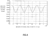
- Fig. 4 shows an amplitude spectrum of the drive torque Tm of the motor.
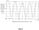
- Fig. 5 shows an amplitude spectrum of the angle response ⁇ m'p.
- Each of the amplitude spectra shown in Figs. 4 and 5 merely represents a term of superimposed frequency 100Hz of the sine wave signal.
- the angle response ⁇ m'p of the measured angle ⁇ m' of the motor 17 is constant with respect to the drive torque Tm.
- the amplitude spectrum of the angle response with respect to the amplitude spectrum of the drive spectrum is constant.
- the correction data W[n] is a weighting data when the measured angle ⁇ m' is ⁇ m'[n] ⁇ m' ⁇ ⁇ m'[n+1], and is calculated so as to satisfy equations 9 and 10 described below.
- K in equation 9 is an arbitrary constant number.
- DFT ( ⁇ m'p) is an amplitude spectrum (the term of 100Hz) calculated by Fourier transform of the angle response ⁇ m'p of the measured angle ⁇ m'.
- DFT (Tm) is an amplitude spectrum (the term of 100Hz) calculated by Fourier transform of the drive torque Tm.
- Fig. 6 shows the relationship between the correction data W and the measured angle ⁇ m'.
- the control system performs the correction using such correction data W to even out the amplitude spectrum ratio of the drive torque Tm and the angle response ⁇ m'p.
- the measurements of the amplitude spectra and the amplitude spectrum ratio can also be performed immediately after the measurements of the drive torque Tm[n] and the angle response ( ⁇ m'p[n]) (Step S4 in Fig. 12 ).
- the corrected angle ⁇ m" to which the measured angle ⁇ m' is corrected is calculated using the correction data W[n] (Step S9).
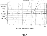
- Fig. 7 shows the corrected measured error ⁇ m"- ⁇ m and the uncorrected measured error ⁇ m'- ⁇ m with respect to the rotational angle ⁇ of the motor.
- the horizontal axis indicates the rotational angle ⁇ m of the motor and the vertical axis indicates the measured error.
- the measured error ⁇ m'- ⁇ m between the rotational angle ⁇ m of the motor and the uncorrected measured angle ⁇ m' is indicated by a dashed line
- the measured error ⁇ m"- ⁇ m between the rotational angle ⁇ m of the motor and the corrected measured angle ⁇ m" is indicated by a solid line.
- the uncorrected measured error ⁇ m'- ⁇ m is large.
- the corrected measured error ⁇ m"- ⁇ m is extremely small.
- the corrected angle ⁇ m" calculated using the correction data W is extremely close to the actual rotational angle ⁇ m of the motor.
- the displacement sensing method of the present embodiment sequentially performs the measurements of the amplitude spectra at a plurality of the measured angles in the range to be corrected among the measured angles ⁇ m' of the motor. Then, the correction of the measured angle ⁇ m' is performed so that the positioning response of each of the measured angles ⁇ m' is constant with respect to the arbitrary drive torque in the range to be corrected.
- the motor control apparatus After the motor control apparatus calculates the corrected angle ⁇ m" in the correction mode, it moves to the control mode in which the motor control apparatus performs a normal motor control.
- the third adder 5 that is a drive means of the motor control apparatus performs a drive control of the motor 17 using the corrected angle ⁇ m" calculated in the correction mode.
- the present embodiment can effectively reduce the measured error with respect to the output signal of the encoder including the higher harmonic signal, using the correction data W to even out the amplitude spectrum ratio. Therefore, the present embodiment can provide a displacement sensing method that reduces the error by the higher harmonic component included in the output signal of the encoder. Furthermore, the present embodiment can provide a motor control apparatus with high accuracy since the motor control apparatus corrects the measured angle of the encoder so that the measured error of the encoder is small.
- a scale pitch of an encoder has a process error.
- the present embodiment uses a rotary encoder as an angle sensor mounted on a rotary motor, which is the same as embodiment 1.
- the encoder of the present embodiment outputs each of two-phase sine wave signals in 140000 cycles per rotation of a motor.
- the scale of the present embodiment is regarded as satisfying equations 15 and 16 with respect to the rotational angle ⁇ m of the motor.
- the encoder of the present embodiment has a process error that satisfies a relation of equations 15 and 16.
- the scale is regarded as having no process error other than the above range.
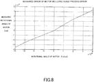
- Fig. 8 shows the relationship between the measured angle ⁇ m' of the motor and the rotational angle ⁇ m of the motor.
- the horizontal axis indicates a rotational angle ⁇ m of the motor and the vertical axis indicates a measured angle ⁇ m' measured by the encoder including a scale process error. If the process error is ideally zero, the graph shown in Fig. 8 is linear. However, since the scale of the present embodiment has a process error that satisfies equations 15 and 16, the graph shown in Fig. 2 is a distorted line.
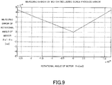
- Fig. 9 shows the relationship between the measured error ⁇ m'- ⁇ m by the encoder that has a process error and the rotational angle ⁇ m of the motor.
- the horizontal axis indicates a rotational angle ⁇ m of the motor
- the vertical axis indicates a measured error ⁇ m'- ⁇ m between the rotational angle ⁇ m of the motor and the measured angle ⁇ m' of the motor measured by the encoder that has a scale process error. If the process error is ideally zero, the measured error ⁇ m'- ⁇ m of the vertical axis always indicates zero without depending on the rotational angle ⁇ m of the vertical axis. However, actually, since there is a process error, it changes as shown in Fig. 9 .
- the correction method is the same as that of embodiment 1. Firstly, the correction method superimposes a sine wave signal of 100Hz on a torque command to a motor in a condition of a positioning control. Then, it applies a drive torque on which the sin wave signal is superimposed to the motor, and measures a drive torque Tm and an angle response ⁇ m'p of the motor. After that, it makes correction data using equations 8 to 10.
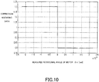
- Fig. 10 shows correction data W made in the present embodiment.
- the vertical axis indicates correction data W and the horizontal axis indicates a measured angle ⁇ m' Since the process error of the scale in the present embodiment satisfies equations 15 and 16, the correction data W shows 1.2 when the measured angle ⁇ m' is smaller than 0. Meanwhile, the correction data W shows 0.8 when the measured angle ⁇ m' is 0 or larger.
- Fig. 11 shows a corrected measured error ⁇ m"- ⁇ m and a uncorrected measured angle ⁇ m'- ⁇ m with respect to a rotational angle ⁇ of the motor.
- the horizontal axis indicates a rotational angle ⁇
- the vertical axis indicates a measured error.
- the measured error ⁇ m'- ⁇ m between the rotational angle ⁇ m and the uncorrected measured angle ⁇ m' is indicated by a dashed line
- the measured error ⁇ m"- ⁇ m between the rotational angle ⁇ m of the motor and the corrected measured angle ⁇ m" is indicated by a solid line.
- the uncorrected measured error ⁇ m'- ⁇ m is large.
- the corrected measured error ⁇ m"- ⁇ m is extremely small.
- the corrected angle ⁇ m" calculated using the correction data W is extremely close to the actual rotational angle ⁇ m.
- the motor control apparatus After the motor control apparatus calculates the corrected angle ⁇ m" in the correction mode, it moves to the control mode in which a normal motor control is performed. In the control mode, the third adder 5 that is a drive means of the motor control apparatus performs a drive control of the motor 17 using the corrected angle ⁇ m" calculated in the correction mode.
- the measured error caused by the scale process error of the encoder can effectively be reduced using the correction data W so that an amplitude spectrum ratio is constant. Therefore, the displacement sensing method that reduces the measured error caused by the scale process error can be provided. Furthermore, a motor control apparatus with high accuracy can be provided by correcting the measured angle of the encoder based on the scale process error.
- a rotational mechanism is used as a movable mechanism, it can also be replaced with a translation mechanism. Therefore, the present invention can be applied to both a rotary encoder and a linear encoder.
- a motor is used as a movable mechanism, it can also be replaced with an actuator such as a piezo actuator.
- an encoder is used as a displacement sensing means, it can also be replaced with a capacitance sensor or PSD (Position Sensitive Detector). If the capacitance sensor or PSD is used, a linearity correction of the displacement sense can be performed.
- a capacitance sensor or PSD Part Sensitive Detector
- a first or more differential value or integration value of the drive force or the displacement amount can be used so that the relationship of the displacement amount with the drive force is constant.
- the displacement correction can be performed by setting an angle or position range including the inhomogeneous part and calculating a correction weighting coefficient.
- the measured accuracy of the encoder is easily improved, and the positioning accuracy can be improved. Therefore, the machine properties can be improved and the quality of a processed object or a workpiece can be improved.
- each of the above embodiments can provide a displacement sensing method that lowers a measured error of an encoder caused by a higher harmonic component included in an output signal of the encoder or a process error of a scale pitch. Furthermore, each of the above embodiments can provide a motor control apparatus with high accuracy by lowering a measured error of the encoder.
- a displacement sensing method of the present invention includes the steps of superimposing a predetermined signal on a torque command to supply a drive torque (6) to a motor (17), measuring an amplitude spectrum ratio between the drive torque (6) in superimposing the predetermined signal on the torque command and a motor angle measured by a displacement sensor (10), generating correction data for evening out the amplitude spectrum ratio, and correcting the measured motor angle so that the motor angle measured by the displacement sensor (10) is equal to an actual motor angle using the correction data.
Landscapes
- Physics & Mathematics (AREA)
- General Physics & Mathematics (AREA)
- Engineering & Computer Science (AREA)
- Technology Law (AREA)
- Power Engineering (AREA)
- Control Of Electric Motors In General (AREA)
- Transmission And Conversion Of Sensor Element Output (AREA)
Description
- The present invention relates to a method of obtaining correction data and a displacement sensing apparatus, more particularly to a method of obtaining correction data that corrects a measured angle and a displacement sensing apparatus that corrects a measured angle to improve measuring accuracy.
- A low output electric motor, which is called a galvano motor, is used for a processing machine such as a laser drilling machine, a laser trimming machine, and a laser repair machine. The galvano motor is required to have an angle sensor with high accuracy. Therefore, an incremental encoder is employed as an angle sensor of the galvano motor.
- An optical rotary encoder and linear encoder are known as an incremental encoder. Such encoders sense displacement information such as a displacement amount and a displacement direction of an object to be sensed by using two signals (sine wave signal and cosine wave signal) which have a phase difference of 90° each other.
- A lot of conventional encoders corrected amplitude of an output signal, an offset, and a phase to improve measuring accuracy.
- For example, Japanese Patent Laid-Open No.
8-145719 10-254549 - However, conventional correction means performed the correction on the premise that the output signal of the encoder is an ideal sine wave signal. However, actually, since the output signal of the encoder includes a higher harmonic component or a nonlinear component, it is not an ideal sine wave. Accordingly, even if the conventional correction means correct the output signal of the encoder, the output signal of the encoder is not ideal sine wave signal.
- A lot of encoders generate a plurality of split pulses including a phase difference corresponding to a split unit from the sine wave signal and the cosine wave signal in order to improve the sensing resolution of the displacement information of the object to be sensed. Such a method is called an electric split. The fact that the output signal of the encoder is not an ideal sine wave signal caused an error in performing the electric split.
- The encoder is processed so that the scale pitches have equal intervals. However, actually, it has a process error.
- Further prior art is disclosed by the following documents:
document DE 10 2004 038621 B3 which comprises a method for obtaining a position signal, documentUS 5 847 475 A which comprises a method of correction between an electrical phase angle and a mechanical output angle of a stepper motor, and documentUS 5 469 215 A which comprises a method and an apparatus for controlling an electric motor with compensation or torque ripple. - The present invention provides a method of obtaining correction data that reduces the measured error caused by the higher harmonic component or the nonlinear component included in the output signal of the encoder and by the process error of the scale pitches, and also provides a displacement sensing apparatus with high accuracy that reduces the measured error.
- The present invention provides a displacement sensing apparatus according to
claim 1, a control apparatus according to claim 11, a processing machine according toclaim 12 and a method of obtaining correction data according toclaim 14. Advantageous further developments are as set out in respective dependent claims. - Other aspects of the present invention will be apparent from the embodiments described below with reference to the drawings.
-
-
Fig. 1 is a control block diagram of a motor control apparatus inembodiment 1. -
Fig. 2 is a diagram showing a relationship between a rotational angle θm of a motor and a measured angle θm' by an encoder inembodiment 1. -
Fig. 3 is a diagram showing a relationship between a rotational angle θm of a motor and a measured error θm'- θm inembodiment 1. -
Fig. 4 is a diagram showing an amplitude spectrum of a drive torque Tm of a motor inembodiment 1. -
Fig. 5 is a diagram showing an amplitude spectrum of an angle response θm'p of a measured angle θm' of a motor inembodiment 1. -
Fig. 6 is a diagram showing correction data inembodiment 1. -
Fig. 7 is a diagram showing an uncorrected measured error θm' - θ and a corrected measured angle θm" - θ inembodiment 1. -
Fig. 8 is a diagram showing a relationship between a rotational angle θm of a motor and a measured angle θm' inembodiment 2. -
Fig. 9 is a diagram showing a relationship between a rotational angle θm of a motor and a measured error θm'- θm inembodiment 2. -
Fig. 10 is a diagram showing correction data inembodiment 2. -
Fig. 11 is a diagram showing an uncorrected measured error θm' - θ and a corrected measured angle θm" - θ inembodiment 2. -
Fig. 12 is a flowchart showing a correction procedure inembodiment 1. -
Fig. 13 is a schematic view showing one example of a laser processing machine. -
Fig. 14 is a schematic view showing one example of a motor control apparatus. -
Fig. 15 is a plan view showing one example of a scale of a rotary encoder. -
Fig. 16 is a diagram showing an A-phase signal and a B-phase signal of encoder outputs. - Exemplary embodiments of the present invention will be described below with reference to the accompanied drawings.
- As one example of a processing machine, the configuration of a laser processing machine will be described.
Fig. 13 shows a schematic view of alaser processing machine 100. Thelaser processing machine 100 is used for various purposes such as cutting of a board, drilling a hole in a board, and welding between metals. - The
laser processing machine 100 of the present embodiment includesrotary motors rotary motors drive mirrors mirrors rotary motors - Thus, changing the directions of the
mirrors rotary motors rotary motors - The laser beam L emitted from a
laser oscillator 105 is irradiated on a laser-processedsurface 106 via themirrors surface 106 that is subject to be processed. - As described above, the
laser processing machine 100 can accurately control the direction of the laser beam L by rotating themirrors surface 106 can be accurately processed. - Next, the configuration of a motor control apparatus that is used for a
laser processing machine 100 will be described.Fig. 14 shows a schematic view of a motor control apparatus.Fig. 15 shows a schematic plan view of ascale 201 of an encoder. - A
motor control apparatus 200 of the present embodiment includes an optical encoder for sensing the amount of the rotational displacement of arotary motor 101. The encoder includes ascale 201 that has a rotational slit circular disc and a fixed slit circular disc, and asensor 202 that has a light-emitting element (a light-emitting diode) and a light-receiving element (a photodiode). The rotational slit circular disc rotates with the rotation of therotary motor 101. On the other hand, the fixed slit circular disc is fixed. The encoder is configured so that the rotational slit circular disc and the fixed slit circular disc are placed between the light-emitting element and the light-receiving element. - The rotational slit circular disc and the fixed slit circular disc are provided with a lot of slits. Light of the light-emitting element is transmitted or is cut off by the rotation of the rotational slit circular disc. Furthermore, since the fixed slit circular disc converts the output signal of the encoder into a plurality of phases, the fixed slit is divided into a plurality of slits. Therefore, the encoder is provided with a plurality of the light-emitting elements and the light-receiving elements.
- As shown in
Fig. 15 , thescale 201 of the encoder is provided with slits of anA-phase pattern 205 and a B-phase pattern 206. Thescale 201 rotates around arotation axis 204. In rotating, when light from the light-emitting element transmits each of the slits of the A-phase pattern and the B-phase pattern, each of the two light-receiving elements senses the light of the light-emitting element. Therefore, as shown inFig. 16 , the encoder generates the A-phase signal and the B-phase signal whose phases are 90° different from each other. The A-phase signal and the B-phase signal ofFig. 16 are square wave signals that have been formed by waveform shaping of the encoder output of the sine waveform using a waveform shaping circuit. - A
motor controller 203 controls the rotary drive of therotary motor 101. Themotor controller 203 compares a motor rotational angle that is a target angle with a motor measured angle that is a measured angle, and performs a feedback control so that the measured angle is equal to the target angle. Therefore, the direction of themirror 103 can be changed to the angle that corresponds to the target angle. - The sensing principle is not limited to an optical method, other principles such as a magnetic method can also be employed.
- Next, a displacement sensing method and a motor control apparatus in
embodiment 1 of the present invention will be described.Fig. 1 is a block diagram of a control which a controller of a motor control apparatus performs. - The control block in
Fig. 1 is a positioning control system in which a rotary encoder is used as an angle sensor for measuring a rotational angle θm of a motor. The figure shows a simple motor model in which a positioning response with respect to a torque command is 1/s2, and a positioning control system of a proportional control that performs a position and velocity feedback. -
Reference numeral 1 denotes a target angle command. Thetarget angle command 1 commands a target angle of a rotational angle θm outputted from amotor 17.Reference numeral 2 denotes a first adder. Thefirst adder 2 feeds back acorrection angle 19 outputted from a correction means 18 (a correction unit) to add the target angle by thetarget angle command 1 and thecorrection angle 19.Reference numeral 3 denotes a second adder. Thesecond adder 3 adds an output signal of thefirst adder 2 and a velocity feedback signal outputted from adifferentiator 12. -
Reference numeral 4 denotes a torque command. Thetorque command 4 is calculated by passing thetarget angle command 1 through thefirst adder 2 and thesecond adder 3.Reference numeral 5 denotes a third adder. Thethird adder 5 superimposes a sin wave signal (predetermined signal) generated by a signal generating means 13 (a signal generator) on thetorque command 4.Reference numeral 6 denotes a drive torque. Thedrive torque 6 is outputted from thethird adder 5 and is supplied to themotor 17, so that a signal based on the predetermined signal is input, as a component superimposed in the drive torque 6 (drive signal), to the motor 17 (actuator). Thus, thethird adder 5 has a function as a drive means (a drive unit) that supplies thedrive torque 6 to themotor 17. -
Reference numeral 17 denotes a motor. Themotor 17 is provided withintegrators motor 17. Themotor 17 of the present embodiment includes twointegrators torque command 4 is 1/s2 is applied to the embodiment. - The rotational angle 9 (θm) that is a replacement amount of the
motor 17 indicates an actual rotational angle of themotor 17. In other words, the rotational angle 9 (θm) is an actual replacement amount of themotor 17. Thus, it is different from a measured angle that is measured by an encoder. -
Reference numeral 10 denotes an encoder. Theencoder 10 is a displacement sensing means (a displacement sensor) that senses an actual rotational angle 9 (θm) of themotor 17. Reference numeral 11 denotes a measured angle (θm'). The measured angle 11 (θm') is a displacement amount (angle) measured by theencoder 10 which is a displacement sensing means. Theencoder 10 senses the actual rotational angle 9 (θm) of themotor 17 to calculate the measured angle 11 (θm') of themotor 17. The sine wave signal outputted from theencoder 10 includes a higher harmonic component. There is also a possibility that the scale of theencoder 10 has process errors. Therefore, strictly speaking, the measured angle 11 (θm') of themotor 17 measured by theencoder 10 is different from the actual rotational angle 9 (θm) of themotor 17. In other words, there is an error between the actual rotational angle 9 (θm) and the measured angle 11 (θm') of themotor 17 measured by theencoder 10. -
Reference numeral 12 denotes a differentiator. Thedifferentiator 12 differentiates a corrected angle 19 (θm") corrected by the correction means 18 with respect to time to obtain the rotational velocity of themotor 17. The rotational velocity obtained by thedifferentiator 12 is inputted to thesecond adder 3 as a velocity feedback signal. -
Reference numeral 13 denotes a signal generating means (a signal generator). The signal generating means 13 of the present embodiment generates a sine wave signal (predetermined signal) that has a predetermined amplitude and frequency, and supplies the sine wave signal to thethird adder 5 that is a drive means, so that a signal based on the predetermined signal is input to themotor 17. Although the signal generating means 13 of the present embodiment generates a sine wave signal, instead, it can generate another signal such as a Gaussian noise or a triangle wave to supply to thethird adder 5. -
Reference numeral 14 denotes a first Fourier transform unit. The firstFourier transform unit 14 inputs thedrive torque 6 outputted from thethird adder 5 to perform a Fourier transform of thedrive torque 6. The firstFourier transform unit 14 outputs a first amplitude spectrum as a result of performing the Fourier transform of thedrive torque 6. -
Reference numeral 15 denotes a second Fourier transform unit. The secondFourier transform unit 15 inputs the measured angle 11 (θm') of themotor 17 obtained based on the output signal of theencoder 10 to perform a Fourier transform of the measured angle 11 (θm'). The secondFourier transform unit 15 outputs a second amplitude spectrum as a result of performing the Fourier transform of the measured angle 11 (θm'). -
Reference numeral 16 denotes a correction data generating means (a correction data generator). The correction data generating means 16 calculates an amplitude spectrum ratio of a first amplitude spectrum and a second amplitude spectrum. The correction data generating means 16 generates correction data W[n] based on the amplitude spectrum ratio. In other words, the correction data generating means 16 generates the correction data based on thedrive torque 6 and the measured angle (θm') measured by theencoder 10 when a predetermined sine wave signal is supplied to thethird adder 5. -
Reference numeral 18 denotes a correction means (a correction unit). The correction means 18 corrects the measured angle 11 (θm') of themotor 17 measured by theencoder 10 using correction data W[n] generated by the correction data generating means 16. The correction means 18 corrects the measured angle 11 (θm') by theencoder 10 that is a displacement sensing means (a displacement sensor) so as to be equal to the actual rotational angle 9 (θm) of themotor 17. Therefore, the correctedangle 19 corrected by the correction means 18 has a value that is extremely close to the actual rotational angle (θm) of themotor 17. The correctedangle 19 is fed back to thefirst adder 2 and thesecond adder 3. - Next, errors of the measured angle that occurs in the control block in
Fig. 1 and a method of correcting the errors will be described in detail. - Firstly, an error that the encoder signal including a higher harmonic component causes with respect to the measured angle (θm') of the motor will be described. The present embodiment uses a rotary encoder as an angle sensor of a rotary motor. The encoder has a function as a displacement sensing means of the motor.
- The encoder outputs each of two-phase sine wave signals in 140000 cycles per every rotation of the motor. When the rotational angle of the motor is θm [rad], a phase angle θe is expressed by
equation 1.
[Equation 1]
- Two-phase signals Asig and Bsig of the encoder that outputs ideal sine waves is expressed by
equations
[Equation 2]
[Equation 3]
- In the embodiment, the encoder signals are regarded as including three-order and five-order higher harmonics as expressed by
equations
[Equation 4]
[Equation 5]
- In the embodiment, the encoder signal including the higher harmonics is regarded as an ideal sine wave signal, the error that occurs in performing electric split by arc tangent method (tan-1). The phase angle θe' of the encoder is calculated by
equation 6 using the encoder signal including higher harmonics.
[Equation 6]
- The measured angle θm' [rad] of the motor is expressed by
equation 7 using the phase signal θe' of the encoder.
[Equation 7]
- Since the encoder is a periodic function, the phase angle θe of the encoder can be regarded as the range of -π ≤ θe ≤ π
-
Fig. 2 shows the relationship between the measured angle θm' of the motor and the rotational angle θm of the motor. InFig. 2 , the horizontal axis indicates the rotational angle θm of the motor and the vertical axis indicates a measured angle θm' of the motor calculated by the electric split. In case that the measured error is ideally zero, the graph shown inFig. 2 is linear. However, since the actual measured angle includes errors, the graph shown inFig. 2 is distorted line. -
Fig. 3 shows a relationship between the measured error θm'-θm and the rotational angle θm of the motor. InFig. 3 , the horizontal axis indicates the rotational angle θm of the motor and the vertical axis indicates the measured error θm'-θm between the rotational angle θm of the motor and the measured angle θm' of the motor calculated by the electric split. In case that the measured error is ideally zero, the measured error θm'-θm of the vertical axis always indicates zero without depending on the rotational angle θm of the horizontal axis. However, since the actual measured angle includes errors, the graph shown inFig. 3 sinusoidally varies. - As described above, the measured error occurs between the actual rotational angle θm of the motor and the measured angle θm' measured by the encoder caused by a higher harmonic component of the encoder output.
- Next, a method of correcting the measured angle θm' that is measured by the encoder will be described with reference to a flowchart of a correction procedure shown in
Fig. 12 . The correction procedure of the present embodiment is performed with the encoder mounted on the motor. - The motor control apparatus of the present embodiment has a correction mode for correcting the measured angle of the encoder and a control mode that performs the actual motor control. The motor control apparatus corrects the measured angle in the correction mode before moving to the control mode in which the normal motor control is performed.
- The control system shown in
Fig. 1 measures the measured angle θm' of the motor by the encoder to perform the positioning control of the motor. In the embodiment, correction coefficients are calculated at 360 points as expressed byequation 8.
[Equation 8]
- Firstly, in
equation 8, the encoder measures the position (angle) satisfying θm'[0]=-n/140000 (n=0) (Step S1). Then, the control system performs the positioning control so that the motor is at this position (Step S2). Next, in the condition of the positioning control, the control system superimposes the sine wave signal of 100Hz that has been generated by the signal generating means 13 on the torque command 4 (Step S3). The sine wave frequency is not limited to 100Hz, but another frequency can also be used. - Based on the result, the control system supplies the
drive torque 6 outputted from thethird adder 5 to themotor 17 to measure thedrive torque 6 and the angle response of the measured angle θm' (Step S4). In this case, the drive torque is expressed by Tm[0] and the angle response of the measure angle θm' of the motor is expressed by θm'p[0]. - The control system determines whether or not the value of n is smaller than 360 (Step S5). If the value of n is smaller than 360, the control system adds 1 to n (Step S6) and repeats the process of Steps S2 to S4. In other words, when n is 1, 2, ... , 358, 359 (n<360), as well as n is 0, the control system calculates the drive torque Tm[n] of the motor and the angle response θm'p[n] of the measured angle θm' (Step S4).
- If the value of n reaches 360, the control system performs the Fourier transform of each of the drive torque Tm of the motor and the angle response θm'p to calculate each of the amplitude spectra (Step S7).
Fig. 4 shows an amplitude spectrum of the drive torque Tm of the motor.Fig. 5 shows an amplitude spectrum of the angle response θm'p. Each of the amplitude spectra shown inFigs. 4 and5 merely represents a term of superimposed frequency 100Hz of the sine wave signal. - If there is no measured error by the encoder, the angle response θm'p of the measured angle θm' of the
motor 17 is constant with respect to the drive torque Tm. In other words, the amplitude spectrum of the angle response with respect to the amplitude spectrum of the drive spectrum (an amplitude spectrum ratio) is constant. - However, actually, a measured error by the encoder occurs. Therefore, as shown in
Figs. 4 and5 , the amplitude spectrum ratio is not constant when the measured angle θm' is used. - Therefore, when the measured error occurs, the control system makes correction data W[n] to even out the amplitude spectrum ratio (Step S8). The correction data W[n] is a weighting data when the measured angle θm' is θm'[n]≤θm'< θm'[n+1], and is calculated so as to satisfy
equations
[Equation 9]
[Equation 10]
- K in
equation 9 is an arbitrary constant number. DFT (θm'p) is an amplitude spectrum (the term of 100Hz) calculated by Fourier transform of the angle response θm'p of the measured angle θm'. DFT (Tm) is an amplitude spectrum (the term of 100Hz) calculated by Fourier transform of the drive torque Tm.Fig. 6 shows the relationship between the correction data W and the measured angle θm'. The control system performs the correction using such correction data W to even out the amplitude spectrum ratio of the drive torque Tm and the angle response θm'p. The measurements of the amplitude spectra and the amplitude spectrum ratio can also be performed immediately after the measurements of the drive torque Tm[n] and the angle response (θm'p[n]) (Step S4 inFig. 12 ). - The corrected angle θm" to which the measured angle θm' is corrected is calculated using the correction data W[n] (Step S9). When the measured angle θm' satisfies (2n/360) × (n-180)/140000 ≤ θm' < (2n/360) × (n-180)/140000, the corrected angle θm" is expressed by equation 11.
[Equation 11]
-
Fig. 7 shows the corrected measured error θm"-θm and the uncorrected measured error θm'-θm with respect to the rotational angle θ of the motor. InFig. 7 , the horizontal axis indicates the rotational angle θm of the motor and the vertical axis indicates the measured error. The measured error θm'-θm between the rotational angle θm of the motor and the uncorrected measured angle θm' is indicated by a dashed line, and the measured error θm"-θm between the rotational angle θm of the motor and the corrected measured angle θm" is indicated by a solid line. - As shown in
Fig. 7 , the uncorrected measured error θm'-θm is large. However, the corrected measured error θm"-θm is extremely small. In other words, the corrected angle θm" calculated using the correction data W is extremely close to the actual rotational angle θm of the motor. - As described above, the displacement sensing method of the present embodiment sequentially performs the measurements of the amplitude spectra at a plurality of the measured angles in the range to be corrected among the measured angles θm' of the motor. Then, the correction of the measured angle θm' is performed so that the positioning response of each of the measured angles θm' is constant with respect to the arbitrary drive torque in the range to be corrected.
- After the motor control apparatus calculates the corrected angle θm" in the correction mode, it moves to the control mode in which the motor control apparatus performs a normal motor control. In the control mode, the
third adder 5 that is a drive means of the motor control apparatus performs a drive control of themotor 17 using the corrected angle θm" calculated in the correction mode. - As described above, the present embodiment can effectively reduce the measured error with respect to the output signal of the encoder including the higher harmonic signal, using the correction data W to even out the amplitude spectrum ratio. Therefore, the present embodiment can provide a displacement sensing method that reduces the error by the higher harmonic component included in the output signal of the encoder. Furthermore, the present embodiment can provide a motor control apparatus with high accuracy since the motor control apparatus corrects the measured angle of the encoder so that the measured error of the encoder is small.
- In the present embodiment, a scale pitch of an encoder has a process error. The present embodiment uses a rotary encoder as an angle sensor mounted on a rotary motor, which is the same as
embodiment 1. - As in the case of
embodiment 1, the encoder of the present embodiment outputs each of two-phase sine wave signals in 140000 cycles per rotation of a motor. When the actual rotational angle of the motor is θm[rad], the phase angle θe is expressed byequation 12, which is the same asequation 1.
[Equation 12]
- Furthermore, two-phase sine wave signals Asig and Bsig of the encoder are expressed by
equations equations
[Equation 13]
[Equation 14]
- However, if the scale pitch has a process error, the relation of
equation 1 is not satisfied and the accurate position can not be measured. In the present embodiment, the correction procedure that corrects the measured angle θm of the motor in case that the scale pitch has the process error as described above will be described. - Firstly, the error that the output signal of the encoder having a process error in the scale pitch provides the measured angle of the motor will be described.
- The scale of the present embodiment is regarded as
satisfying equations equation 15.
[Equation 15]
- When the range of the rotational angle of the motor is 0 ≤ θm < (-π/140000)×0.8, the phase angle θe' of the encoder is expressed by
equation 16.
[Equation 16]
- In this case, the encoder of the present embodiment has a process error that satisfies a relation of
equations equation 17.
[Equation 17]
-
Fig. 8 shows the relationship between the measured angle θm' of the motor and the rotational angle θm of the motor. InFig. 8 , the horizontal axis indicates a rotational angle θm of the motor and the vertical axis indicates a measured angle θm' measured by the encoder including a scale process error. If the process error is ideally zero, the graph shown inFig. 8 is linear. However, since the scale of the present embodiment has a process error that satisfiesequations Fig. 2 is a distorted line. -
Fig. 9 shows the relationship between the measured error θm'-θm by the encoder that has a process error and the rotational angle θm of the motor. InFig. 9 , the horizontal axis indicates a rotational angle θm of the motor, and the vertical axis indicates a measured error θm'-θm between the rotational angle θm of the motor and the measured angle θm' of the motor measured by the encoder that has a scale process error. If the process error is ideally zero, the measured error θm'-θm of the vertical axis always indicates zero without depending on the rotational angle θm of the vertical axis. However, actually, since there is a process error, it changes as shown inFig. 9 . - Next, a correction method of a measured error θm'-θm that is caused by a process error of the scale will be described. The correction method is the same as that of
embodiment 1. Firstly, the correction method superimposes a sine wave signal of 100Hz on a torque command to a motor in a condition of a positioning control. Then, it applies a drive torque on which the sin wave signal is superimposed to the motor, and measures a drive torque Tm and an angle response θm'p of the motor. After that, it makes correctiondata using equations 8 to 10. -
Fig. 10 shows correction data W made in the present embodiment. The vertical axis indicates correction data W and the horizontal axis indicates a measured angle θm' Since the process error of the scale in the present embodiment satisfiesequations - Next, a correction angle θm" to which a measured angle θm" is corrected using the correction data W will be described.
-
Fig. 11 shows a corrected measured error θm"-θm and a uncorrected measured angle θm'-θm with respect to a rotational angle θ of the motor. InFig. 11 , the horizontal axis indicates a rotational angle θ, and the vertical axis indicates a measured error. The measured error θm'-θm between the rotational angle θm and the uncorrected measured angle θm' is indicated by a dashed line, and the measured error θm"-θm between the rotational angle θm of the motor and the corrected measured angle θm" is indicated by a solid line. - As shown in
Fig. 11 , the uncorrected measured error θm'-θm is large. However, the corrected measured error θm"-θm is extremely small. In other words, the corrected angle θm" calculated using the correction data W is extremely close to the actual rotational angle θm. - After the motor control apparatus calculates the corrected angle θm" in the correction mode, it moves to the control mode in which a normal motor control is performed. In the control mode, the
third adder 5 that is a drive means of the motor control apparatus performs a drive control of themotor 17 using the corrected angle θm" calculated in the correction mode. - As described above, according to the present embodiment, the measured error caused by the scale process error of the encoder can effectively be reduced using the correction data W so that an amplitude spectrum ratio is constant. Therefore, the displacement sensing method that reduces the measured error caused by the scale process error can be provided. Furthermore, a motor control apparatus with high accuracy can be provided by correcting the measured angle of the encoder based on the scale process error.
- As described above, the present invention was specifically described based on the embodiments. However, the present invention is not limited to these embodiments and various variations and modifications may be made without departing from the scope of the present invention.
- For example, in
embodiments - Although an encoder is used as a displacement sensing means, it can also be replaced with a capacitance sensor or PSD (Position Sensitive Detector). If the capacitance sensor or PSD is used, a linearity correction of the displacement sense can be performed.
- A first or more differential value or integration value of the drive force or the displacement amount can be used so that the relationship of the displacement amount with the drive force is constant.
- In
embodiment 2, even if the scale pitch of the encoder is inhomogeneous, the displacement correction can be performed by setting an angle or position range including the inhomogeneous part and calculating a correction weighting coefficient. - According to the positioning apparatus of the galvano motor using the correction method of the above embodiments, or the laser processing machine or the processing machine using the same, the measured accuracy of the encoder is easily improved, and the positioning accuracy can be improved. Therefore, the machine properties can be improved and the quality of a processed object or a workpiece can be improved.
- As described above, each of the above embodiments can provide a displacement sensing method that lowers a measured error of an encoder caused by a higher harmonic component included in an output signal of the encoder or a process error of a scale pitch. Furthermore, each of the above embodiments can provide a motor control apparatus with high accuracy by lowering a measured error of the encoder.
- A displacement sensing method of the present invention includes the steps of superimposing a predetermined signal on a torque command to supply a drive torque (6) to a motor (17), measuring an amplitude spectrum ratio between the drive torque (6) in superimposing the predetermined signal on the torque command and a motor angle measured by a displacement sensor (10), generating correction data for evening out the amplitude spectrum ratio, and correcting the measured motor angle so that the motor angle measured by the displacement sensor (10) is equal to an actual motor angle using the correction data.
Claims (14)
- A displacement sensing apparatus for sensing displacement by an actuator (17), the apparatus comprising:a sensor (10) configured to sense displacement by the actuator (17), the actuator (17) being controlled in a control system based on a target displacement and an output signal (11) of the sensor (10);a signal generator (13) configured to generate a predetermined signal to be supplied to the control system including a drive unit (5) configured to drive the actuator (17) using a drive signal (6), so that a signal based on the predetermined signal is input to the actuator (17); anda correction data generator (16) configured to generate correction data, for compensation for an error in an output signal of the sensor, based on the drive signal (6) obtained with the predetermined signal being supplied to the control system and on displacement by the actuator (17) sensed by the sensor (10) with the predetermined signal being supplied to the control system with respect to each of a plurality of the target displacement.
- The apparatus according to claim 1, wherein the correction data generator (16) is configured to generate the correction data based on the sensed displacement of the actuator (17) with the actuator (17) being controlled in the control system based on each of the plurality of the target displacement and with the predetermined signal being supplied to the control system.
- The apparatus according to claim 1, wherein the correction data generator (16) is configured to generate the correction data based on a ratio between an amplitude of the sensed displacement and an amplitude of a drive signal supplied by the drive unit (5) to the actuator (17) with respect to each of the plurality of the target displacement.
- The apparatus according to claim 3, wherein the correction data generator (16) is configured to generate the correction data such that the correction data even out a plurality of the ratios over the plurality of the target displacement.
- The apparatus according to claim 1, further comprising a correction unit (18) configured to correct an output signal of the sensor (10) based on the correction data.
- The apparatus according to claim 1, wherein the signal generator (13) is configured to generate, as the predetermined signal, a sine wave signal.
- The apparatus according to claim 3, wherein the correction data generator (16) is configured to obtain the amplitude of the sensed displacement and the amplitude of the drive signal by Fourier transform of the sensed displacement and the drive signal, respectively.
- The apparatus according to claim 7, wherein the correction data generator (16) is configured to obtain, as the amplitude of the sensed displacement, an amplitude spectrum of the sensed displacement with respect to a predetermined frequency, and to obtain, as the amplitude of the drive signal, an amplitude spectrum of the drive signal with respect to the predetermined frequency.
- The apparatus according to claim 1, wherein the sensor (10) is an encoder.
- The apparatus according to claim 1, wherein the actuator (17) is a motor.
- A control apparatus (200) including an actuator (17) and controlling displacement by the actuator (17), the apparatus comprising:the displacement sensing apparatus, according to any of preceding claims, for sensing the displacement.
- A processing machine (100) comprising the control apparatus (200) according to claim 11.
- The processing machine (100) according to claim 12, further comprising a mirror (103, 104) to be driven by the actuator, a material being irradiated with a beam via the mirror (103, 104).
- A method of obtaining correction data for compensation for an error of an output signal of a sensor (10) for sensing displacement by an actuator (17), the actuator (17) being driven by a drive unit (5) using a drive signal (6), in a control system which controls the actuator based on a target displacement and an output signal of the sensor (10), the method comprising:supplying a predetermined signal to the control system with respect to each of a plurality of the target displacement, so that a signal based on the predetermined signal is input to the actuator (17); andgenerating the correction data based on the drive signal (6) obtained with the predetermined signal being supplied to the control system and on displacement by the actuator (17) sensed by the sensor (10) with the predetermined signal being supplied to the control system with respect to each of the plurality of the target displacement.
Applications Claiming Priority (1)
| Application Number | Priority Date | Filing Date | Title |
|---|---|---|---|
| JP2007238695A JP5111031B2 (en) | 2007-09-14 | 2007-09-14 | Displacement detection method and motor control device |
Publications (3)
| Publication Number | Publication Date |
|---|---|
| EP2037220A2 EP2037220A2 (en) | 2009-03-18 |
| EP2037220A3 EP2037220A3 (en) | 2014-01-01 |
| EP2037220B1 true EP2037220B1 (en) | 2017-11-15 |
Family
ID=39791200
Family Applications (1)
| Application Number | Title | Priority Date | Filing Date |
|---|---|---|---|
| EP08163470.1A Active EP2037220B1 (en) | 2007-09-14 | 2008-09-02 | Displacement sensing method and motor control apparatus |
Country Status (6)
| Country | Link |
|---|---|
| US (2) | US8072176B2 (en) |
| EP (1) | EP2037220B1 (en) |
| JP (1) | JP5111031B2 (en) |
| KR (1) | KR101079488B1 (en) |
| CN (1) | CN101387504B (en) |
| TW (1) | TWI359557B (en) |
Families Citing this family (21)
| Publication number | Priority date | Publication date | Assignee | Title |
|---|---|---|---|---|
| WO2012009198A2 (en) | 2010-07-14 | 2012-01-19 | University Of Florida Research Foundation, Inc. | System and method for assessing the performance of an attitude control system for small satellites |
| CN102332856B (en) * | 2010-07-14 | 2014-04-02 | 台达电子工业股份有限公司 | Dynamic compensating device for feedback position of encoder and dynamic compensating method thereof |
| KR101222465B1 (en) * | 2010-09-29 | 2013-01-15 | 국방과학연구소 | Method and apparatus for adjusting zero point of guided weapon control plates |
| TWI451067B (en) * | 2011-12-19 | 2014-09-01 | Au Optronics Corp | Optical encoder |
| US9261872B2 (en) * | 2012-01-19 | 2016-02-16 | Mitsubishi Electric Research Laboratories, Inc. | System and method for controlling redundant actuators of a machine |
| KR101361551B1 (en) * | 2012-05-16 | 2014-02-24 | (주)아이파워컨 | device and method for correcting phase error of resolver |
| JP5995589B2 (en) * | 2012-07-30 | 2016-09-21 | キヤノン株式会社 | Correction value deriving device, displacement amount deriving device, control device, and correction value deriving method |
| JP2014124000A (en) * | 2012-12-20 | 2014-07-03 | Canon Inc | Control device for actuator |
| JP6595755B2 (en) * | 2014-12-02 | 2019-10-23 | 日本電産サンキョー株式会社 | Correction table creation device, encoder, and correction table creation method |
| CN107532930B (en) * | 2015-04-29 | 2021-07-30 | 瑞尼斯豪公司 | Method for determining subdivision errors |
| JP6193938B2 (en) * | 2015-08-31 | 2017-09-06 | ファナック株式会社 | Rotation angle detector with function to detect foreign material intrusion from frequency characteristics of signal |
| CN105643388B (en) * | 2016-02-02 | 2018-02-06 | 上海日进机床有限公司 | Workpiece size detecting device, method and Multistation formula crystal bar process equipment |
| US10312837B2 (en) * | 2016-05-02 | 2019-06-04 | Canon Kabushiki Kaisha | Information processing apparatus, and recording medium storing computer program |
| CN107547014A (en) * | 2016-06-23 | 2018-01-05 | 上海北京大学微电子研究院 | Brshless DC motor hardware system based on isolation technology |
| KR101859206B1 (en) | 2017-07-20 | 2018-06-28 | 주식회사 제미스코 | A device of edge press |
| US10895866B1 (en) * | 2018-03-08 | 2021-01-19 | Apple Inc. | Position error correction for electric motors |
| CN112805536A (en) * | 2018-09-24 | 2021-05-14 | 株式会社尼康 | Encoder, drive device, robot device, control system, and control method thereof |
| JP7161439B2 (en) * | 2019-04-23 | 2022-10-26 | ルネサスエレクトロニクス株式会社 | Semiconductor device and motor control system |
| CN110961798B (en) * | 2019-12-02 | 2021-01-12 | 固高伺创驱动技术(深圳)有限公司 | Laser cutting control system and control method |
| CN111106764B (en) * | 2019-12-06 | 2021-07-02 | 清能德创电气技术(北京)有限公司 | Sine and cosine encoder correction method and system |
| CN114093280B (en) * | 2021-11-22 | 2024-01-09 | 马努(上海)艺术设计有限公司 | Angle correction method, angle limiter, display unit and display system |
Citations (1)
| Publication number | Priority date | Publication date | Assignee | Title |
|---|---|---|---|---|
| EP0306922A2 (en) * | 1987-09-08 | 1989-03-15 | Kabushiki Kaisha Meidensha | Control system for controlling revolution speed of electric motor |
Family Cites Families (26)
| Publication number | Priority date | Publication date | Assignee | Title |
|---|---|---|---|---|
| US4160200A (en) * | 1976-06-29 | 1979-07-03 | Ricoh Company, Ltd. | Servo control apparatus |
| GB2088086B (en) * | 1980-11-19 | 1984-05-10 | Marconi Co Ltd | Apparatus for accurately moving a body in accordance with a predetermined motion |
| JPS5846413A (en) * | 1981-09-14 | 1983-03-17 | Hitachi Ltd | Electric servomechanism |
| GB8136055D0 (en) * | 1981-11-30 | 2003-04-09 | Marconi Co Ltd | Radar tracking system |
| JPS61132064A (en) * | 1984-11-29 | 1986-06-19 | Sony Corp | Brushless motor |
| JPS628585A (en) | 1985-07-05 | 1987-01-16 | Mitsubishi Electric Corp | Laser light source apparatus |
| JPH01148100A (en) | 1987-12-01 | 1989-06-09 | Matsushita Electric Ind Co Ltd | Position controller |
| EP0401383A4 (en) * | 1988-12-23 | 1992-04-01 | Fanuc Ltd | Methods of detecting oscillation in the servo system and automatically adjusting the speed loop gain |
| JP3242223B2 (en) * | 1993-08-02 | 2001-12-25 | オークマ株式会社 | Motor control device |
| EP0739501B1 (en) | 1994-01-11 | 1998-10-28 | Robert Bosch Gmbh | Correction process between the electric phase angle and mechanical output angle of a step motor |
| JPH08145719A (en) | 1994-09-22 | 1996-06-07 | Canon Inc | Method for detecting position or angle |
| JP3281561B2 (en) * | 1996-12-25 | 2002-05-13 | シャープ株式会社 | Motor speed control device |
| JPH10254549A (en) | 1997-03-06 | 1998-09-25 | Canon Inc | Positioning controller |
| US6081087A (en) * | 1997-10-27 | 2000-06-27 | Matsushita Electric Industrial Co., Ltd. | Motor control apparatus |
| US6694816B2 (en) * | 2000-12-06 | 2004-02-24 | Nsk Ltd. | Apparatus and method for evaluating rotational accuracy of rolling bearing and rolling bearing evaluated by the rotational accuracy evaluation method, and apparatus and method for radial vibration of rotating body and rotation unit with rotating body evaluated by the radial vibration evaluation method |
| JP3867009B2 (en) * | 2002-04-24 | 2007-01-10 | 三菱電機株式会社 | Frequency characteristic identification method and drive control apparatus |
| JP2004272370A (en) * | 2003-03-05 | 2004-09-30 | Toshiba Corp | Control device and data access method |
| JP2006042537A (en) | 2004-07-29 | 2006-02-09 | Japan Servo Co Ltd | Brushless dc motor added with magnetic encoder and signal processing circuit |
| DE102004038621B3 (en) | 2004-08-09 | 2006-02-16 | Siemens Ag | Determination procedure for a position signal |
| JP2006141141A (en) * | 2004-11-12 | 2006-06-01 | Konica Minolta Medical & Graphic Inc | Transport device, image scanner, and image forming apparatus |
| JP2006170946A (en) * | 2004-12-20 | 2006-06-29 | Yaskawa Electric Corp | Rotary table controller |
| US7633256B2 (en) * | 2005-05-04 | 2009-12-15 | Lexmark International, Inc. | Encoder eccentricity correction for motion control systems |
| JP2007043818A (en) | 2005-08-03 | 2007-02-15 | Hitachi Ltd | Unit and method for motor control |
| JP2007107886A (en) * | 2005-10-11 | 2007-04-26 | Yaskawa Electric Corp | Error compensation device for encoder and the encoder |
| JP4708992B2 (en) * | 2005-12-12 | 2011-06-22 | 日立オートモティブシステムズ株式会社 | Position detecting apparatus and synchronous motor driving apparatus using the same |
| JP4568298B2 (en) * | 2007-03-16 | 2010-10-27 | オークマ株式会社 | Position detection device |
-
2007
- 2007-09-14 JP JP2007238695A patent/JP5111031B2/en active Active
-
2008
- 2008-09-02 EP EP08163470.1A patent/EP2037220B1/en active Active
- 2008-09-09 US US12/206,797 patent/US8072176B2/en not_active Ceased
- 2008-09-12 CN CN200810149119XA patent/CN101387504B/en active Active
- 2008-09-12 TW TW097135148A patent/TWI359557B/en active
- 2008-09-12 KR KR1020080090515A patent/KR101079488B1/en active IP Right Grant
-
2013
- 2013-12-05 US US14/098,442 patent/USRE46899E1/en active Active
Patent Citations (1)
| Publication number | Priority date | Publication date | Assignee | Title |
|---|---|---|---|---|
| EP0306922A2 (en) * | 1987-09-08 | 1989-03-15 | Kabushiki Kaisha Meidensha | Control system for controlling revolution speed of electric motor |
Also Published As
| Publication number | Publication date |
|---|---|
| CN101387504B (en) | 2011-05-25 |
| JP5111031B2 (en) | 2012-12-26 |
| US8072176B2 (en) | 2011-12-06 |
| TWI359557B (en) | 2012-03-01 |
| USRE46899E1 (en) | 2018-06-19 |
| US20090072774A1 (en) | 2009-03-19 |
| KR101079488B1 (en) | 2011-11-03 |
| EP2037220A3 (en) | 2014-01-01 |
| JP2009069031A (en) | 2009-04-02 |
| CN101387504A (en) | 2009-03-18 |
| KR20090028479A (en) | 2009-03-18 |
| EP2037220A2 (en) | 2009-03-18 |
| TW200934093A (en) | 2009-08-01 |
Similar Documents
| Publication | Publication Date | Title |
|---|---|---|
| EP2037220B1 (en) | Displacement sensing method and motor control apparatus | |
| EP2133169A2 (en) | Displacement detecting method, correction table making method, motor control apparatus, and processing machine | |
| EP1978328B1 (en) | Oscillating scanning probe with constant contact force | |
| CN109827505B (en) | High-precision laser scanning galvanometer position sensor calibration system | |
| CN110160436B (en) | Error measuring method and device of linear displacement sensor | |
| JP4014719B2 (en) | NC machine tool control apparatus and positioning control method | |
| US8510069B2 (en) | Feedback apparatus and feedback method for controlling a servomotor | |
| EP2669701B1 (en) | Calibration to improve weather radar positioning determination | |
| US11624812B2 (en) | Method of characterizing, calibrating, and controlling galvanometer laser steering systems | |
| US9046384B2 (en) | Self-calibration method for angle detector, angle detector, circumferential scale calibration device, and angle detector calibration device | |
| US9557730B2 (en) | Driving apparatus and article processing apparatus | |
| JP5383887B2 (en) | Displacement detection device, control device, machine tool device, irradiation device, and displacement detection method | |
| JP2007327770A (en) | Output signal correcting device and output signal correcting method of digital scale | |
| US20040212862A1 (en) | Optical scanner and laser machining apparatus | |
| JP4223324B2 (en) | Optical encoder | |
| JP4580600B2 (en) | Galvano scanner control method, apparatus, and galvano scanner | |
| EP2112464A1 (en) | Tracking type laser interferometer | |
| JP2005308547A (en) | Encoder, its signal confirmation device, and signal confirmation program | |
| Gilyazov et al. | Angle Sensor for a High-Speed Galvo Scanner | |
| JP2021047033A (en) | Encoder and encoder control method | |
| JP2012246906A (en) | Rotational angle measuring method, rotational angle measuring device, engine valve control method and engine valve control device | |
| JPS63253209A (en) | Shape measuring instrument |
Legal Events
| Date | Code | Title | Description |
|---|---|---|---|
| PUAI | Public reference made under article 153(3) epc to a published international application that has entered the european phase |
Free format text: ORIGINAL CODE: 0009012 |
|
| AK | Designated contracting states |
Kind code of ref document: A2 Designated state(s): AT BE BG CH CY CZ DE DK EE ES FI FR GB GR HR HU IE IS IT LI LT LU LV MC MT NL NO PL PT RO SE SI SK TR |
|
| AX | Request for extension of the european patent |
Extension state: AL BA MK RS |
|
| PUAL | Search report despatched |
Free format text: ORIGINAL CODE: 0009013 |
|
| AK | Designated contracting states |
Kind code of ref document: A3 Designated state(s): AT BE BG CH CY CZ DE DK EE ES FI FR GB GR HR HU IE IS IT LI LT LU LV MC MT NL NO PL PT RO SE SI SK TR |
|
| AX | Request for extension of the european patent |
Extension state: AL BA MK RS |
|
| RIC1 | Information provided on ipc code assigned before grant |
Ipc: G01D 3/02 20060101AFI20131122BHEP |
|
| 17P | Request for examination filed |
Effective date: 20140318 |
|
| RBV | Designated contracting states (corrected) |
Designated state(s): AT BE BG CH CY CZ DE DK EE ES FI FR GB GR HR HU IE IS IT LI LT LU LV MC MT NL NO PL PT RO SE SI SK TR |
|
| 17Q | First examination report despatched |
Effective date: 20140730 |
|
| AKX | Designation fees paid |
Designated state(s): DE |
|
| GRAP | Despatch of communication of intention to grant a patent |
Free format text: ORIGINAL CODE: EPIDOSNIGR1 |
|
| INTG | Intention to grant announced |
Effective date: 20161026 |
|
| RIN1 | Information on inventor provided before grant (corrected) |
Inventor name: UEDA, SHINJI |
|
| GRAJ | Information related to disapproval of communication of intention to grant by the applicant or resumption of examination proceedings by the epo deleted |
Free format text: ORIGINAL CODE: EPIDOSDIGR1 |
|
| GRAP | Despatch of communication of intention to grant a patent |
Free format text: ORIGINAL CODE: EPIDOSNIGR1 |
|
| INTC | Intention to grant announced (deleted) | ||
| INTG | Intention to grant announced |
Effective date: 20170328 |
|
| GRAS | Grant fee paid |
Free format text: ORIGINAL CODE: EPIDOSNIGR3 |
|
| GRAA | (expected) grant |
Free format text: ORIGINAL CODE: 0009210 |
|
| AK | Designated contracting states |
Kind code of ref document: B1 Designated state(s): DE |
|
| REG | Reference to a national code |
Ref country code: DE Ref legal event code: R096 Ref document number: 602008052947 Country of ref document: DE |
|
| REG | Reference to a national code |
Ref country code: DE Ref legal event code: R097 Ref document number: 602008052947 Country of ref document: DE |
|
| PLBE | No opposition filed within time limit |
Free format text: ORIGINAL CODE: 0009261 |
|
| STAA | Information on the status of an ep patent application or granted ep patent |
Free format text: STATUS: NO OPPOSITION FILED WITHIN TIME LIMIT |
|
| 26N | No opposition filed |
Effective date: 20180817 |
|
| PGFP | Annual fee paid to national office [announced via postgrant information from national office to epo] |
Ref country code: DE Payment date: 20230822 Year of fee payment: 16 |