EP2037166A2 - Machine covering with a protective covering adjustable in length - Google Patents
Machine covering with a protective covering adjustable in length Download PDFInfo
- Publication number
- EP2037166A2 EP2037166A2 EP08015810A EP08015810A EP2037166A2 EP 2037166 A2 EP2037166 A2 EP 2037166A2 EP 08015810 A EP08015810 A EP 08015810A EP 08015810 A EP08015810 A EP 08015810A EP 2037166 A2 EP2037166 A2 EP 2037166A2
- Authority
- EP
- European Patent Office
- Prior art keywords
- movable
- coupling member
- terminal member
- stationary
- machine
- Prior art date
- Legal status (The legal status is an assumption and is not a legal conclusion. Google has not performed a legal analysis and makes no representation as to the accuracy of the status listed.)
- Withdrawn
Links
Images


Classifications
-
- F—MECHANICAL ENGINEERING; LIGHTING; HEATING; WEAPONS; BLASTING
- F16—ENGINEERING ELEMENTS AND UNITS; GENERAL MEASURES FOR PRODUCING AND MAINTAINING EFFECTIVE FUNCTIONING OF MACHINES OR INSTALLATIONS; THERMAL INSULATION IN GENERAL
- F16P—SAFETY DEVICES IN GENERAL; SAFETY DEVICES FOR PRESSES
- F16P3/00—Safety devices acting in conjunction with the control or operation of a machine; Control arrangements requiring the simultaneous use of two or more parts of the body
- F16P3/02—Screens or other safety members moving in synchronism with members which move to and fro
Definitions
- Such machine covers are often designed as if necessary from above accessible roofing. In the normal operating state, these close the working space upwards. For example, from above for crane loading of large and heavy workpieces, it is necessary to form the protective or roof covers releasably and displaceably. In this context, it is known, for example, to release appropriate screw connections or bolt locks by hand to open and then to move the protective cover opening by hand, and then to undo these operations to close again.
- These processes are partly also by a controlled opening and closing by electrical, pneumatic or hydraulic.
- consoles end frames with their own drive. All of these solutions are complicated and expensive. They either require expensive electrical, pneumatic or hydraulic additional parts, special manufacturer-specific interfaces or manual intervention.
- the present invention has for its object to provide a machine cover of the type mentioned in such a way that it can be easily and quickly opened and closed again in a simple mechanical way without manual intervention with cost-effective means purely mechanical way.
- the invention proposes that the end of the protective cover stationary in the working area is firmly connected to a double-sided reversible coupling member which has a releasable mechanical connection to the stationary connecting member in the working area of the protective cover.
- Such a machine cover is simple, reliable and inexpensive, requires no manual intervention for unlocking and locking and works with integrated parts purely mechanically without external drives. It uses the available on each machine in each machine axis and machine side controllable overstroke, in which the variable-length protective cover beyond their normal work area going further can be shortened a little further into a normally unused Kochhub Symposium. There, the corresponding unlocking and locking operations between the coupling member and the stationary terminal member and the movable terminal member carried by simple mechanical movement pressure operations.
- the mechanical pressure cans in the overstroke range simultaneously or according to claim 5 respond successively.
- the pressure cell for the releasable mechanical connection of the coupling member to the movable terminal member respond to those for the releasable mechanical connection of the coupling member with the stationary terminal member.
- the further embodiment according to claim 8 is in the overstroke - ie outside the normal working area - ensure an accurate motion control of the movable connecting member relative to the coupling member and a stop-related entrainment of the coupling member.
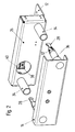
- Fig. 1 is a variable-length protective cover 10 of any kind - such as a bellows, a roll cover with steel or plastic tape, a slat cover, a link skirt, a telescopic steel cover o. The like.
- a variable-length protective cover 10 of any kind - such as a bellows, a roll cover with steel or plastic tape, a slat cover, a link skirt, a telescopic steel cover o. The like.
- - At one end with a movable terminal member 14 and at the other end with a coupling member 26 fixedly connected ,
- the movable connecting member 14 on the machine side linear reciprocating driven, while the coupling member 26 is releasably connected in this work area 16 with a machine-connected stationary terminal member 12.
- the protective cover 10 can be shortened in accordance with an abbreviated shortening in its operative working area 16 and pulled apart in a prolonged manner.
- the terminal member 14 can move with its parts connected between a minimum operating position 18 with the strongest shortening of the protective cover 10 and a maximum operating position 20 with the greatest possible extension of the protective cover 10.
- the operating minimum position 18 is adjoined by an overstroke region 22 with a maximum overstroke position 24.
- the Studentshub Society 22 is outside the normal operating or working state, if necessary, the machine side controlled to the Protective cover 10, for example, from above for crane loading of large and heavy workpieces according to Fig. 6 to open and later again according to Fig. 1 close.
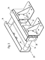
- the coupling member 26 When opening operation, the coupling member 26 is mechanically separated at length shortened Schutzabdekkung 10 from the stationary terminal member 12 and mechanically connected to the movable terminal member 14. In this opening state, the movable terminal member 14, the coupling member 26 with the shortened protective cover 10 retreat, so that between the coupling member 26 and the stationary terminal member 12 according to Fig. 6 a space for corresponding crane loads o. The like. arises. Conversely, in the subsequent closing operation, the coupling member 26 from the movable terminal member 14 - the free space closes - moves to the stationary terminal member 12 and thereby mechanically separated from the movable terminal member 14 and mechanically connected to the stationary terminal member 12. As a result, the normal operating or working state is restored.
- the movable connecting member 14 with at least one movement stop 36 in the overstroke 22 is retractable. Upon reaching or within the same, the movement stop 36 abuts against the end face of a guide sleeve 34 on the coupling member 26. Previously, a guide cone 32 with a front-side connecting hook 28 on the movable connecting member 14 has penetrated into the guide sleeve 34. At the coupling member 26 is at least one of the FIGS. 1 .
- reversibly releasable mechanical pressure box 30 is mounted, in which the connecting hooks 28 of the movable connection member 14 releasably latching inserted to the first through this mechanical pressure contact the connection hook 28 in the pressure box 30th locking anchoring.
- the movement stop 36 presses in the overstroke region 22 via the guide sleeve 34, the coupling member 26 from the position in Fig. 3 further in the direction of the stationary terminal member 12 in the position in Fig. 4 ,
- At the stationary terminal member 12 is according to the Fig. 1 and 2 at least one also commercially available, reversibly releasable mechanical pressure box 40 attached, in this case one from the Fig. 2 and 6 apparent, already releasably anchored connection hook 38 on the coupling member 26 is further inserted.
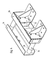
- the movable connecting member 14 is moved again in the overstroke region 22.
- the anchored in the pressure cell 30 connecting hook 28 is released by re-pushing it into the pressure cell 30 of this unlocking.
- the connecting hook 38 in the pressure box 40 is a lock with this.
- the coupling member 26 is now again connected to the stationary terminal member 12 and released from the movable terminal member 14. Now, when moving back the movable connecting member 14 from the overstroke 22, the Schutzabdekkung 10 are operated again variable in length.
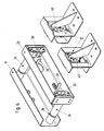
- two pressure cans 30 and 40 are present to achieve a uniform operation, each of which two connecting hooks 28 and 38 are assigned.
- more than two pressure sockets may be present, especially with very large machine covers.
- the arrangement of the pressure cans 30 and 40 on the coupling member 26 and on the stationary member 12 is not mandatory and can be changed for one or both pressure cans. Then also other arrangements of the connecting hooks 28, 38 would be provided accordingly.
- a combined double-sided, reversibly releasable mechanical pressure box could be attached to the coupling member 26, the corresponding connecting hooks 28 and 38 are assigned to the movable and stationary connection members 14 and 12.
Abstract
Description
Maschinenabdeckung mit einer längenveränderlichen Schutzabdeckung, deren Enden im betrieblichen Arbeitsbereich der Schutzabdeckung mit einem stationären Anschlußglied und einem beweglichen Anschlußglied verbunden sind, wobei das bewegliche Anschlußglied maschinenseitig zwischen einer betrieblichen Minimalposition mit minimaler und einer betrieblichen Maximalposition mit maximaler Längenausdehnung der Schutzabdeckung linear hin- und herbeweglich angetrieben istA machine cover having a variable length protective cover whose ends are connected to a stationary terminal member and a movable terminal member in the operative working area of the protective cover, wherein the movable terminal member linearly reciprocally driven machine side between a minimum operating position and a maximum operating position with maximum length of the protective cover is
Solche Maschinenabdeckungen sind vielfach als im Bedarfsfall von oben zugängliche Dachabdeckungen ausgeführt. Im normalen Betriebszustand schließen diese den Arbeitsraum nach oben ab. Beispielsweise für von oben erfolgende Kranbeladungen von großen und schweren Werkstücken ist es erforderlich, die Schutz- oder Dachabdeckungen lösbar und verschiebbar auszubilden. In diesem Zusammenhang ist es beispielsweise bekannt, zum Öffnen entsprechende Schraubverbindungen oder Bolzensicherungen von Hand zu lösen und dann die Schutzabdeckung von Hand öffnend zu verschieben, um anschließend zum Schließen diese Vorgänge wieder rückgängig zu machen. Diese Vorgänge erfolgen teils auch durch ein gesteuertes Öffnen und Schließen durch Elektrik, Pneumatik oder Hydraulik. Es gibt auch separat gesteuerte und angetriebene Konsolen (Endrahmen) mit eigenem Antrieb. Alle diese Lösungen sind kompliziert und teuer. Sie erfordern entweder aufwendige elektrische, pneumatische oder hydraulische Zusatzteile, spezielle herstellerspezifische Schnittstellen oder ein manuelles Eingreifen.Such machine covers are often designed as if necessary from above accessible roofing. In the normal operating state, these close the working space upwards. For example, from above for crane loading of large and heavy workpieces, it is necessary to form the protective or roof covers releasably and displaceably. In this context, it is known, for example, to release appropriate screw connections or bolt locks by hand to open and then to move the protective cover opening by hand, and then to undo these operations to close again. These processes are partly also by a controlled opening and closing by electrical, pneumatic or hydraulic. There are also separately controlled and powered consoles (end frames) with their own drive. All of these solutions are complicated and expensive. They either require expensive electrical, pneumatic or hydraulic additional parts, special manufacturer-specific interfaces or manual intervention.
Der vorliegenden Erfindung liegt die Aufgabe zugrunde, eine Maschinenabdeckung der genannten Art so auszubilden, daß sie in maschinentechnisch einfacher Art ohne manuelles Eingreifen mit kostengünstigen Mitteln auf rein mechanischem Wege leicht sowie schnell zu öffnen und wieder zu schließen ist.The present invention has for its object to provide a machine cover of the type mentioned in such a way that it can be easily and quickly opened and closed again in a simple mechanical way without manual intervention with cost-effective means purely mechanical way.
Zur Lösung der gestellten Aufgabe wird bei einer Maschinenabdeckung der im Oberbegriff genannten Art erfindungsgemäß vorgeschlagen, daß das im Arbeitsbereich stationäre Ende der Schutzabdeckung fest mit einem doppelseitig reversibel arbeitenden Koppelglied verbunden ist, welches im Arbeitsbereich der Schutzabdeckung eine lösbare mechanische Verbindung mit dem stationären Anschlußglied aufweist, daß im Falle einer maschinenseitig veranlaßten Öffnungsbewegung des beweglichen Anschlußgliedes in einen an dessen betriebliche Minimalposition angrenzenden Überhubbereich durch bewegungsabhängig erfolgende gegenseitige mechanische Druckeingriffe zwischen dem beweglichen Anschlußglied sowie dem Koppelglied und zwischen diesem sowie dem stationären Anschlußglied eine lösbare mechanische Verbindung des Koppelgliedes mit dem beweglichen Anschlußglied erfolgt und die lösbare mechanische Verbindung des Koppelgliedes mit dem stationären Anschlußglied entfällt, so daß die längenmäßig komprimierte Schutzabdeckung vom beweglichen Anschlußglied öffnend zurückziehbar ist, und daß im Falle einer maschinenseitig veranlaßten, der Öffnungsbewegung nachfolgenden Schließbewegung des beweglichen Anschlußgliedes in den Überhubbereich durch erneute bewegungsabhängig erfolgende gegenseitige mechanische Druckeingriffe zwischen dem beweglichen Anschlußglied sowie dem Koppelglied und zwischen diesem sowie dem stationären Anschlußglied die lösbare mechanische Verbindung des Koppelgliedes mit dem beweglichen Anschlußglied wieder entfällt und die lösbare mechanische Verbindung des Koppelgliedes mit dem stationären Anschlußglied wieder erfolgt.In order to achieve the object, in the case of a machine cover of the type mentioned in the preamble, the invention proposes that the end of the protective cover stationary in the working area is firmly connected to a double-sided reversible coupling member which has a releasable mechanical connection to the stationary connecting member in the working area of the protective cover. that in the case of a machine-induced opening movement of the movable connecting member in an adjacent to the operating minimum position overhub by taking place depending mutual mechanical pressure interventions between the movable terminal member and the coupling member and between this and the stationary terminal member is a releasable mechanical connection of the coupling member to the movable terminal member and the detachable mechanical connection of the coupling member with the stationary connection member deleted, so that the length moderately compressed protective cover of the movable terminal member is retractable opening, and that in the case of a machine-induced, the opening movement subsequent closing movement of the movable connecting member in the overstroke by renewed movement-related mutual mechanical pressure interventions between the movable terminal member and the coupling member and between this and the stationary terminal member releasable mechanical connection of the coupling member with the movable terminal member deleted again and the releasable mechanical connection of the coupling member with the stationary terminal member again.
Eine derartige Maschinenabdeckung ist einfach, zuverlässig sowie preiswert, erfordert zum Entriegeln sowie Verriegeln keine manuellen Eingriffe und arbeitet mit integrierten Teilen rein mechanisch ohne externe Antriebe. Sie bedient sich des bei jeder Maschine in jeder Maschinenachse vorhandenen und maschinenseitig ansteuerbaren Überhubes, bei dem die längenveränderliche Schutzabdeckung über ihren normalen Arbeitsbereichs hinausgehend noch etwas weiter in einen normalerweise nicht genutzten Überhubbereich verkürzt werden kann. Dort erfolgen die entsprechenden Entriegelung- und Verriegelungsvorgänge zwischen dem Koppelglied und dem stationären Anschlußglied sowie dem beweglichen Anschlußglied durch einfache mechanische Bewegungsdruckvorgänge.Such a machine cover is simple, reliable and inexpensive, requires no manual intervention for unlocking and locking and works with integrated parts purely mechanically without external drives. It uses the available on each machine in each machine axis and machine side controllable overstroke, in which the variable-length protective cover beyond their normal work area going further can be shortened a little further into a normally unused Überhubbereich. There, the corresponding unlocking and locking operations between the coupling member and the stationary terminal member and the movable terminal member carried by simple mechanical movement pressure operations.
Gemäß der weiteren Ausbildung nach den Ansprüchen 2 und 3 haben sich hierbei in der Praxis einfache, handelsübliche, reversibel auslösbare mechanische Druckdosen bewährt, die mit relativ hierzu bewegten Verbindungshaken zusammenwirken, um diese bei aufeinanderfolgenden bewegungsbedingten Druckeingriffen abwechselnd zu verriegeln und wieder freizugeben. Da es nur auf die relativen gegenseitigen Positionen von Verbindungshaken und Druckdosen ankommt, können diese Elemente an verschiedenen Stellen montiert sein.According to the further embodiment according to claims 2 and 3, in practice simple, commercially available, reversibly releasable mechanical pressure cans have proven to work together with connecting hooks moved relative thereto in order to alternately lock and release them during successive movement-related pressure interventions. Since only the relative mutual positions of connecting hooks and pressure boxes are important, these elements can be mounted in different places.
In weiterer Ausgestaltung gemäß Anspruch 4 können die mechanischen Druckdosen im Überhubbereich gleichzeitig oder gemäß Anspruch 5 nacheinander ansprechen. Im zweiten Fall kann nach Anspruch 6 im Überhubbereich die Druckdose für die lösbare mechanische Verbindung des Koppelgliedes mit dem beweglichen Anschlußglied vor derjenigen für die lösbare mechanische Verbindung des Koppelgliedes mit dem stationären Anschlußglied ansprechen.In a further embodiment according to claim 4, the mechanical pressure cans in the overstroke range simultaneously or according to claim 5 respond successively. In the second case can according to claim 6 in Überhubbereich the pressure cell for the releasable mechanical connection of the coupling member to the movable terminal member respond to those for the releasable mechanical connection of the coupling member with the stationary terminal member.
Statt der Verwendung einzelner Druckdosen für die wechselseitigen Entriegelungs-und Verriegelungsvorgänge ist es nach Anspruch 7 auch möglich, am Koppelglied wenigstens eine reversibel auslösbare doppelseitige mechanische Druckdose einzusetzen, die mit entsprechenden Verbindungshaken an den beweglichen und stationären Anschlußgliedern zusammenarbeitet.Instead of using individual pressure boxes for the mutual unlocking and locking operations, it is also possible according to claim 7 to use at least one reversibly releasable double-sided mechanical pressure box on the coupling member, which cooperates with corresponding connection hooks on the movable and stationary connection members.
Die weitere Ausgestaltung nach Anspruch 8 soll im Überhubbereich - also außerhalb des normalen Arbeitsbereiches - eine exakte Bewegungsführung des beweglichen Anschlußgliedes gegenüber dem Koppelglied und eine anschlagbedingte Mitnahme des Koppelgliedes sicherstellen.The further embodiment according to claim 8 is in the overstroke - ie outside the normal working area - ensure an accurate motion control of the movable connecting member relative to the coupling member and a stop-related entrainment of the coupling member.
Die Erfindung wird nachfolgend an zeichnerisch dargestellten Ausführungsbeispielen näher erläutert. Es zeigen:
- Fig. 1
- in einer vereinfachten perspektivischen Darstellung eine Maschinenabdeckung in ihrem normalen betrieblichen Arbeitsbereich,
- Fig. 2
- die Maschinenabdeckung aus
Fig. 1 aus einer anderen Blickrichtung, - Fig. 3
- die Maschinenabdeckung aus den
Fig. 1 und2 am Ende ihres ihre längenveränderliche Schutzabdeckung verkürzenden normalen Arbeitsbereiches bzw. beim Eintritt in einen Überhubbereich, - Fig. 4
- die Maschinenabdeckung aus
Fig. 3 beim entriegelnden Erreichen des Endes ihres Überhubbereiches, - Fig. 5
- die Maschinenabdeckung aus
Fig. 4 nach erfolgtem Entriegeln zu Beginn des öffnenden Zurückbewegens und - Fig. 6
- die Maschinenabdeckung aus
Fig. 5 in ihrem entriegelten und geöffneten Betriebszustand.
- Fig. 1
- in a simplified perspective view of a machine cover in its normal operational workspace,
- Fig. 2
- the machine cover off
Fig. 1 from a different perspective, - Fig. 3
- the machine cover from the
Fig. 1 and2 at the end of their normal working area shortening their variable-length protective cover or when entering an overstroke area, - Fig. 4
- the machine cover off
Fig. 3 when unlocking the end of its overstroke area, - Fig. 5
- the machine cover off
Fig. 4 after unlocking at the beginning of the opening backward movement and - Fig. 6
- the machine cover off
Fig. 5 in their unlocked and open operating state.
Gemäß
An die betriebliche Minimalposition 18 grenzt ein Überhubbereich 22 mit einer maximalen Überhubposition 24 an. Der Überhubbereich 22 ist außerhalb des normalen Betriebs- oder Arbeitszustands im Bedarfsfall maschinenseitig ansteuerbar, um die Schutzabdeckung 10 beispielsweise für von oben erfolgende Kranbeladungen von großen und schweren Werkstücken gemäß
Beim Öffnungsvorgang wird das Koppelglied 26 bei längenverkürzter Schutzabdekkung 10 vom stationären Anschlußglied 12 mechanisch getrennt und mit dem beweglichen Anschlußglied 14 mechanisch verbunden. In diesem Öffnungszustand kann das bewegliche Anschlußglied 14 das Koppelglied 26 mit der verkürzten Schutzabdeckung 10 zurückziehen, so daß zwischen dem Koppelglied 26 und dem stationären Anschlußglied 12 gemäß
Beim Öffnungsvorgang der Schutzabdeckung 10 ist das bewegliche Anschlußglied 14 mit wenigstens einem Bewegungsanschlag 36 in den Überhubbereich 22 einfahrbar. Beim Erreichen oder innerhalb desselben stößt der Bewegungsanschlag 36 gegen die Stirnseite einer Führungshülse 34 an dem Koppelglied 26. Zuvor ist ein Führungskonus 32 mit einem vorderseitigen Verbindungshaken 28 am beweglichen Anschlußglied 14 in die Führungshülse 34 eingedrungen. Am Koppelglied 26 ist wenigstens eine aus den
Nunmehr kann beim Zurückbewegen des beweglichen Anschlußgliedes 14 aus dem Überhubbereich 22 der Verbindungshaken 28 über die hiermit verriegelte Druckdose 30 das vom stationären Anschlußglied 12 gelöste Koppelglied 26 - und damit auch die komprimierte Schutzabdeckung 10 - gemäß
Zum Verschließen der Maschinenabdeckung wird das bewegliche Anschlußglied 14 erneut in den Überhubbereich 22 gefahren. Hierbei wird der in der Druckdose 30 verankerte Verbindungshaken 28 durch erneutes Hineindrücken in die Druckdose 30 von dieser entriegelnd gelöst. Außerdem erfolgt durch erneutes Hineindrücken des Verbindungshakens 38 in die Druckdose 40 ein Verriegeln mit dieser.To close the machine cover, the movable connecting
Das Koppelglied 26 ist jetzt wieder mit dem stationären Anschlußglied 12 verbunden und vom beweglichen Anschlußglied 14 gelöst. Nunmehr kann beim Zurückbewegen des beweglichen Anschlußgliedes 14 aus dem Überhubbereich 22 die Schutzabdekkung 10 erneut längenveränderlich betrieben werden.The
Gemäß den zeichnerischen Darstellungen sind zum Erzielen eines gleichmäßigen Betriebes jeweils zwei Druckdosen 30 und 40 vorhanden, denen jeweils zwei Verbindungshaken 28 und 38 zugeordnet sind. Es können vor allem bei sehr großen Maschinenabdeckungen grundsätzlich auch mehr als jeweils zwei Druckdosen vorhanden sein.According to the drawings, two
Die Anordnung der Druckdosen 30 bzw. 40 an dem Koppelglied 26 bzw. an dem stationären Glied 12 ist nicht verbindlich und kann für eine oder beide Druckdosen geändert werden. Dann wären auch entsprechend andere Anordnungen der Verbindungshaken 28, 38 vorzusehen.The arrangement of the
Statt getrennter Druckdosen 30, 40 könnte hierfür auch eine kombinierte doppelseitige, reversibel auslösbare, mechanische Druckdose am Koppelglied 26 angebaut werden, der entsprechende Verbindungshaken 28 und 38 an den beweglichen und stationären Anschlußgliedern 14 und 12 zuzuordnen sind.Instead of
Claims (8)
dadurch gekennzeichnet,
daß das im Arbeitsbereich (16) stationäre Ende der Schutzabdeckung (10) fest mit einem doppelseitig reversibel arbeitenden Koppelglied (26) verbunden ist, welches im Arbeitsbereich (16) der Schutzabdeckung (10) eine lösbare mechanische Verbindung mit dem stationären Anschlußglied (12) aufweist,
daß im Falle einer maschinenseitig veranlaßten Öffnungsbewegung des beweglichen Anschlußgliedes (14) in einen an dessen betriebliche Minimalposition (18) angrenzenden Überhubbereich (22) durch bewegungsabhängig erfolgende gegenseitige mechanische Druckeingriffe zwischen dem beweglichen Anschlußglied (14) sowie dem Koppelglied (26) und zwischen diesem sowie dem stationären Anschlußglied (12) eine lösbare mechanische Verbindung des Koppelgliedes (26) mit dem beweglichen Anschlußglied (14) erfolgt und die lösbare mechanische Verbindung des Koppelgliedes (26) mit dem stationären Anschlußglied (12) entfällt, so daß die längenmäßig komprimierte Schutzabdekkung (10) vom beweglichen Anschlußglied (14) öffnend zurückziehbar ist,
und daß im Falle einer maschinenseitig veranlaßten, der Öffnungsbewegung nachfolgenden Schließbewegung des beweglichen Anschlußgliedes (14) in den Überhubbereich (22) durch erneute bewegungsabhängig erfolgende gegenseitige mechanische Druckeingriffe zwischen dem beweglichen Anschlußglied (14) sowie dem Koppelglied (26) und zwischen diesem sowie dem stationären Anschlußglied (12) die lösbare mechanische Verbindung des Koppelgliedes (26) mit dem beweglichen Anschlußglied (14) wieder entfällt und die lösbare mechanische Verbindung des Koppelgliedes (26) mit dem stationären Anschlußglied (12) wieder erfolgt.A machine cover having a variable length protective cover (10) having its ends connected to a stationary terminal member (12) and a movable terminal member (14) in the operative working area (16) of the protective cover, the movable terminal member (14) being provided on the machine side between a minimum operative position (18 ) is linearly reciprocally driven with minimum and maximum operating positions (20) with maximum longitudinal extent of the protective cover,
characterized,
that in the working area (16) stationary end of the protective cover (10) is fixedly connected to a double-sided reversible coupling member (26) which in the working area (16) of the protective cover (10) has a releasable mechanical connection with the stationary terminal member (12) .
that in the case of a machine side caused opening movement of the movable terminal member (14) in one of its operational minimum position (18) adjacent overstroke (22) by motion dependent taking place mutual mechanical pressure interference between the movable connecting member (14) and the coupling member (26) and between this and the stationary terminal member (12) is a releasable mechanical connection of the coupling member (26) with the movable terminal member (14) and the releasable mechanical connection of the coupling member (26) with the stationary terminal member (12) is omitted, so that the lengthwise compressed Schutzabdekkung (10 ) is retractable opening from the movable connecting member (14),
and that in the case of a machine side caused, the opening movement subsequent closing movement of the movable connecting member (14) in the overstroke (22) by renewed movement-related mutual mechanical pressure interventions between the movable terminal member (14) and the coupling member (26) and between this and the stationary Connecting member (12) the releasable mechanical connection of the coupling member (26) with the movable terminal member (14) again omitted and the releasable mechanical connection of the coupling member (26) with the stationary terminal member (12) takes place again.
Applications Claiming Priority (1)
| Application Number | Priority Date | Filing Date | Title |
|---|---|---|---|
| DE102007043808A DE102007043808A1 (en) | 2007-09-13 | 2007-09-13 | Machine cover with a variable-length protective cover |
Publications (2)
| Publication Number | Publication Date |
|---|---|
| EP2037166A2 true EP2037166A2 (en) | 2009-03-18 |
| EP2037166A3 EP2037166A3 (en) | 2009-12-23 |
Family
ID=40097173
Family Applications (1)
| Application Number | Title | Priority Date | Filing Date |
|---|---|---|---|
| EP08015810A Withdrawn EP2037166A3 (en) | 2007-09-13 | 2008-09-09 | Machine covering with a protective covering adjustable in length |
Country Status (2)
| Country | Link |
|---|---|
| EP (1) | EP2037166A3 (en) |
| DE (1) | DE102007043808A1 (en) |
Cited By (1)
| Publication number | Priority date | Publication date | Assignee | Title |
|---|---|---|---|---|
| EP2907618A1 (en) * | 2014-02-17 | 2015-08-19 | Arno Arnold GmbH | Machine covering |
Families Citing this family (5)
| Publication number | Priority date | Publication date | Assignee | Title |
|---|---|---|---|---|
| DE102009060097B4 (en) | 2009-12-21 | 2013-07-18 | Möller Werke GmbH | cover device |
| DE202014007338U1 (en) | 2014-09-15 | 2014-10-07 | Möller Werke GmbH | Machine protection cover |
| DE202019105099U1 (en) * | 2019-09-13 | 2021-01-15 | Möller Werke GmbH | Covering device for a machine cabin |
| DE202020102152U1 (en) | 2020-04-17 | 2021-07-20 | Möller Werke GmbH | Protective cover system |
| DE102020112377B4 (en) | 2020-05-07 | 2022-07-07 | Arno Arnold Gmbh | Protective cover with locking device to cover moving machine parts |
Citations (2)
| Publication number | Priority date | Publication date | Assignee | Title |
|---|---|---|---|---|
| WO1992021480A1 (en) * | 1991-05-30 | 1992-12-10 | Stama Maschinenfabrik Gmbh | Machine-tool with fixed workbench and vertical operating spindle |
| DE4436944A1 (en) * | 1994-10-15 | 1996-04-18 | Saechsische Werkzeug Und Sonde | Machine table cover for laser processing |
Family Cites Families (4)
| Publication number | Priority date | Publication date | Assignee | Title |
|---|---|---|---|---|
| DE2505545A1 (en) * | 1975-02-10 | 1976-08-19 | Keil Heinz Toni | Accident protection plate for machine tools - has series of metal strips with roller support and release mechanism |
| DE4026609C1 (en) * | 1989-09-02 | 1991-05-02 | Hcr-Heinrich Cremer Gmbh, 4050 Moenchengladbach, De | Casing for guide track telescopic covers - has each side wall with longitudinal slit on edge adjacent to front wall |
| DE29610893U1 (en) * | 1996-06-21 | 1996-08-14 | Kubitschek Hans Joerg | Sliding roller blind box to cover machines |
| DE20200701U1 (en) * | 2002-01-18 | 2002-05-02 | Hema Maschinen & Apparate | Stabilizing scissors for a protective cover |
-
2007
- 2007-09-13 DE DE102007043808A patent/DE102007043808A1/en not_active Withdrawn
-
2008
- 2008-09-09 EP EP08015810A patent/EP2037166A3/en not_active Withdrawn
Patent Citations (2)
| Publication number | Priority date | Publication date | Assignee | Title |
|---|---|---|---|---|
| WO1992021480A1 (en) * | 1991-05-30 | 1992-12-10 | Stama Maschinenfabrik Gmbh | Machine-tool with fixed workbench and vertical operating spindle |
| DE4436944A1 (en) * | 1994-10-15 | 1996-04-18 | Saechsische Werkzeug Und Sonde | Machine table cover for laser processing |
Cited By (1)
| Publication number | Priority date | Publication date | Assignee | Title |
|---|---|---|---|---|
| EP2907618A1 (en) * | 2014-02-17 | 2015-08-19 | Arno Arnold GmbH | Machine covering |
Also Published As
| Publication number | Publication date |
|---|---|
| DE102007043808A1 (en) | 2009-03-19 |
| EP2037166A3 (en) | 2009-12-23 |
Similar Documents
| Publication | Publication Date | Title |
|---|---|---|
| EP0526522B1 (en) | Pivoting lever catch securable with a cylinder lock device | |
| AT403040B (en) | TELESCOPIC STICK | |
| CH680522A5 (en) | ||
| EP2037166A2 (en) | Machine covering with a protective covering adjustable in length | |
| DE60109697T2 (en) | Motor vehicle with independent pivoting and sliding doors | |
| EP3622149A1 (en) | Rail for guiding a carriage of a furniture door | |
| DE102009026975A1 (en) | Locking device for a telescopic boom and manual bolt release mechanism for this | |
| EP1153875B1 (en) | Locking and actuating unit for a lateral jib locking device | |
| EP0274710A1 (en) | Portable powered pliers for tightening clamp rings or the like | |
| EP0941889A2 (en) | Extraction device | |
| EP2907618A1 (en) | Machine covering | |
| DE102011116083B4 (en) | Securing and locking unit for outriggers with telescopic shots, especially for mobile cranes | |
| EP2733286B1 (en) | Pivoting lever closure with low installation depth | |
| DE2619031C2 (en) | ||
| DE3020788C2 (en) | Inner locking device for a point machine | |
| DE102012002122B4 (en) | Locking device for a telescopic boom | |
| DE10352488B3 (en) | Closure for hoods, flaps or the like on vehicles | |
| EP4048122B1 (en) | Combination of movement device and synchronisation device for pull-out guides for a drawer | |
| EP2235729A1 (en) | Safety switch having a hold-closed function for positive opening of contact elements, and method for positive opening of contact elements of a safety switch with a locking function | |
| DE202014007338U1 (en) | Machine protection cover | |
| DE19908191C1 (en) | Automatic panel or door system has stop or drive element that can be moved along path by defined distance when end position is reached; path contains trigger for actuator | |
| DE102021101548A1 (en) | Protective cover system | |
| EP3460137B1 (en) | Mobile partition wall element with release device | |
| DE19727590C1 (en) | Crash coupling for roll bar of motor vehicle | |
| DE202008007906U1 (en) | Locking device with rotor operation to the side |
Legal Events
| Date | Code | Title | Description |
|---|---|---|---|
| PUAI | Public reference made under article 153(3) epc to a published international application that has entered the european phase |
Free format text: ORIGINAL CODE: 0009012 |
|
| AK | Designated contracting states |
Kind code of ref document: A2 Designated state(s): AT BE BG CH CY CZ DE DK EE ES FI FR GB GR HR HU IE IS IT LI LT LU LV MC MT NL NO PL PT RO SE SI SK TR |
|
| AX | Request for extension of the european patent |
Extension state: AL BA MK RS |
|
| PUAL | Search report despatched |
Free format text: ORIGINAL CODE: 0009013 |
|
| AK | Designated contracting states |
Kind code of ref document: A3 Designated state(s): AT BE BG CH CY CZ DE DK EE ES FI FR GB GR HR HU IE IS IT LI LT LU LV MC MT NL NO PL PT RO SE SI SK TR |
|
| AX | Request for extension of the european patent |
Extension state: AL BA MK RS |
|
| AKX | Designation fees paid |
Designated state(s): AT BE BG CH CY CZ DE DK EE ES FI FR GB GR HR HU IE IS IT LI LT LU LV MC MT NL NO PL PT RO SE SI SK TR |
|
| STAA | Information on the status of an ep patent application or granted ep patent |
Free format text: STATUS: THE APPLICATION IS DEEMED TO BE WITHDRAWN |
|
| 18D | Application deemed to be withdrawn |
Effective date: 20100624 |