EP2037161B1 - Dichtung mit integriertem Sensor und Dichtungsanordnung mit dieser Dichtung - Google Patents
Dichtung mit integriertem Sensor und Dichtungsanordnung mit dieser Dichtung Download PDFInfo
- Publication number
- EP2037161B1 EP2037161B1 EP07018197A EP07018197A EP2037161B1 EP 2037161 B1 EP2037161 B1 EP 2037161B1 EP 07018197 A EP07018197 A EP 07018197A EP 07018197 A EP07018197 A EP 07018197A EP 2037161 B1 EP2037161 B1 EP 2037161B1
- Authority
- EP
- European Patent Office
- Prior art keywords
- push
- supporting body
- sensor
- sealing
- accommodating tube
- Prior art date
- Legal status (The legal status is an assumption and is not a legal conclusion. Google has not performed a legal analysis and makes no representation as to the accuracy of the status listed.)
- Active
Links
Images


Classifications
-
- F—MECHANICAL ENGINEERING; LIGHTING; HEATING; WEAPONS; BLASTING
- F16—ENGINEERING ELEMENTS AND UNITS; GENERAL MEASURES FOR PRODUCING AND MAINTAINING EFFECTIVE FUNCTIONING OF MACHINES OR INSTALLATIONS; THERMAL INSULATION IN GENERAL
- F16J—PISTONS; CYLINDERS; SEALINGS
- F16J15/00—Sealings
- F16J15/16—Sealings between relatively-moving surfaces
- F16J15/32—Sealings between relatively-moving surfaces with elastic sealings, e.g. O-rings
- F16J15/3296—Arrangements for monitoring the condition or operation of elastic sealings; Arrangements for control of elastic sealings, e.g. of their geometry or stiffness
-
- G—PHYSICS
- G01—MEASURING; TESTING
- G01K—MEASURING TEMPERATURE; MEASURING QUANTITY OF HEAT; THERMALLY-SENSITIVE ELEMENTS NOT OTHERWISE PROVIDED FOR
- G01K1/00—Details of thermometers not specially adapted for particular types of thermometer
- G01K1/14—Supports; Fastening devices; Arrangements for mounting thermometers in particular locations
-
- G—PHYSICS
- G01—MEASURING; TESTING
- G01L—MEASURING FORCE, STRESS, TORQUE, WORK, MECHANICAL POWER, MECHANICAL EFFICIENCY, OR FLUID PRESSURE
- G01L19/00—Details of, or accessories for, apparatus for measuring steady or quasi-steady pressure of a fluent medium insofar as such details or accessories are not special to particular types of pressure gauges
- G01L19/0007—Fluidic connecting means
-
- G—PHYSICS
- G01—MEASURING; TESTING
- G01K—MEASURING TEMPERATURE; MEASURING QUANTITY OF HEAT; THERMALLY-SENSITIVE ELEMENTS NOT OTHERWISE PROVIDED FOR
- G01K2217/00—Temperature measurement using electric or magnetic components already present in the system to be measured
Definitions
- the invention relates to a plug-in piece and a sealing arrangement with such a plug-in piece, comprising a sleeve-shaped support body made of tough material and a sealing body made of rubber-elastic material which surrounds the support body at least partially.
- a seal assembly is from the EP 1 593 886 A1 known.
- the sealing arrangement comprises a seal with a sealing lip and a sensor device with a measuring tongue protruding into a space to be sealed, wherein the measuring tongue can be acted upon by the medium to be sealed during the intended use.
- the measuring tongue is designed as a transmitter for detecting the age of the medium to be sealed, the temperature and / or the pressure and / or the filling quantity of the medium to be sealed.
- Another seal which is designed as a cassette seal, is from the EP 1 653 096 A1 known.
- the seal is used to seal a rolling bearing for use, with a speed sensor integrated in the seal.
- the speed sensor is arranged in a housing and signal conducting with connected to an evaluation electronics.
- the housing of the speed sensor penetrates the support body of the seal, which consists of a metallic material and which is connected radially inwardly with the sealing lips of elastomeric material.
- the sealing lips touch sealing surfaces of a race which is pressed onto the inner ring of the rolling bearing.
- the support body and the speed sensor are in contrast pressed into the outer ring of the bearing.
- the housing of the sensor may be made of a plastic, wherein a sealing packing between the support body and the housing of the sensor is arranged to prevent contaminants from the environment on the housing of the sensor and the support body penetrate into the interior of the rolling bearing.
- Plug-in pieces and sealing arrangements with plug-in pieces are generally known, wherein the plug-in pieces adjacent to each other housing parts, such as an engine block and a transmission of a motor vehicle, liquid-tightly interconnect (see, eg DE-C-10117731 ).
- the plug-in sensors that detect, for example, temperatures and / or pressures in machine elements to be sealed.
- Such sensors are arranged in holders on the housings of the machine elements. The attachment of the holder on the housing usually takes place through receiving holes in the housing, wherein the holders are screwed into the mounting holes. In manufacturing and economic terms, this is disadvantageous.
- the invention is based on the object of further developing a plug-in piece and a sealing arrangement in such a way that the plug-in piece according to the invention and the sealing arrangement according to the invention thus enable a simple and cost-effective detection of interesting measured values, with additional sealing of the transitional area from the supporting body to the receiving tube in which the sensor is arranged is.
- a plug-in piece with integrated sensor comprising a sleeve-shaped support body of tough material and a sealing body made of rubber-elastic material which surrounds the support body at least partially, wherein the support body is connected to a wall penetrating its receiving tube for the sensor, wherein the Receiving tube from the sealing body form-fitting or cohesively sealed sealing.
- Plug-in pieces are used to sealingly interconnect adjacent machine components, such as the transmission and engine of a motor vehicle.
- the plug connects the housing of the adjacent machine elements.
- the support body is flowed through, for example, from medium to be sealed.
- the receiving tube protrudes into the interior of the plug-in piece in order to record measured values, such as, for example, the temperature of the medium flowing through and / or the pressure inside the plug-in piece.
- the sealing arrangement comprises a plug-in piece as described above, wherein the plug-in piece sealingly connects housing parts and wherein the plug-in piece has a sleeve-shaped support body, which is encased on the outer peripheral side of the sealing body, wherein the sealing body in the region of its two end faces in each case has a sealing bead.
- the plug has an integrated sensor.
- the plug-in piece and the sensor form a preassembled unit. In comparison to the installation of a separate sensor and in addition of a plug-in piece without integrated sensor, the assembly is considerably simplified overall and the risk of assembly errors is limited to a minimum. The requirement for costly
- the receiving tube for the sensor penetrates the wall of the support body and ends, in the mounted and ready-to-use state, in the space to be sealed, in which the measured values can be detected.
- the receiving tube is enclosed by the sealing body in a form-fitting or cohesive sealing manner. It is advantageous that the transition region from the support body is additionally sealed to the receiving tube.
- the receiving tube may have a trained as a positioning aid collar, which is annular and surrounds the support body sealingly on the outer peripheral side.
- the collar and the adjoining the lower part of the receiving tube, which is arranged radially outside of the support body, may be enclosed by the elastomeric material of the sealing body.
- the support body and the receiving tube may be cohesively connected to each other.
- the cohesive connection can take place, for example, in that the receiving tube is welded into the supporting body. It is advantageous that this compound is absolutely tight during the entire service life.
- the support body and the receiving tube can be non-positively and / or positively connected with each other.
- Force and / or positive connections have the advantage that the receiving tube and the support body can be separated from each other in a non-destructive manner. This is particularly advantageous if the Receiving tube and the sensor form a preassembled unit and during the service life of the seal / seal assembly, for example due to a defect, would have to be replaced.
- the support body and / or the receiving tube may consist of a metallic or polymeric material.
- cohesive connections between the support body and receiving tube it makes sense if these two components to be joined together are formed of the same material.
- the receiving tube contrast, from a polymeric material.
- the receiving tube may be provided with an integral seal to sealingly close the transition region between the support body and the receiving tube.
- the sensor may be non-positively and / or positively arranged in the receiving tube. This allows a simple adaptation of the sensor to the particular circumstances of the application. It is possible to use one and the same plug-in piece, whereby depending on the application either a temperature sensor, a pressure sensor or other transducers can be mounted within the receiving tube. Also, sensors for different measuring ranges, depending on the application, can be inserted into the receiving tube. This modular system ensures a simple and cost-effective adaptation of the plug-in piece to the particular application.
- pressure and / or temperature sensors can be used.
- the receiving tube inside the plug-in piece may be open at the end or tightly sealed.
- the sealing bead in the region of the two end faces of the sealing body can, viewed in longitudinal section, be formed curved radially outwards or inwards.
- a radially outwardly projecting receiving tube In the axial direction between the sealing beads, a radially outwardly projecting receiving tube can be arranged.
- the sealing beads are usually arranged sealingly in bores of adjacent housings.
- the receiving tube is then in the gap formed by the distance between the housings.
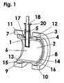
- FIGS. 1 to 4 are two embodiments of male pieces 6 / seal assemblies so shown.
- a male piece 6 is shown, the one Support body 2 comprises a tough material.
- the support body 2 consists of a metallic material; deviating from this, however, a polymeric material can also be used.
- the sealing body 3 consists in the embodiment shown in each case of an elastomeric material which completely surrounds the support body 2 on the outer peripheral side.
- the end faces 13,14 of the support body 2 are each free of elastomeric material of the sealing body 3; like in the FIGS.
- the plug-in piece 6 has an integrated sensor 1.
- the plug-in piece 6 is arranged in the two exemplary embodiments shown between two housing parts 7, 8 which are shown schematically and are to be sealed against each other.
- the sealing body 3 has, in the region of its two end faces 15, 16, in each case a sealing bead 11, 12, wherein each sealing bead 11, 12 is designed to bulge radially outward. In the axial direction between the sealing beads 11,12 the receiving tube 5 for the sensor 1 projects radially outward.
- FIG. 1 the first embodiment of the male piece 6 / the seal assembly is thus shown in a longitudinal section; in FIG. 2 the plug 6 / the seal assembly is thus shown in a view.
- the sensor 1 is designed as a temperature sensor and arranged in the receiving tube 5.
- the receiving tube 5 is just like the support body 2, made of a metallic material and is materially connected thereto. The connection is formed by a welded joint.
- the receiving tube 5 is closed at the end within the plug-in piece 6, so that the temperature sensor is protected against exposure to medium to be sealed.
- the receiving tube 5 has a collar 17, which is annular in shape and touches the supporting body 2 on the outer peripheral side. Both the collar 17 and the lower part of the receiving tube 5, which is arranged radially outside of the support body 2, are enclosed by elastomeric material of the sealing body 3. The upper part of the receiving tube 5, from which the cables 18 are guided in the direction of a plug 19, is closed with a sealing plug 20.
- FIG. 3 the second embodiment of the male piece 6 / the seal assembly is thus shown in a longitudinal section; in FIG. 4 the plug 6 / the seal assembly is thus shown in a view.
- the sensor 1 is designed as a pressure sensor and arranged in the receiving tube 5.
- the receiving tube 5 penetrates the wall 4 of the support body 2.
- the receiving tube 5 has a funnel-shaped enlargement 21, in which the pressure sensor is arranged.
- the receiving tube is open on the extension 21 axially facing away from the end face, so that the pressure sensor with the effective pressure within the plug 6 pressure can be acted upon.
Landscapes
- Engineering & Computer Science (AREA)
- General Engineering & Computer Science (AREA)
- Physics & Mathematics (AREA)
- General Physics & Mathematics (AREA)
- Mechanical Engineering (AREA)
- Measuring Temperature Or Quantity Of Heat (AREA)
- Measuring Oxygen Concentration In Cells (AREA)
- Measuring Fluid Pressure (AREA)
- Gasket Seals (AREA)
Description
- Die Erfindung betrifft ein Steckstück und eine Dichtungsanordnung mit einem solchem Steckstück, umfassend einen hülsenförmigen Stützkörper aus zähhartem Werkstoff und einen Dichtkörper aus gummielastischem Werkstoff, der den Stützkörper zumindest teilweise umschließt.
- Eine Dichtungsanordnung ist aus der
EP 1 593 886 A1 bekannt. Die Dichtungsanordnung umfasst eine Dichtung mit einer Dichtlippe und eine Sensoreinrichtung mit einer in einen abzudichtenden Raum ragenden Messzunge, wobei die Messzunge während der bestimmungsgemäßen Verwendung mit dem abzudichtenden Medium beaufschlagbar ist. Die Messzunge ist als Meßwertgeber zur Erfassung des Alters des abzudichtenden Mediums, der Temperatur und/oder des Drucks und/oder der Füllmenge des abzudichtenden Mediums ausgebildet. - Eine weitere Dichtung, die als Kassettendichtung ausgebildet ist, ist aus der
EP 1 653 096 A1 bekannt. Die Dichtung gelangt zur Abdichtung eines Wälzlagers zur Anwendung, wobei in die Dichtung ein Drehzahlsensor integriert ist. Der Drehzahlsensor ist in einem Gehäuse angeordnet und signalleitend mit einer Auswert-Elektronik verbunden. Das Gehäuse des Drehzahlsensors durchdringt den Stützkörper der Dichtung, der aus einem metallischen Werkstoff besteht und der radial innenseitig mit den Dichtlippen aus elastomerem Werkstoff verbunden ist. Die Dichtlippen berühren Dichtflächen eines Laufrings, der auf dem Innenring des Wälzlagers aufgepresst ist. Der Stützkörper und der Drehzahlsensor sind demgegenüber in den Außenring des Wälzlagers eingepresst.
Das Gehäuse des Sensors kann aus einem Kunststoff bestehen, wobei eine Dicht-Packung zwischen dem Stützkörper und dem Gehäuse des Sensors angeordnet ist, um zu verhindern, dass Verunreinigungen aus der Umgebung am Gehäuse des Sensors und am Stützkörper entlang ins Innere des Wälzlagers eindringen. - Steckstücke und Dichtungsanordnungen mit Steckstücken sind allgemein bekannt, wobei die Steckstücke benachbart zueinander angeordnete Gehäuseteile, wie beispielsweise einen Motorblock und ein Getriebe eines Kraftfahrzeugs, flüssigkeitsdicht miteinander verbinden (Siehe z.B.
DE-C-10117731 ). Für viele Anwendungsfälle ist es erforderlich, in der Peripherie der Steckstücke Sensoren vorzusehen, die beispielsweise Temperaturen und/oder Drücke in abzudichtenden Maschinenelementen detektieren. Solche Sensoren sind in Haltern an den Gehäusen der Maschinenelemente angeordnet. Die Befestigung der Halter am Gehäuse erfolgt meist durch Aufnahmebohrungen im Gehäuse, wobei die Halter in die Aufnahmebohrungen eingeschraubt sind. In fertigungstechnischer und wirtschaftlicher Hinsicht ist dies nachteilig. - Der Erfindung liegt die Aufgabe zu Grunde, ein Steckstück und eine Dichtungsanordnung damit derart weiterzuentwickeln, dass das erfindungsgemäße Steckstück und die erfindungsgemäße Dichtungsanordnung damit eine einfache und kostengünstige Detektierung interessierender Messwerte ermöglicht, bei zusätzlicher Abdichtung des Übergangsbereichs vom Stützkörper zum Aufnahmerohr, in dem der Sensor angeordnet ist.
- Diese Aufgabe wird erfindungsgemäß mit den Merkmalen der Ansprüche 1 und 11 gelöst. Auf vorteilhafte Ausgestaltungen nehmen die darauf jeweils rückbezogenen Unteransprüchen Bezug.
- Zur Lösung der Aufgabe ist ein Steckstück mit integriertem Sensor vorgesehen, umfassend einen hülsenförmigen Stützkörper aus zähhartem Werkstoff und einen Dichtkörper aus gummielastischem Werkstoff, der den Stützkörper zumindest teilweise umschließt, wobei der Stützkörper mit einem seine Wandung durchdringenden Aufnahmerohr für den Sensor verbunden ist, wobei das Aufnahmerohr vom Dichtkörper form- oder stoffschlüssig dichtend umschlossen ist.
- Steckstücke werden verwendet, um benachbart zueinander angeordnete Maschinenelemente, wie beispielsweise Getriebe und Motor eines Kraftfahrzeugs, dichtend miteinander zu verbinden. Das Steckstück verbindet die Gehäuse der zueinander benachbarten Maschinenelemente. Der Stützkörper wird dabei zum Beispiel von abzudichtendem Medium durchströmt. Das Aufnahmerohr ragt in das Innere des Steckstücks, um Messwerte, wie beispielsweise die Temperatur des durchströmenden Mediums und/oder den Druck im Inneren des Steckstücks, aufzunehmen.
- Die Dichtungsanordnung umfasst ein Steckstück wie zuvor beschrieben, wobei das Steckstück Gehäuseteile dichtend miteinander verbindet und wobei das Steckstück einen hülsenförmigen Stützkörper aufweist, der außenumfangsseitig von dem Dichtkörper ummantelt ist, wobei der Dichtkörper im Bereich seiner beiden Stirnseiten jeweils einen Dichtwulst aufweist.
Hierbei ist von Vorteil, dass das Steckstück einen integrierten Sensor aufweist. Das Steckstück und der Sensor bilden eine vormontierbare Einheit. Im Vergleich zur Montage von einem separaten Sensor und zusätzlich von einem Steckstück ohne integrierten Sensor, ist die Montage insgesamt wesentlich vereinfacht und die Gefahr von Montagefehlern ist auf ein Minimum begrenzt. Kostenaufwändiger - Verbindungen von Sensorhalter und Gehäusen von Maschinenelementen, beispielsweise Schraubverbindungen, bedarf es nicht.
Das Aufnahmerohr für den Sensor durchdringt die Wandung des Stützkörpers und endet, im montierten und gebrauchsfertigen Zustand, in dem abzudichtenden Raum, in dem die Messwerte detektiert werden können. - Das Aufnahmerohr ist vom Dichtkörper form- oder stoffschlüssig dichtend umschlossen. Hierbei ist von Vorteil, dass der Übergangsbereich vom Stützkörper zum Aufnahmerohr zusätzlich abgedichtet ist.
- Das Aufnahmerohr kann einen als Positionierungshilfe ausgebildeten Bund aufweisen, der kreisringförmig ausgebildet ist und den Stützkörper außenumfangsseitig dichtend umschließt.
- Der Bund und der an den Bund anschließende untere Teil des Aufnahmerohrs, der radial außerhalb der Stützkörpers angeordnet ist, kann vom elastormeren Werkstoff des Dichtkörpers umschlossen sein.
- Der Stützkörper und das Aufnahmerohr können stoffschlüssig miteinander verbunden sein.
Die stoffschlüssige Verbindung kann beispielsweise dadurch erfolgen, dass das Aufnahmerohr in den Stützkörper eingeschweißt ist. Hierbei ist von Vorteil, dass diese Verbindung während der gesamten Gebrauchsdauer absolut dicht ist. - Nach einer anderen Ausgestaltung können der Stützkörper und das Aufnahmerohr kraft- und/oder formschlüssig miteinander verbunden sein. Kraft- und/oder formschlüssige Verbindungen haben den Vorteil, dass das Aufnahmerohr und der Stützkörper zerstörungsfrei lösbar voneinander getrennt werden können. Dies ist insbesondere dann von Vorteil, wenn das Aufnahmerohr und der Sensor eine vormontierte Einheit bilden und während der Gebrauchsdauer der Dichtung/Dichtungsanordnung, beispielsweise aufgrund eines Defekts, ausgetauscht werden müssten.
- Der Stützkörper und/oder das Aufnahmerohr können aus einem metallischen oder polymeren Werkstoff bestehen. Insbesondere für die Ausführung "stoffschlüssige Verbindungen zwischen Stützkörper und Aufnahmerohr" ist es sinnvoll, wenn diese beiden miteinander zu verbindenden Bauteile materialeinheitlich ausgebildet sind.
- Werden diese Bauteile demgegenüber kraft- und/oder formschlüssig miteinander verbunden, kann beispielsweise der Stützkörper aus einem metallischen Werkstoff bestehen, das Aufnahmerohr demgegenüber aus einem polymeren Werkstoff. Das Aufnahmerohr kann mit einer integrierten Dichtung versehen sein, um den Übergangsbereich zwischen dem Stützkörper und dem Aufnahmerohr dichtend zu verschließen.
- Der Sensor kann kraft- und/oder formschlüssig im Aufnahmerohr angeordnet sein. Dadurch kann eine einfache Anpassung des Sensors an die jeweiligen Gegebenheiten des Anwendungsfalls erfolgen. Es besteht die Möglichkeit, ein und dasselbe Steckstück einzusetzen, wobei abhängig vom Anwendungsfall entweder ein Temperatursensor, ein Drucksensor oder andere Messwertaufnehmer innerhalb des Aufnahmerohrs montiert werden können. Auch können Sensoren für unterschiedliche Messbereiche, abhängig vom Anwendungsfall, in das Aufnahmerohr eingesetzt werden. Durch dieses Baukastensystem ist eine einfache und kostengünstige Anpassung des Steckstücks an den jeweiligen Anwendungsfall gewährleistet.
- Als Sensor können Druck- und/oder Temperatursensoren zur Anwendung gelangen.
- Je nach verwendetem Sensor und abhängig vom zu detektierenden Messwert, kann das Aufnahmerohr im Inneren des Steckstücks stirnseitig offen oder dicht verschlossen sein.
- Der Dichtwulst im Bereich der beiden Stirnseiten des Dichtkörpers kann, im Längsschnitt betrachtet, radial nach außen oder innen gewölbt ausgebildet sein.
- In axialer Richtung zwischen den Dichtwulsten kann ein radial nach außen ragendes Aufnahmerohr angeordnet sein. Die Dichtwulste sind üblicherweise in Bohrungen von einander benachbarten Gehäusen dichtend angeordnet. Das Aufnahmerohr befindet sich dann in dem durch den Abstand zwischen den Gehäusen gebildeten Spalt.
- Nachfolgend werden zwei Ausführungsbeispiele anhand der
Figuren 1 bis 4 näher erläutert. Diese zeigen: -
Figuren 1 und2 ein erstes Ausführungsbeispiel der erfindungsgemäßen Dichtungsanordnung mit dem erfindungsgemäßen Steckstück, wobei der Sensor als Temperatursensor ausgebildet ist, -
Figuren 3 und4 ein zweites Ausführungsbeispiel der erfindungsgemäßen Dichtungsanordnung mit dem erfindungsgemäßen Steckstück, wobei der Sensor als Drucksensor ausgebildet ist, - In den
Figuren 1 bis 4 sind zwei Ausführungsbeispiele von Steckstücken 6 / Dichtungsanordnungen damit gezeigt. In jedem der Ausführungsbeispiele ist ein Steckstück 6 gezeigt, das einen Stützkörper 2 aus einem zähhartem Werkstoff umfasst. In den hier gezeigten Ausführungsbeispielen besteht der Stützkörper 2 aus einem metallischen Werkstoff; abweichend davon kann jedoch auch ein polymeren Werkstoff zur Anwendung gelangen.
Der Dichtkörper 3 besteht in dem gezeigten Ausführungsbeispiel jeweils aus einem elastomeren Werkstoff, der den Stützkörper 2 außenumfangsseitig vollständig umschließt. Die Stirnseiten 13,14 des Stützkörpers 2 sind jeweils frei von elastomerem Werkstoff des Dichtkörpers 3; wie in denFiguren 1 und3 gezeigt, ragt der elastomere Werkstoff des Dichtkörpers 3 stirnseitig beiderseits in axialer Richtung jeweils mit seinen beiden Stirnseiten 15,16 über die Stirnseiten 13,14 des Stützkörpers 2.
In jedem der Ausführungsbeispiele weist das Steckstück 6 einen integrierten Sensor 1 auf. Das Steckstück 6 ist in den beiden gezeigten Ausführungsbeispielen zwischen zwei schematisch dargestellten und gegeneinander abzudichtenden Gehäuseteilen 7, 8 angeordnet. Der Dichtkörper 3 weist im Bereich seiner beiden Stirnseiten 15,16 jeweils einen Dichtwulst 11,12 auf, wobei jeder Dichtwulst 11,12 radial nach außen gewölbt ausgebildet ist. In axialer Richtung zwischen den Dichtwulsten 11,12 springt das Aufnahmerohr 5 für den Sensor 1 radial nach außen vor. - In
Figur 1 ist das erste Ausführungsbeispiel des Steckstücks 6 / der Dichtungsanordnung damit in einem Längsschnitt gezeigt; inFigur 2 ist das Steckstück 6 / die Dichtungsanordnung damit in einer Ansicht dargestellt. Der Sensor 1 ist als Temperatursensor ausgebildet und im Aufnahmerohr 5 angeordnet.
Das Aufnahmerohr 5 besteht ebenso, wie der Stützkörper 2, aus einem metallischen Werkstoff und ist stoffschlüssig mit diesem verbunden. Die Verbindung ist durch eine Schweißverbindung gebildet.
Das Aufnahmerohr 5 ist innerhalb des Steckstücks 6 stirnseitig verschlossen, so dass der Temperatursensor vor einer Beaufschlagung mit abzudichtendem Medium geschützt ist. - Um eine korrekte Position des Aufnahmerohrs 5 im Steckstück 6 sicherzustellen, weist das Aufnahmerohr 5 einen Bund 17 auf, der kreisringförmig ausgebildet ist und den Stützkörper 2 außenumfangsseitig anliegend berührt. Sowohl der Bund 17 als auch der untere Teil des Aufnahmerohrs 5, der radial außerhalb des Stützkörpers 2 angeordnet ist, sind von elastomerem Werkstoff des Dichtkörpers 3 umschlossen. Der obere Teil des Aufnahmerohrs 5, aus dem die Kabel 18 in Richtung eines Steckers 19 geführt sind, ist mit einem Verschlussstopfen 20 verschlossen.
- In
Figur 3 ist das zweite Ausführungsbeispiel des Steckstücks 6 / der Dichtungsanordnung damit in einem Längsschnitt gezeigt; inFigur 4 ist das Steckstück 6 / die Dichtungsanordnung damit in einer Ansicht dargestellt.
Der Sensor 1 ist als Drucksensor ausgebildet und im Aufnahmerohr 5 angeordnet. Stirnseitig einerseits durchdringt das Aufnahmerohr 5 die Wandung 4 des Stützkörpers 2. Stirnseitig andererseits weist das Aufnahmerohr 5 eine trichterförmige Erweiterung 21 auf, in der der Drucksensor angeordnet ist. Im Gegensatz zum Ausführungsbeispiel aus denFiguren 1 und2 ist das Aufnahmerohr auf der der Erweiterung 21 axial abgewandten Stirnseite offen, so dass der Drucksensor mit dem innerhalb des Steckstücks 6 wirksamen Druck beaufschlagbar ist.
Ähnlich wie im Ausführungsbeispiel gemäßFiguren 1 und2 , schließt sich an den Sensor 1 ein Kabel 18 an, das in einem Stecker 19 mündet. - Abweichend von den hier dargestellten Ausführungsbeispielen besteht die Möglichkeit, den Stecker 19 ohne ein Kabel direkt mit dem Aufnahmerohr 5 zu verbinden.
Claims (13)
- Steckstück mit integriertem Sensor (1), umfassend einen hülsenförmigen Stützkörper (2) aus zähhartem Werkstoff dadurch gekennzeichnet, daß ein Dichtkörper (3) aus gummielastischem Werkstoff den Stützkörper (2) zumindest teilweise umschließt, wobei der Stützkörper (2) mit einem seine Wandung (4) durchdringenden Aufnahmerohr (5) für den Sensor (1) verbunden ist, wobei das Aufnahmerohr (5) vom Dichtkörper (3) form- oder stoffschlüssig dichtend umschlossen ist.
- Steckstück nach Anspruch 1, dadurch gekennzeichnet, dass das Aufnahmerohr (5) einen als Positionierungshilfe ausgebildeten Bund (17) aufweist, der kreisringförmig ausgebildet ist und den Stützkörper (2) außenumfangsseitig dichtend umschließt.
- Steckstück nach Anspruch 2, dadurch gekennzeichnet, dass der Bund (17) und der an den Bund (17) anschließende untere Teil des Aufnahmerohrs (5), der radial außerhalb des Stützkörpers (2) angeordnet ist, vom elastormeren Werkstoff des Dichtkörpers (3) umschlossen sind.
- Steckstück nach einem der Ansprüche 1 bis 3, dadurch gekennzeichnet, dass der Stützkörper (2) und das Aufnahmerohr (5) stoffschlüssig miteinander verbunden sind.
- Steckstück nach einem der Ansprüche 1 bis 4, dadurch gekennzeichnet, dass das Aufnahmerohr (5) in den Stützkörper (2) eingeschweißt ist.
- Steckstück nach einem der Ansprüche 1 bis 3, dadurch gekennzeichnet, dass der Stützkörper (2) und das Aufnahmerohr (5) kraft- und/oder formschlüssig miteinander verbunden sind.
- Steckstück nach einem der Ansprüche 1 bis 6, dadurch gekennzeichnet, dass der Stützkörper (2) und/oder das Aufnahmerohr (5) aus einem metallischen oder polymeren Werkstoff bestehen.
- Steckstück nach einem der Ansprüche 1 bis 7, dadurch gekennzeichnet, dass der Sensor (1) kraft- und/oder formschlüssig im Aufnahmerohr (5) angeordnet ist.
- Steckstück nach einem der Ansprüche 1 bis 8, dadurch gekennzeichnet, dass der Sensor (1) als Druck- und/oder Temperatursensor ausgebildet ist.
- Steckstück nach einem der Ansprüche 7 bis 9, dadurch gekennzeichnet, dass das im Stützkörper (2) angeordnete stirnseitig Ende des Aufnahmerohrs (5) offen oder verschlossenen ist.
- Dichtungsanordnung, umfassend ein Steckstück nach einem der Ansprüche 1 bis 10 und zwei gegeneinander abzudichtende Gehäuseteile (7, 8), die durch das Steckstück dichtend miteinander verbunden sind, wobei das Steckstück (6) einen hülsenförmigen Stützkörper (2) aufweist, der außenumfangsseitig von dem Dichtkörper (3) ummantelt ist, wobei der Dichtkörper (3) im Bereich seiner beiden Stirnseiten (9, 10) jeweils einen Dichtwulst (11, 12) aufweist.
- Dichtungsanordnung nach Anspruch 11, dadurch gekennzeichnet, dass jeder Dichtwulst (11,12), im Längsschnitt betrachtet, radial nach außen oder innen gewölbt ausgebildet ist.
- Dichtungsanordnung nach einem der Ansprüche 11 oder 12, dadurch gekennzeichnet, dass in axialer Richtung zwischen den Dichtwulsten (11, 12) ein radial nach außen ragendes Aufnahmerohr (5) angeordnet ist.
Priority Applications (3)
| Application Number | Priority Date | Filing Date | Title |
|---|---|---|---|
| DE502007007004T DE502007007004D1 (de) | 2007-09-17 | 2007-09-17 | Dichtung mit integriertem Sensor und Dichtungsanordnung mit dieser Dichtung |
| AT07018197T ATE506562T1 (de) | 2007-09-17 | 2007-09-17 | Dichtung mit integriertem sensor und dichtungsanordnung mit dieser dichtung |
| EP07018197A EP2037161B1 (de) | 2007-09-17 | 2007-09-17 | Dichtung mit integriertem Sensor und Dichtungsanordnung mit dieser Dichtung |
Applications Claiming Priority (1)
| Application Number | Priority Date | Filing Date | Title |
|---|---|---|---|
| EP07018197A EP2037161B1 (de) | 2007-09-17 | 2007-09-17 | Dichtung mit integriertem Sensor und Dichtungsanordnung mit dieser Dichtung |
Publications (2)
| Publication Number | Publication Date |
|---|---|
| EP2037161A1 EP2037161A1 (de) | 2009-03-18 |
| EP2037161B1 true EP2037161B1 (de) | 2011-04-20 |
Family
ID=39027443
Family Applications (1)
| Application Number | Title | Priority Date | Filing Date |
|---|---|---|---|
| EP07018197A Active EP2037161B1 (de) | 2007-09-17 | 2007-09-17 | Dichtung mit integriertem Sensor und Dichtungsanordnung mit dieser Dichtung |
Country Status (3)
| Country | Link |
|---|---|
| EP (1) | EP2037161B1 (de) |
| AT (1) | ATE506562T1 (de) |
| DE (1) | DE502007007004D1 (de) |
Families Citing this family (3)
| Publication number | Priority date | Publication date | Assignee | Title |
|---|---|---|---|---|
| US9382832B2 (en) | 2014-04-17 | 2016-07-05 | Honda Motor Co., Ltd. | Sensor heat shield structure for a vehicle exhaust system |
| DE102022124480A1 (de) | 2022-09-23 | 2024-03-28 | R. Stahl Schaltgeräte GmbH | Dichtungsanordnung und Verfahren zur Zustands- und/oder Leckagenüberwachung der Dichtung |
| CN117030210B (zh) * | 2023-05-31 | 2024-03-22 | 广东工业大学 | 固体颗粒向管道软体机器人密封界面迁移的模拟实验机 |
Family Cites Families (2)
| Publication number | Priority date | Publication date | Assignee | Title |
|---|---|---|---|---|
| JP4333259B2 (ja) | 2003-07-24 | 2009-09-16 | 日本精工株式会社 | 回転速度検出装置付転がり軸受ユニット |
| DE102004023315A1 (de) | 2004-05-07 | 2005-12-15 | Carl Freudenberg Kg | Dichtungsanordnung mit Sensor |
-
2007
- 2007-09-17 DE DE502007007004T patent/DE502007007004D1/de active Active
- 2007-09-17 EP EP07018197A patent/EP2037161B1/de active Active
- 2007-09-17 AT AT07018197T patent/ATE506562T1/de active
Also Published As
| Publication number | Publication date |
|---|---|
| EP2037161A1 (de) | 2009-03-18 |
| ATE506562T1 (de) | 2011-05-15 |
| DE502007007004D1 (de) | 2011-06-01 |
Similar Documents
| Publication | Publication Date | Title |
|---|---|---|
| DE10314923B4 (de) | Einrichtung zur Erfassung einer Leckage | |
| EP3126806B1 (de) | Versiegelungshülle mit leckschutz | |
| EP2557347B1 (de) | Dichtung und Dichtungsanordnung damit | |
| US7566078B2 (en) | System for assembling a high-pressure fluid tube and a fitting element, and fitting obtained by this system | |
| DE102008047466A1 (de) | Magnetbaugruppe für eine Drehmoment- und/oder Drehwinkelsensoranordnung mit einem Magnetring und Herstellungsverfahren | |
| EP3783248B1 (de) | Prozessanschluss mit einer ringförmigen formdichtung | |
| EP3030793B1 (de) | Abstreifereinheit sowie hydraulische arbeitsvorrichtung mit einer abstreifereinheit | |
| DE102014204334A1 (de) | Radlagereinheit | |
| DE102014223829A1 (de) | Dichtung sowie Lageranordnung mit der Dichtung | |
| EP1698877B1 (de) | Differenzdrucksensor-Anordnung und zugehöriger Differenzdrucksensor | |
| CN104265958B (zh) | 止回阀的结构 | |
| DE102018000935A1 (de) | Dichtungsanordnung | |
| US10655762B2 (en) | Threaded retainer | |
| EP2037161A1 (de) | Dichtung mit integriertem Sensor und Dichtungsanordnung mit dieser Dichtung | |
| WO2005003604A1 (de) | Gehäuseverschlussdeckel | |
| DE112018000972T5 (de) | Rohrverbindungsstück und Harzrohranordnung | |
| DE102011002491A1 (de) | Radialwellendichtring | |
| EP3309528A1 (de) | Tubusdruckmittler | |
| EP3208454B1 (de) | Kurbelwellen-dichtflansch | |
| DE102010022505A1 (de) | Hydraulikzylinder für ein Kupplungs- oder Bremsbetätigungssystem | |
| WO2015018383A1 (de) | Ausrücklageranordnung | |
| DE102007007370A1 (de) | Verbindungsanordnung für Fluidleitungen | |
| US20090289424A1 (en) | Ball Joint Dust Seal With Lubricating Flutes | |
| DE102019113471A1 (de) | Verbindungselement zum Verbinden zweier Fluidleitungen oder einer Fluidleitung mit einem Aggregat | |
| EP4191111A1 (de) | Medienführungskupplung und medienführung |
Legal Events
| Date | Code | Title | Description |
|---|---|---|---|
| PUAI | Public reference made under article 153(3) epc to a published international application that has entered the european phase |
Free format text: ORIGINAL CODE: 0009012 |
|
| 17P | Request for examination filed |
Effective date: 20080620 |
|
| AK | Designated contracting states |
Kind code of ref document: A1 Designated state(s): AT BE BG CH CY CZ DE DK EE ES FI FR GB GR HU IE IS IT LI LT LU LV MC MT NL PL PT RO SE SI SK TR |
|
| AX | Request for extension of the european patent |
Extension state: AL BA HR MK RS |
|
| AKX | Designation fees paid |
Designated state(s): AT BE BG CH CY CZ DE DK EE ES FI FR GB GR HU IE IS IT LI LT LU LV MC MT NL PL PT RO SE SI SK TR |
|
| GRAP | Despatch of communication of intention to grant a patent |
Free format text: ORIGINAL CODE: EPIDOSNIGR1 |
|
| GRAS | Grant fee paid |
Free format text: ORIGINAL CODE: EPIDOSNIGR3 |
|
| GRAA | (expected) grant |
Free format text: ORIGINAL CODE: 0009210 |
|
| AK | Designated contracting states |
Kind code of ref document: B1 Designated state(s): AT BE BG CH CY CZ DE DK EE ES FI FR GB GR HU IE IS IT LI LT LU LV MC MT NL PL PT RO SE SI SK TR |
|
| REG | Reference to a national code |
Ref country code: GB Ref legal event code: FG4D Free format text: NOT ENGLISH |
|
| REG | Reference to a national code |
Ref country code: CH Ref legal event code: EP |
|
| REG | Reference to a national code |
Ref country code: IE Ref legal event code: FG4D Free format text: LANGUAGE OF EP DOCUMENT: GERMAN |
|
| REF | Corresponds to: |
Ref document number: 502007007004 Country of ref document: DE Date of ref document: 20110601 Kind code of ref document: P |
|
| REG | Reference to a national code |
Ref country code: DE Ref legal event code: R096 Ref document number: 502007007004 Country of ref document: DE Effective date: 20110601 |
|
| REG | Reference to a national code |
Ref country code: SE Ref legal event code: TRGR |
|
| REG | Reference to a national code |
Ref country code: NL Ref legal event code: VDEP Effective date: 20110420 |
|
| LTIE | Lt: invalidation of european patent or patent extension |
Effective date: 20110420 |
|
| PG25 | Lapsed in a contracting state [announced via postgrant information from national office to epo] |
Ref country code: PT Free format text: LAPSE BECAUSE OF FAILURE TO SUBMIT A TRANSLATION OF THE DESCRIPTION OR TO PAY THE FEE WITHIN THE PRESCRIBED TIME-LIMIT Effective date: 20110822 Ref country code: LT Free format text: LAPSE BECAUSE OF FAILURE TO SUBMIT A TRANSLATION OF THE DESCRIPTION OR TO PAY THE FEE WITHIN THE PRESCRIBED TIME-LIMIT Effective date: 20110420 |
|
| REG | Reference to a national code |
Ref country code: IE Ref legal event code: FD4D |
|
| PG25 | Lapsed in a contracting state [announced via postgrant information from national office to epo] |
Ref country code: IS Free format text: LAPSE BECAUSE OF FAILURE TO SUBMIT A TRANSLATION OF THE DESCRIPTION OR TO PAY THE FEE WITHIN THE PRESCRIBED TIME-LIMIT Effective date: 20110820 Ref country code: GR Free format text: LAPSE BECAUSE OF FAILURE TO SUBMIT A TRANSLATION OF THE DESCRIPTION OR TO PAY THE FEE WITHIN THE PRESCRIBED TIME-LIMIT Effective date: 20110721 Ref country code: ES Free format text: LAPSE BECAUSE OF FAILURE TO SUBMIT A TRANSLATION OF THE DESCRIPTION OR TO PAY THE FEE WITHIN THE PRESCRIBED TIME-LIMIT Effective date: 20110731 Ref country code: SI Free format text: LAPSE BECAUSE OF FAILURE TO SUBMIT A TRANSLATION OF THE DESCRIPTION OR TO PAY THE FEE WITHIN THE PRESCRIBED TIME-LIMIT Effective date: 20110420 Ref country code: CY Free format text: LAPSE BECAUSE OF FAILURE TO SUBMIT A TRANSLATION OF THE DESCRIPTION OR TO PAY THE FEE WITHIN THE PRESCRIBED TIME-LIMIT Effective date: 20110420 Ref country code: LV Free format text: LAPSE BECAUSE OF FAILURE TO SUBMIT A TRANSLATION OF THE DESCRIPTION OR TO PAY THE FEE WITHIN THE PRESCRIBED TIME-LIMIT Effective date: 20110420 Ref country code: FI Free format text: LAPSE BECAUSE OF FAILURE TO SUBMIT A TRANSLATION OF THE DESCRIPTION OR TO PAY THE FEE WITHIN THE PRESCRIBED TIME-LIMIT Effective date: 20110420 |
|
| PG25 | Lapsed in a contracting state [announced via postgrant information from national office to epo] |
Ref country code: NL Free format text: LAPSE BECAUSE OF FAILURE TO SUBMIT A TRANSLATION OF THE DESCRIPTION OR TO PAY THE FEE WITHIN THE PRESCRIBED TIME-LIMIT Effective date: 20110420 |
|
| PG25 | Lapsed in a contracting state [announced via postgrant information from national office to epo] |
Ref country code: CZ Free format text: LAPSE BECAUSE OF FAILURE TO SUBMIT A TRANSLATION OF THE DESCRIPTION OR TO PAY THE FEE WITHIN THE PRESCRIBED TIME-LIMIT Effective date: 20110420 Ref country code: IE Free format text: LAPSE BECAUSE OF FAILURE TO SUBMIT A TRANSLATION OF THE DESCRIPTION OR TO PAY THE FEE WITHIN THE PRESCRIBED TIME-LIMIT Effective date: 20110420 Ref country code: EE Free format text: LAPSE BECAUSE OF FAILURE TO SUBMIT A TRANSLATION OF THE DESCRIPTION OR TO PAY THE FEE WITHIN THE PRESCRIBED TIME-LIMIT Effective date: 20110420 |
|
| PLBE | No opposition filed within time limit |
Free format text: ORIGINAL CODE: 0009261 |
|
| STAA | Information on the status of an ep patent application or granted ep patent |
Free format text: STATUS: NO OPPOSITION FILED WITHIN TIME LIMIT |
|
| PG25 | Lapsed in a contracting state [announced via postgrant information from national office to epo] |
Ref country code: PL Free format text: LAPSE BECAUSE OF FAILURE TO SUBMIT A TRANSLATION OF THE DESCRIPTION OR TO PAY THE FEE WITHIN THE PRESCRIBED TIME-LIMIT Effective date: 20110420 Ref country code: SK Free format text: LAPSE BECAUSE OF FAILURE TO SUBMIT A TRANSLATION OF THE DESCRIPTION OR TO PAY THE FEE WITHIN THE PRESCRIBED TIME-LIMIT Effective date: 20110420 Ref country code: DK Free format text: LAPSE BECAUSE OF FAILURE TO SUBMIT A TRANSLATION OF THE DESCRIPTION OR TO PAY THE FEE WITHIN THE PRESCRIBED TIME-LIMIT Effective date: 20110420 Ref country code: RO Free format text: LAPSE BECAUSE OF FAILURE TO SUBMIT A TRANSLATION OF THE DESCRIPTION OR TO PAY THE FEE WITHIN THE PRESCRIBED TIME-LIMIT Effective date: 20110420 |
|
| 26N | No opposition filed |
Effective date: 20120123 |
|
| BERE | Be: lapsed |
Owner name: CARL FREUDENBERG K.G. Effective date: 20110930 |
|
| PG25 | Lapsed in a contracting state [announced via postgrant information from national office to epo] |
Ref country code: MC Free format text: LAPSE BECAUSE OF NON-PAYMENT OF DUE FEES Effective date: 20110930 |
|
| REG | Reference to a national code |
Ref country code: CH Ref legal event code: PL |
|
| REG | Reference to a national code |
Ref country code: DE Ref legal event code: R097 Ref document number: 502007007004 Country of ref document: DE Effective date: 20120123 |
|
| GBPC | Gb: european patent ceased through non-payment of renewal fee |
Effective date: 20110917 |
|
| PG25 | Lapsed in a contracting state [announced via postgrant information from national office to epo] |
Ref country code: IT Free format text: LAPSE BECAUSE OF FAILURE TO SUBMIT A TRANSLATION OF THE DESCRIPTION OR TO PAY THE FEE WITHIN THE PRESCRIBED TIME-LIMIT Effective date: 20110420 |
|
| REG | Reference to a national code |
Ref country code: FR Ref legal event code: ST Effective date: 20120531 |
|
| PG25 | Lapsed in a contracting state [announced via postgrant information from national office to epo] |
Ref country code: BE Free format text: LAPSE BECAUSE OF NON-PAYMENT OF DUE FEES Effective date: 20110930 |
|
| PG25 | Lapsed in a contracting state [announced via postgrant information from national office to epo] |
Ref country code: CH Free format text: LAPSE BECAUSE OF NON-PAYMENT OF DUE FEES Effective date: 20110930 Ref country code: LI Free format text: LAPSE BECAUSE OF NON-PAYMENT OF DUE FEES Effective date: 20110930 |
|
| PG25 | Lapsed in a contracting state [announced via postgrant information from national office to epo] |
Ref country code: GB Free format text: LAPSE BECAUSE OF NON-PAYMENT OF DUE FEES Effective date: 20110917 Ref country code: FR Free format text: LAPSE BECAUSE OF NON-PAYMENT OF DUE FEES Effective date: 20110930 |
|
| PG25 | Lapsed in a contracting state [announced via postgrant information from national office to epo] |
Ref country code: MT Free format text: LAPSE BECAUSE OF FAILURE TO SUBMIT A TRANSLATION OF THE DESCRIPTION OR TO PAY THE FEE WITHIN THE PRESCRIBED TIME-LIMIT Effective date: 20110420 |
|
| PG25 | Lapsed in a contracting state [announced via postgrant information from national office to epo] |
Ref country code: LU Free format text: LAPSE BECAUSE OF NON-PAYMENT OF DUE FEES Effective date: 20110917 |
|
| PG25 | Lapsed in a contracting state [announced via postgrant information from national office to epo] |
Ref country code: BG Free format text: LAPSE BECAUSE OF FAILURE TO SUBMIT A TRANSLATION OF THE DESCRIPTION OR TO PAY THE FEE WITHIN THE PRESCRIBED TIME-LIMIT Effective date: 20110720 |
|
| PG25 | Lapsed in a contracting state [announced via postgrant information from national office to epo] |
Ref country code: TR Free format text: LAPSE BECAUSE OF FAILURE TO SUBMIT A TRANSLATION OF THE DESCRIPTION OR TO PAY THE FEE WITHIN THE PRESCRIBED TIME-LIMIT Effective date: 20110420 |
|
| PG25 | Lapsed in a contracting state [announced via postgrant information from national office to epo] |
Ref country code: HU Free format text: LAPSE BECAUSE OF FAILURE TO SUBMIT A TRANSLATION OF THE DESCRIPTION OR TO PAY THE FEE WITHIN THE PRESCRIBED TIME-LIMIT Effective date: 20110420 |
|
| REG | Reference to a national code |
Ref country code: AT Ref legal event code: MM01 Ref document number: 506562 Country of ref document: AT Kind code of ref document: T Effective date: 20120917 |
|
| PG25 | Lapsed in a contracting state [announced via postgrant information from national office to epo] |
Ref country code: AT Free format text: LAPSE BECAUSE OF NON-PAYMENT OF DUE FEES Effective date: 20120917 |
|
| PGFP | Annual fee paid to national office [announced via postgrant information from national office to epo] |
Ref country code: DE Payment date: 20250926 Year of fee payment: 19 |
|
| PGFP | Annual fee paid to national office [announced via postgrant information from national office to epo] |
Ref country code: SE Payment date: 20250924 Year of fee payment: 19 |