EP2036927A1 - Ionic polymer particle dispersion liquid and method for producing the same - Google Patents
Ionic polymer particle dispersion liquid and method for producing the same Download PDFInfo
- Publication number
- EP2036927A1 EP2036927A1 EP08015934A EP08015934A EP2036927A1 EP 2036927 A1 EP2036927 A1 EP 2036927A1 EP 08015934 A EP08015934 A EP 08015934A EP 08015934 A EP08015934 A EP 08015934A EP 2036927 A1 EP2036927 A1 EP 2036927A1
- Authority
- EP
- European Patent Office
- Prior art keywords
- ionic polymer
- dispersion liquid
- particle dispersion
- polymer particle
- ionic
- Prior art date
- Legal status (The legal status is an assumption and is not a legal conclusion. Google has not performed a legal analysis and makes no representation as to the accuracy of the status listed.)
- Granted
Links
- 229920000831 ionic polymer Polymers 0.000 title claims abstract description 173
- 239000002245 particle Substances 0.000 title claims abstract description 110
- 239000006185 dispersion Substances 0.000 title claims abstract description 82
- 239000007788 liquid Substances 0.000 title claims abstract description 74
- 238000004519 manufacturing process Methods 0.000 title claims description 27
- 239000002904 solvent Substances 0.000 claims abstract description 99
- 229920000642 polymer Polymers 0.000 claims abstract description 54
- 238000002156 mixing Methods 0.000 claims abstract description 28
- 150000004945 aromatic hydrocarbons Chemical class 0.000 claims abstract description 17
- 239000012528 membrane Substances 0.000 claims description 92
- 239000000446 fuel Substances 0.000 claims description 70
- 239000003792 electrolyte Substances 0.000 claims description 69
- 230000006641 stabilisation Effects 0.000 claims description 7
- 238000011105 stabilization Methods 0.000 claims description 7
- 239000003054 catalyst Substances 0.000 description 86
- 239000000243 solution Substances 0.000 description 47
- 238000000034 method Methods 0.000 description 44
- -1 polyphenylene Polymers 0.000 description 35
- XLYOFNOQVPJJNP-UHFFFAOYSA-N water Substances O XLYOFNOQVPJJNP-UHFFFAOYSA-N 0.000 description 30
- 229910052751 metal Inorganic materials 0.000 description 26
- 239000002184 metal Substances 0.000 description 26
- 238000000576 coating method Methods 0.000 description 23
- BASFCYQUMIYNBI-UHFFFAOYSA-N platinum Chemical compound [Pt] BASFCYQUMIYNBI-UHFFFAOYSA-N 0.000 description 21
- OKTJSMMVPCPJKN-UHFFFAOYSA-N Carbon Chemical compound [C] OKTJSMMVPCPJKN-UHFFFAOYSA-N 0.000 description 18
- 239000004020 conductor Substances 0.000 description 17
- 239000007784 solid electrolyte Substances 0.000 description 17
- LSNNMFCWUKXFEE-UHFFFAOYSA-M Bisulfite Chemical compound OS([O-])=O LSNNMFCWUKXFEE-UHFFFAOYSA-M 0.000 description 15
- OKKJLVBELUTLKV-UHFFFAOYSA-N Methanol Chemical compound OC OKKJLVBELUTLKV-UHFFFAOYSA-N 0.000 description 15
- 150000001875 compounds Chemical class 0.000 description 15
- 239000011248 coating agent Substances 0.000 description 14
- LYCAIKOWRPUZTN-UHFFFAOYSA-N Ethylene glycol Chemical compound OCCO LYCAIKOWRPUZTN-UHFFFAOYSA-N 0.000 description 13
- 229910052799 carbon Inorganic materials 0.000 description 13
- 239000007789 gas Substances 0.000 description 13
- 239000005518 polymer electrolyte Substances 0.000 description 13
- 238000001556 precipitation Methods 0.000 description 13
- 239000004215 Carbon black (E152) Substances 0.000 description 12
- 229930195733 hydrocarbon Natural products 0.000 description 12
- 150000002430 hydrocarbons Chemical class 0.000 description 12
- 239000002253 acid Substances 0.000 description 11
- 150000002500 ions Chemical class 0.000 description 11
- 229920001343 polytetrafluoroethylene Polymers 0.000 description 11
- 239000004810 polytetrafluoroethylene Substances 0.000 description 11
- 238000002360 preparation method Methods 0.000 description 11
- KFZMGEQAYNKOFK-UHFFFAOYSA-N Isopropanol Chemical compound CC(C)O KFZMGEQAYNKOFK-UHFFFAOYSA-N 0.000 description 10
- 238000007654 immersion Methods 0.000 description 10
- 229910052697 platinum Inorganic materials 0.000 description 10
- YMWUJEATGCHHMB-UHFFFAOYSA-N Dichloromethane Chemical compound ClCCl YMWUJEATGCHHMB-UHFFFAOYSA-N 0.000 description 9
- 239000007864 aqueous solution Substances 0.000 description 9
- 239000000463 material Substances 0.000 description 9
- 229920002492 poly(sulfone) Polymers 0.000 description 9
- 239000005871 repellent Substances 0.000 description 9
- LFQSCWFLJHTTHZ-UHFFFAOYSA-N Ethanol Chemical compound CCO LFQSCWFLJHTTHZ-UHFFFAOYSA-N 0.000 description 8
- UFHFLCQGNIYNRP-UHFFFAOYSA-N Hydrogen Chemical compound [H][H] UFHFLCQGNIYNRP-UHFFFAOYSA-N 0.000 description 8
- 239000004696 Poly ether ether ketone Substances 0.000 description 8
- QAOWNCQODCNURD-UHFFFAOYSA-N Sulfuric acid Chemical compound OS(O)(=O)=O QAOWNCQODCNURD-UHFFFAOYSA-N 0.000 description 8
- 229920006351 engineering plastic Polymers 0.000 description 8
- 229920000840 ethylene tetrafluoroethylene copolymer Polymers 0.000 description 8
- 238000005342 ion exchange Methods 0.000 description 8
- 239000000178 monomer Substances 0.000 description 8
- 229920002530 polyetherether ketone Polymers 0.000 description 8
- 239000000126 substance Substances 0.000 description 8
- 125000000391 vinyl group Chemical group [H]C([*])=C([H])[H] 0.000 description 8
- 229920002554 vinyl polymer Polymers 0.000 description 8
- XEEYBQQBJWHFJM-UHFFFAOYSA-N Iron Chemical compound [Fe] XEEYBQQBJWHFJM-UHFFFAOYSA-N 0.000 description 7
- ZMXDDKWLCZADIW-UHFFFAOYSA-N N,N-Dimethylformamide Chemical compound CN(C)C=O ZMXDDKWLCZADIW-UHFFFAOYSA-N 0.000 description 7
- SECXISVLQFMRJM-UHFFFAOYSA-N N-Methylpyrrolidone Chemical compound CN1CCCC1=O SECXISVLQFMRJM-UHFFFAOYSA-N 0.000 description 7
- DNIAPMSPPWPWGF-UHFFFAOYSA-N monopropylene glycol Natural products CC(O)CO DNIAPMSPPWPWGF-UHFFFAOYSA-N 0.000 description 7
- 229910052760 oxygen Inorganic materials 0.000 description 7
- 239000001301 oxygen Substances 0.000 description 7
- 239000003381 stabilizer Substances 0.000 description 7
- WEVYAHXRMPXWCK-UHFFFAOYSA-N Acetonitrile Chemical compound CC#N WEVYAHXRMPXWCK-UHFFFAOYSA-N 0.000 description 6
- 239000004734 Polyphenylene sulfide Substances 0.000 description 6
- 230000002378 acidificating effect Effects 0.000 description 6
- QVGXLLKOCUKJST-UHFFFAOYSA-N atomic oxygen Chemical compound [O] QVGXLLKOCUKJST-UHFFFAOYSA-N 0.000 description 6
- 230000000052 comparative effect Effects 0.000 description 6
- 238000009826 distribution Methods 0.000 description 6
- NBVXSUQYWXRMNV-UHFFFAOYSA-N fluoromethane Chemical compound FC NBVXSUQYWXRMNV-UHFFFAOYSA-N 0.000 description 6
- 229910052739 hydrogen Inorganic materials 0.000 description 6
- 239000001257 hydrogen Substances 0.000 description 6
- 229920001470 polyketone Polymers 0.000 description 6
- 229920000069 polyphenylene sulfide Polymers 0.000 description 6
- 238000010298 pulverizing process Methods 0.000 description 6
- 230000002940 repellent Effects 0.000 description 6
- 150000003839 salts Chemical class 0.000 description 6
- RTZKZFJDLAIYFH-UHFFFAOYSA-N Diethyl ether Chemical compound CCOCC RTZKZFJDLAIYFH-UHFFFAOYSA-N 0.000 description 5
- 229920000557 Nafion® Polymers 0.000 description 5
- 239000002202 Polyethylene glycol Substances 0.000 description 5
- 150000001768 cations Chemical class 0.000 description 5
- 239000000835 fiber Substances 0.000 description 5
- 238000007731 hot pressing Methods 0.000 description 5
- 238000011835 investigation Methods 0.000 description 5
- 238000007254 oxidation reaction Methods 0.000 description 5
- 229920001223 polyethylene glycol Polymers 0.000 description 5
- 238000006722 reduction reaction Methods 0.000 description 5
- 239000000758 substrate Substances 0.000 description 5
- IAZDPXIOMUYVGZ-UHFFFAOYSA-N Dimethylsulphoxide Chemical compound CS(C)=O IAZDPXIOMUYVGZ-UHFFFAOYSA-N 0.000 description 4
- YCKRFDGAMUMZLT-UHFFFAOYSA-N Fluorine atom Chemical compound [F] YCKRFDGAMUMZLT-UHFFFAOYSA-N 0.000 description 4
- VEXZGXHMUGYJMC-UHFFFAOYSA-N Hydrochloric acid Chemical compound Cl VEXZGXHMUGYJMC-UHFFFAOYSA-N 0.000 description 4
- PXHVJJICTQNCMI-UHFFFAOYSA-N Nickel Chemical compound [Ni] PXHVJJICTQNCMI-UHFFFAOYSA-N 0.000 description 4
- 239000004695 Polyether sulfone Substances 0.000 description 4
- WYURNTSHIVDZCO-UHFFFAOYSA-N Tetrahydrofuran Chemical compound C1CCOC1 WYURNTSHIVDZCO-UHFFFAOYSA-N 0.000 description 4
- 150000001298 alcohols Chemical class 0.000 description 4
- 229910045601 alloy Inorganic materials 0.000 description 4
- 239000000956 alloy Substances 0.000 description 4
- 238000007334 copolymerization reaction Methods 0.000 description 4
- 235000014113 dietary fatty acids Nutrition 0.000 description 4
- 238000009792 diffusion process Methods 0.000 description 4
- 238000001035 drying Methods 0.000 description 4
- 150000002148 esters Chemical class 0.000 description 4
- 239000000194 fatty acid Substances 0.000 description 4
- 229930195729 fatty acid Natural products 0.000 description 4
- 239000010419 fine particle Substances 0.000 description 4
- 229910052731 fluorine Inorganic materials 0.000 description 4
- 239000011737 fluorine Substances 0.000 description 4
- 239000000499 gel Substances 0.000 description 4
- 229910052742 iron Inorganic materials 0.000 description 4
- 239000000155 melt Substances 0.000 description 4
- 239000007800 oxidant agent Substances 0.000 description 4
- 230000001590 oxidative effect Effects 0.000 description 4
- 229920006260 polyaryletherketone Polymers 0.000 description 4
- 229920006393 polyether sulfone Polymers 0.000 description 4
- 229920001955 polyphenylene ether Polymers 0.000 description 4
- 125000004964 sulfoalkyl group Chemical group 0.000 description 4
- ZWEHNKRNPOVVGH-UHFFFAOYSA-N 2-Butanone Chemical compound CCC(C)=O ZWEHNKRNPOVVGH-UHFFFAOYSA-N 0.000 description 3
- CSCPPACGZOOCGX-UHFFFAOYSA-N Acetone Chemical compound CC(C)=O CSCPPACGZOOCGX-UHFFFAOYSA-N 0.000 description 3
- UHOVQNZJYSORNB-UHFFFAOYSA-N Benzene Chemical compound C1=CC=CC=C1 UHOVQNZJYSORNB-UHFFFAOYSA-N 0.000 description 3
- FXHOOIRPVKKKFG-UHFFFAOYSA-N N,N-Dimethylacetamide Chemical group CN(C)C(C)=O FXHOOIRPVKKKFG-UHFFFAOYSA-N 0.000 description 3
- LRHPLDYGYMQRHN-UHFFFAOYSA-N N-Butanol Chemical compound CCCCO LRHPLDYGYMQRHN-UHFFFAOYSA-N 0.000 description 3
- NBIIXXVUZAFLBC-UHFFFAOYSA-N Phosphoric acid Chemical compound OP(O)(O)=O NBIIXXVUZAFLBC-UHFFFAOYSA-N 0.000 description 3
- VYPSYNLAJGMNEJ-UHFFFAOYSA-N Silicium dioxide Chemical compound O=[Si]=O VYPSYNLAJGMNEJ-UHFFFAOYSA-N 0.000 description 3
- DKGAVHZHDRPRBM-UHFFFAOYSA-N Tert-Butanol Chemical compound CC(C)(C)O DKGAVHZHDRPRBM-UHFFFAOYSA-N 0.000 description 3
- GWEVSGVZZGPLCZ-UHFFFAOYSA-N Titan oxide Chemical compound O=[Ti]=O GWEVSGVZZGPLCZ-UHFFFAOYSA-N 0.000 description 3
- YXFVVABEGXRONW-UHFFFAOYSA-N Toluene Chemical compound CC1=CC=CC=C1 YXFVVABEGXRONW-UHFFFAOYSA-N 0.000 description 3
- 239000006096 absorbing agent Substances 0.000 description 3
- 125000003118 aryl group Chemical group 0.000 description 3
- 230000008901 benefit Effects 0.000 description 3
- JFDZBHWFFUWGJE-UHFFFAOYSA-N benzonitrile Chemical compound N#CC1=CC=CC=C1 JFDZBHWFFUWGJE-UHFFFAOYSA-N 0.000 description 3
- 239000003575 carbonaceous material Substances 0.000 description 3
- 238000005266 casting Methods 0.000 description 3
- 238000006243 chemical reaction Methods 0.000 description 3
- 239000003795 chemical substances by application Substances 0.000 description 3
- 230000006866 deterioration Effects 0.000 description 3
- 150000001983 dialkylethers Chemical class 0.000 description 3
- 239000004815 dispersion polymer Substances 0.000 description 3
- 238000002296 dynamic light scattering Methods 0.000 description 3
- 230000000694 effects Effects 0.000 description 3
- 230000002708 enhancing effect Effects 0.000 description 3
- 150000002170 ethers Chemical class 0.000 description 3
- 238000001125 extrusion Methods 0.000 description 3
- 239000004744 fabric Substances 0.000 description 3
- 239000011521 glass Substances 0.000 description 3
- 229920003303 ion-exchange polymer Polymers 0.000 description 3
- 238000005259 measurement Methods 0.000 description 3
- 230000003647 oxidation Effects 0.000 description 3
- 125000001997 phenyl group Chemical group [H]C1=C([H])C([H])=C(*)C([H])=C1[H] 0.000 description 3
- 239000004014 plasticizer Substances 0.000 description 3
- 229920001643 poly(ether ketone) Polymers 0.000 description 3
- 229920001451 polypropylene glycol Polymers 0.000 description 3
- 230000008569 process Effects 0.000 description 3
- 230000009467 reduction Effects 0.000 description 3
- 229920005989 resin Polymers 0.000 description 3
- 239000011347 resin Substances 0.000 description 3
- 239000007787 solid Substances 0.000 description 3
- 238000004528 spin coating Methods 0.000 description 3
- 238000005507 spraying Methods 0.000 description 3
- 238000012360 testing method Methods 0.000 description 3
- SUTQSIHGGHVXFK-UHFFFAOYSA-N 1,2,2-trifluoroethenylbenzene Chemical compound FC(F)=C(F)C1=CC=CC=C1 SUTQSIHGGHVXFK-UHFFFAOYSA-N 0.000 description 2
- DLFVBJFMPXGRIB-UHFFFAOYSA-N Acetamide Chemical compound CC(N)=O DLFVBJFMPXGRIB-UHFFFAOYSA-N 0.000 description 2
- 229920002284 Cellulose triacetate Polymers 0.000 description 2
- LCGLNKUTAGEVQW-UHFFFAOYSA-N Dimethyl ether Chemical compound COC LCGLNKUTAGEVQW-UHFFFAOYSA-N 0.000 description 2
- PEDCQBHIVMGVHV-UHFFFAOYSA-N Glycerine Chemical compound OCC(O)CO PEDCQBHIVMGVHV-UHFFFAOYSA-N 0.000 description 2
- MHAJPDPJQMAIIY-UHFFFAOYSA-N Hydrogen peroxide Chemical compound OO MHAJPDPJQMAIIY-UHFFFAOYSA-N 0.000 description 2
- GRYLNZFGIOXLOG-UHFFFAOYSA-N Nitric acid Chemical compound O[N+]([O-])=O GRYLNZFGIOXLOG-UHFFFAOYSA-N 0.000 description 2
- KDLHZDBZIXYQEI-UHFFFAOYSA-N Palladium Chemical compound [Pd] KDLHZDBZIXYQEI-UHFFFAOYSA-N 0.000 description 2
- ISWSIDIOOBJBQZ-UHFFFAOYSA-N Phenol Chemical compound OC1=CC=CC=C1 ISWSIDIOOBJBQZ-UHFFFAOYSA-N 0.000 description 2
- 229920003171 Poly (ethylene oxide) Polymers 0.000 description 2
- 229920008285 Poly(ether ketone) PEK Polymers 0.000 description 2
- 229920012266 Poly(ether sulfone) PES Polymers 0.000 description 2
- 229910002845 Pt–Ni Inorganic materials 0.000 description 2
- MCMNRKCIXSYSNV-UHFFFAOYSA-N Zirconium dioxide Chemical compound O=[Zr]=O MCMNRKCIXSYSNV-UHFFFAOYSA-N 0.000 description 2
- NNLVGZFZQQXQNW-ADJNRHBOSA-N [(2r,3r,4s,5r,6s)-4,5-diacetyloxy-3-[(2s,3r,4s,5r,6r)-3,4,5-triacetyloxy-6-(acetyloxymethyl)oxan-2-yl]oxy-6-[(2r,3r,4s,5r,6s)-4,5,6-triacetyloxy-2-(acetyloxymethyl)oxan-3-yl]oxyoxan-2-yl]methyl acetate Chemical compound O([C@@H]1O[C@@H]([C@H]([C@H](OC(C)=O)[C@H]1OC(C)=O)O[C@H]1[C@@H]([C@@H](OC(C)=O)[C@H](OC(C)=O)[C@@H](COC(C)=O)O1)OC(C)=O)COC(=O)C)[C@@H]1[C@@H](COC(C)=O)O[C@@H](OC(C)=O)[C@H](OC(C)=O)[C@H]1OC(C)=O NNLVGZFZQQXQNW-ADJNRHBOSA-N 0.000 description 2
- 239000006230 acetylene black Substances 0.000 description 2
- 238000002479 acid--base titration Methods 0.000 description 2
- 239000000654 additive Substances 0.000 description 2
- 125000001931 aliphatic group Chemical group 0.000 description 2
- 150000001346 alkyl aryl ethers Chemical class 0.000 description 2
- 125000000217 alkyl group Chemical group 0.000 description 2
- PNEYBMLMFCGWSK-UHFFFAOYSA-N aluminium oxide Inorganic materials [O-2].[O-2].[O-2].[Al+3].[Al+3] PNEYBMLMFCGWSK-UHFFFAOYSA-N 0.000 description 2
- 150000001408 amides Chemical class 0.000 description 2
- 239000011230 binding agent Substances 0.000 description 2
- 230000005540 biological transmission Effects 0.000 description 2
- 230000015572 biosynthetic process Effects 0.000 description 2
- 230000008859 change Effects 0.000 description 2
- 229910052804 chromium Inorganic materials 0.000 description 2
- 239000011651 chromium Substances 0.000 description 2
- 229920001577 copolymer Polymers 0.000 description 2
- 238000007766 curtain coating Methods 0.000 description 2
- 238000003618 dip coating Methods 0.000 description 2
- 238000004821 distillation Methods 0.000 description 2
- 238000003487 electrochemical reaction Methods 0.000 description 2
- 125000001495 ethyl group Chemical group [H]C([H])([H])C([H])([H])* 0.000 description 2
- 238000007765 extrusion coating Methods 0.000 description 2
- 125000000524 functional group Chemical group 0.000 description 2
- 239000010931 gold Substances 0.000 description 2
- 238000010438 heat treatment Methods 0.000 description 2
- 150000002391 heterocyclic compounds Chemical class 0.000 description 2
- WGCNASOHLSPBMP-UHFFFAOYSA-N hydroxyacetaldehyde Natural products OCC=O WGCNASOHLSPBMP-UHFFFAOYSA-N 0.000 description 2
- 239000003112 inhibitor Substances 0.000 description 2
- 238000005304 joining Methods 0.000 description 2
- 125000002496 methyl group Chemical group [H]C([H])([H])* 0.000 description 2
- 239000012046 mixed solvent Substances 0.000 description 2
- 239000000203 mixture Substances 0.000 description 2
- 229910017604 nitric acid Inorganic materials 0.000 description 2
- 239000003960 organic solvent Substances 0.000 description 2
- 229920003023 plastic Polymers 0.000 description 2
- 239000004033 plastic Substances 0.000 description 2
- 229920000139 polyethylene terephthalate Polymers 0.000 description 2
- 239000005020 polyethylene terephthalate Substances 0.000 description 2
- 239000010695 polyglycol Substances 0.000 description 2
- 229920000151 polyglycol Polymers 0.000 description 2
- 229920006254 polymer film Polymers 0.000 description 2
- 230000000379 polymerizing effect Effects 0.000 description 2
- 229920000193 polymethacrylate Polymers 0.000 description 2
- 229920002451 polyvinyl alcohol Polymers 0.000 description 2
- 229920000036 polyvinylpyrrolidone Polymers 0.000 description 2
- 239000001267 polyvinylpyrrolidone Substances 0.000 description 2
- 235000013855 polyvinylpyrrolidone Nutrition 0.000 description 2
- 238000003825 pressing Methods 0.000 description 2
- 239000000047 product Substances 0.000 description 2
- 230000001105 regulatory effect Effects 0.000 description 2
- 239000012779 reinforcing material Substances 0.000 description 2
- 238000007767 slide coating Methods 0.000 description 2
- 239000007921 spray Substances 0.000 description 2
- 150000005846 sugar alcohols Polymers 0.000 description 2
- 238000004381 surface treatment Methods 0.000 description 2
- 239000000725 suspension Substances 0.000 description 2
- YLQBMQCUIZJEEH-UHFFFAOYSA-N tetrahydrofuran Natural products C=1C=COC=1 YLQBMQCUIZJEEH-UHFFFAOYSA-N 0.000 description 2
- 238000012546 transfer Methods 0.000 description 2
- 229910001428 transition metal ion Inorganic materials 0.000 description 2
- PYOKUURKVVELLB-UHFFFAOYSA-N trimethyl orthoformate Chemical compound COC(OC)OC PYOKUURKVVELLB-UHFFFAOYSA-N 0.000 description 2
- 229910052721 tungsten Inorganic materials 0.000 description 2
- UOCLXMDMGBRAIB-UHFFFAOYSA-N 1,1,1-trichloroethane Chemical compound CC(Cl)(Cl)Cl UOCLXMDMGBRAIB-UHFFFAOYSA-N 0.000 description 1
- WSLDOOZREJYCGB-UHFFFAOYSA-N 1,2-Dichloroethane Chemical compound ClCCCl WSLDOOZREJYCGB-UHFFFAOYSA-N 0.000 description 1
- RYHBNJHYFVUHQT-UHFFFAOYSA-N 1,4-Dioxane Chemical compound C1COCCO1 RYHBNJHYFVUHQT-UHFFFAOYSA-N 0.000 description 1
- JOLQKTGDSGKSKJ-UHFFFAOYSA-N 1-ethoxypropan-2-ol Chemical compound CCOCC(C)O JOLQKTGDSGKSKJ-UHFFFAOYSA-N 0.000 description 1
- ARXJGSRGQADJSQ-UHFFFAOYSA-N 1-methoxypropan-2-ol Chemical compound COCC(C)O ARXJGSRGQADJSQ-UHFFFAOYSA-N 0.000 description 1
- IIZPXYDJLKNOIY-JXPKJXOSSA-N 1-palmitoyl-2-arachidonoyl-sn-glycero-3-phosphocholine Chemical compound CCCCCCCCCCCCCCCC(=O)OC[C@H](COP([O-])(=O)OCC[N+](C)(C)C)OC(=O)CCC\C=C/C\C=C/C\C=C/C\C=C/CCCCC IIZPXYDJLKNOIY-JXPKJXOSSA-N 0.000 description 1
- 238000005160 1H NMR spectroscopy Methods 0.000 description 1
- HYZJCKYKOHLVJF-UHFFFAOYSA-N 1H-benzimidazole Chemical compound C1=CC=C2NC=NC2=C1 HYZJCKYKOHLVJF-UHFFFAOYSA-N 0.000 description 1
- XNWFRZJHXBZDAG-UHFFFAOYSA-N 2-METHOXYETHANOL Chemical compound COCCO XNWFRZJHXBZDAG-UHFFFAOYSA-N 0.000 description 1
- PQJZHMCWDKOPQG-UHFFFAOYSA-N 2-anilino-2-oxoacetic acid Chemical compound OC(=O)C(=O)NC1=CC=CC=C1 PQJZHMCWDKOPQG-UHFFFAOYSA-N 0.000 description 1
- ZNQVEEAIQZEUHB-UHFFFAOYSA-N 2-ethoxyethanol Chemical compound CCOCCO ZNQVEEAIQZEUHB-UHFFFAOYSA-N 0.000 description 1
- QKPVEISEHYYHRH-UHFFFAOYSA-N 2-methoxyacetonitrile Chemical compound COCC#N QKPVEISEHYYHRH-UHFFFAOYSA-N 0.000 description 1
- VWIIJDNADIEEDB-UHFFFAOYSA-N 3-methyl-1,3-oxazolidin-2-one Chemical compound CN1CCOC1=O VWIIJDNADIEEDB-UHFFFAOYSA-N 0.000 description 1
- 229920003934 Aciplex® Polymers 0.000 description 1
- 208000019901 Anxiety disease Diseases 0.000 description 1
- CIWBSHSKHKDKBQ-JLAZNSOCSA-N Ascorbic acid Natural products OC[C@H](O)[C@H]1OC(=O)C(O)=C1O CIWBSHSKHKDKBQ-JLAZNSOCSA-N 0.000 description 1
- UGFAIRIUMAVXCW-UHFFFAOYSA-N Carbon monoxide Chemical compound [O+]#[C-] UGFAIRIUMAVXCW-UHFFFAOYSA-N 0.000 description 1
- BVKZGUZCCUSVTD-UHFFFAOYSA-L Carbonate Chemical compound [O-]C([O-])=O BVKZGUZCCUSVTD-UHFFFAOYSA-L 0.000 description 1
- 229920002134 Carboxymethyl cellulose Polymers 0.000 description 1
- 229920003043 Cellulose fiber Polymers 0.000 description 1
- ZAMOUSCENKQFHK-UHFFFAOYSA-N Chlorine atom Chemical compound [Cl] ZAMOUSCENKQFHK-UHFFFAOYSA-N 0.000 description 1
- VYZAMTAEIAYCRO-UHFFFAOYSA-N Chromium Chemical compound [Cr] VYZAMTAEIAYCRO-UHFFFAOYSA-N 0.000 description 1
- 229920001651 Cyanoacrylate Polymers 0.000 description 1
- 229920002307 Dextran Polymers 0.000 description 1
- MYMOFIZGZYHOMD-UHFFFAOYSA-N Dioxygen Chemical compound O=O MYMOFIZGZYHOMD-UHFFFAOYSA-N 0.000 description 1
- IMROMDMJAWUWLK-UHFFFAOYSA-N Ethenol Chemical compound OC=C IMROMDMJAWUWLK-UHFFFAOYSA-N 0.000 description 1
- PIICEJLVQHRZGT-UHFFFAOYSA-N Ethylenediamine Chemical compound NCCN PIICEJLVQHRZGT-UHFFFAOYSA-N 0.000 description 1
- 229920003935 Flemion® Polymers 0.000 description 1
- 108010010803 Gelatin Proteins 0.000 description 1
- 229920002153 Hydroxypropyl cellulose Polymers 0.000 description 1
- HBBGRARXTFLTSG-UHFFFAOYSA-N Lithium ion Chemical compound [Li+] HBBGRARXTFLTSG-UHFFFAOYSA-N 0.000 description 1
- JLVVSXFLKOJNIY-UHFFFAOYSA-N Magnesium ion Chemical compound [Mg+2] JLVVSXFLKOJNIY-UHFFFAOYSA-N 0.000 description 1
- MWCLLHOVUTZFKS-UHFFFAOYSA-N Methyl cyanoacrylate Chemical compound COC(=O)C(=C)C#N MWCLLHOVUTZFKS-UHFFFAOYSA-N 0.000 description 1
- CTQNGGLPUBDAKN-UHFFFAOYSA-N O-Xylene Chemical compound CC1=CC=CC=C1C CTQNGGLPUBDAKN-UHFFFAOYSA-N 0.000 description 1
- 239000004693 Polybenzimidazole Substances 0.000 description 1
- 239000004698 Polyethylene Substances 0.000 description 1
- 239000004642 Polyimide Substances 0.000 description 1
- 229920000265 Polyparaphenylene Polymers 0.000 description 1
- 229920001214 Polysorbate 60 Polymers 0.000 description 1
- 239000004793 Polystyrene Substances 0.000 description 1
- 239000004372 Polyvinyl alcohol Substances 0.000 description 1
- NPYPAHLBTDXSSS-UHFFFAOYSA-N Potassium ion Chemical compound [K+] NPYPAHLBTDXSSS-UHFFFAOYSA-N 0.000 description 1
- 229910002839 Pt-Mo Inorganic materials 0.000 description 1
- 229910002848 Pt–Ru Inorganic materials 0.000 description 1
- 229910018883 Pt—Cu Inorganic materials 0.000 description 1
- 229910002787 Ru-Ni Inorganic materials 0.000 description 1
- KJTLSVCANCCWHF-UHFFFAOYSA-N Ruthenium Chemical compound [Ru] KJTLSVCANCCWHF-UHFFFAOYSA-N 0.000 description 1
- 229910002793 Ru–Ni Inorganic materials 0.000 description 1
- XUIMIQQOPSSXEZ-UHFFFAOYSA-N Silicon Chemical compound [Si] XUIMIQQOPSSXEZ-UHFFFAOYSA-N 0.000 description 1
- BQCADISMDOOEFD-UHFFFAOYSA-N Silver Chemical compound [Ag] BQCADISMDOOEFD-UHFFFAOYSA-N 0.000 description 1
- FKNQFGJONOIPTF-UHFFFAOYSA-N Sodium cation Chemical compound [Na+] FKNQFGJONOIPTF-UHFFFAOYSA-N 0.000 description 1
- DBMJMQXJHONAFJ-UHFFFAOYSA-M Sodium laurylsulphate Chemical compound [Na+].CCCCCCCCCCCCOS([O-])(=O)=O DBMJMQXJHONAFJ-UHFFFAOYSA-M 0.000 description 1
- 229910000831 Steel Inorganic materials 0.000 description 1
- 229930006000 Sucrose Natural products 0.000 description 1
- NINIDFKCEFEMDL-UHFFFAOYSA-N Sulfur Chemical compound [S] NINIDFKCEFEMDL-UHFFFAOYSA-N 0.000 description 1
- 229910021536 Zeolite Inorganic materials 0.000 description 1
- 238000010521 absorption reaction Methods 0.000 description 1
- 230000002411 adverse Effects 0.000 description 1
- 229940008126 aerosol Drugs 0.000 description 1
- 239000000443 aerosol Substances 0.000 description 1
- 230000004523 agglutinating effect Effects 0.000 description 1
- 229910000147 aluminium phosphate Inorganic materials 0.000 description 1
- 150000001412 amines Chemical class 0.000 description 1
- 125000000129 anionic group Chemical group 0.000 description 1
- 239000003945 anionic surfactant Substances 0.000 description 1
- 230000036506 anxiety Effects 0.000 description 1
- 229960005070 ascorbic acid Drugs 0.000 description 1
- 235000010323 ascorbic acid Nutrition 0.000 description 1
- 239000011668 ascorbic acid Substances 0.000 description 1
- 238000000429 assembly Methods 0.000 description 1
- 230000000712 assembly Effects 0.000 description 1
- RWCCWEUUXYIKHB-UHFFFAOYSA-N benzophenone Chemical compound C=1C=CC=CC=1C(=O)C1=CC=CC=C1 RWCCWEUUXYIKHB-UHFFFAOYSA-N 0.000 description 1
- 239000012965 benzophenone Substances 0.000 description 1
- QRUDEWIWKLJBPS-UHFFFAOYSA-N benzotriazole Chemical compound C1=CC=C2N[N][N]C2=C1 QRUDEWIWKLJBPS-UHFFFAOYSA-N 0.000 description 1
- 239000012964 benzotriazole Substances 0.000 description 1
- 238000009835 boiling Methods 0.000 description 1
- UORVGPXVDQYIDP-UHFFFAOYSA-N borane Chemical class B UORVGPXVDQYIDP-UHFFFAOYSA-N 0.000 description 1
- 239000006229 carbon black Substances 0.000 description 1
- 235000019241 carbon black Nutrition 0.000 description 1
- 229910002091 carbon monoxide Inorganic materials 0.000 description 1
- 239000002041 carbon nanotube Substances 0.000 description 1
- 229910021393 carbon nanotube Inorganic materials 0.000 description 1
- 239000001768 carboxy methyl cellulose Substances 0.000 description 1
- 235000010948 carboxy methyl cellulose Nutrition 0.000 description 1
- 239000008112 carboxymethyl-cellulose Substances 0.000 description 1
- 239000005018 casein Substances 0.000 description 1
- BECPQYXYKAMYBN-UHFFFAOYSA-N casein, tech. Chemical compound NCCCCC(C(O)=O)N=C(O)C(CC(O)=O)N=C(O)C(CCC(O)=N)N=C(O)C(CC(C)C)N=C(O)C(CCC(O)=O)N=C(O)C(CC(O)=O)N=C(O)C(CCC(O)=O)N=C(O)C(C(C)O)N=C(O)C(CCC(O)=N)N=C(O)C(CCC(O)=N)N=C(O)C(CCC(O)=N)N=C(O)C(CCC(O)=O)N=C(O)C(CCC(O)=O)N=C(O)C(COP(O)(O)=O)N=C(O)C(CCC(O)=N)N=C(O)C(N)CC1=CC=CC=C1 BECPQYXYKAMYBN-UHFFFAOYSA-N 0.000 description 1
- 235000021240 caseins Nutrition 0.000 description 1
- 239000004359 castor oil Substances 0.000 description 1
- 235000019438 castor oil Nutrition 0.000 description 1
- 239000003093 cationic surfactant Substances 0.000 description 1
- 230000001413 cellular effect Effects 0.000 description 1
- 229920003174 cellulose-based polymer Polymers 0.000 description 1
- 239000006231 channel black Substances 0.000 description 1
- 239000000460 chlorine Substances 0.000 description 1
- 229910052801 chlorine Inorganic materials 0.000 description 1
- 238000005345 coagulation Methods 0.000 description 1
- 230000015271 coagulation Effects 0.000 description 1
- 229910017052 cobalt Inorganic materials 0.000 description 1
- 239000010941 cobalt Substances 0.000 description 1
- GUTLYIVDDKVIGB-UHFFFAOYSA-N cobalt atom Chemical compound [Co] GUTLYIVDDKVIGB-UHFFFAOYSA-N 0.000 description 1
- 229910001429 cobalt ion Inorganic materials 0.000 description 1
- XLJKHNWPARRRJB-UHFFFAOYSA-N cobalt(2+) Chemical compound [Co+2] XLJKHNWPARRRJB-UHFFFAOYSA-N 0.000 description 1
- 238000001816 cooling Methods 0.000 description 1
- 229910052802 copper Inorganic materials 0.000 description 1
- 238000005520 cutting process Methods 0.000 description 1
- 150000004292 cyclic ethers Chemical class 0.000 description 1
- 230000007547 defect Effects 0.000 description 1
- 229960003964 deoxycholic acid Drugs 0.000 description 1
- 238000000151 deposition Methods 0.000 description 1
- NKDDWNXOKDWJAK-UHFFFAOYSA-N dimethoxymethane Chemical compound COCOC NKDDWNXOKDWJAK-UHFFFAOYSA-N 0.000 description 1
- HNPSIPDUKPIQMN-UHFFFAOYSA-N dioxosilane;oxo(oxoalumanyloxy)alumane Chemical compound O=[Si]=O.O=[Al]O[Al]=O HNPSIPDUKPIQMN-UHFFFAOYSA-N 0.000 description 1
- 229910001882 dioxygen Inorganic materials 0.000 description 1
- 230000005611 electricity Effects 0.000 description 1
- 238000003411 electrode reaction Methods 0.000 description 1
- 238000000921 elemental analysis Methods 0.000 description 1
- 238000005516 engineering process Methods 0.000 description 1
- 230000007613 environmental effect Effects 0.000 description 1
- 238000011156 evaluation Methods 0.000 description 1
- 150000004665 fatty acids Chemical class 0.000 description 1
- 239000012530 fluid Substances 0.000 description 1
- 229920002313 fluoropolymer Polymers 0.000 description 1
- UQSQSQZYBQSBJZ-UHFFFAOYSA-N fluorosulfonic acid Chemical compound OS(F)(=O)=O UQSQSQZYBQSBJZ-UHFFFAOYSA-N 0.000 description 1
- 239000002803 fossil fuel Substances 0.000 description 1
- 239000002737 fuel gas Substances 0.000 description 1
- 239000006232 furnace black Substances 0.000 description 1
- 229920000159 gelatin Polymers 0.000 description 1
- 239000008273 gelatin Substances 0.000 description 1
- 235000019322 gelatine Nutrition 0.000 description 1
- 235000011852 gelatine desserts Nutrition 0.000 description 1
- 239000003365 glass fiber Substances 0.000 description 1
- ZTOMUSMDRMJOTH-UHFFFAOYSA-N glutaronitrile Chemical compound N#CCCCC#N ZTOMUSMDRMJOTH-UHFFFAOYSA-N 0.000 description 1
- 235000011187 glycerol Nutrition 0.000 description 1
- ZEMPKEQAKRGZGQ-XOQCFJPHSA-N glycerol triricinoleate Natural products CCCCCC[C@@H](O)CC=CCCCCCCCC(=O)OC[C@@H](COC(=O)CCCCCCCC=CC[C@@H](O)CCCCCC)OC(=O)CCCCCCCC=CC[C@H](O)CCCCCC ZEMPKEQAKRGZGQ-XOQCFJPHSA-N 0.000 description 1
- PCHJSUWPFVWCPO-UHFFFAOYSA-N gold Chemical compound [Au] PCHJSUWPFVWCPO-UHFFFAOYSA-N 0.000 description 1
- 229910052737 gold Inorganic materials 0.000 description 1
- 239000010439 graphite Substances 0.000 description 1
- 229910002804 graphite Inorganic materials 0.000 description 1
- 229910052736 halogen Inorganic materials 0.000 description 1
- 150000002367 halogens Chemical class 0.000 description 1
- 239000001863 hydroxypropyl cellulose Substances 0.000 description 1
- 235000010977 hydroxypropyl cellulose Nutrition 0.000 description 1
- 239000012535 impurity Substances 0.000 description 1
- 229910052500 inorganic mineral Inorganic materials 0.000 description 1
- 239000002608 ionic liquid Substances 0.000 description 1
- 229910052741 iridium Inorganic materials 0.000 description 1
- GKOZUEZYRPOHIO-UHFFFAOYSA-N iridium atom Chemical compound [Ir] GKOZUEZYRPOHIO-UHFFFAOYSA-N 0.000 description 1
- 239000003273 ketjen black Substances 0.000 description 1
- TYQCGQRIZGCHNB-JLAZNSOCSA-N l-ascorbic acid Chemical compound OC[C@H](O)[C@H]1OC(O)=C(O)C1=O TYQCGQRIZGCHNB-JLAZNSOCSA-N 0.000 description 1
- 235000010445 lecithin Nutrition 0.000 description 1
- 239000000787 lecithin Substances 0.000 description 1
- 229940067606 lecithin Drugs 0.000 description 1
- 229910001416 lithium ion Inorganic materials 0.000 description 1
- 229910001425 magnesium ion Inorganic materials 0.000 description 1
- WPBNNNQJVZRUHP-UHFFFAOYSA-L manganese(2+);methyl n-[[2-(methoxycarbonylcarbamothioylamino)phenyl]carbamothioyl]carbamate;n-[2-(sulfidocarbothioylamino)ethyl]carbamodithioate Chemical compound [Mn+2].[S-]C(=S)NCCNC([S-])=S.COC(=O)NC(=S)NC1=CC=CC=C1NC(=S)NC(=O)OC WPBNNNQJVZRUHP-UHFFFAOYSA-L 0.000 description 1
- 229910021645 metal ion Inorganic materials 0.000 description 1
- 150000002739 metals Chemical class 0.000 description 1
- 239000011707 mineral Substances 0.000 description 1
- 229910052750 molybdenum Inorganic materials 0.000 description 1
- 238000000465 moulding Methods 0.000 description 1
- 239000002116 nanohorn Substances 0.000 description 1
- 229910052759 nickel Inorganic materials 0.000 description 1
- 229910001453 nickel ion Inorganic materials 0.000 description 1
- 229910052757 nitrogen Inorganic materials 0.000 description 1
- 239000012454 non-polar solvent Substances 0.000 description 1
- 239000002736 nonionic surfactant Substances 0.000 description 1
- XNGIFLGASWRNHJ-UHFFFAOYSA-N o-dicarboxybenzene Natural products OC(=O)C1=CC=CC=C1C(O)=O XNGIFLGASWRNHJ-UHFFFAOYSA-N 0.000 description 1
- 125000000962 organic group Chemical group 0.000 description 1
- 230000033116 oxidation-reduction process Effects 0.000 description 1
- RVTZCBVAJQQJTK-UHFFFAOYSA-N oxygen(2-);zirconium(4+) Chemical compound [O-2].[O-2].[Zr+4] RVTZCBVAJQQJTK-UHFFFAOYSA-N 0.000 description 1
- 229910052763 palladium Inorganic materials 0.000 description 1
- 239000012466 permeate Substances 0.000 description 1
- 150000003904 phospholipids Chemical class 0.000 description 1
- 150000003014 phosphoric acid esters Chemical class 0.000 description 1
- 231100000572 poisoning Toxicity 0.000 description 1
- 230000000607 poisoning effect Effects 0.000 description 1
- 239000002798 polar solvent Substances 0.000 description 1
- 230000010287 polarization Effects 0.000 description 1
- 229920001983 poloxamer Polymers 0.000 description 1
- 229920000058 polyacrylate Polymers 0.000 description 1
- 229920002239 polyacrylonitrile Polymers 0.000 description 1
- 229920002480 polybenzimidazole Polymers 0.000 description 1
- 229920000570 polyether Polymers 0.000 description 1
- 229920000573 polyethylene Polymers 0.000 description 1
- 239000011112 polyethylene naphthalate Substances 0.000 description 1
- 229920001721 polyimide Polymers 0.000 description 1
- 229920002503 polyoxyethylene-polyoxypropylene Polymers 0.000 description 1
- 229920000136 polysorbate Polymers 0.000 description 1
- 229920002223 polystyrene Polymers 0.000 description 1
- 239000011148 porous material Substances 0.000 description 1
- XAEFZNCEHLXOMS-UHFFFAOYSA-M potassium benzoate Chemical compound [K+].[O-]C(=O)C1=CC=CC=C1 XAEFZNCEHLXOMS-UHFFFAOYSA-M 0.000 description 1
- 229910001414 potassium ion Inorganic materials 0.000 description 1
- BDAWXSQJJCIFIK-UHFFFAOYSA-N potassium methoxide Chemical compound [K+].[O-]C BDAWXSQJJCIFIK-UHFFFAOYSA-N 0.000 description 1
- 239000000843 powder Substances 0.000 description 1
- 230000001737 promoting effect Effects 0.000 description 1
- FVSKHRXBFJPNKK-UHFFFAOYSA-N propionitrile Chemical compound CCC#N FVSKHRXBFJPNKK-UHFFFAOYSA-N 0.000 description 1
- 239000012495 reaction gas Substances 0.000 description 1
- 238000006479 redox reaction Methods 0.000 description 1
- 229910052703 rhodium Inorganic materials 0.000 description 1
- 239000010948 rhodium Substances 0.000 description 1
- MHOVAHRLVXNVSD-UHFFFAOYSA-N rhodium atom Chemical compound [Rh] MHOVAHRLVXNVSD-UHFFFAOYSA-N 0.000 description 1
- 238000007788 roughening Methods 0.000 description 1
- 229910052707 ruthenium Inorganic materials 0.000 description 1
- YGSDEFSMJLZEOE-UHFFFAOYSA-M salicylate Chemical compound OC1=CC=CC=C1C([O-])=O YGSDEFSMJLZEOE-UHFFFAOYSA-M 0.000 description 1
- 229960001860 salicylate Drugs 0.000 description 1
- 229920006395 saturated elastomer Polymers 0.000 description 1
- 238000000926 separation method Methods 0.000 description 1
- 238000004904 shortening Methods 0.000 description 1
- 239000000741 silica gel Substances 0.000 description 1
- 229910002027 silica gel Inorganic materials 0.000 description 1
- 229910052710 silicon Inorganic materials 0.000 description 1
- 239000010703 silicon Substances 0.000 description 1
- 239000000377 silicon dioxide Substances 0.000 description 1
- 229910052709 silver Inorganic materials 0.000 description 1
- 239000004332 silver Substances 0.000 description 1
- FHHPUSMSKHSNKW-SMOYURAASA-M sodium deoxycholate Chemical compound [Na+].C([C@H]1CC2)[C@H](O)CC[C@]1(C)[C@@H]1[C@@H]2[C@@H]2CC[C@H]([C@@H](CCC([O-])=O)C)[C@@]2(C)[C@@H](O)C1 FHHPUSMSKHSNKW-SMOYURAASA-M 0.000 description 1
- 229910001415 sodium ion Inorganic materials 0.000 description 1
- 235000019333 sodium laurylsulphate Nutrition 0.000 description 1
- 159000000000 sodium salts Chemical class 0.000 description 1
- 238000004544 sputter deposition Methods 0.000 description 1
- 239000010959 steel Substances 0.000 description 1
- 238000003756 stirring Methods 0.000 description 1
- 238000000859 sublimation Methods 0.000 description 1
- 230000008022 sublimation Effects 0.000 description 1
- 125000001424 substituent group Chemical group 0.000 description 1
- 238000006467 substitution reaction Methods 0.000 description 1
- 239000005720 sucrose Substances 0.000 description 1
- 238000006277 sulfonation reaction Methods 0.000 description 1
- 150000003457 sulfones Chemical class 0.000 description 1
- 229910052717 sulfur Inorganic materials 0.000 description 1
- 239000011593 sulfur Substances 0.000 description 1
- 230000001629 suppression Effects 0.000 description 1
- BFKJFAAPBSQJPD-UHFFFAOYSA-N tetrafluoroethene Chemical group FC(F)=C(F)F BFKJFAAPBSQJPD-UHFFFAOYSA-N 0.000 description 1
- TXEYQDLBPFQVAA-UHFFFAOYSA-N tetrafluoromethane Chemical compound FC(F)(F)F TXEYQDLBPFQVAA-UHFFFAOYSA-N 0.000 description 1
- 229910052718 tin Inorganic materials 0.000 description 1
- OGIDPMRJRNCKJF-UHFFFAOYSA-N titanium oxide Inorganic materials [Ti]=O OGIDPMRJRNCKJF-UHFFFAOYSA-N 0.000 description 1
- WFKWXMTUELFFGS-UHFFFAOYSA-N tungsten Chemical compound [W] WFKWXMTUELFFGS-UHFFFAOYSA-N 0.000 description 1
- 239000010937 tungsten Substances 0.000 description 1
- 238000001132 ultrasonic dispersion Methods 0.000 description 1
- 229910052720 vanadium Inorganic materials 0.000 description 1
- GPPXJZIENCGNKB-UHFFFAOYSA-N vanadium Chemical compound [V]#[V] GPPXJZIENCGNKB-UHFFFAOYSA-N 0.000 description 1
- 238000007740 vapor deposition Methods 0.000 description 1
- 239000008096 xylene Substances 0.000 description 1
- RUDFQVOCFDJEEF-UHFFFAOYSA-N yttrium(III) oxide Inorganic materials [O-2].[O-2].[O-2].[Y+3].[Y+3] RUDFQVOCFDJEEF-UHFFFAOYSA-N 0.000 description 1
- 239000010457 zeolite Substances 0.000 description 1
- 229910001928 zirconium oxide Inorganic materials 0.000 description 1
Images


Classifications
-
- C—CHEMISTRY; METALLURGY
- C08—ORGANIC MACROMOLECULAR COMPOUNDS; THEIR PREPARATION OR CHEMICAL WORKING-UP; COMPOSITIONS BASED THEREON
- C08J—WORKING-UP; GENERAL PROCESSES OF COMPOUNDING; AFTER-TREATMENT NOT COVERED BY SUBCLASSES C08B, C08C, C08F, C08G or C08H
- C08J3/00—Processes of treating or compounding macromolecular substances
- C08J3/02—Making solutions, dispersions, lattices or gels by other methods than by solution, emulsion or suspension polymerisation techniques
-
- C—CHEMISTRY; METALLURGY
- C08—ORGANIC MACROMOLECULAR COMPOUNDS; THEIR PREPARATION OR CHEMICAL WORKING-UP; COMPOSITIONS BASED THEREON
- C08L—COMPOSITIONS OF MACROMOLECULAR COMPOUNDS
- C08L21/00—Compositions of unspecified rubbers
-
- C—CHEMISTRY; METALLURGY
- C08—ORGANIC MACROMOLECULAR COMPOUNDS; THEIR PREPARATION OR CHEMICAL WORKING-UP; COMPOSITIONS BASED THEREON
- C08L—COMPOSITIONS OF MACROMOLECULAR COMPOUNDS
- C08L81/00—Compositions of macromolecular compounds obtained by reactions forming in the main chain of the macromolecule a linkage containing sulfur with or without nitrogen, oxygen or carbon only; Compositions of polysulfones; Compositions of derivatives of such polymers
- C08L81/06—Polysulfones; Polyethersulfones
-
- C—CHEMISTRY; METALLURGY
- C08—ORGANIC MACROMOLECULAR COMPOUNDS; THEIR PREPARATION OR CHEMICAL WORKING-UP; COMPOSITIONS BASED THEREON
- C08J—WORKING-UP; GENERAL PROCESSES OF COMPOUNDING; AFTER-TREATMENT NOT COVERED BY SUBCLASSES C08B, C08C, C08F, C08G or C08H
- C08J2300/00—Characterised by the use of unspecified polymers
- C08J2300/12—Polymers characterised by physical features, e.g. anisotropy, viscosity or electrical conductivity
Definitions
- the present invention relates to an ionic polymer particle dispersion liquid and to a method for producing the same.
- the invention relates to an ionic polymer particle dispersion liquid to be used for an electrode for polymer electrolyte fuel cell.
- the fuel cell is a clean power generating system in which a product by the electrode reaction is water in principle and which does not substantially adversely affect the global environment.
- the fuel cell includes a polymer electrolyte fuel cell (PEFC), a phosphoric acid fuel cell (PAFC), an alkaline fuel cell (AFC), a solid oxide fuel cell (SOFC) and a molten carbonate fuel cell (MCFC).
- PEFC polymer electrolyte fuel cell
- PAFC phosphoric acid fuel cell
- AFC alkaline fuel cell
- SOFC solid oxide fuel cell
- MCFC molten carbonate fuel cell
- the polymer electrolyte fuel cell has a structure in which a membrane and electrode assembly (hereinafter also referred to as "MEA") is interposed between separators.
- MEA membrane and electrode assembly
- MEA is composed such that an electrolyte membrane is interposed between a pair of a catalyst layer and a conductive layer (gas diffusion layer).
- the catalyst layer is a porous layer formed of a mixture of an electrolyte and a conductive material on which an active metal catalyst is carried. Also, as a conductive layer, a layer by forming a carbon water-repellent layer comprising a carbon particle, a water repellent and the like on the surface of a gas diffusion substrate such as carbon cloth is used.
- an electrochemical reaction proceeds in the following manner. First of all, hydrogen contained in a fuel gas which is supplied into the catalyst layer on the anode electrode side is oxidized by the active metal catalyst to form a proton and an electron as expressed in the following expression (1). Next, the formed proton goes through a proton conducting material contained in the catalyst layer on the anode electrode side and further through the electrolyte membrane coming into contact with the catalyst layer on the anode electrode side to reach the catalyst layer on the cathode electrode side.
- the electron formed in the catalyst layer on the anode electrode side goes through a conductive material constituting the catalyst layer on the anode electrode side and further through the conductive layer contacting with the side different from the polymer electrolyte membrane of the catalyst layer on the anode electrode side and passes through a separator and an external circuit to reach the catalyst layer on the cathode electrode side.
- the proton and the electron, both of which have reached the catalyst layer on the cathode electrode side react with oxygen contained in an oxidizing agent gas which is supplied on the cathode electrode side by the active metal catalyst to form water as expressed in the following expression (2).
- the fuel cell makes it possible to take out electricity to the outside through the foregoing electrochemical reaction.
- Catalyst layer on the anode electrode side H 2 ⁇ 2H + + 2e - (1)
- Catalyst layer on the cathode electrode side 1/2O 2 + 2H + + 2e - ⁇ H 2 O (2)
- the electrolyte membrane is required to have high proton conductivity, a function as a separator interposed between the electrodes and the like.
- the manufacturing process of a polymer electrolyte fuel cell is described in, for example, JP-A-5-135785 , and in general, the electrolyte membrane and the two electrodes are assembled by means of hot pressing for pressurizing the electrolyte membrane while heating.
- an electrolyte membrane is interposed between two electrodes; they are further inserted between two press plates; the temperature is then raised from 125 to 130°C; hot pressing is carried out at a pressure of about 10 MPa for about 60 seconds, thereby agglutinating the electrolyte membrane and the two electrodes.
- JP-A-2003-55568 , JP-A-2004-35864 and JP-A-2004-75979 each describes an ion exchanger polymer dispersion liquid. However, they involve a problem of expensiveness since a fluorocarbon based material is used.
- JP-A-2004-256711 describes an ionic liquid-containing polymer dispersion. However, this dispersion liquid is in a liquid state. Then, a polymer dispersion liquid utilizable for a polymer electrolyte fuel cell is demanded.
- a problem of the invention is to overcome such inconveniences and to provide an ionic polymer particle dispersion liquid utilizable for a material of a catalyst layer and a method for producing the same.
- a perfluoroalkylene sulfonic acid polymer for example, NAFION (a registered trademark), manufactured by DuPont
- NAFION a registered trademark
- the present inventor made investigations for the purpose of forming a membrane and electrode assembly using, for example, a sulfonated product of a hydrocarbon based polymer compound which does not contain fluorine in a molecular structure thereof or which is reduced in an amount of fluorine in a molecular structure thereof, as an inexpensive electrolyte membrane in place of the perfluoroalkylene sulfonic acid polymer.
- a hydrocarbon based polymer a polymer with a main chain in which plural benzene rings such as polyether ether ketone and benzimidazole are bonded via a divalent organic group or directly is known.
- U. S. Patent No. 5, 403, 675 describes a rigid polyphenylene compound.
- the present inventor has found out that when an electrolyte membrane, especially an electrolyte membrane composed of a hydrocarbon based polymer, is interposed between catalyst layers and integrated, sufficient adhesion between the electrolyte membrane and the catalyst layers becomes poor. Also, in a membrane and electrode assembly with low adhesion between an electrolyte membrane and a catalyst layer, since the transfer of a proton between the electrolyte membrane and the catalyst layer is hindered, a sufficient power generating performance is not obtainable.
- the reason why the adhesion is low resides in that even when the foregoing hydrocarbon based polymer is used as a material of the electrolyte membrane, the perfluoroalkylene sulfonic acid polymer is used in the catalyst layer. This is because the foregoing hydrocarbon based polymer cannot be dispersed in a solvent as the perfluoroalkylene sulfonic acid polymer so that it cannot be incorporated into the catalyst layer.
- the preparation method of the ionic polymer particle dispersion liquid of the invention is a production method utilizing a so-called poor solvent precipitation method of a continuous system in which a poor solvent in which an ionic polymer is poorly soluble and an ionic polymer solution comprising the ionic polymer dissolved in a good solvent having miscibility with the poor solvent and having readily-solubility to the ionic polymer, are continuously mixed to form an ionic polymer particle.
- the terms "continuously mixed” as referred to herein refer to a state in which the poor solvent and the ionic polymer solution are mixed in a state wherein the both are fluidized and new mixing continuously occurs with a lapse of time.
- the ionic polymer particle is prepared in a mixing and precipitation step of continuously mixing a poor solvent and an ionic polymer solution to form an ionic polymer particle dispersion liquid.
- a mixing and precipitation step of continuously mixing a poor solvent and an ionic polymer solution to form an ionic polymer particle dispersion liquid.
- a mixing and precipitation step (A) of continuously mixing a poor solvent and an ionic polymer solution to form an ionic polymer particle dispersion liquid is included.
- a dispersion and stabilization step (B) of dispersing for stabilization an ionic polymer particle in the ionic polymer particle dispersion liquid or a concentration step (C) of concentrating the ionic polymer particle dispersion is included.
- an ionic polymer solution comprising an ionic polymer is supplied from an ionic polymer solution tank, and a poor solvent is supplied from a poor solvent tank.
- these ionic polymer solution and poor solvent are each supplied after adjusting the temperature to a prescribed temperature with a liquid feed pump and a heat exchanger.
- the temperature suitable for the precipitation of the ionic polymer particle varies depending upon the objective ionic polymer, it is usually from 0 to 90°C, and preferably from 0 to 50°C. More specifically, the temperature of the ionic polymer solution is from 10 to 50°C, and the temperature of the poor solvent is from 0 to 40°C.
- the temperature control of the ionic polymer solution and the poor solvent may be carried out by providing each of the ionic polymer solution tank and the poor solvent tank with a temperature control measure in place of the foregoing heat exchanger.
- the ionic polymer is mainly objective to one which is poorly soluble in water. That is, in that case, the poor solvent against the ionic polymer is water, and the good solvent against the ionic polymer is an organic solvent.
- a water-soluble ionic polymer can not be applied, and a combination of the ionic polymer and a solvent is of importance.
- the good solvent is preferably dimethylacetamide, and the poor solvent is preferably water.
- the ionic polymer which is poorly soluble in water as referred to in the invention refers to one which usually has a solubility in water of not more than 10 mg/mL, especially in water at 20°C.
- the solubility in water at 20°C of the ionic polymer which is poorly soluble in water is preferably not more than 5 mg/mL, and more preferably not more than 1 mg/mL. It is preferable that the solubility is lower because when water is used as the poor solvent, in particular, a finer particle can be formed more advantageously.
- the ionic polymer to be used in the invention it is preferable to use an aromatic hydrocarbon based polymer; and it is more preferable to use a sulfoalkylated aromatic hydrocarbon based polymer having an aromatic ring in a main chain thereof and having a sulfoalkyl group represented by the following formula (1) into a side chain thereof.
- Specific examples thereof include engineering plastics such as polyetheretherketone (PEEK) having a structural unit represented by the following formula (2) which is developed by ICI, UK in 1977; semi-crystalline polyaryletherketone (PAEK) which is developed by BASF, Germany; polyetherketone (PEK) having a structural unit represented by the following formula (3) which is sold by Sumitomo Chemical Co. , Ltd.
- polyketone (PK) which is sold by Teijin Amoco Engineering Plastic Ltd.
- polyethersulfone (PES) having a structural unit represented by the following formula (4) which is sold by Sumitomo Chemical Co., Ltd., Teijin Amoco Engineering Plastics Ltd., Mitsui Chemicals Inc., etc.
- polysulfone (PSU) having a structural unit represented by the following formula (5) which is sold by Solvay Advanced Polymers K.K.
- linear or crosslinked polyphenylene sulfide (PPS) having a structural unit represented by the following formula (6) which is sold by Toray Industries, Inc. , Dai Nippon Chemical Industries Inc.
- sulfoalkylated PEEK, PEAK, PEK, PK, PPS, PES and PSU are preferable.
- n is 1, 2, 3, 4, 5 or 6.
- R represents a lower alkyl group such as a methyl group and an ethyl group; or a phenyl group.
- a sulfonic acid type polystyrene-graft-ethylene tetrafluoroethylene copolymer constituted of a main chain prepared by copolymerization of a fluorocarbon based vinyl monomer and a hydrocarbon based vinyl monomer and a sulfonic group-containing hydrocarbon based side chain as disclosed in JP-A-9-102322 ; a sulfonic acid type polystyrene-graft-ETFE as disclosed in JP-A-9-102322 ; a sulfonic acid type poly(trifluorostyrene)-graft-ETFE formed into an electrolyte membrane by graft polymerizing ⁇ , ⁇ , ⁇ -trifluorostyrene on a membrane prepared by copolymerization of a fluorocarbon based vinyl monomer and a hydrocarbon based vinyl monomer to introduce a sulfonic group as disclosed in U.S. Patent No. 4,012,303 and U.S. Patent No. 4,
- An ion exchange group equivalent weight of the ionic polymer to be used in the invention is preferably from 250 to 2,500 g/mole, more preferably from 300 to 1,500 g/mole, and further preferably from 350 to 1,000 g/mole.
- the ion exchange group equivalent weight is not more than 2, 500 g/mole, the output performance tends to be enhanced, whereas when it is 250 g/mole or more, the waterproof properties of the polymer tend to be enhanced, and therefore, such range is preferable.
- the poor solvent in which the ionic polymer in the invention is poorly soluble refers to one having, for example, a solubility of ionic polymer of not more than 10 mg/mL.
- the poor solvent may be used singly or in admixture of two or more kinds thereof.
- the poor solvent to be used in the invention is preferably water.
- the good solvent is not particularly limited so far as it is a solvent capable of dissolving the ionic polymer therein and miscible with the poor solvent.
- a mixed solvent of two or more kinds of good solvents may be used.
- an organic solvent which can be easily removed from the ionic polymer particle dispersion liquid is preferable.
- organic solvents include methanol, ethanol, isopropyl alcohol, 1-butanol, n-methylpyrrolidone, acetone, tetrahydrofuran, dimethylformamide, ethylenediamine, acetonitrile, methyl ethyl ketone, dimethyl sulfoxide, dichloromethane and dimethylacetamide.
- a solvent which is co-soluble with the poor solvent namely a solvent which in mixing with the poor solvent, is not separated into liquid-liquid two phases at a mixing temperature and in a mixing proportion, is preferable.
- a solubility of the ionic polymer in the good solvent may be 10 mg/mL or more and is preferably 20 mg/mL or more. Though its upper limit is not particularly limited, it is about 200 mg/mL.
- a concentration of the ionic polymer in the ionic polymer solution may be a concentration not exceeding a saturated solubility at room temperature and is preferably from 50 to 100 % by mass, and more preferably from 70 to 90 % by mass of the solubility.
- a flow rate of the good solvent in which the ionic polymer is dissolved is preferably from 0.1 to 20,000 mL/min, and more preferably from 0.2 to 10,000 mL/min.
- a flow rate of the poor solvent is preferably from 1 to 50, 000 mL/min, and more preferably from 2 to 50, 000 mL/min.
- a volume flow rate ratio of the poor solvent to the good solvent is preferably set up at from 1/1 to 100/1, preferably set up at from 5/1 to 100/l, and further preferably set up at from 10/1 to 100/1.
- an ionic polymer particle dispersion liquid is formed by mixing the poor solvent and the ionic polymer solution.
- one or two or more kinds of dispersion stabilizers may be added in the ionic polymer solution or the poor solvent or both the ionic polymer solution and the poor solvent.
- the selection of the dispersion stabilizer varies depending upon the kinds of the ionic polymer and the good solvent.
- the dispersion stabilizer is selected among nonionic, anionic or cationic surfactants, polymers, phospholipids and the like.
- the stabilizer which is especially preferable include a polyoxyethylene sorbitan fatty acid ester (a trade name: TWEEN), a sucrose fatty acid ester, a sorbitan fatty acid ester (a trade name: SPAN), a polyoxyethylene fatty acid ether, an aero sol (AOT), sodium lauryl sulfate, sodium deoxycholate, polyvinylpyrrolidone, polyvinyl alcohol, polyoxyethylene polyoxypropylene glycol (a trade name: PLURONIC), polyethylene glycol, polyoxyethylene castor oil, hydroxypropyl cellulose, dextran, gelatin, casein and lecithin.
- TWEEN polyoxyethylene sorbitan fatty acid ester
- SPAN sorbitan fatty acid ester
- AOT aero sol
- sodium lauryl sulfate sodium deoxycholate
- polyvinylpyrrolidone polyvinyl alcohol
- polyoxyethylene polyoxypropylene glycol a trade name: PLURON
- a concentration of the stabilizer is preferably set up such that a weight ratio thereof to the ionic polymer in the ionic polymer particle dispersion liquid to be formed is in the range of from 0.01 to 10.
- the poor solvent is overwhelmingly large. Therefore, when the temperature of the poor solvent is controlled by the foregoing heat exchanger or temperature control measure of the tank, the temperature of the obtained ionic polymer particle dispersion liquid becomes substantially equal to the temperature of the poor solvent. Accordingly, the temperature of the poor solvent may be a temperature suitable for the precipitation of the ionic polymer particle.
- the temperature of the ionic polymer solution may be set up at the same temperature as that of the poor solvent or may be set up at a temperature at which there is no anxiety for the precipitation of a particle within a conduit prior to the introduction into the mixing and precipitation step (A).
- the ionic polymer particle dispersion liquid obtained in the foregoing mixing and precipitation step (A), namely a suspension in which the precipitated ionic polymer is dispersed in the solvent may be further dispersed and stabilized by immediately supplying it into a dispersion and stabilization step (B), if desired.
- the particle size can be made smaller by applying a wet pulverization method which does not use a pulverization medium (for example, a steel ball for impact pulverization) and pulverizing and dispersing the ionic polymer particle in the ionic polymer particle dispersion liquid.
- Examples of the wet pulverization method which does not use a pulverization medium include a method in which coagulated particles are broken and pulverized by means of kinetic energy of fluid and impact energy due to cavitation by using an ultrasonic homogenizer, a high-pressure homogenizer (for example, homogenizers known as MICROFLUIDIZER (a trade name, manufactured by MFI Corporation, U.S.A.), ULTIMIZER (a trade name, manufactured by Sugino Machine Limited) and NANO-MIZER (a trade name, manufactured by Yoshida Kikai Co., Ltd.), respectively), a piston-gap homogenizer (for example, a homogenizer, manufactured by APV Gaulin), etc.
- a high-pressure homogenizer for example, homogenizers known as MICROFLUIDIZER (a trade name, manufactured by MFI Corporation, U.S.A.), ULTIMIZER (a trade name, manufactured by Sugino Machine Limited) and NANO
- the thus obtained ionic polymer particle dispersion liquid can be subjected to concentration or removal of the good solvent by immediately supplying into a concentration step (C).
- concentration step (C) the poor solvent and the good solvent can be partially removed by utilizing a method known in the technical field such as distillation and membrane separation.
- concentration of a solid is adjusted by an operation such as distillation, because there is a possibility that the particles in the suspension are coagulated, dispersion and stabilization may be again carried out.
- the ionic polymer solution can be rapidly and uniformly dispersed.
- an ionic polymer particle dispersion liquid having a volume average particle size of, for example, from 1 nm to 1 ⁇ m, and preferably from 1 to 200 nm can be obtained.
- the volume average particle size can be simply measured by a dynamic light scattering particle size distribution analyzer.
- the ionic polymer particle distribution of the invention can be used by, for example, adding in a catalyst layer of a membrane and electrode assembly which a fuel cell possesses.
- Preferred examples of an electrode for fuel cell, a membrane and electrode assembly and a fuel cell using the ionic polymer particle dispersion liquid of the invention are hereunder described.
- Membranes prepared by fabricating a known electrolyte in a membrane form and known electrolyte membranes can be widely employed as the electrolyte membrane to be used in the invention.
- fluorocarbon polymers are excellent in chemical stability so that they can be preferably used.
- fluorocarbon polymers include perfluorosulfonic acid membranes having high proton conductivity, which are known as trade names including NAFION (a registered trademark, manufactured by DuPont), ACIPLEX (a registered trademark, manufactured by Asahi Kasei Corporation) and FLEMION (a registered trademark, manufactured by Asahi Glass Co. , Ltd.).
- a sulfoalkylated aromatic hydrocarbon based polymer having an aromatic ring in a main chain thereof can be used as the electrolyte.
- a sulfoalkylated aromatic hydrocarbon based polymer having a sulfoalkyl group represented by the following formula (1) introduced into a side chain thereof is used as the electrolyte.
- sulfoalkylated aromatic hydrocarbon based polymer examples include engineering plastics such as polyetheretherketone (PEEK) having a structural unit represented by the following formula (2) which is developed by ICI, UK in 1977; semi-crystalline polyaryletherketone (PAEK) which is developed by BASF, Germany; polyetherketone (PEK) having a structural unit represented by the following formula (3) which is sold by Sumitomo Chemical Co., Ltd., etc.; polyketone (PK) which is sold by Teijin Amoco Engineering Plastic Ltd.; polyethersulfone (PES) having a structural unit represented by the following formula (4) which is sold by Sumitomo Chemical Co., Ltd., Teij in Amoco Engineering Plastics Ltd., Mitsui Chemicals Inc., etc.; polysulfone (PSU) having a structural unit represented by the following formula (5) which is sold by Solvay Advanced Polymers K.K.; linear or crosslinked polyphenylene sulfide (PPS)
- PPE polyphenylene ether
- n 1, 2, 3, 4, 5 or 6.
- R represents a lower alkyl group such as a methyl group and an ethyl group; or a phenyl group.
- a sulfonic acid type polystyrene-graft-ethylene tetrafluoroethylene copolymer constituted of a main chain prepared by copolymerization of a fluorocarbon based vinyl monomer and a hydrocarbon based vinyl monomer and a sulfonic group-containing hydrocarbon based side chain as disclosed in JP-A-9-102322 ; a sulfonic acid type polystyrene-graft-ETFE as disclosed in JP-A-9-102322 ; a sulfonic acid type poly(trifluorostyrene)-graft-ETFE formed into an electrolyte membrane by graft polymerizing ⁇ , ⁇ , ⁇ -trifluorostyrene on a membrane prepared by copolymerization of a fluorocarbon based vinyl monomer and a hydrocarbon based vinyl monomer to introduce a sulfonic group as disclosed in U.S. Patent No. 4,012,303 and U.S. Patent No. 4,
- An ion exchange group equivalent weight of the ionic polymer to be used in the invention is preferably from 250 to 2,500 g/mole, more preferably from 300 to 1,500 g/mole, and further preferably from 350 to 1,000 g/mole.
- the ion exchange group equivalent weight is not more than 2, 500 g/mole, the output performance tends to be enhanced, whereas when it is 250 g/mole or more, the waterproof properties of the electrolyte tend to be enhanced, and therefore, such range is preferable.
- the ion exchange group equivalent weight as referred to in the invention represents a molecular weight of a polymer as the electrolyte per unit mole of a functional group having ion exchange properties, and it is meant that the smaller the value is, the higher the content of the functional group having ion exchange properties is.
- the ion exchange group equivalent weight can be measured by 1 H-NMR spectroscopy, elemental analysis, acid-base titration described in JP-B-1-52866 , non-aqueous acid-base titration (a normal solution is a benzene/methanol solution of potassium methoxide), etc.
- the fabrication method of the electrolyte membrane is not particularly limited, a method of achieving fabrication from a solution state (a solution casting method) , a method of achieving fabrication from a molten state (a melt pressing method or a melt extrusion method) and the like can be employed.
- the fabrication can be achieved by, for example, cast coating a solution containing an ion exchange polymer as the electrolyte on a glass plate and removing a solvent.
- the solvent to be used for the fabrication is not particularly limited so far as it is able to dissolve an ion exchange polymer as the electrolyte therein and be then removed.
- Examples of the solvent which can be favorably used include aprotic polar solvents such as N,N'-dimethylformamide, N,N'-dimethylacetamide, N-methyl-2-pyrrolidone and dimethyl sulfoxide; alkylene glycol monoalkyl ethers such as ethylene glycol monomethyl ether, ethylene glycol monoethyl ether, propylene glycol monomethyl ether and propylene glycol monoethyl ether; halogen based solvents such as dichloromethane and trichloroethane; and alcohols such as isopropyl alcohol and tert-butyl alcohol.
- aprotic polar solvents such as N,N'-dimethylformamide, N,N'-dimethylacetamide, N-methyl-2-pyrrolidone and dimethyl sulfoxide
- alkylene glycol monoalkyl ethers such as ethylene glycol monomethyl ether, ethylene glycol monoethyl
- a thickness of the electrolyte membrane to be used in the invention is not particularly limited, it is preferably from 10 to 300 ⁇ m, more preferably from 10 to 200 ⁇ m, and further preferably from 30 to 100 ⁇ m.
- the thickness of the electrolyte membrane is 10 ⁇ m or more, the electrolyte membrane has a strength more suitable for practical use; and when it is not more than 300 ⁇ m, a reduction in the membrane resistance, namely an enhancement in the power generating performance tends to be enhanced, and therefore, such range is preferable.
- the thickness of the electrolyte membrane can be controlled by regulating the concentration of the solution of the ion exchange polymer as the electrolyte or regulating the thickness for coating on a substrate.
- the thickness of the electrolyte membrane can be controlled by stretching a film having a prescribed thickness as obtained by a melt pressing method, a melt extrusion method or the like in a prescribed stretch ratio.
- additives which are used for usual polymers such as a plasticizer, a stabilizer and a release agent can be used within the range where the object of the invention is not hindered.
- an oxidation inhibitor, a fiber, a fine particle, a water-absorbing agent, a plasticizer, a compatibilizing agent or the like may be added in order to enhance film properties.
- the content of these additives is preferably in a range of 1 to 30% by mass relative to the total amount of the solid electrolyte.
- the oxidation inhibitor include (hindered) phenol-based, mono- or di-valent sulfur-based, tri-or penta-phosphorous-based, benzophenone-based, benzotriazole-based, hindered amine-based, cyanoacrylate-based, salicylate-based, and oxalic acid anilide-based compounds.
- phenol-based mono- or di-valent sulfur-based, tri-or penta-phosphorous-based
- benzophenone-based benzotriazole-based
- hindered amine-based cyanoacrylate-based
- salicylate-based cyanoacrylate-based
- oxalic acid anilide-based compounds oxalic acid anilide-based compounds.
- the fiber include perfluorocabon fiber, cellulose fiber, glass fiber, polyethylene fiber and the like. Specifically, fibers described in JP-A-10-312815 , JP-A-2000-231928 , JP-A-2001-307545 , JP-A-2003-317748 , JP-A-2004-63430 and JP-A-2004-107461 can be mentioned.
- the fine particle include fine particles composed of silica, alumina, titanium oxide, zirconium oxide and the like. Specifically, those described in JP-A-6-111834 , JP-A-2003-178777 , and JP-A-2004-217921 can be mentioned.
- water-absorbing agent hydrophilic material
- the water-absorbing agent include cross-linked polyacrylates, starch-acrylates, poval, polyacrylonitrile, carboxymethyl cellulose, polyvinylpyrrolidone, polyglycol dialkylether, polyglycol dialkylester, silica gel, synthesized zeolite, alumina gel, titania gel, zirconia gel, and yttria gel.
- water-absorbing agents described in JP-A-7-135003 , JP-A-8-20716 and JP-A-9-251857 can be mentioned.
- plasticizer examples include phosphoric acid ester-based compounds, phthalic acid ester-based compounds, aliphatic monobasic acid ester-based compounds, aliphatic dibasic acid ester-based compounds, dihydric alcohol ester-based compounds, oxyacid ester-based compounds, chlorinated paraffins, alkylnaphthalene-based compounds, sulfone alkylamide-based compounds, oligo ethers, cabonates, and aromatic nitriles.
- those described in JP-A-2003-197030 , JP-A-2003-288916 , and JP-A-2003-317539 can be mentioned.
- solid electrolyte of the invention may be incorporated with various polymer compounds for the purpose of (1) enhancing mechanical strength of the film, or (2) enhancing acid concentration in the film.
- An ionic conductivity is preferably 0.005 S/cm or more, and more preferably 0.01 S/cm or more at 25°C and 95 % RH.
- a tensile strength is preferably 10 MPa or more, and more preferably 20 MPa or more.
- the electrolyte membrane to be used in the invention one having stable water absorption and water content is preferable. It is preferable that the solubility of the electrolyte membrane to be used in invention is of a substantially negligible degree against alcohols, water and a mixed solvent thereof. It is preferable that when the electrolyte membrane to be used in the invention is dipped in the foregoing solvent, a loss in weight and a change in form are of a substantially negligible degree.
- the ion conducting direction it is preferable that a direction from the front surface toward the rear surface is higher than other directions.
- the ion conducting direction may be random.
- a heat resistant temperature of the electrolyte membrane to be used in the invention is preferably 200°C or higher, more preferably 250°C or higher, and further preferably 300°C or higher.
- the heat resistant temperature can be defined as a time when it reaches a loss in weight of 5 % upon heating at a rate of 1°C/min. This loss in weight is calculated by eliminating a volatile matter such as water.
- an active metal catalyst that facilitates the oxidation-reduction reaction of an anode fuel and a cathode fuel may be added.
- fuels permeating into the solid electrolyte tend to be consumed in the solid electrolyte without reaching the other electrode, whereby crossover can be prevented.
- an active metal catalyst as described after is suitable and, platinum or an alloy based on platinum is preferable.
- Fig. 1 shows one example of a cross-sectional diagrammatic view of the membrane and electrode assembly of the invention.
- MEA 10 is provided with an electrolyte membrane 11 and an anode electrode 12 and a cathode electrode 13 interposing the electrolyte membrane 11 therebetween and opposing to each other.
- the anode electrode 12 and the cathode electrode 13 are composed of, for example, conductive layers 12a and 13a and catalyst layers 12b and 13b, respectively.
- the catalyst layers 12b and 13b each contains an active metal catalyst-carried conductive material and an ionic polymer particle dispersion liquid.
- a hot pressing method preferably at from 120 to 250°C and from 2 to 100 kg/cm 2
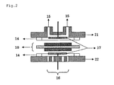
- Fig. 2 shows one example of a structure of the fuel cell.
- the fuel cell has an MEA 10, a pair of collectors 17 composed of a separator and gaskets 14.
- the collector 17 on the anode electrode side is provided with a supply and exhaust opening 15 on the anode electrode side; and the collector 17 on the cathode electrode side is provided with a supply and an exhaust opening 16 on the cathode electrode side.
- a gas fuel such as hydrogen and an alcohol (for example, methanol) or a liquid fuel such as an alcohol aqueous solution is supplied from the supply and exhaust opening 15 on the anode electrode side; and an oxidizing agent gas such as an oxygen gas and air is supplied from the supply and exhaust opening 16 from the cathode electrode side.
- the catalyst layer to be used in the membrane and electrode assembly 10 uses the ion exchangeable polymer particle dispersion liquid of the invention and is constituted of an active metal catalyst catalyst-carried conductive material, and if desired, it may contain a water repellent and a binder.
- a layer (conductive layer) composed of a catalyst-non-carried conductive material and optionally, a water repellent and a binder may be formed outside the catalyst layer.
- a catalyst having an active metal catalyst carried on a conductive material is used.
- any metal capable of promoting an oxidation reaction of hydrogen and a reduction reaction of oxygen is useful, and examples thereof include platinum, gold, silver, palladium, iridium, rhodium, ruthenium, iron, cobalt, nickel, chromium, tungsten, manganese, vanadium and alloys thereof.
- platinum is used in many cases.
- a particle size of the active metal catalyst to be used is usually in the range of from 2 to 10 nm.
- the particle size of the active metal catalyst to be used is preferably 2 nm or more.
- Activated polarization in a hydrogen-oxygen system fuel cell is greater for a cathode pole side (air pole side) compared with anode pole side (hydrogen pole side). This is because reaction at the cathode pole side (reduction of oxygen) is slower compared with that at the anode pole side.
- various platinum-based bimetallic catalysts such as Pt-Cr, Pt-Ni, Pt-Co, Pt-Cu, Pt-Fe can be used.
- Pt-Cr, Pt-Ni, Pt-Co, Pt-Cu, Pt-Fe platinum-based bimetallic catalysts
- suppression of catalyst poisoning by CO is important.
- platinum-based bimetals such as Pt-Ru, Pt-Fe, Pt-Ni, Pt-Co and Pt-Mo
- trimetallic catalyst such as Pt-Ru-Mo, Pt-Ru-W, Pt-Ru-Co, Pt-Ru-Fe, Pt-Ru-Ni, Pt-Ru-Cu, Pt-Ru-Sn and Pt-Ru-Au
- Pt-Ru-Mo platinum-based bimetals
- Pt-Ru-Ru-W platinum-based bimetals
- Pt-Ru-Co platinum-based bimetals
- Pt-Ru-Fe platinum-based bimetals
- Pt-Ni platinum-based bimetals
- Pt-Co platinum-based bimetals
- Pt-Ru-Mo platinum-based bimetals
- Pt-Ru-W platinum-based bimetals
- Pt-Ru-Co platinum-based bimetals
- Pt-Ru-Fe platinum-based bimetals
- Pt-Ni P
- any electron conductive substance is useful, and examples thereof include various metals and carbon materials.
- the carbon material include carbon blacks such as furnace black, channel black and acetylene black; active carbon; and graphite. These materials can be used singly or in admixture.
- acetylene black, Vulcan XC-72, ketjen black, carbon nanohorn (CNH) and carbon nanotube are preferably used.
- the functions of the catalyst layer are: (1) to transport the fuel to the active metal, (2) to provide a field for oxidation reaction (anode pole) and reduction reaction (cathode pole) of the fuel, (3) to transmit electrons generated by oxidation-reduction to the current collector, and (4) to transport protons generated by the reaction to the solid electrolyte.
- the catalyst layer In order to accomplish (1), the catalyst layer must be porous to allow the liquid and gas fuels to permeate deeply. (2) is borne by the aforementioned active metal catalyst, and (3) is borne by the also aforementioned carbon material. In order to fulfill the function of (4), the catalyst layer is mixed with a proton conductive material.
- the ionic polymer particle of the invention works as a proton conducting material of the catalyst layer.
- the ionic polymer particle is preferably a polymer containing at least one structural unit the same as in the electrolyte membrane, more preferably a polymer constituted of the same structural unit as in the polymer electrolyte membrane, and most preferably a polymer the same as in the polymer electrolyte membrane.
- the catalyst layer further contains a water repellent.
- a water repellent for example, fluorinated carbons and water-repellent fluorine-containing resins are preferable; and those having excellent heat resistance and oxidation resistance are especially preferable.
- the water repellent which can be used include polytetrafluoroethylene, a tetrafluoroethylene-perfluoroalkyl vinyl ether copolymer and a tetrafluoroethylene-hexafluoropropylene copolymer.
- the use amount of the active metal catalyst a range of from 0.03 to 10 mg/cm 2 is suitable from the viewpoints of cell output and economy.
- the amount of the conductive material for carrying the active metal catalyst is suitably from 1 to 10 times the mass of the active metal catalyst.
- the conductive layer is also called an electrode substrate, a transmission layer or a backing layer, has a collection function and plays a role for preventing deterioration of the gas transmission to be caused due to gathering of water.
- a material prepared by using carbon paper or a carbon cloth and treating it with polytetrafluoroethylene (PTFE) for the purpose of making it water-repellent can be used, too.
- Examples of a method for carrying the active metal catalyst include a heat reduction method, a sputtering method, a pulse laser deposition method and a vacuum vapor deposition method (see, for example, WO 2002/054514 ).
- a dispersion (catalyst layer coating solution) prepared by using the ion exchangeable polymer particle dispersion liquid of the invention and mixing with the active metal catalyst-carried conductive material is dispersed.
- solvent of the dispersion examples include heterocyclic compounds (for example, 3-methyl-2-oxazolidinone and N-methylpyrrolidone); cyclic ethers (for example, dioxane and tetrahydrofuran); chain ethers (for example, diethyl ether, ethylene glycol dialkyl ethers, propylene glycol dialkyl ethers, polyethylene glycol dialkyl ethers and polypropylene glycol dialkyl ethers); alcohols (for example, methanol, ethanol, isopropanol, ethylene glycol monoalkyl ethers, propylene glycol monoalkyl ethers, polyethylene glycol monoalkyl ethers and polypropylene glycol monoalkyl ethers); polyhydric alcohols (for example, ethylene glycol, propylene glycol, polyethylene glycol, polypropylene glycol and glycerin) ; nitrile compounds (for example, acetonitrile)
- mixing is carried out such that the ion exchangeable polymer particle in the ion exchangeable polymer particle dispersion liquid of the invention is contained in a proportion of 0.2 to 3 times the amount of the active metal catalyst in the active metal catalyst-carried conductive material in terms of a weight ratio.
- the dispersion may be carried out by stirring, and ultrasonic dispersion, a ball mill and the like may also be used.
- the resulting dispersion liquid may be coated by using a coating method such as a curtain coating, extrusion coating, roll coating, spin coating, dip coating, bar coating, spray coating, slide coating and print coating methods.
- a film may be formed by extrusion molding, or casting or coating of the above-described dispersion liquid.
- a support in this case is not particularly restricted, and preferable examples thereof include a glass substrate, a metal substrate, a polymer film, a reflection board and the like.
- the polymer film include a film of cellulose-based polymers such as triacetyl cellulose (TAC), ester-based polymers such as polyethylene terephthalate (PET) and polyethylene naphthalate (PEN), fluorine-containing polymers such as polytrifluoroethylene (PTFE), and polyimide.
- TAC triacetyl cellulose
- PET polyethylene terephthalate
- PEN polyethylene naphthalate
- fluorine-containing polymers such as polytrifluoroethylene (PTFE), and polyimide.
- the coating may be carried out according to a known system such as a curtain coating, extrusion coating, roll coating, spin coating, dip coating, bar coating, spray coating, slide coating and print coating methods.
- a conductive porous material carbon paper, carbon cloth
- a film-forming machine that uses rolls such as calendar rolls or cast rolls, or a T die, or press molding by a press machine may also be utilized. Further, a stretching process may be added to control the film thickness or improve film characteristics.
- a method in which an electrode catalyst having been formed in a paste shape as described above is directly sprayed to the solid electrolyte film with an ordinary sprayer to form the catalyst layer, can be also used. Control of the spray time and the spray volume makes formation of a uniform electrode catalyst layer possible.
- Drying temperature in the coating process relates to the drying speed, and can be selected in accordance with properties of the material. It is preferably -20°C to 150°C, more preferable 20°C to 120°C, and further preferably 50°C to 100°C. A shorter drying time is preferable from the viewpoint of productivity, however, a too short time tends to easily generate such defects as bubbles or surface irregularity. Therefore, drying time of 1 minute to 48 hours is preferable, 5 minutes to 10 hours is more preferable, and 10 minutes to 5 hours is further preferable. Control of humidity is also important, and relative humidity (RH) is preferably 25 to 100%, and more preferably 50 to 95%.
- RH relative humidity
- the coating liquid (dispersion liquid) in the coating process preferably contains a small amount of metal ions, and in particular, it contains a small amount of transition metal ions, especially an iron, nickel and cobalt ions.
- the content of transition metal ions is preferably 500 ppm or less, and more preferably 100 ppm or less. Therefore, solvents used in the aforementioned processes preferably contains these ions in a small amount, too.
- a surface treatment may be carried out after performing the coating process.
- surface treatment surface roughening, surface cutting, surface removing or surface coating may be performed, which may, in some cases, improve adherence with the solid electrolyte film or the porous conductive material.
- Thickness of the catalyst layer included in the MEA of the invention is preferably 5 to 200 ⁇ m, and particularly preferably 10 to 100 ⁇ m.
- the electrolyte membrane is assembled with the catalyst layer, the conductive layer and the like to prepare MEA.
- the preparation is not particularly limited, but known methods can be applied.
- the above-described hot press is preferably carried out under following conditions.
- the electrolyte membrane may be of a proton type having a sulfonic acid as a substituent, or of a salt type having a salt of sulfonic acid as described in JP-A-2004-165096 and JP-A-2005-190702 .
- the counter cation of a salt type sulfonic acid is preferably a mono- or di-valent cation, and more preferably a monovalent cation. Specifically, lithium ion, sodium ion, potassium ion or magnesium ion is preferable. Further, plural types may be employed from the group consisting of these cations and a proton. Sodium salt and potassium salt are even more preferable.
- the solid electrolyte In order to use it for a fuel cell, the solid electrolyte must have proton conductivity. For the purpose, by contacting the solid electrolyte with an acid, a salt substitution percentage thereof is reduced to 99% or less of that before the contact. Contact with an acid after joining the electrode catalyst and the polymer electrolyte film can recover lowering in moisture content and ion conductivity of the film caused by thermal history that is given during the electrode joining.
- an acidic aqueous solution such as hydrochloric acid, sulfuric acid, nitric acid and an organic sulfonic acid
- the immersion method is preferable because it is simple and easy.
- a method of using a mineral acid such as hydrochloric acid, sulfuric acid and nitric acid is also preferable.
- a concentration of the acidic aqueous solution relies upon a state of lowering of ionic conductivity, an immersion temperature, an immersion time, etc.
- an acidic aqueous solution of from 0.0001 to 5 N can be favorably used, with the range of from 0.1 to 2 N being especially preferable.
- the immersion temperature when the immersion temperature is room temperature, the conversion can be thoroughly achieved.
- the acidic aqueous solution may be heated.
- the temperature is preferably in the range of from 30 to 100°C, and more preferably in the range of from 50 to 95°C.
- the immersion time relies upon the concentration and immersion temperature of the acidic aqueous solution, and the immersion can be favorably carried out for from about 10 minutes to 24 hours. From the viewpoint of productivity, the immersion time is preferably not more than 6 hours, and especially preferably not more than 4 hours.
- the amount of impurities contained in this acidic aqueous solution is preferably not more than 1 % by weight, and more preferably not more than 0.1% by weight.
- Such method may be also employed that a proton moving in the inside of the film functions as an acid upon operating a fuel cell to wash out a substituted cation, thereby allowing the film to exert a higher ion conductivity.
- a method for producing the fuel cell using the electrolyte membrane produced by such method is described.
- the polymer electrolyte fuel cell is configured by stacking a plural number of single cells via a cooling plate etc. , wherein the single cell is that a fuel distribution plate and an oxidant distribution plate as a groove-provided collector for forming a fuel channel and an oxidant channel are disposed outside the thus formed assembly of an electrolyte membrane as formed as above-described and an electrode.
- the collector (bipolar plate) is a graphite-made or metal-made channel forming material-cum-collector having a gas channel on the surface thereof, etc.
- a fuel cell stack can be prepared by inserting an assembly of an electrolyte membrane and a gas diffusion electrode between such collectors and piling a plural number of the resulting materials.
- single cell voltage of a fuel cell is 1.2 V or less, therefore, single cells are used in series stacking in accordance with necessary voltage required from load.
- the stacking method there are 2 usable methods, that is, “planar stacking” wherein single cells are aligned on a plane and “bipolar stacking” wherein single cells are stacked via a separator having fuel paths formed on both sides thereof.
- the former is suitable for a compact fuel cell, because the cathode electrode side (air pole) is exposed on the surface, thereby making it easy to take in air and possible to form a thin type stacking.
- a method is proposed in which, while applying MEMS technology, microfabrication is given to a silicon wafer to form a stacking.
- a higher operating temperature of a fuel cell is preferable, because catalyst activity enhances. But, ordinarily, it is operated at 50°C to 120°C, at which water content is easily controlled.
- a higher supply pressure of oxygen and hydrogen may be preferable because a fuel cell output increases, since probability of their contact through film breakage or the like also increases, the pressure is preferably controlled within a suitable range such as 1 to 3 atmospheric pressures.
- examples of an anode fuel include hydrogen, alcohols (for example, methanol, isopropanol and ethylene glycol), ethers (for example, dimethyl ether, dimethoxymethane and trimethoxymethane), forming acid, boron hydride complexes and ascorbic acid.
- examples of a cathode fuel include oxygen (also including oxygen in the air) and hydrogen peroxide.
- the method for supplying the foregoing anode fuel and cathode fuel into the respective catalyst layers includes two methods of (1) a method of forcedly circulating the fuel using an auxiliary machinery such as a pump (active type); and (2) a method not using an auxiliary machinery (for example, in case of a liquid, a capillary phenomenon or free drop; and in case of a gas, a passive type in which the catalyst layer is exposed to the air and the fuel is supplied). These methods can also be combined. While the former has advantages such as realization of a high output by pressurization and humidity control of a reaction gas or the like, it involves a drawback that it is difficult to achieve downsizing. While the latter has an advantage that downsizing is possible, it involves a drawback that a high output is hardly obtainable.
- the hydrogen type fuel cell is expected as an energy source for various hot water-supplying and power generating apparatuses for home use, source of power for transport apparatuses, and an energy source for portable electronic devices, while utilizing the advantage of generating a high output.
- the hot water-supplying and power generating apparatus to which it can be preferably applied includes home-use, collective housing-use and hospital-use apparatuses;
- the transport apparatus includes the automobile and marine vessel;
- the portable device includes the cellular phone, mobile notebook computer and electronic still camera and the like.
- the suitably applicable portable device include a portable generator, outdoor lighting device and the like.
- a sulfonated polysulfone electrolyte was obtained in the same manner as in the preparation of a solid electrolyte of Example 1 of JP-A-2006-344578 .
- a sulfonated polysulfone electrolyte was obtained in the same manner as in the preparation of a solid electrolyte of Example 3 of JP-A-2006-344578 .
- a poor solvent and an ionic polymer solution were continuously mixed to obtain an ionic polymer particle dispersion liquid.
- a solution obtained by dissolving the ionic polymer (P-1 or P-2) which is poorly soluble in water in N-methylpyrrolidone as a good solvent was used as the ionic polymer solution. Water was used as the poor solvent.
- the ionic polymer solution having an ionic polymer dissolved therein was supplied from an ionic polymer solution tank, and the poor solvent was supplied from a poor solvent tank. These were supplied at the same time, and the respective supply flow rates are shown in Table 1.
- the ionic polymer solution was supplied at a temperature of 45°C
- the poor solvent was supplied at a temperature of 25°C.
- ionic polymer particle dispersion liquids as shown in Table 1 were obtained.
- the obtained ionic polymer particle dispersion liquids were each measured with respect to a volume average particle size by using a dynamic light scattering particle size distribution analyzer (LB-550 (a trade name) , manufactured by Horiba, Ltd.). The obtained results are also shown in Table 1.
- Example 1 Example 2
- Example 3 Example 4
- Example 5 Example 6 Ionic polymer P-1 P-1 P-1 P-1 P-2 P-2 Concentration of ionic polymer solution (% by mass) 3.0 3.0 3.0 5.0 3.0 5.0 Flow rate of good solvent (mL/min) 50 21 10 21 21 21 Flow rate of poor solvent (mL/min) 50 50 50 50 50 Particle size ( ⁇ m) 0.50 0.22 0.12 0.33 0.18 0.27
- P-1 was dissolved in N-methylpyrrolidone as the good solvent in a concentration of 1.5 % by mass. This was measured by the foregoing dynamic light scattering particle size distribution analyzer. However, a polymer particle dispersion was not observed.
- Example 2 After mixing 2 g of platinum-carried carbon (having 50 % by mass of platinum carried on Vulcan XC72) and 0.1 g of a polytetrafluoroethylene powder, 40 mL of the ionic polymer particle dispersion liquid as prepared in Example 2 was added, and the mixture was dispersed by an ultrasonic disperser for 30 minutes, thereby preparing a paste for catalyst layer.
- the obtained paste for catalyst layer was coated on a support having a reinforcing material incorporated therein (a polytetrafluoroethylene film (manufactured by Saint-Gobain K.K.)), dried and then punched out in a prescribed size, thereby preparing a catalyst layer.
- the coating amount was about 0.2 mg/cm 2 in terms of a carrying amount of platinum.
- the ionic conductivity was measured by employing a four-terminal alternating current method in conformity with Journal of the Electrochemical Society, Vol. 143, No. 4, pages 1254 to 1259 (1996 ).
- the electrolyte membrane M-1 was cut out in a length of 2 cm and a width of 1 cm; four platinum wires were fixed at intervals of 5 mm to a PTFE plate; the electrolyte membrane M-1 was placed thereon; and a tetrafluoroethylene resin (PTFE) was further stacked thereon, followed by screw fixing to build up a test cell.
- PTFE tetrafluoroethylene resin
- the electrolyte membrane M-1 for the measurement was previously protonated using a sulfuric acid aqueous solution.
- the above-obtained catalyst layer was stuck on the both surfaces of the electrolyte membrane M-1 such that the coating surface of the paste for catalyst layer came into contact with the electrolyte membrane and subjected to thermal contact bonding, and after lowering the temperature while applying a pressure, the support having a reinforcing material incorporated therein was separated.
- the salt in the electrolyte membrane M-1 was protonated using a sulfuric acid aqueous solution.
- E-TEK's gas diffusion electrode (conductive layer) having been cut into the same size as the electrode was stacked on the above-obtained membrane and electrode assembly and set in a standard fuel cell test cell, manufactured by ElectroChem Incorporated, and the test cell was connected to a fuel cell evaluation system (As-510, manufactured by NF Corporation).
- a humidified hydrogen gas was flown on the anode electrode side; a humidified imitation air was flown on the cathode electrode side; and the system was operated until the voltage became stable. Thereafter, a load was applied between the anode electrode and the cathode electrode to record current-voltage properties.
- a membrane and electrode assembly was prepared in the same manner as in Example 7, except that 80 mL of the ionic polymer particle dispersion liquid as prepared in Example 3 was added in place of the addition of 40 mL of the ionic polymer particle dispersion liquid as prepared in Example 2 which was used in the catalyst layer as prepared in Example 7.
- a membrane and electrode assembly was prepared in the same manner as in Example 7, except that 80 mL of the ionic polymer particle dispersion liquid as prepared in Comparative Example 1 was added in place of the addition of 40 mL of the ionic polymer particle dispersion liquid as prepared in Example 2 which was used in the catalyst layer as prepared in Example 7.
- a membrane and electrode assembly was prepared in the same manner as in Example 7, except that 15 mL of a NAFION (a registered trademark) solution (5 % by weight solution, manufactured by Aldrich) was added in place of the addition of 40 mL of the ionic polymer particle dispersion liquid in Example 2 which was used in the catalyst layer in Example 7.
- Table 2 Example 7
- Example 8 Comparative Example 2 Comparative Example 3
- Ionic polymer P-1 P-1 P-1 NAFION State Dispersed state Dispersed state Dissolved Dispersed state Maximum output (W/cm 2 ) 0.63 0.65 0.21 0.55 Output in high current density region (W/cm 2 ) 0.52 0.55 0 0.42
- the electrode using the ionic polymer particle dispersion liquid of the invention is excellent in adhesion to an electrolyte membrane and enables one to prepare a polymer electrolyte fuel cell having an excellent power generating performance.
- the fuel cell using the electrode of the invention has a possibility such that it is utilized for a cogeneration system, a fuel cell automobile, etc.
Landscapes
- Chemical & Material Sciences (AREA)
- Health & Medical Sciences (AREA)
- Chemical Kinetics & Catalysis (AREA)
- Medicinal Chemistry (AREA)
- Polymers & Plastics (AREA)
- Organic Chemistry (AREA)
- Dispersion Chemistry (AREA)
- Fuel Cell (AREA)
- Compositions Of Macromolecular Compounds (AREA)
- Inert Electrodes (AREA)
- Processes Of Treating Macromolecular Substances (AREA)
Abstract
Description
- The present invention relates to an ionic polymer particle dispersion liquid and to a method for producing the same. In particular, the invention relates to an ionic polymer particle dispersion liquid to be used for an electrode for polymer electrolyte fuel cell.
- In recent years, in cooperation with social needs and trend against the backdrop of an energy or environmental issue, a fuel cell capable of working even at normal temperature and of yielding a high output density is noticed as a power source for electric automobile or a stationary power source. The fuel cell is a clean power generating system in which a product by the electrode reaction is water in principle and which does not substantially adversely affect the global environment. The fuel cell includes a polymer electrolyte fuel cell (PEFC), a phosphoric acid fuel cell (PAFC), an alkaline fuel cell (AFC), a solid oxide fuel cell (SOFC) and a molten carbonate fuel cell (MCFC). Of these, the polymer electrolyte fuel cell is expected as a power source for electric automobile because it works at a relatively low temperature and yields a high output density.
- In general, the polymer electrolyte fuel cell has a structure in which a membrane and electrode assembly (hereinafter also referred to as "MEA") is interposed between separators. For example, MEA is composed such that an electrolyte membrane is interposed between a pair of a catalyst layer and a conductive layer (gas diffusion layer).
- The catalyst layer is a porous layer formed of a mixture of an electrolyte and a conductive material on which an active metal catalyst is carried. Also, as a conductive layer, a layer by forming a carbon water-repellent layer comprising a carbon particle, a water repellent and the like on the surface of a gas diffusion substrate such as carbon cloth is used.
- In the polymer electrolyte fuel cell, an electrochemical reaction proceeds in the following manner. First of all, hydrogen contained in a fuel gas which is supplied into the catalyst layer on the anode electrode side is oxidized by the active metal catalyst to form a proton and an electron as expressed in the following expression (1). Next, the formed proton goes through a proton conducting material contained in the catalyst layer on the anode electrode side and further through the electrolyte membrane coming into contact with the catalyst layer on the anode electrode side to reach the catalyst layer on the cathode electrode side. Also, the electron formed in the catalyst layer on the anode electrode side goes through a conductive material constituting the catalyst layer on the anode electrode side and further through the conductive layer contacting with the side different from the polymer electrolyte membrane of the catalyst layer on the anode electrode side and passes through a separator and an external circuit to reach the catalyst layer on the cathode electrode side. The proton and the electron, both of which have reached the catalyst layer on the cathode electrode side react with oxygen contained in an oxidizing agent gas which is supplied on the cathode electrode side by the active metal catalyst to form water as expressed in the following expression (2). The fuel cell makes it possible to take out electricity to the outside through the foregoing electrochemical reaction. Catalyst layer on the anode electrode side: H2 → 2H+ + 2e- (1) Catalyst layer on the cathode electrode side: 1/2O2 + 2H+ + 2e- → H2O (2)
- For that reason, the electrolyte membrane is required to have high proton conductivity, a function as a separator interposed between the electrodes and the like.
- The manufacturing process of a polymer electrolyte fuel cell is described in, for example,
JP-A-5-135785 -
JP-A-2003-55568 JP-A-2004-35864 JP-A-2004-75979 -
JP-A-2004-256711 - A problem of the invention is to overcome such inconveniences and to provide an ionic polymer particle dispersion liquid utilizable for a material of a catalyst layer and a method for producing the same.
- Under such circumstances, the present inventor made further investigations on the following points.
- A perfluoroalkylene sulfonic acid polymer (for example, NAFION (a registered trademark), manufactured by DuPont) which has hitherto been widely used as an electrolyte membrane in a membrane and electrode assembly has excellent proton conductivity because of being made by sulfonation and chemical resistance as a fluorocarbon resin, but it is expensive. Therefore, the present inventor also made investigations for the purpose of avoiding such a problem.
- Then, the present inventor made investigations for the purpose of forming a membrane and electrode assembly using, for example, a sulfonated product of a hydrocarbon based polymer compound which does not contain fluorine in a molecular structure thereof or which is reduced in an amount of fluorine in a molecular structure thereof, as an inexpensive electrolyte membrane in place of the perfluoroalkylene sulfonic acid polymer. This point has hitherto been studied, as a hydrocarbon based polymer, a polymer with a main chain in which plural benzene rings such as polyether ether ketone and benzimidazole are bonded via a divalent organic group or directly is known. Also, as a hydrocarbon based polymer,
U. S. Patent No. 5, 403, 675 describes a rigid polyphenylene compound. - However, the present inventor has found out that when an electrolyte membrane, especially an electrolyte membrane composed of a hydrocarbon based polymer, is interposed between catalyst layers and integrated, sufficient adhesion between the electrolyte membrane and the catalyst layers becomes poor. Also, in a membrane and electrode assembly with low adhesion between an electrolyte membrane and a catalyst layer, since the transfer of a proton between the electrolyte membrane and the catalyst layer is hindered, a sufficient power generating performance is not obtainable.
- As a result of investigations made by the present inventor, it was found that the reason why the adhesion is low resides in that even when the foregoing hydrocarbon based polymer is used as a material of the electrolyte membrane, the perfluoroalkylene sulfonic acid polymer is used in the catalyst layer. This is because the foregoing hydrocarbon based polymer cannot be dispersed in a solvent as the perfluoroalkylene sulfonic acid polymer so that it cannot be incorporated into the catalyst layer.
- Under these circumstances, the present inventor made extensive and intensive investigations. As a result, it has been found that the foregoing problems can be solved by the following measures.
- (1) An ionic polymer particle dispersion liquid prepared by continuously mixing a poor solvent in which an ionic polymer is poorly soluble, and an ionic polymer solution comprising the ionic polymer dissolved in a good solvent having miscibility with the poor solvent and having readily-solubility to the ionic polymer, to form an ionic polymer particle, the ionic polymer being an aromatic hydrocarbon based polymer.
- (2) The ionic polymer particle dispersion liquid as set forth in (1), wherein the aromatic hydrocarbon based polymer is a sulfoalkylated aromatic hydrocarbon based polymer.
- (3) The ionic polymer particle dispersion liquid as set forth in (1) or (2), wherein the ionic polymer particle has a volume average particle size of from 1 nm to 200 nm.
- (4) The ionic polymer particle dispersion liquid as set forth in any one of (1) to (3), wherein an addition flow rate of the poor solvent to an addition flow rate of the ionic polymer solution is 3 or more in terms of a volume flow rate ratio.
- (5) The ionic polymer particle dispersion liquid as set forth in any one of (1) to (4), wherein the ionic polymer has a sulfonic group.
- (6) An electrode for fuel cell using the polymer particle dispersion liquid as set forth in any one of (1) to (5).
- (7) A membrane and electrode assembly comprising a pair of electrodes and an electrolyte membrane provided between the electrodes, the electrodes being the electrode for fuel cell as set forth in (6).
- (8) A fuel cell using the membrane and electrode assembly as set forth in (7).
- (9) A method for producing an ionic polymer particle dispersion liquid comprising continuously mixing a poor solvent in which an ionic polymer is poorly soluble, and an ionic polymer solution comprising the ionic polymer dissolved in a good solvent having miscibility with the poor solvent and having readily-solubility to the ionic polymer, to form an ionic polymer particle, the ionic polymer being an aromatic hydrocarbon based polymer.
- (10) The method for producing an ionic polymer particle dispersion liquid as set forth in (9), further comprising dispersing for stabilization the ionic polymer particle.
- (11) The method for producing an ionic polymer particle dispersion liquid as set forth in (9) or (10), further comprising concentrating the ionic polymer particle dispersion liquid.
- By employing an electrode using the ionic polymer particle dispersion liquid of the invention, it has made possible to prepare a fuel cell which is excellent in the maximum output.
-
-
Fig. 1 is a diagrammatic cross-sectional view showing one example of a configuration of a membrane and electrode assembly. -
Fig. 2 is a diagrammatic cross-sectional view showing one example of a structure of a fuel cell. -
Fig. 3 shows one example of a preparation method of an ionic polymer fine particle dispersion. - The contents of the invention are hereunder described in detail. In this specification, numerical value ranges expressed by the term "to" mean that the numerical values described before and after it are included as a lower limit and an upper limit, respectively.
- First of all, one example of a preparation method of an ionic polymer particle dispersion liquid of the invention is described with reference to a drawing (
Fig. 3 ). - The explanation of constitutional elements as described below is one example (representative example) of embodiments of the invention, but it should not be construed that the invention is limited to these contents.
- The preparation method of the ionic polymer particle dispersion liquid of the invention is a production method utilizing a so-called poor solvent precipitation method of a continuous system in which a poor solvent in which an ionic polymer is poorly soluble and an ionic polymer solution comprising the ionic polymer dissolved in a good solvent having miscibility with the poor solvent and having readily-solubility to the ionic polymer, are continuously mixed to form an ionic polymer particle. The terms "continuously mixed" as referred to herein refer to a state in which the poor solvent and the ionic polymer solution are mixed in a state wherein the both are fluidized and new mixing continuously occurs with a lapse of time.
- In the invention, the ionic polymer particle is prepared in a mixing and precipitation step of continuously mixing a poor solvent and an ionic polymer solution to form an ionic polymer particle dispersion liquid. One preferred embodiment of the invention is hereunder specifically described with reference to the drawing.
- That is, as illustrated in
Fig. 3 , in general, a mixing and precipitation step (A) of continuously mixing a poor solvent and an ionic polymer solution to form an ionic polymer particle dispersion liquid is included. Furthermore, it is preferable that a dispersion and stabilization step (B) of dispersing for stabilization an ionic polymer particle in the ionic polymer particle dispersion liquid or a concentration step (C) of concentrating the ionic polymer particle dispersion is included. The configuration of an instrument to be used in the invention is described along with the contents of the foregoing respective steps. - While illustration is omitted, in the foregoing mixing and precipitation step (A), in general, an ionic polymer solution comprising an ionic polymer is supplied from an ionic polymer solution tank, and a poor solvent is supplied from a poor solvent tank. In that case, these ionic polymer solution and poor solvent are each supplied after adjusting the temperature to a prescribed temperature with a liquid feed pump and a heat exchanger. Though the temperature suitable for the precipitation of the ionic polymer particle varies depending upon the objective ionic polymer, it is usually from 0 to 90°C, and preferably from 0 to 50°C. More specifically, the temperature of the ionic polymer solution is from 10 to 50°C, and the temperature of the poor solvent is from 0 to 40°C.
- In supplying the ionic polymer solution and the poor solvent into the mixing and precipitation step (A), the temperature control of the ionic polymer solution and the poor solvent may be carried out by providing each of the ionic polymer solution tank and the poor solvent tank with a temperature control measure in place of the foregoing heat exchanger.
- In the invention, the ionic polymer is mainly objective to one which is poorly soluble in water. That is, in that case, the poor solvent against the ionic polymer is water, and the good solvent against the ionic polymer is an organic solvent. However, in the invention, a water-soluble ionic polymer can not be applied, and a combination of the ionic polymer and a solvent is of importance. For example, in the case where an aromatic hydrocarbon based polymer is used as the ionic polymer, the good solvent is preferably dimethylacetamide, and the poor solvent is preferably water.
- The ionic polymer which is poorly soluble in water as referred to in the invention refers to one which usually has a solubility in water of not more than 10 mg/mL, especially in water at 20°C. In the present invention, the solubility in water at 20°C of the ionic polymer which is poorly soluble in water is preferably not more than 5 mg/mL, and more preferably not more than 1 mg/mL. It is preferable that the solubility is lower because when water is used as the poor solvent, in particular, a finer particle can be formed more advantageously.
- As to the ionic polymer to be used in the invention, it is preferable to use an aromatic hydrocarbon based polymer; and it is more preferable to use a sulfoalkylated aromatic hydrocarbon based polymer having an aromatic ring in a main chain thereof and having a sulfoalkyl group represented by the following formula (1) into a side chain thereof. Specific examples thereof include engineering plastics such as polyetheretherketone (PEEK) having a structural unit represented by the following formula (2) which is developed by ICI, UK in 1977; semi-crystalline polyaryletherketone (PAEK) which is developed by BASF, Germany; polyetherketone (PEK) having a structural unit represented by the following formula (3) which is sold by Sumitomo Chemical Co. , Ltd. , etc. ; polyketone (PK) which is sold by Teijin Amoco Engineering Plastic Ltd.; polyethersulfone (PES) having a structural unit represented by the following formula (4) which is sold by Sumitomo Chemical Co., Ltd., Teijin Amoco Engineering Plastics Ltd., Mitsui Chemicals Inc., etc.; polysulfone (PSU) having a structural unit represented by the following formula (5) which is sold by Solvay Advanced Polymers K.K.; linear or crosslinked polyphenylene sulfide (PPS) having a structural unit represented by the following formula (6) which is sold by Toray Industries, Inc. , Dai Nippon Chemical Industries Inc. , Toopren K.K., Idemitsu petrochemical Co., Ltd., Kureha Corporation, etc.; and denatured polyphenylene ether (PPE) having a structural unit represented by the following formula (7) which is sold by Asahi Kasei Corporation, GE Plastics Japan Ltd., Mitsubishi Engineering-Plastics Corporation and Sumitomo Chemical Co., Ltd.; or aromatic hydrocarbon based polymers having a sulfoalkyl group represented by the following formula (1) introduced into a side chain of a polymer alloy thereof. Of these, from the viewpoint of resistance to oxidative deterioration of the main chain, sulfoalkylated PEEK, PEAK, PEK, PK, PPS, PES and PSU are preferable.


- In the formula (7), R represents a lower alkyl group such as a methyl group and an ethyl group; or a phenyl group.
- A sulfonic acid type polystyrene-graft-ethylene tetrafluoroethylene copolymer (ETFE) constituted of a main chain prepared by copolymerization of a fluorocarbon based vinyl monomer and a hydrocarbon based vinyl monomer and a sulfonic group-containing hydrocarbon based side chain as disclosed in
JP-A-9-102322 JP-A-9-102322 U.S. Patent No. 4,012,303 andU.S. Patent No. 4,605,685 ; and the like can also be used. - An ion exchange group equivalent weight of the ionic polymer to be used in the invention is preferably from 250 to 2,500 g/mole, more preferably from 300 to 1,500 g/mole, and further preferably from 350 to 1,000 g/mole. When the ion exchange group equivalent weight is not more than 2, 500 g/mole, the output performance tends to be enhanced, whereas when it is 250 g/mole or more, the waterproof properties of the polymer tend to be enhanced, and therefore, such range is preferable.
- Here, the poor solvent in which the ionic polymer in the invention is poorly soluble refers to one having, for example, a solubility of ionic polymer of not more than 10 mg/mL.
- The poor solvent may be used singly or in admixture of two or more kinds thereof. The poor solvent to be used in the invention is preferably water.
- The good solvent is not particularly limited so far as it is a solvent capable of dissolving the ionic polymer therein and miscible with the poor solvent. A mixed solvent of two or more kinds of good solvents may be used.
- As the good solvent to be used in the invention, an organic solvent which can be easily removed from the ionic polymer particle dispersion liquid is preferable. Examples of such solvents include methanol, ethanol, isopropyl alcohol, 1-butanol, n-methylpyrrolidone, acetone, tetrahydrofuran, dimethylformamide, ethylenediamine, acetonitrile, methyl ethyl ketone, dimethyl sulfoxide, dichloromethane and dimethylacetamide.
- In the invention, as the good solvent which is miscible with the poor solvent and is readily-solubility to the ionic polymer, a solvent which is co-soluble with the poor solvent, namely a solvent which in mixing with the poor solvent, is not separated into liquid-liquid two phases at a mixing temperature and in a mixing proportion, is preferable. A solubility of the ionic polymer in the good solvent may be 10 mg/mL or more and is preferably 20 mg/mL or more. Though its upper limit is not particularly limited, it is about 200 mg/mL. A concentration of the ionic polymer in the ionic polymer solution may be a concentration not exceeding a saturated solubility at room temperature and is preferably from 50 to 100 % by mass, and more preferably from 70 to 90 % by mass of the solubility.
- Here, in continuously mixing with the poor solvent, a flow rate of the good solvent in which the ionic polymer is dissolved is preferably from 0.1 to 20,000 mL/min, and more preferably from 0.2 to 10,000 mL/min.
- On the other hand, in continuously mixing with the good solvent, a flow rate of the poor solvent is preferably from 1 to 50, 000 mL/min, and more preferably from 2 to 50, 000 mL/min.
- For example, in order to contain an ionic polymer particle of a sub-micron order of from 1 to 200 nm, in mixing the poor solvent and the ionic polymer solution, a volume flow rate ratio of the poor solvent to the good solvent is preferably set up at from 1/1 to 100/1, preferably set up at from 5/1 to 100/l, and further preferably set up at from 10/1 to 100/1. Furthermore, in order to obtain an ionic polymer particle dispersion liquid having a smaller particle size and having excellent dispersion stability by mixing the poor solvent and the ionic polymer solution, it is preferable to contain a dispersion stabilizer in the poor solvent or the ionic polymer solution.
- In the mixing and precipitation step (A), an ionic polymer particle dispersion liquid is formed by mixing the poor solvent and the ionic polymer solution. In the mixing and precipitation step (A), in order to obtain an ionic polymer particle dispersion liquid comprising a smaller particle size and having excellent dispersion stability, one or two or more kinds of dispersion stabilizers may be added in the ionic polymer solution or the poor solvent or both the ionic polymer solution and the poor solvent.
- The selection of the dispersion stabilizer varies depending upon the kinds of the ionic polymer and the good solvent. In general, the dispersion stabilizer is selected among nonionic, anionic or cationic surfactants, polymers, phospholipids and the like. Examples of the stabilizer which is especially preferable include a polyoxyethylene sorbitan fatty acid ester (a trade name: TWEEN), a sucrose fatty acid ester, a sorbitan fatty acid ester (a trade name: SPAN), a polyoxyethylene fatty acid ether, an aero sol (AOT), sodium lauryl sulfate, sodium deoxycholate, polyvinylpyrrolidone, polyvinyl alcohol, polyoxyethylene polyoxypropylene glycol (a trade name: PLURONIC), polyethylene glycol, polyoxyethylene castor oil, hydroxypropyl cellulose, dextran, gelatin, casein and lecithin.
- A concentration of the stabilizer is preferably set up such that a weight ratio thereof to the ionic polymer in the ionic polymer particle dispersion liquid to be formed is in the range of from 0.01 to 10.
- As described previously, in general, as to the volume flow rate ratio between the poor solvent and the ionic polymer solution in the mixing and precipitation step (A), the poor solvent is overwhelmingly large. Therefore, when the temperature of the poor solvent is controlled by the foregoing heat exchanger or temperature control measure of the tank, the temperature of the obtained ionic polymer particle dispersion liquid becomes substantially equal to the temperature of the poor solvent. Accordingly, the temperature of the poor solvent may be a temperature suitable for the precipitation of the ionic polymer particle. On the other hand, the temperature of the ionic polymer solution may be set up at the same temperature as that of the poor solvent or may be set up at a temperature at which there is no anxiety for the precipitation of a particle within a conduit prior to the introduction into the mixing and precipitation step (A).
- The ionic polymer particle dispersion liquid obtained in the foregoing mixing and precipitation step (A), namely a suspension in which the precipitated ionic polymer is dispersed in the solvent may be further dispersed and stabilized by immediately supplying it into a dispersion and stabilization step (B), if desired. In the dispersion and stabilization step (B), the particle size can be made smaller by applying a wet pulverization method which does not use a pulverization medium (for example, a steel ball for impact pulverization) and pulverizing and dispersing the ionic polymer particle in the ionic polymer particle dispersion liquid. Examples of the wet pulverization method which does not use a pulverization medium include a method in which coagulated particles are broken and pulverized by means of kinetic energy of fluid and impact energy due to cavitation by using an ultrasonic homogenizer, a high-pressure homogenizer (for example, homogenizers known as MICROFLUIDIZER (a trade name, manufactured by MFI Corporation, U.S.A.), ULTIMIZER (a trade name, manufactured by Sugino Machine Limited) and NANO-MIZER (a trade name, manufactured by Yoshida Kikai Co., Ltd.), respectively), a piston-gap homogenizer (for example, a homogenizer, manufactured by APV Gaulin), etc.
- If desired, the thus obtained ionic polymer particle dispersion liquid can be subjected to concentration or removal of the good solvent by immediately supplying into a concentration step (C). In adjusting the concentration of a solid, the poor solvent and the good solvent can be partially removed by utilizing a method known in the technical field such as distillation and membrane separation. In particular, in the case where the concentration of a solid is adjusted by an operation such as distillation, because there is a possibility that the particles in the suspension are coagulated, dispersion and stabilization may be again carried out.
- According to a preferred embodiment of the method for producing an ionic polymer particle of the invention, the ionic polymer solution can be rapidly and uniformly dispersed. As a result, an ionic polymer particle dispersion liquid having a volume average particle size of, for example, from 1 nm to 1 µm, and preferably from 1 to 200 nm can be obtained.
- The volume average particle size can be simply measured by a dynamic light scattering particle size distribution analyzer.
- The ionic polymer particle distribution of the invention can be used by, for example, adding in a catalyst layer of a membrane and electrode assembly which a fuel cell possesses. Preferred examples of an electrode for fuel cell, a membrane and electrode assembly and a fuel cell using the ionic polymer particle dispersion liquid of the invention are hereunder described.
- Membranes prepared by fabricating a known electrolyte in a membrane form and known electrolyte membranes can be widely employed as the electrolyte membrane to be used in the invention.
- Above all, fluorocarbon polymers are excellent in chemical stability so that they can be preferably used. Specific examples thereof include perfluorosulfonic acid membranes having high proton conductivity, which are known as trade names including NAFION (a registered trademark, manufactured by DuPont), ACIPLEX (a registered trademark, manufactured by Asahi Kasei Corporation) and FLEMION (a registered trademark, manufactured by Asahi Glass Co. , Ltd.).
- In the invention, for example, a sulfoalkylated aromatic hydrocarbon based polymer having an aromatic ring in a main chain thereof can be used as the electrolyte. In particular, it is preferable that a sulfoalkylated aromatic hydrocarbon based polymer having a sulfoalkyl group represented by the following formula (1) introduced into a side chain thereof is used as the electrolyte.
- Specific examples of the sulfoalkylated aromatic hydrocarbon based polymer include engineering plastics such as polyetheretherketone (PEEK) having a structural unit represented by the following formula (2) which is developed by ICI, UK in 1977; semi-crystalline polyaryletherketone (PAEK) which is developed by BASF, Germany; polyetherketone (PEK) having a structural unit represented by the following formula (3) which is sold by Sumitomo Chemical Co., Ltd., etc.; polyketone (PK) which is sold by Teijin Amoco Engineering Plastic Ltd.; polyethersulfone (PES) having a structural unit represented by the following formula (4) which is sold by Sumitomo Chemical Co., Ltd., Teij in Amoco Engineering Plastics Ltd., Mitsui Chemicals Inc., etc.; polysulfone (PSU) having a structural unit represented by the following formula (5) which is sold by Solvay Advanced Polymers K.K.; linear or crosslinked polyphenylene sulfide (PPS) having a structural unit represented by the following formula (6) which is sold by Toray Industries, Inc. , Dai Nippon Chemical Industries Inc. , Toopren K.K., Idemitsu petrochemical Co., Ltd., Kureha Corporation, etc.; and denatured polyphenylene ether (PPE) having a structural unit represented by the following formula (7) which is sold by Asahi Kasei Corporation, GE Plastics Japan Ltd., Mitsubishi Engineering-Plastics Corporation and Sumitomo Chemical Co., Ltd.; or aromatic hydrocarbon based polymers having a sulfoalkyl group represented by the following formula (1) introduced into a side chain of a polymer alloy thereof.
- Of these, from the viewpoint of resistance to oxidative deterioration of the main chain, PEEK, PEAK, PEK, PK, PPS, PES and PSU are preferable.


- In the formula (7), R represents a lower alkyl group such as a methyl group and an ethyl group; or a phenyl group.
- A sulfonic acid type polystyrene-graft-ethylene tetrafluoroethylene copolymer (ETFE) constituted of a main chain prepared by copolymerization of a fluorocarbon based vinyl monomer and a hydrocarbon based vinyl monomer and a sulfonic group-containing hydrocarbon based side chain as disclosed in
JP-A-9-102322 JP-A-9-102322 U.S. Patent No. 4,012,303 andU.S. Patent No. 4,605,685 ; and the like can also be used as an electrolyte membrane in the present invention. - An ion exchange group equivalent weight of the ionic polymer to be used in the invention is preferably from 250 to 2,500 g/mole, more preferably from 300 to 1,500 g/mole, and further preferably from 350 to 1,000 g/mole. When the ion exchange group equivalent weight is not more than 2, 500 g/mole, the output performance tends to be enhanced, whereas when it is 250 g/mole or more, the waterproof properties of the electrolyte tend to be enhanced, and therefore, such range is preferable.
- The ion exchange group equivalent weight as referred to in the invention represents a molecular weight of a polymer as the electrolyte per unit mole of a functional group having ion exchange properties, and it is meant that the smaller the value is, the higher the content of the functional group having ion exchange properties is. The ion exchange group equivalent weight can be measured by 1H-NMR spectroscopy, elemental analysis, acid-base titration described in
JP-B-1-52866 - Though the fabrication method of the electrolyte membrane is not particularly limited, a method of achieving fabrication from a solution state (a solution casting method) , a method of achieving fabrication from a molten state (a melt pressing method or a melt extrusion method) and the like can be employed. Specifically, as to the former, the fabrication can be achieved by, for example, cast coating a solution containing an ion exchange polymer as the electrolyte on a glass plate and removing a solvent. The solvent to be used for the fabrication is not particularly limited so far as it is able to dissolve an ion exchange polymer as the electrolyte therein and be then removed. Examples of the solvent which can be favorably used include aprotic polar solvents such as N,N'-dimethylformamide, N,N'-dimethylacetamide, N-methyl-2-pyrrolidone and dimethyl sulfoxide; alkylene glycol monoalkyl ethers such as ethylene glycol monomethyl ether, ethylene glycol monoethyl ether, propylene glycol monomethyl ether and propylene glycol monoethyl ether; halogen based solvents such as dichloromethane and trichloroethane; and alcohols such as isopropyl alcohol and tert-butyl alcohol.
- Though a thickness of the electrolyte membrane to be used in the invention is not particularly limited, it is preferably from 10 to 300 µm, more preferably from 10 to 200 µm, and further preferably from 30 to 100 µm. When the thickness of the electrolyte membrane is 10 µm or more, the electrolyte membrane has a strength more suitable for practical use; and when it is not more than 300 µm, a reduction in the membrane resistance, namely an enhancement in the power generating performance tends to be enhanced, and therefore, such range is preferable. In the case of the solution casting method, the thickness of the electrolyte membrane can be controlled by regulating the concentration of the solution of the ion exchange polymer as the electrolyte or regulating the thickness for coating on a substrate. In the case of the fabrication from a molten state, the thickness of the electrolyte membrane can be controlled by stretching a film having a prescribed thickness as obtained by a melt pressing method, a melt extrusion method or the like in a prescribed stretch ratio.
- In producing the electrolyte membrane to be used in the invention, additives which are used for usual polymers, such as a plasticizer, a stabilizer and a release agent can be used within the range where the object of the invention is not hindered.
- To the solid electrolyte of the invention, according to need, an oxidation inhibitor, a fiber, a fine particle, a water-absorbing agent, a plasticizer, a compatibilizing agent or the like may be added in order to enhance film properties. The content of these additives is preferably in a range of 1 to 30% by mass relative to the total amount of the solid electrolyte.
- Preferable examples of the oxidation inhibitor include (hindered) phenol-based, mono- or di-valent sulfur-based, tri-or penta-phosphorous-based, benzophenone-based, benzotriazole-based, hindered amine-based, cyanoacrylate-based, salicylate-based, and oxalic acid anilide-based compounds. Specifically, compounds described in
JP-A-8-53614 JP-A-10-101873 JP-A-11-114430 JP-A-2003-151346 - Preferable examples of the fiber include perfluorocabon fiber, cellulose fiber, glass fiber, polyethylene fiber and the like. Specifically, fibers described in
JP-A-10-312815 JP-A-2000-231928 JP-A-2001-307545 JP-A-2003-317748 JP-A-2004-63430 JP-A-2004-107461 - Preferable examples of the fine particle include fine particles composed of silica, alumina, titanium oxide, zirconium oxide and the like. Specifically, those described in
JP-A-6-111834 JP-A-2003-178777 JP-A-2004-217921 - Preferable examples of the water-absorbing agent (hydrophilic material) include cross-linked polyacrylates, starch-acrylates, poval, polyacrylonitrile, carboxymethyl cellulose, polyvinylpyrrolidone, polyglycol dialkylether, polyglycol dialkylester, silica gel, synthesized zeolite, alumina gel, titania gel, zirconia gel, and yttria gel. Specifically, water-absorbing agents described in
JP-A-7-135003 JP-A-8-20716 JP-A-9-251857 - Preferable examples of the plasticizer include phosphoric acid ester-based compounds, phthalic acid ester-based compounds, aliphatic monobasic acid ester-based compounds, aliphatic dibasic acid ester-based compounds, dihydric alcohol ester-based compounds, oxyacid ester-based compounds, chlorinated paraffins, alkylnaphthalene-based compounds, sulfone alkylamide-based compounds, oligo ethers, cabonates, and aromatic nitriles. Specifically, those described in
JP-A-2003-197030 JP-A-2003-288916 JP-A-2003-317539 - Further, the solid electrolyte of the invention may be incorporated with various polymer compounds for the purpose of (1) enhancing mechanical strength of the film, or (2) enhancing acid concentration in the film.
- (1) For the purpose of enhancing mechanical strength, such polymer compound is suitable that has molecular weight of around 10,000 to 1,000,000 and good compatibility with the solid electrolyte of the invention. For example, perfluorinated polymer, polystyrene, polyethylene glycol, polyoxetane, poly(meth)acrylate, polyether ketone, polyether sulfone, and polymers of 2 or more of these are preferable, and preferable content is in a range of 1 to 30% by mass relative to the whole.
A compatibilizing agent has a boiling point or sublimation point of preferably 250°C or more, and more preferably 300°C or more. - (2) For the purpose of increasing acid concentration, such polymer compound is preferable that has a proton acid site such as perfluorocarbon sulfonic acid polymers as represented by NAFION (a registered trademark), poly(meth)acrylates having a phosphoric acid group in a side chain, or sulfonated heat resistant aromatic polymers such as sulfonated polyether ether ketone, sulfonated polyether sulfone, sulfonated polysulfone or sulfonated polybenzimidazole, which is preferably contained in a range of 1-30% by mass relative to the whole.
- As to properties of the electrolyte membrane to be used in the invention, those having the following various performances are preferable.
- An ionic conductivity is preferably 0.005 S/cm or more, and more preferably 0.01 S/cm or more at 25°C and 95 % RH.
- As to the strength, for example, a tensile strength is preferably 10 MPa or more, and more preferably 20 MPa or more.
- As to the electrolyte membrane to be used in the invention, one having stable water absorption and water content is preferable. It is preferable that the solubility of the electrolyte membrane to be used in invention is of a substantially negligible degree against alcohols, water and a mixed solvent thereof. It is preferable that when the electrolyte membrane to be used in the invention is dipped in the foregoing solvent, a loss in weight and a change in form are of a substantially negligible degree.
- In the case of forming a membrane, as to the ion conducting direction, it is preferable that a direction from the front surface toward the rear surface is higher than other directions. However, the ion conducting direction may be random.
- A heat resistant temperature of the electrolyte membrane to be used in the invention is preferably 200°C or higher, more preferably 250°C or higher, and further preferably 300°C or higher. For example, the heat resistant temperature can be defined as a time when it reaches a loss in weight of 5 % upon heating at a rate of 1°C/min. This loss in weight is calculated by eliminating a volatile matter such as water.
- Further, when the solid electrolyte of the invention is used for a fuel cell, an active metal catalyst that facilitates the oxidation-reduction reaction of an anode fuel and a cathode fuel may be added. As the result, fuels permeating into the solid electrolyte tend to be consumed in the solid electrolyte without reaching the other electrode, whereby crossover can be prevented. As active metal type to be used, an active metal catalyst as described after is suitable and, platinum or an alloy based on platinum is preferable.
- Next, the membrane and electrode assembly of the invention and the fuel cell using the membrane and electrode assembly are described.
-
Fig. 1 shows one example of a cross-sectional diagrammatic view of the membrane and electrode assembly of the invention.MEA 10 is provided with anelectrolyte membrane 11 and ananode electrode 12 and acathode electrode 13 interposing theelectrolyte membrane 11 therebetween and opposing to each other. - The
anode electrode 12 and thecathode electrode 13 are composed of, for example,conductive layers electrolyte membrane 11, a method in which the catalyst layers 12b and 13b are coated on theconductive layer sheets electrolyte membrane 11 by a hot pressing method (preferably at from 120 to 250°C and from 2 to 100 kg/cm2), or a method in which the catalyst layers 12b and 13b are coated on an appropriate support and subjected to contact bonding while transferring onto theelectrolyte membrane 11, followed by interposing between theconductive layers -
Fig. 2 shows one example of a structure of the fuel cell. The fuel cell has anMEA 10, a pair ofcollectors 17 composed of a separator andgaskets 14. Thecollector 17 on the anode electrode side is provided with a supply andexhaust opening 15 on the anode electrode side; and thecollector 17 on the cathode electrode side is provided with a supply and anexhaust opening 16 on the cathode electrode side. A gas fuel such as hydrogen and an alcohol (for example, methanol) or a liquid fuel such as an alcohol aqueous solution is supplied from the supply andexhaust opening 15 on the anode electrode side; and an oxidizing agent gas such as an oxygen gas and air is supplied from the supply and exhaust opening 16 from the cathode electrode side. - The catalyst layer to be used in the membrane and
electrode assembly 10 uses the ion exchangeable polymer particle dispersion liquid of the invention and is constituted of an active metal catalyst catalyst-carried conductive material, and if desired, it may contain a water repellent and a binder. A layer (conductive layer) composed of a catalyst-non-carried conductive material and optionally, a water repellent and a binder may be formed outside the catalyst layer. In the catalyst layer, a catalyst having an active metal catalyst carried on a conductive material is used. As the active metal catalyst, any metal capable of promoting an oxidation reaction of hydrogen and a reduction reaction of oxygen is useful, and examples thereof include platinum, gold, silver, palladium, iridium, rhodium, ruthenium, iron, cobalt, nickel, chromium, tungsten, manganese, vanadium and alloys thereof. Of these catalysts, in particular, platinum is used in many cases. - A particle size of the active metal catalyst to be used is usually in the range of from 2 to 10 nm. When the particle size is small, the surface area per unit mass is large, and the activity increases. Thus, such is advantageous. However, when the particle size of the active metal catalyst to be used is too small, there is a tendency that it is difficult to disperse the particle without causing coagulation. Therefore, the particle size of the active metal catalyst to be used is preferably 2 nm or more.
- Activated polarization in a hydrogen-oxygen system fuel cell is greater for a cathode pole side (air pole side) compared with anode pole side (hydrogen pole side). This is because reaction at the cathode pole side (reduction of oxygen) is slower compared with that at the anode pole side. In order to enhance activity of the cathode pole side, various platinum-based bimetallic catalysts such as Pt-Cr, Pt-Ni, Pt-Co, Pt-Cu, Pt-Fe can be used. In a fuel cell which employs a reformed gas from fossil fuels containing carbon monoxide as anode fuel, suppression of catalyst poisoning by CO is important. For this purpose, platinum-based bimetals such as Pt-Ru, Pt-Fe, Pt-Ni, Pt-Co and Pt-Mo, and trimetallic catalyst such as Pt-Ru-Mo, Pt-Ru-W, Pt-Ru-Co, Pt-Ru-Fe, Pt-Ru-Ni, Pt-Ru-Cu, Pt-Ru-Sn and Pt-Ru-Au can be used.
- As the conductive material on which the active metal catalyst is carried, any electron conductive substance is useful, and examples thereof include various metals and carbon materials. Examples of the carbon material include carbon blacks such as furnace black, channel black and acetylene black; active carbon; and graphite. These materials can be used singly or in admixture. In particular, acetylene black, Vulcan XC-72, ketjen black, carbon nanohorn (CNH) and carbon nanotube are preferably used.
- The functions of the catalyst layer are: (1) to transport the fuel to the active metal, (2) to provide a field for oxidation reaction (anode pole) and reduction reaction (cathode pole) of the fuel, (3) to transmit electrons generated by oxidation-reduction to the current collector, and (4) to transport protons generated by the reaction to the solid electrolyte. In order to accomplish (1), the catalyst layer must be porous to allow the liquid and gas fuels to permeate deeply. (2) is borne by the aforementioned active metal catalyst, and (3) is borne by the also aforementioned carbon material. In order to fulfill the function of (4), the catalyst layer is mixed with a proton conductive material.
- Here, the ionic polymer particle of the invention works as a proton conducting material of the catalyst layer. In that case, the ionic polymer particle is preferably a polymer containing at least one structural unit the same as in the electrolyte membrane, more preferably a polymer constituted of the same structural unit as in the polymer electrolyte membrane, and most preferably a polymer the same as in the polymer electrolyte membrane.
- It is preferable that the catalyst layer further contains a water repellent. As the water repellent, for example, fluorinated carbons and water-repellent fluorine-containing resins are preferable; and those having excellent heat resistance and oxidation resistance are especially preferable. Examples of the water repellent which can be used include polytetrafluoroethylene, a tetrafluoroethylene-perfluoroalkyl vinyl ether copolymer and a tetrafluoroethylene-hexafluoropropylene copolymer.
- As to the use amount of the active metal catalyst, a range of from 0.03 to 10 mg/cm2 is suitable from the viewpoints of cell output and economy. The amount of the conductive material for carrying the active metal catalyst is suitably from 1 to 10 times the mass of the active metal catalyst.
- The conductive layer is also called an electrode substrate, a transmission layer or a backing layer, has a collection function and plays a role for preventing deterioration of the gas transmission to be caused due to gathering of water. In general, a material prepared by using carbon paper or a carbon cloth and treating it with polytetrafluoroethylene (PTFE) for the purpose of making it water-repellent can be used, too.
- Examples of a method for carrying the active metal catalyst include a heat reduction method, a sputtering method, a pulse laser deposition method and a vacuum vapor deposition method (see, for example,
WO 2002/054514 ). - Next, a preparation method of an anode electrode and a cathode electrode is described. A dispersion (catalyst layer coating solution) prepared by using the ion exchangeable polymer particle dispersion liquid of the invention and mixing with the active metal catalyst-carried conductive material is dispersed.
- Examples of the solvent of the dispersion which is preferably used include heterocyclic compounds (for example, 3-methyl-2-oxazolidinone and N-methylpyrrolidone); cyclic ethers (for example, dioxane and tetrahydrofuran); chain ethers (for example, diethyl ether, ethylene glycol dialkyl ethers, propylene glycol dialkyl ethers, polyethylene glycol dialkyl ethers and polypropylene glycol dialkyl ethers); alcohols (for example, methanol, ethanol, isopropanol, ethylene glycol monoalkyl ethers, propylene glycol monoalkyl ethers, polyethylene glycol monoalkyl ethers and polypropylene glycol monoalkyl ethers); polyhydric alcohols (for example, ethylene glycol, propylene glycol, polyethylene glycol, polypropylene glycol and glycerin) ; nitrile compounds (for example, acetonitrile, glutarodinitrile, methoxyacetonitrile, propionitrile and benzonitrile); non-polar solvents (for example, toluene and xylene) ; chlorine based solvents (for example, methylene chloride and ethylene chloride); amides (for example, N,N-dimethylformamide, N,N-dimethylacetamide and acetamide); and water. Of these, heterocyclic compounds, alcohols, polyhydric alcohols and amides are especially preferably used.
- In general, mixing is carried out such that the ion exchangeable polymer particle in the ion exchangeable polymer particle dispersion liquid of the invention is contained in a proportion of 0.2 to 3 times the amount of the active metal catalyst in the active metal catalyst-carried conductive material in terms of a weight ratio.
- The dispersion may be carried out by stirring, and ultrasonic dispersion, a ball mill and the like may also be used. The resulting dispersion liquid may be coated by using a coating method such as a curtain coating, extrusion coating, roll coating, spin coating, dip coating, bar coating, spray coating, slide coating and print coating methods.
- Coating of the dispersion liquid will be described. In a coating process, a film may be formed by extrusion molding, or casting or coating of the above-described dispersion liquid. A support in this case is not particularly restricted, and preferable examples thereof include a glass substrate, a metal substrate, a polymer film, a reflection board and the like. Examples of the polymer film include a film of cellulose-based polymers such as triacetyl cellulose (TAC), ester-based polymers such as polyethylene terephthalate (PET) and polyethylene naphthalate (PEN), fluorine-containing polymers such as polytrifluoroethylene (PTFE), and polyimide. The coating may be carried out according to a known system such as a curtain coating, extrusion coating, roll coating, spin coating, dip coating, bar coating, spray coating, slide coating and print coating methods. In particular, use of a conductive porous material (carbon paper, carbon cloth) as the support makes direct manufacture of the catalyst electrode possible.
- These operations may be carried out by a film-forming machine that uses rolls such as calendar rolls or cast rolls, or a T die, or press molding by a press machine may also be utilized. Further, a stretching process may be added to control the film thickness or improve film characteristics. As another method, a method, in which an electrode catalyst having been formed in a paste shape as described above is directly sprayed to the solid electrolyte film with an ordinary sprayer to form the catalyst layer, can be also used. Control of the spray time and the spray volume makes formation of a uniform electrode catalyst layer possible.
- Drying temperature in the coating process relates to the drying speed, and can be selected in accordance with properties of the material. It is preferably -20°C to 150°C, more preferable 20°C to 120°C, and further preferably 50°C to 100°C. A shorter drying time is preferable from the viewpoint of productivity, however, a too short time tends to easily generate such defects as bubbles or surface irregularity. Therefore, drying time of 1 minute to 48 hours is preferable, 5 minutes to 10 hours is more preferable, and 10 minutes to 5 hours is further preferable. Control of humidity is also important, and relative humidity (RH) is preferably 25 to 100%, and more preferably 50 to 95%.
- The coating liquid (dispersion liquid) in the coating process preferably contains a small amount of metal ions, and in particular, it contains a small amount of transition metal ions, especially an iron, nickel and cobalt ions. The content of transition metal ions is preferably 500 ppm or less, and more preferably 100 ppm or less. Therefore, solvents used in the aforementioned processes preferably contains these ions in a small amount, too.
- Further, a surface treatment may be carried out after performing the coating process. As to the surface treatment, surface roughening, surface cutting, surface removing or surface coating may be performed, which may, in some cases, improve adherence with the solid electrolyte film or the porous conductive material.
- Thickness of the catalyst layer included in the MEA of the invention is preferably 5 to 200 µm, and particularly preferably 10 to 100 µm.
- In the production method of the membrane and electrode assembly, for example, the electrolyte membrane is assembled with the catalyst layer, the conductive layer and the like to prepare MEA. The preparation is not particularly limited, but known methods can be applied.
- For manufacturing the MEA, following 4 methods are preferable.
- (1) Proton conductive material coating method: wherein a catalyst paste (ink) containing an active platinum-carrying carbon, the ionic polymer particle of the invention as a proton conductive material and a solvent as fundamental components is directly coated on both sides of the solid electrolyte, to which porous conductive sheets are thermal compression-bonded (hot pressed) to manufacture an MEA of 5-layer structure.
- (2) Porous conductive sheet coating method: wherein the catalyst paste is coated on the surface of the porous conductive sheet to form a catalyst layer, followed by thermal compression-bonding (hot pressing) with the electrolyte membrane to manufacture an MEA of 5-layer structure. This method is the same as the above-described (1) except that the type of support to be coated is not identical.
- (3) Decal method: wherein the catalyst paste is coated on a support (such as a polytetrafluoroethylene (PTFE) sheet) to form a catalyst layer, followed by theremal compression-bonding (hot pressing) to transfer the catalyst layer alone to the electrolyte membrane to form a 3-layer MEA, to which a porous conductive sheet is pressure-bonded to manufacture an MEA of 5-layer structure.
- (4) Later catalyst carrying method: wherein an ink, in which a carbon substance not carrying a platinum powder has been mixed with a proton conductive material, is coated on a solid electrolyte, a porous conductive sheet or PTFE to form a film, followed by impregnating platinum ions into the solid electrolyte and reducing the ion to precipitate a platinum powder in the film, thereby forming a catalyst layer. After the formation of the catalyst layer, an MEA is manufactured by the aforementioned methods (1) to(3).
- The above-described hot press is preferably carried out under following conditions.
- The electrolyte membrane may be of a proton type having a sulfonic acid as a substituent, or of a salt type having a salt of sulfonic acid as described in
JP-A-2004-165096 JP-A-2005-190702 - When the above-described salt is used, in addition, the following process is necessary.
- In order to use it for a fuel cell, the solid electrolyte must have proton conductivity. For the purpose, by contacting the solid electrolyte with an acid, a salt substitution percentage thereof is reduced to 99% or less of that before the contact. Contact with an acid after joining the electrode catalyst and the polymer electrolyte film can recover lowering in moisture content and ion conductivity of the film caused by thermal history that is given during the electrode joining.
- As a method for contacting with an acid, known methods such as immersion with or spraying an acidic aqueous solution such as hydrochloric acid, sulfuric acid, nitric acid and an organic sulfonic acid can be employed. Of these, the immersion method is preferable because it is simple and easy. A method of using a mineral acid such as hydrochloric acid, sulfuric acid and nitric acid is also preferable. A concentration of the acidic aqueous solution relies upon a state of lowering of ionic conductivity, an immersion temperature, an immersion time, etc. For example, an acidic aqueous solution of from 0.0001 to 5 N can be favorably used, with the range of from 0.1 to 2 N being especially preferable. In many cases, when the immersion temperature is room temperature, the conversion can be thoroughly achieved. In case of shortening the immersion time, the acidic aqueous solution may be heated. In that case, the temperature is preferably in the range of from 30 to 100°C, and more preferably in the range of from 50 to 95°C. The immersion time relies upon the concentration and immersion temperature of the acidic aqueous solution, and the immersion can be favorably carried out for from about 10 minutes to 24 hours. From the viewpoint of productivity, the immersion time is preferably not more than 6 hours, and especially preferably not more than 4 hours. The amount of impurities contained in this acidic aqueous solution is preferably not more than 1 % by weight, and more preferably not more than 0.1% by weight.
- Such method may be also employed that a proton moving in the inside of the film functions as an acid upon operating a fuel cell to wash out a substituted cation, thereby allowing the film to exert a higher ion conductivity. A method for producing the fuel cell using the electrolyte membrane produced by such method is described.
- The polymer electrolyte fuel cell is configured by stacking a plural number of single cells via a cooling plate etc. , wherein the single cell is that a fuel distribution plate and an oxidant distribution plate as a groove-provided collector for forming a fuel channel and an oxidant channel are disposed outside the thus formed assembly of an electrolyte membrane as formed as above-described and an electrode. Of these, the collector (bipolar plate) is a graphite-made or metal-made channel forming material-cum-collector having a gas channel on the surface thereof, etc. A fuel cell stack can be prepared by inserting an assembly of an electrolyte membrane and a gas diffusion electrode between such collectors and piling a plural number of the resulting materials.
- In general, single cell voltage of a fuel cell is 1.2 V or less, therefore, single cells are used in series stacking in accordance with necessary voltage required from load. As to the stacking method, there are 2 usable methods, that is, "planar stacking" wherein single cells are aligned on a plane and "bipolar stacking" wherein single cells are stacked via a separator having fuel paths formed on both sides thereof. The former is suitable for a compact fuel cell, because the cathode electrode side (air pole) is exposed on the surface, thereby making it easy to take in air and possible to form a thin type stacking. In addition to these, a method is proposed in which, while applying MEMS technology, microfabrication is given to a silicon wafer to form a stacking.
- A higher operating temperature of a fuel cell is preferable, because catalyst activity enhances. But, ordinarily, it is operated at 50°C to 120°C, at which water content is easily controlled. Although a higher supply pressure of oxygen and hydrogen may be preferable because a fuel cell output increases, since probability of their contact through film breakage or the like also increases, the pressure is preferably controlled within a suitable range such as 1 to 3 atmospheric pressures.
- As to the fuel which can be used for the fuel cell, examples of an anode fuel include hydrogen, alcohols (for example, methanol, isopropanol and ethylene glycol), ethers (for example, dimethyl ether, dimethoxymethane and trimethoxymethane), forming acid, boron hydride complexes and ascorbic acid. Examples of a cathode fuel include oxygen (also including oxygen in the air) and hydrogen peroxide.
- The method for supplying the foregoing anode fuel and cathode fuel into the respective catalyst layers includes two methods of (1) a method of forcedly circulating the fuel using an auxiliary machinery such as a pump (active type); and (2) a method not using an auxiliary machinery (for example, in case of a liquid, a capillary phenomenon or free drop; and in case of a gas, a passive type in which the catalyst layer is exposed to the air and the fuel is supplied). These methods can also be combined. While the former has advantages such as realization of a high output by pressurization and humidity control of a reaction gas or the like, it involves a drawback that it is difficult to achieve downsizing. While the latter has an advantage that downsizing is possible, it involves a drawback that a high output is hardly obtainable.
- Various applications have been discussed about a fuel cell, including automobile use, household use and portable device use and the like. In particular, the hydrogen type fuel cell is expected as an energy source for various hot water-supplying and power generating apparatuses for home use, source of power for transport apparatuses, and an energy source for portable electronic devices, while utilizing the advantage of generating a high output. For example, the hot water-supplying and power generating apparatus to which it can be preferably applied includes home-use, collective housing-use and hospital-use apparatuses; the transport apparatus includes the automobile and marine vessel; and the portable device includes the cellular phone, mobile notebook computer and electronic still camera and the like. Examples of the suitably applicable portable device include a portable generator, outdoor lighting device and the like. In addition, it can preferably be used as a power source of a robot for industrial use or household use, or other toys and games. Furthermore, it is useful as a power source for charging a secondary battery mounted on these devices. In addition, an application as an emergency power source is also proposed.
- The present invention will be described more specifically below based on Examples. The material, use amount, percentage, treatment content, treatment procedure and the like represented in Examples below can be arbitrarily changed as long as the change results in no deviation from the intent of the invention. Accordingly, the scope of the invention is not restricted to the specific examples represented below.
- A sulfonated polysulfone electrolyte was obtained in the same manner as in the preparation of a solid electrolyte of Example 1 of
JP-A-2006-344578 - A sulfonated polysulfone electrolyte was obtained in the same manner as in the preparation of a solid electrolyte of Example 3 of
JP-A-2006-344578 - A poor solvent and an ionic polymer solution were continuously mixed to obtain an ionic polymer particle dispersion liquid. A solution obtained by dissolving the ionic polymer (P-1 or P-2) which is poorly soluble in water in N-methylpyrrolidone as a good solvent was used as the ionic polymer solution. Water was used as the poor solvent.
- Specifically, the ionic polymer solution having an ionic polymer dissolved therein was supplied from an ionic polymer solution tank, and the poor solvent was supplied from a poor solvent tank. These were supplied at the same time, and the respective supply flow rates are shown in Table 1. Here, the ionic polymer solution was supplied at a temperature of 45°C, and the poor solvent was supplied at a temperature of 25°C.
- By changing the flow rates of the solution and the poor solvent or the concentration of the solution, ionic polymer particle dispersion liquids as shown in Table 1 were obtained. The obtained ionic polymer particle dispersion liquids were each measured with respect to a volume average particle size by using a dynamic light scattering particle size distribution analyzer (LB-550 (a trade name) , manufactured by Horiba, Ltd.). The obtained results are also shown in Table 1.
Table 1 Example 1 Example 2 Example 3 Example 4 Example 5 Example 6 Ionic polymer P-1 P-1 P-1 P-1 P-2 P-2 Concentration of ionic polymer solution (% by mass) 3.0 3.0 3.0 5.0 3.0 5.0 Flow rate of good solvent (mL/min) 50 21 10 21 21 21 Flow rate of poor solvent (mL/min) 50 50 50 50 50 50 Particle size (µm) 0.50 0.22 0.12 0.33 0.18 0.27 - As is clear from Table 1, it was confirmed that even when any of P-1 or P-2 was used as the ionic polymer, an ionic polymer particle dispersion liquid could be produced by the production method of an ionic polymer particle dispersion liquid of the invention. Also, it was confirmed that the larger the flow rate of the poor solvent as compared with the flow rate of the ionic polymer solution, the smaller the ionic polymer particle can be made. Also, it was confirmed that the lower the concentration of the ionic polymer solution, the smaller the ionic polymer particle can be made. That is, it was understood that by adjusting the flow rate of the poor solvent and the concentration of the ionic polymer solution, the particle size of the ionic polymer can be adjusted.
- P-1 was dissolved in N-methylpyrrolidone as the good solvent in a concentration of 1.5 % by mass. This was measured by the foregoing dynamic light scattering particle size distribution analyzer. However, a polymer particle dispersion was not observed.
- After mixing 2 g of platinum-carried carbon (having 50 % by mass of platinum carried on Vulcan XC72) and 0.1 g of a polytetrafluoroethylene powder, 40 mL of the ionic polymer particle dispersion liquid as prepared in Example 2 was added, and the mixture was dispersed by an ultrasonic disperser for 30 minutes, thereby preparing a paste for catalyst layer. The obtained paste for catalyst layer was coated on a support having a reinforcing material incorporated therein (a polytetrafluoroethylene film (manufactured by Saint-Gobain K.K.)), dried and then punched out in a prescribed size, thereby preparing a catalyst layer. The coating amount was about 0.2 mg/cm2 in terms of a carrying amount of platinum.
- The foregoing P-1 was dissolved in an N-methylpyrrolidone solvent in a concentration of 10 % by weight. This solution was spread on glass by spin coating, air dried and then dried in vacuo at 80°C, thereby preparing an electrolyte membrane M-1 having a thickness of 50 µm.
- The ionic conductivity was measured by employing a four-terminal alternating current method in conformity with Journal of the Electrochemical Society, Vol. 143, No. 4, pages 1254 to 1259 (1996). The electrolyte membrane M-1 was cut out in a length of 2 cm and a width of 1 cm; four platinum wires were fixed at intervals of 5 mm to a PTFE plate; the electrolyte membrane M-1 was placed thereon; and a tetrafluoroethylene resin (PTFE) was further stacked thereon, followed by screw fixing to build up a test cell. 1480 Model and 1255B Model, both of which are manufactured by Solartron, were combined as an impedance analyzer, and the measurement was carried out at a constant temperature and a constant humidity or in a constant-temperature water by means of an alternating current impedance method. The ionic conductivity was determined according to the following expression.

- The electrolyte membrane M-1 for the measurement was previously protonated using a sulfuric acid aqueous solution.
- The above-obtained catalyst layer was stuck on the both surfaces of the electrolyte membrane M-1 such that the coating surface of the paste for catalyst layer came into contact with the electrolyte membrane and subjected to thermal contact bonding, and after lowering the temperature while applying a pressure, the support having a reinforcing material incorporated therein was separated. Next, the salt in the electrolyte membrane M-1 was protonated using a sulfuric acid aqueous solution.
- An E-TEK's gas diffusion electrode (conductive layer) having been cut into the same size as the electrode was stacked on the above-obtained membrane and electrode assembly and set in a standard fuel cell test cell, manufactured by ElectroChem Incorporated, and the test cell was connected to a fuel cell evaluation system (As-510, manufactured by NF Corporation). A humidified hydrogen gas was flown on the anode electrode side; a humidified imitation air was flown on the cathode electrode side; and the system was operated until the voltage became stable. Thereafter, a load was applied between the anode electrode and the cathode electrode to record current-voltage properties. In all of the samples, an output was measured at a relative humidity within the cell of 100 % at a temperature within the cell of 80°C while setting up a hydrogen gas supply back pressure at 2 atmospheres and an imitation air gas supply back pressure at 2 atmospheres, respectively. With respect to the membrane and electrode assembly, a maximum output at 80°C and 100 % and an output in a high current density region at 1.0 A/cm2 are shown in Table 2.
- A membrane and electrode assembly was prepared in the same manner as in Example 7, except that 80 mL of the ionic polymer particle dispersion liquid as prepared in Example 3 was added in place of the addition of 40 mL of the ionic polymer particle dispersion liquid as prepared in Example 2 which was used in the catalyst layer as prepared in Example 7.
- A membrane and electrode assembly was prepared in the same manner as in Example 7, except that 80 mL of the ionic polymer particle dispersion liquid as prepared in Comparative Example 1 was added in place of the addition of 40 mL of the ionic polymer particle dispersion liquid as prepared in Example 2 which was used in the catalyst layer as prepared in Example 7.
- A membrane and electrode assembly was prepared in the same manner as in Example 7, except that 15 mL of a NAFION (a registered trademark) solution (5 % by weight solution, manufactured by Aldrich) was added in place of the addition of 40 mL of the ionic polymer particle dispersion liquid in Example 2 which was used in the catalyst layer in Example 7.
Table 2 Example 7 Example 8 Comparative Example 2 Comparative Example 3 Ionic polymer P-1 P-1 P-1 NAFION State Dispersed state Dispersed state Dissolved Dispersed state Maximum output (W/cm2) 0.63 0.65 0.21 0.55 Output in high current density region (W/cm2) 0.52 0.55 0 0.42 - As is clear from Table 2, the membrane electrode assemblies using the ionic polymer particle dispersion liquid of the invention in the electrode exhibited a high output.
- The electrode using the ionic polymer particle dispersion liquid of the invention is excellent in adhesion to an electrolyte membrane and enables one to prepare a polymer electrolyte fuel cell having an excellent power generating performance.
- Furthermore, the fuel cell using the electrode of the invention has a possibility such that it is utilized for a cogeneration system, a fuel cell automobile, etc.
Claims (11)
- An ionic polymer particle dispersion liquid prepared by continuously mixing a poor solvent in which an ionic polymer is poorly soluble, and an ionic polymer solution comprising the ionic polymer dissolved in a good solvent having miscibility with the poor solvent and having readily-solubility to the ionic polymer, to form an ionic polymer particle, the ionic polymer being an aromatic hydrocarbon based polymer.
- The ionic polymer particle dispersion liquid as set forth in Claim 1, wherein the aromatic hydrocarbon based polymer is a sulfoalkylated aromatic hydrocarbon based polymer.
- The ionic polymer particle dispersion liquid as set forth in Claim 1 or 2, wherein the ionic polymer particle has a volume average particle size of from 1 nm to 200 nm.
- The ionic polymer particle dispersion liquid as set forth in any one of Claims 1 to 3, wherein an addition flow rate of the poor solvent to an addition flow rate of the ionic polymer solution is 3 or more in terms of a volume flow rate ratio.
- The ionic polymer particle dispersion liquid as set forth in any one of Claims 1 to 4, wherein the ionic polymer has a sulfonic group.
- An electrode for fuel cell using the polymer particle dispersion liquid as set forth in any one of Claims 1 to 5.
- A membrane and electrode assembly comprising a pair of electrodes and an electrolyte membrane provided between the electrodes, the electrodes being the electrode for fuel cell as set forth in Claim 6.
- A fuel cell using the membrane and electrode assembly as set forth in Claim 7.
- A method for producing an ionic polymer particle dispersion liquid comprising continuously mixing a poor solvent in which an ionic polymer is poorly soluble, and an ionic polymer solution comprising the ionic polymer dissolved in a good solvent having miscibility with the poor solvent and having readily-solubility to the ionic polymer, to form an ionic polymer particle, the ionic polymer being an aromatic hydrocarbon based polymer.
- The method for producing an ionic polymer particle dispersion liquid as set forth in Claim 9, further comprising dispersing for stabilization the ionic polymer particle.
- The method for producing an ionic polymer particle dispersion liquid as set forth in Claim 9 or 10, further comprising concentrating the ionic polymer particle dispersion liquid.
Applications Claiming Priority (1)
| Application Number | Priority Date | Filing Date | Title |
|---|---|---|---|
| JP2007235971A JP5068610B2 (en) | 2007-09-11 | 2007-09-11 | Ionic polymer particle dispersion and method for producing the same |
Publications (2)
| Publication Number | Publication Date |
|---|---|
| EP2036927A1 true EP2036927A1 (en) | 2009-03-18 |
| EP2036927B1 EP2036927B1 (en) | 2010-11-10 |
Family
ID=39917143
Family Applications (1)
| Application Number | Title | Priority Date | Filing Date |
|---|---|---|---|
| EP08015934A Active EP2036927B1 (en) | 2007-09-11 | 2008-09-10 | Ionic polymer particle dispersion liquid and method for producing the same |
Country Status (5)
| Country | Link |
|---|---|
| US (1) | US20090068542A1 (en) |
| EP (1) | EP2036927B1 (en) |
| JP (1) | JP5068610B2 (en) |
| AT (1) | ATE487742T1 (en) |
| DE (1) | DE602008003370D1 (en) |
Families Citing this family (5)
| Publication number | Priority date | Publication date | Assignee | Title |
|---|---|---|---|---|
| JP2009099381A (en) * | 2007-10-17 | 2009-05-07 | Sumitomo Chemical Co Ltd | Catalyst layer sheet for fuel cell, method for producing the same, and fuel cell |
| FR2960878B1 (en) * | 2010-06-07 | 2012-07-27 | Centre Nat Rech Scient | NOVEL AQUEOUS STABLE DISPERSIONS OF HIGH-PERFORMANCE THERMOPLASTIC POLYMER NANOPARTICLES AND THEIR USE AS FILM AGENTS |
| US9819029B2 (en) * | 2016-02-15 | 2017-11-14 | Doosan Fuel Cell America, Inc. | Method of making a fuel cell component |
| JP2019216056A (en) * | 2018-06-14 | 2019-12-19 | 株式会社Ihi | Polymer electrolyte fuel cell |
| CN116042281B (en) * | 2021-10-28 | 2026-04-14 | 中国石油化工股份有限公司 | Standard fuel and application of standard fuel in fuel cetane number determination method |
Citations (40)
| Publication number | Priority date | Publication date | Assignee | Title |
|---|---|---|---|---|
| US4012303A (en) | 1974-12-23 | 1977-03-15 | Hooker Chemicals & Plastics Corporation | Trifluorostyrene sulfonic acid membranes |
| US4605685A (en) | 1983-09-06 | 1986-08-12 | Chlorine Engineers Corp., Ltd. | Method for preparation of graft polymeric membranes |
| JPH0152866B2 (en) | 1981-07-24 | 1989-11-10 | Asahi Chemical Ind | |
| US4942209A (en) * | 1987-12-18 | 1990-07-17 | Mobil Oil Corporation | Anionic polymerization in high viscosity dispersing medium to form microparticles with narrow size distribution |
| JPH05135785A (en) | 1991-11-12 | 1993-06-01 | Agency Of Ind Science & Technol | Method for producing polymer electrolyte fuel cell |
| JPH06111834A (en) | 1992-09-25 | 1994-04-22 | Masahiro Watanabe | Polymer solid-electrolyte composition and electrochemical cell using said composition |
| US5403675A (en) | 1993-04-09 | 1995-04-04 | Maxdem, Incorporated | Sulfonated polymers for solid polymer electrolytes |
| JPH07135003A (en) | 1993-11-12 | 1995-05-23 | Toyota Motor Corp | Polymer cation exchange membrane and fuel cell |
| JPH0820716A (en) | 1994-06-24 | 1996-01-23 | Hoechst Ag | Homogeneous polymer alloys based on sulfonated aromatic polyether-ketones |
| JPH0853614A (en) | 1994-02-23 | 1996-02-27 | Saint Gobain Vitrage | Proton-conductive electrolyte material |
| JPH09102322A (en) | 1995-07-31 | 1997-04-15 | Imura Zairyo Kaihatsu Kenkyusho:Kk | Solid polymer electrolyte membrane for fuel cell and method for producing the same |
| JPH09251857A (en) | 1996-03-15 | 1997-09-22 | Agency Of Ind Science & Technol | Solid ionic conductor |
| JPH10101873A (en) | 1996-10-02 | 1998-04-21 | Sony Corp | Polymer electrolyte composition and method for producing the same |
| JPH10312815A (en) | 1997-04-25 | 1998-11-24 | Johnson Matthey Plc | Composite membrane |
| JPH11114430A (en) | 1997-10-15 | 1999-04-27 | Kurita Water Ind Ltd | Cation exchange resin |
| JP2000231928A (en) | 1999-02-10 | 2000-08-22 | Asahi Glass Co Ltd | Solid polymer electrolyte fuel cell |
| WO2000064953A1 (en) * | 1999-03-19 | 2000-11-02 | Vinod Chintamani Malshe | A process for production of micro-porous microspheres of polymers and polymeric pigments therefrom |
| EP1110977A1 (en) * | 1999-12-23 | 2001-06-27 | Basf Aktiengesellschaft | Transition metal-catalyzed polymerisation of olefinic monomers in aqueous polymeric medium |
| JP2001307545A (en) | 1999-09-17 | 2001-11-02 | Natl Inst Of Advanced Industrial Science & Technology Meti | Proton conductive membrane, method for producing the same, and fuel cell using the same |
| WO2002054514A1 (en) | 2000-12-28 | 2002-07-11 | Sony Corporation | Gas diffusive electrode, electroconductive ion conductor, their manufacturing method, and electrochemical device |
| JP2003055568A (en) | 2001-06-07 | 2003-02-26 | Asahi Glass Co Ltd | Ion exchanger polymer dispersion and method for producing the same |
| JP2003151346A (en) | 2001-08-30 | 2003-05-23 | Sumitomo Chem Co Ltd | Polymer electrolyte composition and use thereof |
| JP2003178777A (en) | 2001-10-30 | 2003-06-27 | Samsung Electronics Co Ltd | Polymer electrolyte containing conductive inorganic nanoparticles and fuel cell using the same |
| US20030130415A1 (en) * | 2001-12-20 | 2003-07-10 | Eastman Kodak Company | Method of preparation of porous polyester particles |
| JP2003197030A (en) | 2001-12-25 | 2003-07-11 | Daiso Co Ltd | Polymer solid electrolytic and battery |
| JP2003288916A (en) | 2002-03-27 | 2003-10-10 | Kanegafuchi Chem Ind Co Ltd | Direct alcohol fuel cell membrane and method for producing the same |
| JP2003317748A (en) | 2002-04-23 | 2003-11-07 | Araco Corp | Solid polyelectrolyte film |
| JP2003317539A (en) | 2002-04-22 | 2003-11-07 | Nippon Kayaku Co Ltd | Resin composition for polymer solid electrolyte, polymer solid electrolyte and polymer cell |
| JP2004035864A (en) | 2002-07-08 | 2004-02-05 | Asahi Glass Co Ltd | Process for producing ion exchanger polymer dispersion |
| JP2004063430A (en) | 2002-07-31 | 2004-02-26 | Hitachi Cable Ltd | Solid polymer electrolyte membrane for fuel cells |
| JP2004075979A (en) | 2002-06-17 | 2004-03-11 | Daikin Ind Ltd | Fluorinated polymer dispersion and method for producing fluorinated polymer dispersion |
| JP2004107461A (en) | 2002-09-18 | 2004-04-08 | Univ Waseda | Polymer electrolyte membrane |
| JP2004165096A (en) | 2002-11-15 | 2004-06-10 | Asahi Kasei Corp | Manufacturing method of membrane electrode assembly |
| JP2004217921A (en) | 2002-12-26 | 2004-08-05 | Tokuyama Corp | Ion exchange membrane and method for producing the same |
| JP2004256711A (en) | 2003-02-27 | 2004-09-16 | Kansai Paint Co Ltd | Polymer particle dispersion, electrolyte, and battery |
| US20050075416A1 (en) * | 2003-02-21 | 2005-04-07 | Seiko Epson Corporation | Process for preparing microencapsulated pigment, microencapsulated pigment, aqueous dispersion, and ink for ink jet recording |
| JP2005190702A (en) | 2003-12-24 | 2005-07-14 | Toyota Motor Corp | Manufacturing method of membrane / electrode assembly for fuel cell |
| JP2006344578A (en) | 2005-05-13 | 2006-12-21 | Fujifilm Holdings Corp | Solid electrolyte, electrode membrane assembly, and fuel cell |
| WO2007067140A1 (en) * | 2005-12-07 | 2007-06-14 | Mip Technologies Ab | Methods for making polymer beads |
| WO2008055855A2 (en) * | 2006-11-06 | 2008-05-15 | Basf Se | Photonic crystals which are produced from uncharged polymer particles |
Family Cites Families (4)
| Publication number | Priority date | Publication date | Assignee | Title |
|---|---|---|---|---|
| JP2002063912A (en) * | 2000-08-21 | 2002-02-28 | Matsushita Electric Ind Co Ltd | Method for manufacturing polymer electrolyte fuel cell |
| JP2007048642A (en) * | 2005-08-11 | 2007-02-22 | Jsr Corp | Method for producing electrode catalyst layer |
| TWI267219B (en) * | 2005-08-29 | 2006-11-21 | Ind Tech Res Inst | Composition, complex and method for enhancing catalysts utilization |
| US8202669B2 (en) * | 2006-10-19 | 2012-06-19 | Nanotek Instruments, Inc. | Electro-catalyst compositions for fuel cells |
-
2007
- 2007-09-11 JP JP2007235971A patent/JP5068610B2/en not_active Expired - Fee Related
-
2008
- 2008-09-08 US US12/205,944 patent/US20090068542A1/en not_active Abandoned
- 2008-09-10 DE DE602008003370T patent/DE602008003370D1/en active Active
- 2008-09-10 AT AT08015934T patent/ATE487742T1/en not_active IP Right Cessation
- 2008-09-10 EP EP08015934A patent/EP2036927B1/en active Active
Patent Citations (40)
| Publication number | Priority date | Publication date | Assignee | Title |
|---|---|---|---|---|
| US4012303A (en) | 1974-12-23 | 1977-03-15 | Hooker Chemicals & Plastics Corporation | Trifluorostyrene sulfonic acid membranes |
| JPH0152866B2 (en) | 1981-07-24 | 1989-11-10 | Asahi Chemical Ind | |
| US4605685A (en) | 1983-09-06 | 1986-08-12 | Chlorine Engineers Corp., Ltd. | Method for preparation of graft polymeric membranes |
| US4942209A (en) * | 1987-12-18 | 1990-07-17 | Mobil Oil Corporation | Anionic polymerization in high viscosity dispersing medium to form microparticles with narrow size distribution |
| JPH05135785A (en) | 1991-11-12 | 1993-06-01 | Agency Of Ind Science & Technol | Method for producing polymer electrolyte fuel cell |
| JPH06111834A (en) | 1992-09-25 | 1994-04-22 | Masahiro Watanabe | Polymer solid-electrolyte composition and electrochemical cell using said composition |
| US5403675A (en) | 1993-04-09 | 1995-04-04 | Maxdem, Incorporated | Sulfonated polymers for solid polymer electrolytes |
| JPH07135003A (en) | 1993-11-12 | 1995-05-23 | Toyota Motor Corp | Polymer cation exchange membrane and fuel cell |
| JPH0853614A (en) | 1994-02-23 | 1996-02-27 | Saint Gobain Vitrage | Proton-conductive electrolyte material |
| JPH0820716A (en) | 1994-06-24 | 1996-01-23 | Hoechst Ag | Homogeneous polymer alloys based on sulfonated aromatic polyether-ketones |
| JPH09102322A (en) | 1995-07-31 | 1997-04-15 | Imura Zairyo Kaihatsu Kenkyusho:Kk | Solid polymer electrolyte membrane for fuel cell and method for producing the same |
| JPH09251857A (en) | 1996-03-15 | 1997-09-22 | Agency Of Ind Science & Technol | Solid ionic conductor |
| JPH10101873A (en) | 1996-10-02 | 1998-04-21 | Sony Corp | Polymer electrolyte composition and method for producing the same |
| JPH10312815A (en) | 1997-04-25 | 1998-11-24 | Johnson Matthey Plc | Composite membrane |
| JPH11114430A (en) | 1997-10-15 | 1999-04-27 | Kurita Water Ind Ltd | Cation exchange resin |
| JP2000231928A (en) | 1999-02-10 | 2000-08-22 | Asahi Glass Co Ltd | Solid polymer electrolyte fuel cell |
| WO2000064953A1 (en) * | 1999-03-19 | 2000-11-02 | Vinod Chintamani Malshe | A process for production of micro-porous microspheres of polymers and polymeric pigments therefrom |
| JP2001307545A (en) | 1999-09-17 | 2001-11-02 | Natl Inst Of Advanced Industrial Science & Technology Meti | Proton conductive membrane, method for producing the same, and fuel cell using the same |
| EP1110977A1 (en) * | 1999-12-23 | 2001-06-27 | Basf Aktiengesellschaft | Transition metal-catalyzed polymerisation of olefinic monomers in aqueous polymeric medium |
| WO2002054514A1 (en) | 2000-12-28 | 2002-07-11 | Sony Corporation | Gas diffusive electrode, electroconductive ion conductor, their manufacturing method, and electrochemical device |
| JP2003055568A (en) | 2001-06-07 | 2003-02-26 | Asahi Glass Co Ltd | Ion exchanger polymer dispersion and method for producing the same |
| JP2003151346A (en) | 2001-08-30 | 2003-05-23 | Sumitomo Chem Co Ltd | Polymer electrolyte composition and use thereof |
| JP2003178777A (en) | 2001-10-30 | 2003-06-27 | Samsung Electronics Co Ltd | Polymer electrolyte containing conductive inorganic nanoparticles and fuel cell using the same |
| US20030130415A1 (en) * | 2001-12-20 | 2003-07-10 | Eastman Kodak Company | Method of preparation of porous polyester particles |
| JP2003197030A (en) | 2001-12-25 | 2003-07-11 | Daiso Co Ltd | Polymer solid electrolytic and battery |
| JP2003288916A (en) | 2002-03-27 | 2003-10-10 | Kanegafuchi Chem Ind Co Ltd | Direct alcohol fuel cell membrane and method for producing the same |
| JP2003317539A (en) | 2002-04-22 | 2003-11-07 | Nippon Kayaku Co Ltd | Resin composition for polymer solid electrolyte, polymer solid electrolyte and polymer cell |
| JP2003317748A (en) | 2002-04-23 | 2003-11-07 | Araco Corp | Solid polyelectrolyte film |
| JP2004075979A (en) | 2002-06-17 | 2004-03-11 | Daikin Ind Ltd | Fluorinated polymer dispersion and method for producing fluorinated polymer dispersion |
| JP2004035864A (en) | 2002-07-08 | 2004-02-05 | Asahi Glass Co Ltd | Process for producing ion exchanger polymer dispersion |
| JP2004063430A (en) | 2002-07-31 | 2004-02-26 | Hitachi Cable Ltd | Solid polymer electrolyte membrane for fuel cells |
| JP2004107461A (en) | 2002-09-18 | 2004-04-08 | Univ Waseda | Polymer electrolyte membrane |
| JP2004165096A (en) | 2002-11-15 | 2004-06-10 | Asahi Kasei Corp | Manufacturing method of membrane electrode assembly |
| JP2004217921A (en) | 2002-12-26 | 2004-08-05 | Tokuyama Corp | Ion exchange membrane and method for producing the same |
| US20050075416A1 (en) * | 2003-02-21 | 2005-04-07 | Seiko Epson Corporation | Process for preparing microencapsulated pigment, microencapsulated pigment, aqueous dispersion, and ink for ink jet recording |
| JP2004256711A (en) | 2003-02-27 | 2004-09-16 | Kansai Paint Co Ltd | Polymer particle dispersion, electrolyte, and battery |
| JP2005190702A (en) | 2003-12-24 | 2005-07-14 | Toyota Motor Corp | Manufacturing method of membrane / electrode assembly for fuel cell |
| JP2006344578A (en) | 2005-05-13 | 2006-12-21 | Fujifilm Holdings Corp | Solid electrolyte, electrode membrane assembly, and fuel cell |
| WO2007067140A1 (en) * | 2005-12-07 | 2007-06-14 | Mip Technologies Ab | Methods for making polymer beads |
| WO2008055855A2 (en) * | 2006-11-06 | 2008-05-15 | Basf Se | Photonic crystals which are produced from uncharged polymer particles |
Non-Patent Citations (2)
| Title |
|---|
| DATABASE WPI Week 200464, Derwent World Patents Index; AN 2004-657839, XP002502927 * |
| JOURNAL OF THE ELECTROCHEMICAL SOCIETY, vol. 143, no. 4, 1996, pages 1254 - 1259 |
Also Published As
| Publication number | Publication date |
|---|---|
| US20090068542A1 (en) | 2009-03-12 |
| JP5068610B2 (en) | 2012-11-07 |
| DE602008003370D1 (en) | 2010-12-23 |
| EP2036927B1 (en) | 2010-11-10 |
| ATE487742T1 (en) | 2010-11-15 |
| JP2009070630A (en) | 2009-04-02 |
Similar Documents
| Publication | Publication Date | Title |
|---|---|---|
| JP5010823B2 (en) | POLYMER ELECTROLYTE MEMBRANE FOR DIRECT OXIDATION FUEL CELL, ITS MANUFACTURING METHOD, AND DIRECT OXIDATION FUEL CELL SYSTEM INCLUDING THE SAME | |
| JP5830386B2 (en) | POLYMER ELECTROLYTE MEMBRANE FOR DIRECT OXIDATION FUEL CELL, ITS MANUFACTURING METHOD, AND DIRECT OXIDATION FUEL CELL SYSTEM INCLUDING THE SAME | |
| JP2012092345A (en) | Liquid composition, method for producing the same, and method for manufacturing membrane-electrode assembly for polymer electrolyte fuel cell | |
| US20110097651A1 (en) | Membrane Electrode Assembly (MEA) Fabrication Procedure on Polymer Electrolyte Membrane Fuel Cell | |
| KR20160120078A (en) | Polymer electrolyte membrane for fuel cell and membrane-electrode assembly for fuel cell including the same | |
| JP4917794B2 (en) | Membrane / electrode assembly for fuel cell and fuel cell system including the same | |
| KR100717745B1 (en) | A fuel cell binder, a composition for forming a catalyst layer using the same, and a membrane-electrode assembly for a fuel cell using the same and a method of manufacturing the same | |
| JP2008027890A (en) | Solid electrolyte, electrode membrane assembly, and fuel cell | |
| CN101517800B (en) | Membrane electrode assembly and method for producing the same | |
| EP2036927B1 (en) | Ionic polymer particle dispersion liquid and method for producing the same | |
| EP2202830A1 (en) | Membrane electrode assembly and fuel cell | |
| US20080318108A1 (en) | Solid Electrolyte, Membrane and Electrode Assembly, and Fuel Cell | |
| WO2009119217A1 (en) | Polyelectrolyte membrane, membrane electrode assembly, and fuel cell | |
| JP5465840B2 (en) | Method for producing polymer electrolyte fuel cell | |
| KR100709220B1 (en) | Polymer electrolyte membrane for fuel cell, manufacturing method thereof and fuel cell system comprising same | |
| EP2037525B1 (en) | Electrolyte membrane, membrane and electrode assembly and fuel cell using membrane and electrode assembly | |
| KR20070098136A (en) | Membrane-electrode assembly for fuel cell and fuel cell system comprising same | |
| KR102188833B1 (en) | Membrane electrode assembly, manufacturing method of membrane electrode assembly and fuel cell | |
| JP2008108723A (en) | Membrane electrode assembly and manufacturing method thereof | |
| JP2010238373A (en) | POLYMER ELECTROLYTE MEMBRANE, MANUFACTURING METHOD THEREOF, AND ELECTRODE MEMBRANE ASSEMBLY USING THE SAME, SOLID POLYMER FUEL CELL | |
| US20100266926A1 (en) | Fuel cell electrolyte membrane, membrane electrode assembly, and fuel cell | |
| JP2007031718A5 (en) | ||
| JP2005339991A (en) | Polymer electrolyte membrane, solid polymer fuel cell and direct methanol fuel cell using the same | |
| JP2009087607A (en) | Fuel cell and fuel cell member | |
| KR100614044B1 (en) | Membrane-electrode assembly and fuel cell system comprising same |
Legal Events
| Date | Code | Title | Description |
|---|---|---|---|
| PUAI | Public reference made under article 153(3) epc to a published international application that has entered the european phase |
Free format text: ORIGINAL CODE: 0009012 |
|
| AK | Designated contracting states |
Kind code of ref document: A1 Designated state(s): AT BE BG CH CY CZ DE DK EE ES FI FR GB GR HR HU IE IS IT LI LT LU LV MC MT NL NO PL PT RO SE SI SK TR |
|
| AX | Request for extension of the european patent |
Extension state: AL BA MK RS |
|
| 17P | Request for examination filed |
Effective date: 20090917 |
|
| 17Q | First examination report despatched |
Effective date: 20091015 |
|
| AKX | Designation fees paid |
Designated state(s): AT BE BG CH CY CZ DE DK EE ES FI FR GB GR HR HU IE IS IT LI LT LU LV MC MT NL NO PL PT RO SE SI SK TR |
|
| AXX | Extension fees paid |
Extension state: RS Payment date: 20090917 Extension state: BA Payment date: 20090917 Extension state: AL Payment date: 20090917 Extension state: MK Payment date: 20090917 |
|
| GRAP | Despatch of communication of intention to grant a patent |
Free format text: ORIGINAL CODE: EPIDOSNIGR1 |
|
| GRAS | Grant fee paid |
Free format text: ORIGINAL CODE: EPIDOSNIGR3 |
|
| GRAA | (expected) grant |
Free format text: ORIGINAL CODE: 0009210 |
|
| AK | Designated contracting states |
Kind code of ref document: B1 Designated state(s): AT BE BG CH CY CZ DE DK EE ES FI FR GB GR HR HU IE IS IT LI LT LU LV MC MT NL NO PL PT RO SE SI SK TR |
|
| AX | Request for extension of the european patent |
Extension state: AL BA MK RS |
|
| REG | Reference to a national code |
Ref country code: GB Ref legal event code: FG4D |
|
| REG | Reference to a national code |
Ref country code: CH Ref legal event code: EP |
|
| REG | Reference to a national code |
Ref country code: IE Ref legal event code: FG4D |
|
| REF | Corresponds to: |
Ref document number: 602008003370 Country of ref document: DE Date of ref document: 20101223 Kind code of ref document: P |
|
| REG | Reference to a national code |
Ref country code: NL Ref legal event code: VDEP Effective date: 20101110 |
|
| LTIE | Lt: invalidation of european patent or patent extension |
Effective date: 20101110 |
|
| PG25 | Lapsed in a contracting state [announced via postgrant information from national office to epo] |
Ref country code: NO Free format text: LAPSE BECAUSE OF FAILURE TO SUBMIT A TRANSLATION OF THE DESCRIPTION OR TO PAY THE FEE WITHIN THE PRESCRIBED TIME-LIMIT Effective date: 20110210 Ref country code: LT Free format text: LAPSE BECAUSE OF FAILURE TO SUBMIT A TRANSLATION OF THE DESCRIPTION OR TO PAY THE FEE WITHIN THE PRESCRIBED TIME-LIMIT Effective date: 20101110 |
|
| PG25 | Lapsed in a contracting state [announced via postgrant information from national office to epo] |
Ref country code: SE Free format text: LAPSE BECAUSE OF FAILURE TO SUBMIT A TRANSLATION OF THE DESCRIPTION OR TO PAY THE FEE WITHIN THE PRESCRIBED TIME-LIMIT Effective date: 20101110 Ref country code: NL Free format text: LAPSE BECAUSE OF FAILURE TO SUBMIT A TRANSLATION OF THE DESCRIPTION OR TO PAY THE FEE WITHIN THE PRESCRIBED TIME-LIMIT Effective date: 20101110 Ref country code: FI Free format text: LAPSE BECAUSE OF FAILURE TO SUBMIT A TRANSLATION OF THE DESCRIPTION OR TO PAY THE FEE WITHIN THE PRESCRIBED TIME-LIMIT Effective date: 20101110 Ref country code: SI Free format text: LAPSE BECAUSE OF FAILURE TO SUBMIT A TRANSLATION OF THE DESCRIPTION OR TO PAY THE FEE WITHIN THE PRESCRIBED TIME-LIMIT Effective date: 20101110 Ref country code: BG Free format text: LAPSE BECAUSE OF FAILURE TO SUBMIT A TRANSLATION OF THE DESCRIPTION OR TO PAY THE FEE WITHIN THE PRESCRIBED TIME-LIMIT Effective date: 20110210 Ref country code: CY Free format text: LAPSE BECAUSE OF FAILURE TO SUBMIT A TRANSLATION OF THE DESCRIPTION OR TO PAY THE FEE WITHIN THE PRESCRIBED TIME-LIMIT Effective date: 20101110 Ref country code: HR Free format text: LAPSE BECAUSE OF FAILURE TO SUBMIT A TRANSLATION OF THE DESCRIPTION OR TO PAY THE FEE WITHIN THE PRESCRIBED TIME-LIMIT Effective date: 20101110 Ref country code: IS Free format text: LAPSE BECAUSE OF FAILURE TO SUBMIT A TRANSLATION OF THE DESCRIPTION OR TO PAY THE FEE WITHIN THE PRESCRIBED TIME-LIMIT Effective date: 20110310 Ref country code: PT Free format text: LAPSE BECAUSE OF FAILURE TO SUBMIT A TRANSLATION OF THE DESCRIPTION OR TO PAY THE FEE WITHIN THE PRESCRIBED TIME-LIMIT Effective date: 20110310 Ref country code: AT Free format text: LAPSE BECAUSE OF FAILURE TO SUBMIT A TRANSLATION OF THE DESCRIPTION OR TO PAY THE FEE WITHIN THE PRESCRIBED TIME-LIMIT Effective date: 20101110 Ref country code: LV Free format text: LAPSE BECAUSE OF FAILURE TO SUBMIT A TRANSLATION OF THE DESCRIPTION OR TO PAY THE FEE WITHIN THE PRESCRIBED TIME-LIMIT Effective date: 20101110 |
|
| PG25 | Lapsed in a contracting state [announced via postgrant information from national office to epo] |
Ref country code: GR Free format text: LAPSE BECAUSE OF FAILURE TO SUBMIT A TRANSLATION OF THE DESCRIPTION OR TO PAY THE FEE WITHIN THE PRESCRIBED TIME-LIMIT Effective date: 20110211 |
|
| PG25 | Lapsed in a contracting state [announced via postgrant information from national office to epo] |
Ref country code: BE Free format text: LAPSE BECAUSE OF FAILURE TO SUBMIT A TRANSLATION OF THE DESCRIPTION OR TO PAY THE FEE WITHIN THE PRESCRIBED TIME-LIMIT Effective date: 20101110 Ref country code: EE Free format text: LAPSE BECAUSE OF FAILURE TO SUBMIT A TRANSLATION OF THE DESCRIPTION OR TO PAY THE FEE WITHIN THE PRESCRIBED TIME-LIMIT Effective date: 20101110 Ref country code: CZ Free format text: LAPSE BECAUSE OF FAILURE TO SUBMIT A TRANSLATION OF THE DESCRIPTION OR TO PAY THE FEE WITHIN THE PRESCRIBED TIME-LIMIT Effective date: 20101110 Ref country code: ES Free format text: LAPSE BECAUSE OF FAILURE TO SUBMIT A TRANSLATION OF THE DESCRIPTION OR TO PAY THE FEE WITHIN THE PRESCRIBED TIME-LIMIT Effective date: 20110221 |
|
| PG25 | Lapsed in a contracting state [announced via postgrant information from national office to epo] |
Ref country code: RO Free format text: LAPSE BECAUSE OF FAILURE TO SUBMIT A TRANSLATION OF THE DESCRIPTION OR TO PAY THE FEE WITHIN THE PRESCRIBED TIME-LIMIT Effective date: 20101110 Ref country code: DK Free format text: LAPSE BECAUSE OF FAILURE TO SUBMIT A TRANSLATION OF THE DESCRIPTION OR TO PAY THE FEE WITHIN THE PRESCRIBED TIME-LIMIT Effective date: 20101110 Ref country code: PL Free format text: LAPSE BECAUSE OF FAILURE TO SUBMIT A TRANSLATION OF THE DESCRIPTION OR TO PAY THE FEE WITHIN THE PRESCRIBED TIME-LIMIT Effective date: 20101110 Ref country code: SK Free format text: LAPSE BECAUSE OF FAILURE TO SUBMIT A TRANSLATION OF THE DESCRIPTION OR TO PAY THE FEE WITHIN THE PRESCRIBED TIME-LIMIT Effective date: 20101110 |
|
| PLBE | No opposition filed within time limit |
Free format text: ORIGINAL CODE: 0009261 |
|
| STAA | Information on the status of an ep patent application or granted ep patent |
Free format text: STATUS: NO OPPOSITION FILED WITHIN TIME LIMIT |
|
| 26N | No opposition filed |
Effective date: 20110811 |
|
| REG | Reference to a national code |
Ref country code: DE Ref legal event code: R097 Ref document number: 602008003370 Country of ref document: DE Effective date: 20110811 |
|
| PG25 | Lapsed in a contracting state [announced via postgrant information from national office to epo] |
Ref country code: IT Free format text: LAPSE BECAUSE OF FAILURE TO SUBMIT A TRANSLATION OF THE DESCRIPTION OR TO PAY THE FEE WITHIN THE PRESCRIBED TIME-LIMIT Effective date: 20101110 |
|
| PG25 | Lapsed in a contracting state [announced via postgrant information from national office to epo] |
Ref country code: MC Free format text: LAPSE BECAUSE OF NON-PAYMENT OF DUE FEES Effective date: 20110930 |
|
| REG | Reference to a national code |
Ref country code: IE Ref legal event code: MM4A |
|
| REG | Reference to a national code |
Ref country code: FR Ref legal event code: ST Effective date: 20120531 |
|
| PG25 | Lapsed in a contracting state [announced via postgrant information from national office to epo] |
Ref country code: IE Free format text: LAPSE BECAUSE OF NON-PAYMENT OF DUE FEES Effective date: 20110910 |
|
| PG25 | Lapsed in a contracting state [announced via postgrant information from national office to epo] |
Ref country code: FR Free format text: LAPSE BECAUSE OF NON-PAYMENT OF DUE FEES Effective date: 20110930 |
|
| PG25 | Lapsed in a contracting state [announced via postgrant information from national office to epo] |
Ref country code: MT Free format text: LAPSE BECAUSE OF FAILURE TO SUBMIT A TRANSLATION OF THE DESCRIPTION OR TO PAY THE FEE WITHIN THE PRESCRIBED TIME-LIMIT Effective date: 20101110 |
|
| REG | Reference to a national code |
Ref country code: CH Ref legal event code: PL |
|
| PG25 | Lapsed in a contracting state [announced via postgrant information from national office to epo] |
Ref country code: LU Free format text: LAPSE BECAUSE OF NON-PAYMENT OF DUE FEES Effective date: 20110910 |
|
| PG25 | Lapsed in a contracting state [announced via postgrant information from national office to epo] |
Ref country code: LI Free format text: LAPSE BECAUSE OF NON-PAYMENT OF DUE FEES Effective date: 20120930 Ref country code: CH Free format text: LAPSE BECAUSE OF NON-PAYMENT OF DUE FEES Effective date: 20120930 |
|
| PG25 | Lapsed in a contracting state [announced via postgrant information from national office to epo] |
Ref country code: TR Free format text: LAPSE BECAUSE OF FAILURE TO SUBMIT A TRANSLATION OF THE DESCRIPTION OR TO PAY THE FEE WITHIN THE PRESCRIBED TIME-LIMIT Effective date: 20101110 |
|
| PG25 | Lapsed in a contracting state [announced via postgrant information from national office to epo] |
Ref country code: HU Free format text: LAPSE BECAUSE OF FAILURE TO SUBMIT A TRANSLATION OF THE DESCRIPTION OR TO PAY THE FEE WITHIN THE PRESCRIBED TIME-LIMIT Effective date: 20101110 |
|
| PGFP | Annual fee paid to national office [announced via postgrant information from national office to epo] |
Ref country code: DE Payment date: 20180828 Year of fee payment: 11 |
|
| PGFP | Annual fee paid to national office [announced via postgrant information from national office to epo] |
Ref country code: GB Payment date: 20180905 Year of fee payment: 11 |
|
| REG | Reference to a national code |
Ref country code: DE Ref legal event code: R119 Ref document number: 602008003370 Country of ref document: DE |
|
| PG25 | Lapsed in a contracting state [announced via postgrant information from national office to epo] |
Ref country code: DE Free format text: LAPSE BECAUSE OF NON-PAYMENT OF DUE FEES Effective date: 20200401 |
|
| GBPC | Gb: european patent ceased through non-payment of renewal fee |
Effective date: 20190910 |
|
| PG25 | Lapsed in a contracting state [announced via postgrant information from national office to epo] |
Ref country code: GB Free format text: LAPSE BECAUSE OF NON-PAYMENT OF DUE FEES Effective date: 20190910 |