EP2036804A1 - Straddle-type vehicle - Google Patents
Straddle-type vehicle Download PDFInfo
- Publication number
- EP2036804A1 EP2036804A1 EP08009951A EP08009951A EP2036804A1 EP 2036804 A1 EP2036804 A1 EP 2036804A1 EP 08009951 A EP08009951 A EP 08009951A EP 08009951 A EP08009951 A EP 08009951A EP 2036804 A1 EP2036804 A1 EP 2036804A1
- Authority
- EP
- European Patent Office
- Prior art keywords
- seat
- urging force
- straddle
- type vehicle
- force generating
- Prior art date
- Legal status (The legal status is an assumption and is not a legal conclusion. Google has not performed a legal analysis and makes no representation as to the accuracy of the status listed.)
- Granted
Links
Images




Classifications
-
- B—PERFORMING OPERATIONS; TRANSPORTING
- B62—LAND VEHICLES FOR TRAVELLING OTHERWISE THAN ON RAILS
- B62J—CYCLE SADDLES OR SEATS; AUXILIARY DEVICES OR ACCESSORIES SPECIALLY ADAPTED TO CYCLES AND NOT OTHERWISE PROVIDED FOR, e.g. ARTICLE CARRIERS OR CYCLE PROTECTORS
- B62J1/00—Saddles or other seats for cycles; Arrangement thereof; Component parts
- B62J1/12—Box-shaped seats; Bench-type seats, e.g. dual or twin seats
-
- B—PERFORMING OPERATIONS; TRANSPORTING
- B62—LAND VEHICLES FOR TRAVELLING OTHERWISE THAN ON RAILS
- B62K—CYCLES; CYCLE FRAMES; CYCLE STEERING DEVICES; RIDER-OPERATED TERMINAL CONTROLS SPECIALLY ADAPTED FOR CYCLES; CYCLE AXLE SUSPENSIONS; CYCLE SIDECARS, FORECARS, OR THE LIKE
- B62K19/00—Cycle frames
- B62K19/46—Luggage carriers forming part of frame
-
- B—PERFORMING OPERATIONS; TRANSPORTING
- B62—LAND VEHICLES FOR TRAVELLING OTHERWISE THAN ON RAILS
- B62K—CYCLES; CYCLE FRAMES; CYCLE STEERING DEVICES; RIDER-OPERATED TERMINAL CONTROLS SPECIALLY ADAPTED FOR CYCLES; CYCLE AXLE SUSPENSIONS; CYCLE SIDECARS, FORECARS, OR THE LIKE
- B62K2202/00—Motorised scooters
Definitions
- the present invention relates to a straddle-type vehicle which can be driven by a rider in a straddle position so as to straddle a frame of said vehicle, in particular a motorcycle, having: a seat supported in a vertically swingable manner by a body frame through a hinge member; and an urging force generating mechanism for applying urging force to the seat in its opening direction.
- a scooter-type motorcycle has a structure in which a storage box is disposed below the seat mounted on the body frame, and an upper end aperture of the storage box is openable and closable by the seat.
- JP-Y-Sho 61-24469 discloses a structure used for the motorcycle, in which the seat is supported at its rear end in the vertically swingable manner by the body frame through a hinge shaft, the damper is oriented in the longitudinal direction on the underside of the seat, and a front end of the damper is coupled with the body frame, while a rear end of the damper is coupled with a bottom plate of the seat.
- the front end of the damper is coupled with the body frame, while the rear end of the damper is coupled with the seat. This causes the damper to be located obstructing a space between the seat and the body frame, when the seat is opened.
- the damper which interferes with loading and unloading of luggage or maintenance.
- the present invention is made in view of the foregoing circumstances, and an objective of the invention is to provide a straddle-type vehicle which facilitates loading and unloading of luggage and maintenance to be performed below the seat.
- a straddle-type vehicle in particular motorcycle, comprising: a body frame; a seat supported by the body frame through a hinge member in a vertically swingable manner; and an urging force generating mechanism for applying urging force to the seat in an opening direction, the urging force generating mechanism being axially extendable so as to generate an axial urging force, one end of the urging force generating mechanism and the other end thereof being coupled with the body frame and the seat, respectively, wherein a frame-side coupling point of the urging force generating mechanism is located in proximity to the hinge member.
- the seat is supported at a rear end of the straddle-type vehicle by the body frame through the hinge member, thereby allowing the seat to swing vertically.
- the urging force generating mechanism is coupled to the seat at a seat-side coupling point, the frame-side coupling point being located rearwardly relative to said seat-side coupling point in front-rear direction of the straddle-type vehicle.
- the frame-side coupling point, at which the urging force generating mechanism is coupled to the body frame is provided at a location between the seat-side coupling point and a swing motion axis of the hinge member.
- the frame-side coupling point is located on the opposite side of the seat with respect to a straight line connecting the seat-side coupling point and the swing motion axis of the hinge member.
- the urging force generating mechanism is configured to generate urging force in an extending direction of said urging force generating mechanism.
- a storage box is disposed on the body frame, and the seat is configured to open and close a preferably upper aperture of said storage box.
- the urging force generating mechanism is located such that at least the frame-side coupling point is located in front-rear direction of the straddle-type vehicle rearwardly of the storage box.
- the seat-side coupling point of the urging force generating mechanism is located in front-rear direction of the straddle-type vehicle rearwardly of a container section of the storage box, preferably when the seat is closed.
- the urging force generating mechanism is tilted downwardly to the front of the straddle-type vehicle, when the seat is closed, respectively, when the seat is in its substantially horizontal position.
- a plurality of, preferably a pair of, urging force generating mechanisms are provided, which are arranged side by side in a width direction of the straddle-type vehicle.
- the urging force generating mechanisms are provided on the left and right sides of the seat.
- the urging force generating mechanism is coupled to the seat by means of a ball joint.
- the urging force generating mechanism comprises a spring and, preferably, a hydraulic or friction-type damping mechanism.
- FIGs. 1 to 9 illustrate a motorcycle (straddle-type vehicle) according to one embodiment.
- a straddle-type vehicle is a vehicle having a body frame and a seat on which a rider can be seated straddling the body frame when being seated.
- the terms "right,” “left,” “front” and “rear” used in this embodiment refer to the right, left, front and rear sides when viewed from a rider seated on the seat.
- a reference numeral 1 designates a scooter-type motorcycle.
- the motorcycle 1 has: an underbone type body frame 2; a front fork 6, which is supported steerably to the left and right by a head pipe (not shown) located at a front end of the body frame 2, and which places a front wheel 4 and steering handlebars 5 at a bottom end and a top end of the front fork 6, respectively; an engine unit 7, which is mounted to the body frame 2 at its middle part in the front-rear direction, and which places a rear wheel 8 at a rear end of the engine unit 7; and a straddle seat 9 for two riders mounted to the body frame 2 above the engine unit 7.
- the body frame 2 is provided with: a front frame (not shown) having left and right front frame sections extending from the head pipe obliquely downward to the rear; and a rear frame 13' having left and right rear frame sections 13, 13 extending from the left and right front frame sections obliquely upward to the rear.
- the engine unit 7 has: an engine body 7a fixed to the body frame 2; and a transmission case 7b, supported in the vertically swingable manner by the engine body 7a, for transmitting engine power to the rear wheel 8 pivotally supported at a rear end of the transmission case 7b.
- the body frame 2 is enclosed with a resinous body cover 14.
- the body cover 14 has: a front cover 15 for covering the front, left and right sides of the front fork 6; a leg shield 16, located rearward from the front cover 15, for covering the front of the rider's legs; left and right side covers 18, 18 for covering the area around and beneath the seat 9 and the left and right sides of the engine body 7a; and left and right under covers 17, 17 for covering the area below the side cover 18.
- Left and right low footboards 19, 19, forming footrests for the rider, are disposed between the left and right side covers 18 and the left and right under covers 17.
- a storage box 10 is disposed on the body frame 2 below the seat 9. To be more specific, the storage box 10 is located between the left and right rear frame sections 13, 13 of the rear frame 13' and is removably fixed to the left and right rear frame sections 13, 13 with plural bolts 46.
- the storage box 10 has a container section 10a with a capacity sufficient to accommodate therein a helmet and the like.
- the container section 10a has an upper end aperture 10a' that is opened or closed by the seat 9.
- a fuel tank 11 is disposed in front of the container section 10a of the storage box 10.
- the storage box 10 has a load-receiving member 10b for receiving load of the rider applied to the seat 9.
- the storage box 10 is located between the left and right rear frame sections 13, 13 of the rear frame 13' and is removably fixed to the left and right rear frame sections 13, 13 with the plural bolts 46.
- the load-receiving member 10b is formed together with the storage box 10 into a single unit.
- the load-receiving member 10b has a shape extending along an outer surface shape of the fuel tank 11, and not contacting the fuel tank 11, and is fixed to the body frame 2.
- the fuel tank 11 has a fuel cap 11a fitted to its upper wall.
- the fuel cap 11a is designed to open and close a fuel inlet.
- the fuel cap 11 a is exposed from above by tilting a lid 11 b forward about its bottom edge, the lid 11 b being located on the forward side of the seat 9.
- the upper end aperture 10a of the storage box 10 is at a location higher than top edges of the left and right rear frame sections 13, 13, and is covered by the seat 9 such that the upper end aperture 10a is openable and closable.
- the storage box 10 has a bottom wall 10c that is formed into a shape generally extending along bottom edges of the left and right rear frame sections 13, 13, when viewed from the side of the vehicle.
- the seat 9 has a front seat 9a for a driver and a rear seat 9b for a passenger, which are formed together into a single unit.
- the rear seat 9b is formed at a location higher than the front seat 9a and is slightly tilted downward to the front, when viewed from the side.
- the seat 9 has a structure in which a seat cushion 9e is disposed on a resinous seat bottom plate 9d, and an outer surface of the seat cushion 9e is covered with an outer cover 9f.
- the front seat 9a has narrowed sections 9h, 9h on its forward-left and -right sides.
- the narrowed sections 9h, 9h are formed such that the dimension of the forward part of the front seat 9a is smaller than the dimension of the rearward part thereof in the vehicle width direction. This allows the rider's feet to be more firmly on the ground.
- a backrest 9c for supporting the rider's lower back is disposed on the border between the front seat 9a and the rear seat 9b.
- a storage section 9i is formed by protruding the seat bottom plate 9d upward into a convex shape.
- a tool kit 47 and a helmet hanger 48 are accommodated and secured with a rubber band 47a.
- a seat lock mechanism 21 for locking the seat 9 to its fully-closed position is disposed between the storage box 10 and the load-receiving member 10b below the front seat 9a.
- the seat 9 is supported at its rear end by the left and right rear frame sections 13, 13 of the rear frame 13' at their rear ends through a hinge member 50. This allows the seat 9 to swing vertically.
- an axially extendable damper (a urging force generating mechanism) 23 for applying urging force to the seat 9 in its opening direction is each disposed between the left and right rear frame sections 13, 13 and the seat 9. Details of the structure of the dampers 23 will be described below.
- the rear frame 13' is a single-piece casting made up of: the left and right rear frame sections 13, 13; a front cross section 13c for connecting the front end top edges of the left and right rear frame sections 13, 13 to each other; and a rear cross section 13b for connecting the rear end top edges of the left and right rear frame sections 13, 13 to each other.
- the left and right rear frame sections 13, 13 have left and right generally triangular sidewall surfaces 13a, 13a, respectively, whose vertical dimension is smaller toward the rear, when viewed from the side of the vehicle.
- the left and right sidewall surfaces 13a, 13a When viewed in a cross-section taken along a line perpendicular to a center line F extending in the vehicle front-rear direction, the left and right sidewall surfaces 13a, 13a are oriented such that a distance therebetween in the vehicle width direction is longer toward the top.
- the storage box 10 is disposed between the left and right sidewall surfaces 13a, 13a.
- the rear cross section 13b has a seat support 13b' protruding from and formed integral with the rear cross section 13b, such that the seat support 13b' is located at the rear of a rear end surface 9g of the seat 9.
- the hinge member 50 is disposed above the seat support 13b'.
- a reference numeral 51 designates a tail light mounting bracket that is fixed to the rear cross section 13b with a bolt to protrude rearward from the rear cross section 13b.
- the left and right side covers 18 have respective rear ends 18a, 18a and a tail cover 18b located on the top ends of the left and right rear ends 18a.
- the rear cross section 13b, the hinge member 50 and the bracket 51 are covered with the rear ends 18a and the tail cover 18b (see FIGs. 1 and 2 ).
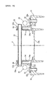
- the hinge member 50 is provided with left and right hinge plates 52, 52 fixed to the seat support 13b', a cylindrical hinge shaft 53 disposed across the left and right hinge plates 52, 52, and left and right hinge arms 54, 54 fixed by the hinge shaft 53, extending forward in the vehicle, and then fixed to the seat 9.
- Each of the hinge plates 52 has: a flange 52a fixed with a pair of front and rear bolts 55, 55 to the topside of the seat support 13b' at its left or right edge; and a plate body 52b extending upward from an inner edge of the flange 52a.
- the plate body 52b has a damper support 52f protruding forward from the plate body 52b.
- the hinge shaft 53 runs through the left and right plate bodies 52b, and is rotatably supported by bearing members 56, 56 fixed to the inner side of the respective plate bodies 52b.
- the hinge shaft 53 has a retaining pin 53a fitted thereonto at the outer side of the plate body 52b.
- the left and right hinge arms 54 are fixed to the hinge shaft 53 at the inner side of the respective bearing members 56.
- the left and right hinge arms 54 each have: a vertical side 54a extending obliquely downward from the hinge shaft 53 to the front; and a horizontal side 54b extending forward from a bottom end of the vertical side 54a generally in the horizontal direction, when the seat 9 is fully closed.
- An inverted triangle-shaped damper coupling section 54c is formed extending downward from the horizontal side 54b.
- the vertical side 54a and the horizontal side 54b have an J-shape overall, which prevents the hinge arm 54 from interfering with the tail cover 18b when the seat 9 is opened or closed.
- each hinge arm 54 is fixed to the downside of the seat bottom plate 9d with a pair of front and rear bolts 57 and nuts 57a.
- a portion of the seat bottom plate 9d, to which the hinge arm 54 is fixed, is formed in thickness greater than the other portions of the seat bottom plate 9d.
- the nuts 57a respectively use a cap nut not to expose the nuts when the seat is fully opened, which otherwise causes an unpleasant appearance.
- a switch 58 is installed to the left plate body 52b.
- the switch 58 is designed to turn on a lamp 58a, attached to a rear wall of the storage box 10, when the seat 9 is opened, or turn off the lamp 58a when the seat 9 is closed.
- the left and right hinge plates 52 each have a stopper 52c at their respective top edges.
- the stopper 52c is bent toward the center of the vehicle.
- the left and right hinge arms 54 each have a contact section 54d which comes in contact with the stopper 52c in order to regulate the position of the seat 9 at its fully-opened position.
- the seat 9 swings by a predetermined angle of about 70 degrees from its fully-closed position to its fully-opened position.
- the dampers 23 are extendable (stroke) dampers designed to generate axial urging force in the extending direction.
- the dampers 23 are provided on both the left and right sides in the vehicle width direction and are oriented in the vehicle front-rear direction to be tilted downward to the front. Details of the structure of the dampers 23 will be described below.
- the left and right dampers 23, 23 each have: a bottomed cylindrical cylinder 23a with hydraulic oil and high-pressure gas filled in; a piston 23b inserted into the cylinder 23a to be freely slidable within the cylinder 23a; a spring 23j interposed between the cylinder 23a and the piston 23b; a piston rod 23c whose one end is coupled with the piston 23b and other end protrudes outward from the cylinder 23a; and a seal member 23d fitted to the cylinder 23a at its opening and slidably contacting the piston rod 23c in an oil-tight manner (see FIG. 7 ).
- a coupling bracket 23e is connected to a bottom-side end of the cylinder 23a with the axis of the coupling bracket 23e offset toward the center of the vehicle with respect to the axis of the cylinder 23a.
- the left and right hinge plates 52 each have a coupling pin 52e and a damper support 52f.
- the coupling bracket 23e is rotatably coupled with the damper support 52f through the coupling pin 52e.
- a ball joint 23f is connected to a distal end of the piston rod 23c.
- the ball joint 23f has: a ball case 23g fitted onto the distal end of the piston rod 23c; a ball 23h supported by the ball case 23g; and a bolt 23i connected to the ball 23h.
- the bolt 23i is secured to the damper coupling section 54c of the hinge arm 54 with a cap nut 59.
- the left and right dampers 23 are disposed such that a seat-side coupling point B thereof is located rearward relative to a rear end surface 10d of the container section of the storage box 10, when the seat is closed.
- the left and right dampers 23 are also disposed adjacent to the inner sides of the left and right rear frame sections 13, respectively, and below the rear seat 9b.
- the left and right dampers 23 are oriented to be tilted downward to the front when the seat 9 is fully closed.
- the dampers 23 are tilted by an angle of about 40 degrees with respect to the horizontal line.
- a frame-side coupling point A of the dampers 23 of this embodiment is at a location rearward and higher than the seat-side coupling point B in the vehicle.
- the frame-side coupling point A is located between the seat-side coupling point B and a swing motion axis E of the hinge member 50, and closer to the swing motion axis E.
- the frame-side coupling point A is located in proximity of the hinge member 50 and lower than the swing motion axis E.
- the frame-side coupling point A of the left and right dampers 23 is located rearward relative to the rear end surface 9g of the seat 9.
- the seat-side coupling point B of the left and right dampers 23 is located forward relative to the rear end surface 9g of the seat 9 and rearward relative to the rear end surface 10d of the storage box 10.
- the frame-side coupling point A of the left and right dampers 23 is located on the opposite side of the seat 9 with respect to a straight line D connecting the seat-side coupling point B and the swing motion axis E of the hinge shaft 53. In other words, the frame-side coupling point A is located lower than the straight line D. This causes urging force of the dampers 23 to be applied to the seat 9 constantly in its opening direction. It should be noted that should the frame-side coupling point A be located on the side closer to the seat 9 with respect to the straight line D, or located higher than the straight line D, the urging force of the dampers 23 would be applied to the seat 9 in its closing direction.
- the seat 9 is supported at its rear end in the vertically swingable manner by the seat support 13b' through the hinge member 50, and the dampers 23 for applying urging force to the seat 9 in its opening direction are disposed such that the frame-side coupling point A of the dampers 23 is located rearward relative to the seat-side coupling point B in the vehicle.
- the dampers 23 rotate with the seat 9, while being kept oriented along the bottom surface of the seat 9 (see FIG. 6 ). Therefore, the dampers 23 do not obstruct the space between the seat 9 and the body frame 2. Consequently, the dampers 23 do not interfere with loading and unloading of the helmet or luggage into and from the storage box 10 or maintenance of the fuel tank 11 and its surroundings. This improves the workability in the loading and unloading as well as in the maintenance.
- the seat 9 is supported at its rear end by the rear end of the body frame 2 through the hinge member 50.
- the narrowed sections 9h are readily formed on the left and right sides of the front seat 9a, on which the rider is seated, without interference of the hinge member. This allows the rider's foot to be more firmly on the ground.
- the hinge member be located at the front end of the seat, a space for placing the hinge member needs to be secured of the seat, which accordingly lower the flexibility in configuration of the forward part of the seat.
- the frame-side coupling point A of the dampers 23 is located between the seat-side coupling point B and the swing motion axis E of the hinge shaft 53 and closer to the swing motion axis E. This avoids the interference of the dampers 23 and the hinge member 50, while increasing the angle at which the seat 9 is fully opened. Thereby, luggage is easily loaded in and unloaded from the storage box 10 located below the rear seat 9b.
- the rear seat 9b of the seat 9 is disposed at a location higher than the front seat 9a in order to avoid the interference of the rear wheel 8 caused by its up-down stroke and to ensure a sufficient capacity of the storage box.
- the front seat 9a is disposed at a location as low as possible in view of the rider's foot being more firmly on the ground.
- the seat 9 is tilted downward to the front.
- the angle at which the seat 9 is fully opened needs to be increased.
- the frame-side coupling point A of the dampers 23 is located forward relative to and closer to the swing motion axis E of the seat 9.
- the dampers 23 are disposed such that the frame-side coupling point A is located on the opposite side of the seat with respect to the straight line D connecting the seat-side coupling point B and the swing motion axis E of the hinge shaft 53, when the seat is fully closed. This enables urging force in the opening direction to be applied to the seat 9 at any position ranging from a fully-closed state to a fully-opened state, and therefore facilitates operation to open the seat.
- the urging force would be applied to the seat in its closing direction until the fully-closed seat is slightly opened or when the frame-side coupling point A crosses the straight line D from the side closer to the seat to the opposite side of the seat. Afterwards, the urging force would be applied to the seat in its opening direction. This creates a problem that the seat is undesirably heavy to open at the beginning.
- the dampers 23 are oriented downward to the front such that part of each damper 23 on the piston rod 23c side is located relatively lower, when the seat is fully closed.
- This causes the seal member 23d to be constantly dipped in hydraulic oil, and high-pressure gas to stay above the surface of the hydraulic oil.
- no high-pressure gas directly contacts the seal member 23d, which prevents leakage of high-pressure gas and maintains the damper function for a long period of time.
- the upper end aperture 10a of the storage box 10 is openable and closable by the seat 9, and the dampers 23 are disposed such that the seat-side coupling point B thereof is located rearward relative to the rear end surface 10d of the storage box 10.
- the placement of the dampers 23 does not cause the reduced capacity of the storage box 10, and a larger-sized box can be disposed.
- the dampers 23 are located at the rear of the storage box 10 and below the rear seat 9b and spaced therefrom. This ensures sufficient thickness of the seat cushion 9e of the rear seat 9b, and thus improves the passenger's riding comfort.
- the seat 9 is wholly oriented to be slightly tilted downward to the front. This increases the effective clearance between the seat 9 and the storage box 10, even though the seat 9 swings by the same angle. In this point of view, the ease of loading and unloading luggage also improves.
- the dampers 23 are disposed on both the left and right sides of the seat 9. This ensures, without using a large-sized damper, that urging force is applied to the large-sized seat 9 with its front seat 9a and rear seat 9b formed together into a single unit, while allowing the seat 9 to be kept upstanding at its fully-opened position.
- the urging force generating mechanism is a type of mechanism that generates urging force in the extending direction.
- the urging force generating mechanism may be another type of mechanism that generates urging force in the retracting direction.
- the urging force generating mechanism is a damper-type mechanism having urging force of the spring and the hydraulic damping function.
- the urging force generating mechanism may be a combination of a friction-type damping mechanism, a coil spring and the like, other than the damper-type mechanism.
- the urging force generating mechanism is designed to at least generate axial urging force, and may not necessarily have the damping function.
- the frame-side coupling point A is located to the seat-side coupling point B side from the swing motion axis E of the seat.
- the frame-side coupling point A is located at least rearward relative to the seat-side coupling point B in the vehicle front-rear direction in the embodiment, and may also be located rearward relative to the swing motion axis E of the seat.
- the seat-side coupling point B is disposed at a location rearward relative to the container section of the storage box 10, when the seat is closed.
- the seat-side coupling point B may be located overlapping the container section of the storage box, when viewed from the side of the vehicle.
- a straddle-type vehicle comprising: a body frame; a seat supported by the body frame in a vertically swingable manner; and an urging force generating mechanism for applying urging force to the seat in an opening direction, wherein the seat is supported at a rear end thereof in a vehicle front-rear direction by the body frame through a hinge member, thereby allowing the seat to swing vertically, and the urging force generating mechanism is axially extendable and generates axial urging force, in which one end of the urging force generating mechanism and the other end thereof are coupled with the body frame and the seat, respectively, and a frame-side coupling point is located rearward relative to a seat-side coupling point in the vehicle front-rear direction and located in proximity the hinge member.
- the urging force generating mechanism that generates urging force on the seat in its opening direction is designed to be axially extendable, and the frame-side coupling point thereof is located rearward relative to the seat-side coupling point in the vehicle.
- the urging force generating mechanism swings in its opening direction about the frame-side coupling point located rearward in the vehicle front-rear direction, while being kept oriented along the seat. Consequently, the urging force generating mechanism does not obstruct a space between the seat and the body frame.
- the urging force generating mechanism does not interfere with loading and unloading of luggage into and from a space below the seat used as a storage or maintenance of parts mounted below the seat and the like. This improves the workability in the loading and unloading as well as in the maintenance.
- the seat is supported at its rear end by the body frame through the hinge member.
- the front part of the seat, on which a rider is seated is narrowed in the vehicle width direction in order to allow the rider's foot to be more firmly on the ground.
- the hinge member which is located at the rear end of the seat, cannot possibly interfere with forming the narrow part of the seat, unlike a hinge member located at the front end of the seat.
- the frame-side coupling point of the urging force generating mechanism is provided at a location between the seat-side coupling point and a swing motion axis of the hinge member in terms of the positional relationship in the vehicle front-rear direction.
- the urging force generating mechanism is formed to generate urging force in an extending direction, and the frame-side coupling point is located on the opposite side of the seat with respect to a straight line connecting the seat-side coupling point and the swing motion axis of the hinge member.
- a storage box is disposed on the body frame, the seat is disposed such that an upper aperture of the storage box is openable and closable by the seat, and the urging force generating mechanism is provided such that at least the frame-side coupling point is located rearward relative to the storage box.
- the seat-side coupling point of the urging force generating mechanism is provided at a location rearward relative to a container section of the storage box, when the seat is closed.
- the urging force generating mechanism is oriented to be tilted downward to the front, when the seat is closed.
- a plurality of the urging force generating mechanisms which are arranged side by side in a vehicle width direction.
- a seat 9 is supported at a rear end of the seat 9 in the vehicle front-rear direction by a body frame 2 through a hinge shaft 53 in a vertically swinging manner.
- a damper (an urging force generating mechanism) 23 is a stroke damper that generates axial urging force.
- a frame-side coupling point A of the damper 23 is located rearward relative to a seat-side coupling point B of the damper 23 in the vehicle front-rear direction.
Landscapes
- Engineering & Computer Science (AREA)
- Mechanical Engineering (AREA)
- Automatic Cycles, And Cycles In General (AREA)
- Axle Suspensions And Sidecars For Cycles (AREA)
Abstract
Description
- The present invention relates to a straddle-type vehicle which can be driven by a rider in a straddle position so as to straddle a frame of said vehicle, in particular a motorcycle, having: a seat supported in a vertically swingable manner by a body frame through a hinge member; and an urging force generating mechanism for applying urging force to the seat in its opening direction.
- For example, in general, a scooter-type motorcycle has a structure in which a storage box is disposed below the seat mounted on the body frame, and an upper end aperture of the storage box is openable and closable by the seat.
- Occasionally, in this type of motorcycle, urging force is applied to the seat in its opening direction in order to facilitate operation to open/close the seat, and a damper (urging force generating mechanism) is disposed to hold the seat at its fully-opened position.
JP-Y-Sho 61-24469 - In such a conventional structure, the front end of the damper is coupled with the body frame, while the rear end of the damper is coupled with the seat. This causes the damper to be located obstructing a space between the seat and the body frame, when the seat is opened. Thus, there is a problem with the damper which interferes with loading and unloading of luggage or maintenance.
- The present invention is made in view of the foregoing circumstances, and an objective of the invention is to provide a straddle-type vehicle which facilitates loading and unloading of luggage and maintenance to be performed below the seat.
- According to the present invention, said objective is solved by a straddle-type vehicle, in particular motorcycle, comprising: a body frame; a seat supported by the body frame through a hinge member in a vertically swingable manner; and an urging force generating mechanism for applying urging force to the seat in an opening direction, the urging force generating mechanism being axially extendable so as to generate an axial urging force, one end of the urging force generating mechanism and the other end thereof being coupled with the body frame and the seat, respectively, wherein a frame-side coupling point of the urging force generating mechanism is located in proximity to the hinge member.
- Preferably, with regard to a front-rear direction of the straddle-type vehicle, the seat is supported at a rear end of the straddle-type vehicle by the body frame through the hinge member, thereby allowing the seat to swing vertically.
- Further, preferably the urging force generating mechanism is coupled to the seat at a seat-side coupling point, the frame-side coupling point being located rearwardly relative to said seat-side coupling point in front-rear direction of the straddle-type vehicle.
- Still further, preferably the frame-side coupling point, at which the urging force generating mechanism is coupled to the body frame, is provided at a location between the seat-side coupling point and a swing motion axis of the hinge member.
- Yet further still, preferably the frame-side coupling point is located on the opposite side of the seat with respect to a straight line connecting the seat-side coupling point and the swing motion axis of the hinge member.
- Preferably, the urging force generating mechanism is configured to generate urging force in an extending direction of said urging force generating mechanism.
- Further, preferably a storage box is disposed on the body frame, and the seat is configured to open and close a preferably upper aperture of said storage box.
- Still further, preferably the urging force generating mechanism is located such that at least the frame-side coupling point is located in front-rear direction of the straddle-type vehicle rearwardly of the storage box.
- Yet further still, preferably the seat-side coupling point of the urging force generating mechanism is located in front-rear direction of the straddle-type vehicle rearwardly of a container section of the storage box, preferably when the seat is closed.
- According to a preferred embodiment, the urging force generating mechanism is tilted downwardly to the front of the straddle-type vehicle, when the seat is closed, respectively, when the seat is in its substantially horizontal position.
- According to another preferred embodiment, a plurality of, preferably a pair of, urging force generating mechanisms are provided, which are arranged side by side in a width direction of the straddle-type vehicle.
- Preferably, the urging force generating mechanisms are provided on the left and right sides of the seat.
- Further, preferably the urging force generating mechanism is coupled to the seat by means of a ball joint.
- Still further, preferably the urging force generating mechanism comprises a spring and, preferably, a hydraulic or friction-type damping mechanism.
- In the following, the present invention is explained in greater detail with respect to several embodiments thereof in conjunction with the accompanying drawings, wherein:
- FIG. 1
- is a side view of a scooter-type motorcycle (straddle-type vehicle) according to an embodiment;
- FIG. 2
- is a top plan view of the motorcycle;
- FIG. 3
- is a side view of a seat area of the motorcycle;
- FIG. 4
- is a side view of a hinge member and a damper of the seat;
- FIG. 5
- is a sectional view of the hinge member (a sectional view taken along the line V-V in
FIG. 4 ); - FIG. 6
- is a side view showing the motion about the hinge member;
- FIG. 7
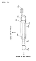
- is a top plan view of the damper;
- FIG. 8
- is a sectional view of a seat-side coupling point of the damper (a sectional view taken along the line VIII-VIII in
FIG. 4 ); and - FIG. 9
- is a sectional view of a part of the hinge member on the side fixed to the seat (a sectional view taken along the line IX-IX in
FIG. 4 ). - Among others, the following reference signs are used in the figures:
- 1: scooter-type motorcycle (straddle-type vehicle)
- 2: body frame
- 9: seat
- 10: storage box
- 13: left and right rear frame section (body frame)
- 13b: rear cross section (body frame)
- 23: damper (urging force generating mechanism)
- 50: hinge member
- 53: hinge shaft
- A:body frame-side coupling point
- B:seat-side coupling point
- D:straight line
- One embodiment will be described below with reference to the accompanying drawings.
-
FIGs. 1 to 9 illustrate a motorcycle (straddle-type vehicle) according to one embodiment. Therein, in general, a straddle-type vehicle is a vehicle having a body frame and a seat on which a rider can be seated straddling the body frame when being seated. Unless otherwise specified, the terms "right," "left," "front" and "rear" used in this embodiment refer to the right, left, front and rear sides when viewed from a rider seated on the seat. - In these figures, a
reference numeral 1 designates a scooter-type motorcycle. Themotorcycle 1 has: an underbonetype body frame 2; afront fork 6, which is supported steerably to the left and right by a head pipe (not shown) located at a front end of thebody frame 2, and which places afront wheel 4 andsteering handlebars 5 at a bottom end and a top end of thefront fork 6, respectively; an engine unit 7, which is mounted to thebody frame 2 at its middle part in the front-rear direction, and which places arear wheel 8 at a rear end of the engine unit 7; and astraddle seat 9 for two riders mounted to thebody frame 2 above the engine unit 7. - The
body frame 2 is provided with: a front frame (not shown) having left and right front frame sections extending from the head pipe obliquely downward to the rear; and a rear frame 13' having left and rightrear frame sections - The engine unit 7 has: an
engine body 7a fixed to thebody frame 2; and atransmission case 7b, supported in the vertically swingable manner by theengine body 7a, for transmitting engine power to therear wheel 8 pivotally supported at a rear end of thetransmission case 7b. - The
body frame 2 is enclosed with aresinous body cover 14. Thebody cover 14 has: afront cover 15 for covering the front, left and right sides of thefront fork 6; aleg shield 16, located rearward from thefront cover 15, for covering the front of the rider's legs; left and right side covers 18, 18 for covering the area around and beneath theseat 9 and the left and right sides of theengine body 7a; and left and right undercovers side cover 18. - Left and right
low footboards covers 17. - A
storage box 10 is disposed on thebody frame 2 below theseat 9. To be more specific, thestorage box 10 is located between the left and rightrear frame sections rear frame sections plural bolts 46. - The
storage box 10 has acontainer section 10a with a capacity sufficient to accommodate therein a helmet and the like. Thecontainer section 10a has anupper end aperture 10a' that is opened or closed by theseat 9. - A
fuel tank 11 is disposed in front of thecontainer section 10a of thestorage box 10. Thestorage box 10 has a load-receivingmember 10b for receiving load of the rider applied to theseat 9. To be more specific, thestorage box 10 is located between the left and rightrear frame sections rear frame sections plural bolts 46. - The load-receiving
member 10b is formed together with thestorage box 10 into a single unit. The load-receivingmember 10b has a shape extending along an outer surface shape of thefuel tank 11, and not contacting thefuel tank 11, and is fixed to thebody frame 2. - The
fuel tank 11 has a fuel cap 11a fitted to its upper wall. The fuel cap 11a is designed to open and close a fuel inlet. The fuel cap 11 a is exposed from above by tilting alid 11 b forward about its bottom edge, thelid 11 b being located on the forward side of theseat 9. - The
upper end aperture 10a of thestorage box 10 is at a location higher than top edges of the left and rightrear frame sections seat 9 such that theupper end aperture 10a is openable and closable. Thestorage box 10 has abottom wall 10c that is formed into a shape generally extending along bottom edges of the left and rightrear frame sections - As shown in
FIG. 3 , theseat 9 has afront seat 9a for a driver and arear seat 9b for a passenger, which are formed together into a single unit. Therear seat 9b is formed at a location higher than thefront seat 9a and is slightly tilted downward to the front, when viewed from the side. Theseat 9 has a structure in which a seat cushion 9e is disposed on a resinousseat bottom plate 9d, and an outer surface of the seat cushion 9e is covered with anouter cover 9f. - The
front seat 9a has narrowedsections sections front seat 9a is smaller than the dimension of the rearward part thereof in the vehicle width direction. This allows the rider's feet to be more firmly on the ground. - A
backrest 9c for supporting the rider's lower back is disposed on the border between thefront seat 9a and therear seat 9b. Below thebackrest 9c, astorage section 9i is formed by protruding theseat bottom plate 9d upward into a convex shape. In thestorage section 9i, atool kit 47 and ahelmet hanger 48 are accommodated and secured with arubber band 47a. - A
seat lock mechanism 21 for locking theseat 9 to its fully-closed position is disposed between thestorage box 10 and the load-receivingmember 10b below thefront seat 9a. - The
seat 9 is supported at its rear end by the left and rightrear frame sections hinge member 50. This allows theseat 9 to swing vertically. In addition, an axially extendable damper (a urging force generating mechanism) 23 for applying urging force to theseat 9 in its opening direction is each disposed between the left and rightrear frame sections seat 9. Details of the structure of thedampers 23 will be described below. - The rear frame 13' is a single-piece casting made up of: the left and right
rear frame sections rear frame sections rear cross section 13b for connecting the rear end top edges of the left and rightrear frame sections rear frame sections triangular sidewall surfaces storage box 10 is disposed between the left and right sidewall surfaces 13a, 13a. - The
rear cross section 13b has aseat support 13b' protruding from and formed integral with therear cross section 13b, such that theseat support 13b' is located at the rear of arear end surface 9g of theseat 9. Thehinge member 50 is disposed above theseat support 13b'. Areference numeral 51 designates a tail light mounting bracket that is fixed to therear cross section 13b with a bolt to protrude rearward from therear cross section 13b. - The left and right side covers 18 have respective
rear ends tail cover 18b located on the top ends of the left and rightrear ends 18a. Therear cross section 13b, thehinge member 50 and thebracket 51 are covered with therear ends 18a and thetail cover 18b (seeFIGs. 1 and2 ). - The
hinge member 50 is provided with left andright hinge plates seat support 13b', acylindrical hinge shaft 53 disposed across the left andright hinge plates arms hinge shaft 53, extending forward in the vehicle, and then fixed to theseat 9. - Each of the
hinge plates 52 has: aflange 52a fixed with a pair of front andrear bolts seat support 13b' at its left or right edge; and aplate body 52b extending upward from an inner edge of theflange 52a. Theplate body 52b has adamper support 52f protruding forward from theplate body 52b. - The
hinge shaft 53 runs through the left andright plate bodies 52b, and is rotatably supported by bearingmembers respective plate bodies 52b. Thehinge shaft 53 has a retainingpin 53a fitted thereonto at the outer side of theplate body 52b. - The left and right hinge
arms 54 are fixed to thehinge shaft 53 at the inner side of therespective bearing members 56. The left and right hingearms 54 each have: avertical side 54a extending obliquely downward from thehinge shaft 53 to the front; and ahorizontal side 54b extending forward from a bottom end of thevertical side 54a generally in the horizontal direction, when theseat 9 is fully closed. An inverted triangle-shapeddamper coupling section 54c is formed extending downward from thehorizontal side 54b. Thevertical side 54a and thehorizontal side 54b have an J-shape overall, which prevents thehinge arm 54 from interfering with thetail cover 18b when theseat 9 is opened or closed. - The
horizontal side 54b of eachhinge arm 54 is fixed to the downside of theseat bottom plate 9d with a pair of front andrear bolts 57 and nuts 57a. A portion of theseat bottom plate 9d, to which thehinge arm 54 is fixed, is formed in thickness greater than the other portions of theseat bottom plate 9d. The nuts 57a respectively use a cap nut not to expose the nuts when the seat is fully opened, which otherwise causes an unpleasant appearance. - A
switch 58 is installed to theleft plate body 52b. Theswitch 58 is designed to turn on alamp 58a, attached to a rear wall of thestorage box 10, when theseat 9 is opened, or turn off thelamp 58a when theseat 9 is closed. - The left and
right hinge plates 52 each have astopper 52c at their respective top edges. Thestopper 52c is bent toward the center of the vehicle. The left and right hingearms 54 each have acontact section 54d which comes in contact with thestopper 52c in order to regulate the position of theseat 9 at its fully-opened position. Theseat 9 swings by a predetermined angle of about 70 degrees from its fully-closed position to its fully-opened position. - The
dampers 23 are extendable (stroke) dampers designed to generate axial urging force in the extending direction. Thedampers 23 are provided on both the left and right sides in the vehicle width direction and are oriented in the vehicle front-rear direction to be tilted downward to the front. Details of the structure of thedampers 23 will be described below. - The left and
right dampers cylindrical cylinder 23a with hydraulic oil and high-pressure gas filled in; apiston 23b inserted into thecylinder 23a to be freely slidable within thecylinder 23a; aspring 23j interposed between thecylinder 23a and thepiston 23b; apiston rod 23c whose one end is coupled with thepiston 23b and other end protrudes outward from thecylinder 23a; and aseal member 23d fitted to thecylinder 23a at its opening and slidably contacting thepiston rod 23c in an oil-tight manner (seeFIG. 7 ). - A
coupling bracket 23e is connected to a bottom-side end of thecylinder 23a with the axis of thecoupling bracket 23e offset toward the center of the vehicle with respect to the axis of thecylinder 23a. The left andright hinge plates 52 each have acoupling pin 52e and adamper support 52f. Thecoupling bracket 23e is rotatably coupled with thedamper support 52f through thecoupling pin 52e. A ball joint 23f is connected to a distal end of thepiston rod 23c. The ball joint 23f has: aball case 23g fitted onto the distal end of thepiston rod 23c; aball 23h supported by theball case 23g; and a bolt 23i connected to theball 23h. The bolt 23i is secured to thedamper coupling section 54c of thehinge arm 54 with acap nut 59. - The left and
right dampers 23 are disposed such that a seat-side coupling point B thereof is located rearward relative to arear end surface 10d of the container section of thestorage box 10, when the seat is closed. The left andright dampers 23 are also disposed adjacent to the inner sides of the left and rightrear frame sections 13, respectively, and below therear seat 9b. - The left and
right dampers 23 are oriented to be tilted downward to the front when theseat 9 is fully closed. In the embodiment, thedampers 23 are tilted by an angle of about 40 degrees with respect to the horizontal line. - As shown in
FIG. 4 , a frame-side coupling point A of thedampers 23 of this embodiment is at a location rearward and higher than the seat-side coupling point B in the vehicle. In terms of the positional relationship in the vehicle front-rear direction, the frame-side coupling point A is located between the seat-side coupling point B and a swing motion axis E of thehinge member 50, and closer to the swing motion axis E. In other words, the frame-side coupling point A is located in proximity of thehinge member 50 and lower than the swing motion axis E. - The frame-side coupling point A of the left and
right dampers 23 is located rearward relative to therear end surface 9g of theseat 9. The seat-side coupling point B of the left andright dampers 23 is located forward relative to therear end surface 9g of theseat 9 and rearward relative to therear end surface 10d of thestorage box 10. - Further, the frame-side coupling point A of the left and
right dampers 23 is located on the opposite side of theseat 9 with respect to a straight line D connecting the seat-side coupling point B and the swing motion axis E of thehinge shaft 53. In other words, the frame-side coupling point A is located lower than the straight line D. This causes urging force of thedampers 23 to be applied to theseat 9 constantly in its opening direction. It should be noted that should the frame-side coupling point A be located on the side closer to theseat 9 with respect to the straight line D, or located higher than the straight line D, the urging force of thedampers 23 would be applied to theseat 9 in its closing direction. - According to the embodiment, the
seat 9 is supported at its rear end in the vertically swingable manner by theseat support 13b' through thehinge member 50, and thedampers 23 for applying urging force to theseat 9 in its opening direction are disposed such that the frame-side coupling point A of thedampers 23 is located rearward relative to the seat-side coupling point B in the vehicle. Thus, when theseat 9 is opened, thedampers 23 rotate with theseat 9, while being kept oriented along the bottom surface of the seat 9 (seeFIG. 6 ). Therefore, thedampers 23 do not obstruct the space between theseat 9 and thebody frame 2. Consequently, thedampers 23 do not interfere with loading and unloading of the helmet or luggage into and from thestorage box 10 or maintenance of thefuel tank 11 and its surroundings. This improves the workability in the loading and unloading as well as in the maintenance. - According to the embodiment, the
seat 9 is supported at its rear end by the rear end of thebody frame 2 through thehinge member 50. This offers greater flexibility in design and configuration of the forward part of theseat 9. For example, the narrowedsections 9h are readily formed on the left and right sides of thefront seat 9a, on which the rider is seated, without interference of the hinge member. This allows the rider's foot to be more firmly on the ground. It should be noted that should the hinge member be located at the front end of the seat, a space for placing the hinge member needs to be secured of the seat, which accordingly lower the flexibility in configuration of the forward part of the seat. - According to the embodiment, the frame-side coupling point A of the
dampers 23 is located between the seat-side coupling point B and the swing motion axis E of thehinge shaft 53 and closer to the swing motion axis E. This avoids the interference of thedampers 23 and thehinge member 50, while increasing the angle at which theseat 9 is fully opened. Thereby, luggage is easily loaded in and unloaded from thestorage box 10 located below therear seat 9b. - The
rear seat 9b of theseat 9 is disposed at a location higher than thefront seat 9a in order to avoid the interference of therear wheel 8 caused by its up-down stroke and to ensure a sufficient capacity of the storage box. In contrast, thefront seat 9a is disposed at a location as low as possible in view of the rider's foot being more firmly on the ground. Thus, theseat 9 is tilted downward to the front. In order to open thisseat 9 to a position that allows for loading and unloading of luggage, the angle at which theseat 9 is fully opened needs to be increased. According to the embodiment, the frame-side coupling point A of thedampers 23 is located forward relative to and closer to the swing motion axis E of theseat 9. This results in a shorter damper stroke to be required, while ensuring a greater angle at which the seat is fully opened. It should be noted that as the frame-side coupling point A is located apart from the swing motion axis E of the seat, a longer damper stroke is required. - According to the embodiment, the
dampers 23 are disposed such that the frame-side coupling point A is located on the opposite side of the seat with respect to the straight line D connecting the seat-side coupling point B and the swing motion axis E of thehinge shaft 53, when the seat is fully closed. This enables urging force in the opening direction to be applied to theseat 9 at any position ranging from a fully-closed state to a fully-opened state, and therefore facilitates operation to open the seat. Assuming that the frame-side coupling point A is located on the side closer to the seat with respect to the straight line D, the urging force would be applied to the seat in its closing direction until the fully-closed seat is slightly opened or when the frame-side coupling point A crosses the straight line D from the side closer to the seat to the opposite side of the seat. Afterwards, the urging force would be applied to the seat in its opening direction. This creates a problem that the seat is undesirably heavy to open at the beginning. - According to the embodiment, the
dampers 23 are oriented downward to the front such that part of eachdamper 23 on thepiston rod 23c side is located relatively lower, when the seat is fully closed. This causes theseal member 23d to be constantly dipped in hydraulic oil, and high-pressure gas to stay above the surface of the hydraulic oil. Thus, no high-pressure gas directly contacts theseal member 23d, which prevents leakage of high-pressure gas and maintains the damper function for a long period of time. - According to the embodiment, the
upper end aperture 10a of thestorage box 10 is openable and closable by theseat 9, and thedampers 23 are disposed such that the seat-side coupling point B thereof is located rearward relative to therear end surface 10d of thestorage box 10. Thus, the placement of thedampers 23 does not cause the reduced capacity of thestorage box 10, and a larger-sized box can be disposed. - The
dampers 23 are located at the rear of thestorage box 10 and below therear seat 9b and spaced therefrom. This ensures sufficient thickness of the seat cushion 9e of therear seat 9b, and thus improves the passenger's riding comfort. - According to the embodiment, the
seat 9 is wholly oriented to be slightly tilted downward to the front. This increases the effective clearance between theseat 9 and thestorage box 10, even though theseat 9 swings by the same angle. In this point of view, the ease of loading and unloading luggage also improves. - According to the embodiment, the
dampers 23 are disposed on both the left and right sides of theseat 9. This ensures, without using a large-sized damper, that urging force is applied to the large-sized seat 9 with itsfront seat 9a andrear seat 9b formed together into a single unit, while allowing theseat 9 to be kept upstanding at its fully-opened position. - In the above description of the embodiment, there are provided two of the
dampers 23. However, it should be understood that there may be provided one of or more than two of the dampers in the embodiment. - In addition, in the above description of the embodiment, the urging force generating mechanism is a type of mechanism that generates urging force in the extending direction. However, it should be understood that the urging force generating mechanism may be another type of mechanism that generates urging force in the retracting direction.
- Further, in the above description of the embodiment, the urging force generating mechanism is a damper-type mechanism having urging force of the spring and the hydraulic damping function. However, it should be understood that the urging force generating mechanism may be a combination of a friction-type damping mechanism, a coil spring and the like, other than the damper-type mechanism. It should be further understood that the urging force generating mechanism is designed to at least generate axial urging force, and may not necessarily have the damping function.
- Still further, in the above description of the embodiment, the frame-side coupling point A is located to the seat-side coupling point B side from the swing motion axis E of the seat. However, it should be understood that the frame-side coupling point A is located at least rearward relative to the seat-side coupling point B in the vehicle front-rear direction in the embodiment, and may also be located rearward relative to the swing motion axis E of the seat.
- Still further, in the above description of the embodiment, the seat-side coupling point B is disposed at a location rearward relative to the container section of the
storage box 10, when the seat is closed. However, it should be understood that the seat-side coupling point B may be located overlapping the container section of the storage box, when viewed from the side of the vehicle. - Accordingly, the description above discloses (among others) an embodiment of a straddle-type vehicle comprising: a body frame; a seat supported by the body frame in a vertically swingable manner; and an urging force generating mechanism for applying urging force to the seat in an opening direction, wherein the seat is supported at a rear end thereof in a vehicle front-rear direction by the body frame through a hinge member, thereby allowing the seat to swing vertically, and the urging force generating mechanism is axially extendable and generates axial urging force, in which one end of the urging force generating mechanism and the other end thereof are coupled with the body frame and the seat, respectively, and a frame-side coupling point is located rearward relative to a seat-side coupling point in the vehicle front-rear direction and located in proximity the hinge member.
- Accordingly, In the straddle-type vehicle, the urging force generating mechanism that generates urging force on the seat in its opening direction is designed to be axially extendable, and the frame-side coupling point thereof is located rearward relative to the seat-side coupling point in the vehicle. Thus, as the seat swings in its opening direction, the urging force generating mechanism swings in its opening direction about the frame-side coupling point located rearward in the vehicle front-rear direction, while being kept oriented along the seat. Consequently, the urging force generating mechanism does not obstruct a space between the seat and the body frame. Therefore, the urging force generating mechanism does not interfere with loading and unloading of luggage into and from a space below the seat used as a storage or maintenance of parts mounted below the seat and the like. This improves the workability in the loading and unloading as well as in the maintenance.
- Moreover, the seat is supported at its rear end by the body frame through the hinge member. This offers greater flexibility in configuration of a front part of the seat. For example, the front part of the seat, on which a rider is seated, is narrowed in the vehicle width direction in order to allow the rider's foot to be more firmly on the ground. In such a case, the hinge member, which is located at the rear end of the seat, cannot possibly interfere with forming the narrow part of the seat, unlike a hinge member located at the front end of the seat.
- Preferably, the frame-side coupling point of the urging force generating mechanism is provided at a location between the seat-side coupling point and a swing motion axis of the hinge member in terms of the positional relationship in the vehicle front-rear direction.
- Preferably, the urging force generating mechanism is formed to generate urging force in an extending direction, and the frame-side coupling point is located on the opposite side of the seat with respect to a straight line connecting the seat-side coupling point and the swing motion axis of the hinge member.
- Further, preferably a storage box is disposed on the body frame, the seat is disposed such that an upper aperture of the storage box is openable and closable by the seat, and the urging force generating mechanism is provided such that at least the frame-side coupling point is located rearward relative to the storage box.
- Preferably, the seat-side coupling point of the urging force generating mechanism is provided at a location rearward relative to a container section of the storage box, when the seat is closed.
- According to another preferred aspect, the urging force generating mechanism is oriented to be tilted downward to the front, when the seat is closed.
- According to a further preferred aspect, there are provided a plurality of the urging force generating mechanisms, which are arranged side by side in a vehicle width direction.
- In order to provide a straddle-type vehicle which facilitates loading and unloading of luggage as well as maintenance, it is suggested that a
seat 9 is supported at a rear end of theseat 9 in the vehicle front-rear direction by abody frame 2 through ahinge shaft 53 in a vertically swinging manner. A damper (an urging force generating mechanism) 23 is a stroke damper that generates axial urging force. A frame-side coupling point A of thedamper 23 is located rearward relative to a seat-side coupling point B of thedamper 23 in the vehicle front-rear direction.
Claims (14)
- Straddle-type vehicle, in particular motorcycle, comprising:a body frame (2);a seat (9) supported by the body frame (2) through a hinge member (50) in a vertically swingable manner; andan urging force generating mechanism (23) for applying urging force to the seat (9) in an opening direction, the urging force generating mechanism (23) being axially extendable so as to generate an axial urging force, one end of the urging force generating mechanism (23) and the other end thereof being coupled with the body frame (2) and the seat (9), respectively,wherein a frame-side coupling point (A) of the urging force generating mechanism (23) is located in proximity to the hinge member (50).
- Straddle-type vehicle according to claim 1, wherein, with regard to a front-rear direction of the straddle-type vehicle, the seat (9) is supported at a rear end of the straddle-type vehicle by the body frame (2) through the hinge member (50), thereby allowing the seat (9) to swing vertically.
- Straddle-type vehicle according to claim 1 or 2, wherein the urging force generating mechanism (23) is coupled to the seat (9) at a seat-side coupling point (B), the frame-side coupling point (A) being located rearwardly relative to said seat-side coupling point (B) in front-rear direction of the straddle-type vehicle.
- Straddle-type vehicle according to claim 3, wherein the frame-side coupling point (A), at which the urging force generating mechanism (23) is coupled to the body frame (2), is provided at a location between the seat-side coupling point (B) and a swing motion axis (E) of the hinge member (50).
- Straddle-type vehicle according to claim 4, wherein the frame-side coupling point (A) is located on the opposite side of the seat (9) with respect to a straight line (D) connecting the seat-side coupling point (B) and the swing motion axis (E) of the hinge member (50).
- Straddle-type vehicle according to one of claims 1 to 5, wherein the urging force generating mechanism (23) is configured to generate urging force in an extending direction of said urging force generating mechanism (23).
- Straddle-type vehicle according to one of claims 1 to 6, wherein a storage box (10) is disposed on the body frame (2), and the seat (9) is configured to open and close a preferably upper aperture of said storage box (10).
- Straddle-type vehicle according to claim 7, wherein the urging force generating mechanism (23) is located such that at least the frame-side coupling point (A) is located in front-rear direction of the straddle-type vehicle rearwardly of the storage box (10).
- Straddle-type vehicle according to claim 7 or 8, wherein the seat-side coupling point (B) of the urging force generating mechanism (23) is located in front-rear direction of the straddle-type vehicle rearwardly of a container section (10a) of the storage box (10), preferably when the seat (9) is closed.
- Straddle-type vehicle according to one of claims 1 to 9, wherein the urging force generating mechanism (23) is tilted downwardly to the front of the straddle-type vehicle, when the seat (9) is closed, respectively, when the seat (9) is in its substantially horizontal position.
- Straddle-type vehicle according to one of claims 1 to 10, wherein a plurality of, preferably a pair of, urging force generating mechanisms (23) are provided, which are arranged side by side in a width direction of the straddle-type vehicle.
- Straddle-type vehicle according to claim 11, wherein the urging force generating mechanisms (23) are provided on the left and right sides of the seat (9).
- Straddle-type vehicle according to one of claims 1 to 12, wherein the urging force generating mechanism (23) is coupled to the seat (9) by means of a ball joint (23f).
- Straddle-type vehicle according to one of claims 1 to 13, wherein the urging force generating mechanism (23) comprises a spring and, preferably, a hydraulic or friction-type damping mechanism.
Applications Claiming Priority (1)
| Application Number | Priority Date | Filing Date | Title |
|---|---|---|---|
| JP2007239292A JP2009067285A (en) | 2007-09-14 | 2007-09-14 | Saddle riding vehicle |
Publications (2)
| Publication Number | Publication Date |
|---|---|
| EP2036804A1 true EP2036804A1 (en) | 2009-03-18 |
| EP2036804B1 EP2036804B1 (en) | 2014-05-21 |
Family
ID=39791218
Family Applications (1)
| Application Number | Title | Priority Date | Filing Date |
|---|---|---|---|
| EP20080009951 Active EP2036804B1 (en) | 2007-09-14 | 2008-05-30 | Straddle-type vehicle |
Country Status (5)
| Country | Link |
|---|---|
| EP (1) | EP2036804B1 (en) |
| JP (1) | JP2009067285A (en) |
| CN (1) | CN101386314B (en) |
| ES (1) | ES2467915T3 (en) |
| TW (1) | TWI347282B (en) |
Cited By (2)
| Publication number | Priority date | Publication date | Assignee | Title |
|---|---|---|---|---|
| EP2891593A4 (en) * | 2012-08-31 | 2016-03-30 | Honda Motor Co Ltd | Vehicle seat peripheral structure |
| EP4640539A1 (en) * | 2024-04-23 | 2025-10-29 | Suzuki Motor Corporation | Seat structure of saddle-type vehicle with opening assist damper |
Families Citing this family (1)
| Publication number | Priority date | Publication date | Assignee | Title |
|---|---|---|---|---|
| JP2019137330A (en) * | 2018-02-14 | 2019-08-22 | ヤマハ発動機株式会社 | Saddle-riding type vehicle |
Citations (5)
| Publication number | Priority date | Publication date | Assignee | Title |
|---|---|---|---|---|
| JPS6124469Y2 (en) | 1980-09-17 | 1986-07-22 | ||
| US5107949A (en) * | 1988-09-14 | 1992-04-28 | Honda Giken Kogyo Kabushiki Kaisha | Motorcycle |
| EP1063153A2 (en) * | 1999-06-25 | 2000-12-27 | Yamaha Hatsudoki Kabushiki Kaisha | An arrangement of a damper for controlling opening and closing movement of a vehicle seat |
| EP1245481A1 (en) | 2001-03-26 | 2002-10-02 | Honda Giken Kogyo Kabushiki Kaisha | Seat attachment structure for scooter type vehicles |
| EP1557349A1 (en) * | 2004-01-20 | 2005-07-27 | HONDA MOTOR CO., Ltd. | Unlocking member arranging structure for vehicles |
-
2007
- 2007-09-14 JP JP2007239292A patent/JP2009067285A/en not_active Withdrawn
-
2008
- 2008-04-14 TW TW097113547A patent/TWI347282B/en active
- 2008-05-22 CN CN 200810097670 patent/CN101386314B/en active Active
- 2008-05-30 EP EP20080009951 patent/EP2036804B1/en active Active
- 2008-05-30 ES ES08009951T patent/ES2467915T3/en active Active
Patent Citations (5)
| Publication number | Priority date | Publication date | Assignee | Title |
|---|---|---|---|---|
| JPS6124469Y2 (en) | 1980-09-17 | 1986-07-22 | ||
| US5107949A (en) * | 1988-09-14 | 1992-04-28 | Honda Giken Kogyo Kabushiki Kaisha | Motorcycle |
| EP1063153A2 (en) * | 1999-06-25 | 2000-12-27 | Yamaha Hatsudoki Kabushiki Kaisha | An arrangement of a damper for controlling opening and closing movement of a vehicle seat |
| EP1245481A1 (en) | 2001-03-26 | 2002-10-02 | Honda Giken Kogyo Kabushiki Kaisha | Seat attachment structure for scooter type vehicles |
| EP1557349A1 (en) * | 2004-01-20 | 2005-07-27 | HONDA MOTOR CO., Ltd. | Unlocking member arranging structure for vehicles |
Cited By (2)
| Publication number | Priority date | Publication date | Assignee | Title |
|---|---|---|---|---|
| EP2891593A4 (en) * | 2012-08-31 | 2016-03-30 | Honda Motor Co Ltd | Vehicle seat peripheral structure |
| EP4640539A1 (en) * | 2024-04-23 | 2025-10-29 | Suzuki Motor Corporation | Seat structure of saddle-type vehicle with opening assist damper |
Also Published As
| Publication number | Publication date |
|---|---|
| TWI347282B (en) | 2011-08-21 |
| ES2467915T3 (en) | 2014-06-13 |
| EP2036804B1 (en) | 2014-05-21 |
| TW200911603A (en) | 2009-03-16 |
| CN101386314A (en) | 2009-03-18 |
| CN101386314B (en) | 2013-07-24 |
| JP2009067285A (en) | 2009-04-02 |
Similar Documents
| Publication | Publication Date | Title |
|---|---|---|
| EP2982586B1 (en) | Vehicle | |
| EP2982585B1 (en) | Vehicle | |
| EP2036804B1 (en) | Straddle-type vehicle | |
| US7828103B2 (en) | Vehicle | |
| JP2008201286A (en) | Motorcycle | |
| US10421520B2 (en) | Saddle riding type vehicle | |
| JP2000118469A (en) | Body frame structure of scooter type motorcycle | |
| JP5088088B2 (en) | Scooter-type vehicle intake system | |
| JP4739038B2 (en) | Rear cushion arrangement structure for motorcycles | |
| JP4900293B2 (en) | Exhaust gas sensor device for motorcycles | |
| JP5088087B2 (en) | Rear body structure of scooter type vehicle | |
| JPH08253188A (en) | Bicycle rear wheel suspension | |
| CN103448845A (en) | Mini-sized motorcycle-type vehicle | |
| JP6937336B2 (en) | Saddle-type vehicle | |
| AU2012200595B2 (en) | Saddle-ride type vehicle | |
| JP3676487B2 (en) | Scooter type vehicle | |
| JP3676798B2 (en) | Scooter-type vehicle body structure | |
| JP5889948B2 (en) | Vehicle footrest structure | |
| JP5958095B2 (en) | Helmet storage structure for saddle riding type vehicles | |
| EP4324730B1 (en) | Rear structure of straddle-type vehicle | |
| JP2014076759A (en) | Motor cycle | |
| JP2009101889A (en) | Scooter type motorcycle | |
| JP6008894B2 (en) | Saddle riding type vehicle | |
| JP2015193350A (en) | Saddle riding | |
| JP6979436B2 (en) | Saddle-type vehicle |
Legal Events
| Date | Code | Title | Description |
|---|---|---|---|
| PUAI | Public reference made under article 153(3) epc to a published international application that has entered the european phase |
Free format text: ORIGINAL CODE: 0009012 |
|
| 17P | Request for examination filed |
Effective date: 20090121 |
|
| AK | Designated contracting states |
Kind code of ref document: A1 Designated state(s): AT BE BG CH CY CZ DE DK EE ES FI FR GB GR HR HU IE IS IT LI LT LU LV MC MT NL NO PL PT RO SE SI SK TR |
|
| AX | Request for extension of the european patent |
Extension state: AL BA MK RS |
|
| AKX | Designation fees paid |
Designated state(s): AT BE BG CH CY CZ DE DK EE ES FI FR GB GR HR HU IE IS IT LI LT LU LV MC MT NL NO PL PT RO SE SI SK TR |
|
| 17Q | First examination report despatched |
Effective date: 20091203 |
|
| GRAJ | Information related to disapproval of communication of intention to grant by the applicant or resumption of examination proceedings by the epo deleted |
Free format text: ORIGINAL CODE: EPIDOSDIGR1 |
|
| GRAP | Despatch of communication of intention to grant a patent |
Free format text: ORIGINAL CODE: EPIDOSNIGR1 |
|
| RAP1 | Party data changed (applicant data changed or rights of an application transferred) |
Owner name: YAMAHA HATSUDOKI KABUSHIKI KAISHA |
|
| INTG | Intention to grant announced |
Effective date: 20131209 |
|
| RIN1 | Information on inventor provided before grant (corrected) |
Inventor name: HIRAKAWA, NOBUHIKO Inventor name: TOMINAGA, SHUJI |
|
| GRAS | Grant fee paid |
Free format text: ORIGINAL CODE: EPIDOSNIGR3 |
|
| GRAA | (expected) grant |
Free format text: ORIGINAL CODE: 0009210 |
|
| AK | Designated contracting states |
Kind code of ref document: B1 Designated state(s): AT BE BG CH CY CZ DE DK EE ES FI FR GB GR HR HU IE IS IT LI LT LU LV MC MT NL NO PL PT RO SE SI SK TR |
|
| REG | Reference to a national code |
Ref country code: GB Ref legal event code: FG4D |
|
| REG | Reference to a national code |
Ref country code: CH Ref legal event code: EP |
|
| REG | Reference to a national code |
Ref country code: ES Ref legal event code: FG2A Ref document number: 2467915 Country of ref document: ES Kind code of ref document: T3 Effective date: 20140613 |
|
| REG | Reference to a national code |
Ref country code: AT Ref legal event code: REF Ref document number: 669443 Country of ref document: AT Kind code of ref document: T Effective date: 20140615 |
|
| REG | Reference to a national code |
Ref country code: IE Ref legal event code: FG4D |
|
| REG | Reference to a national code |
Ref country code: DE Ref legal event code: R096 Ref document number: 602008032370 Country of ref document: DE Effective date: 20140703 |
|
| REG | Reference to a national code |
Ref country code: AT Ref legal event code: MK05 Ref document number: 669443 Country of ref document: AT Kind code of ref document: T Effective date: 20140521 Ref country code: NL Ref legal event code: VDEP Effective date: 20140521 |
|
| REG | Reference to a national code |
Ref country code: LT Ref legal event code: MG4D |
|
| PG25 | Lapsed in a contracting state [announced via postgrant information from national office to epo] |
Ref country code: GR Free format text: LAPSE BECAUSE OF FAILURE TO SUBMIT A TRANSLATION OF THE DESCRIPTION OR TO PAY THE FEE WITHIN THE PRESCRIBED TIME-LIMIT Effective date: 20140822 Ref country code: LT Free format text: LAPSE BECAUSE OF FAILURE TO SUBMIT A TRANSLATION OF THE DESCRIPTION OR TO PAY THE FEE WITHIN THE PRESCRIBED TIME-LIMIT Effective date: 20140521 Ref country code: IS Free format text: LAPSE BECAUSE OF FAILURE TO SUBMIT A TRANSLATION OF THE DESCRIPTION OR TO PAY THE FEE WITHIN THE PRESCRIBED TIME-LIMIT Effective date: 20140921 Ref country code: NO Free format text: LAPSE BECAUSE OF FAILURE TO SUBMIT A TRANSLATION OF THE DESCRIPTION OR TO PAY THE FEE WITHIN THE PRESCRIBED TIME-LIMIT Effective date: 20140821 Ref country code: FI Free format text: LAPSE BECAUSE OF FAILURE TO SUBMIT A TRANSLATION OF THE DESCRIPTION OR TO PAY THE FEE WITHIN THE PRESCRIBED TIME-LIMIT Effective date: 20140521 |
|
| PG25 | Lapsed in a contracting state [announced via postgrant information from national office to epo] |
Ref country code: SE Free format text: LAPSE BECAUSE OF FAILURE TO SUBMIT A TRANSLATION OF THE DESCRIPTION OR TO PAY THE FEE WITHIN THE PRESCRIBED TIME-LIMIT Effective date: 20140521 Ref country code: PL Free format text: LAPSE BECAUSE OF FAILURE TO SUBMIT A TRANSLATION OF THE DESCRIPTION OR TO PAY THE FEE WITHIN THE PRESCRIBED TIME-LIMIT Effective date: 20140521 Ref country code: AT Free format text: LAPSE BECAUSE OF FAILURE TO SUBMIT A TRANSLATION OF THE DESCRIPTION OR TO PAY THE FEE WITHIN THE PRESCRIBED TIME-LIMIT Effective date: 20140521 Ref country code: LV Free format text: LAPSE BECAUSE OF FAILURE TO SUBMIT A TRANSLATION OF THE DESCRIPTION OR TO PAY THE FEE WITHIN THE PRESCRIBED TIME-LIMIT Effective date: 20140521 Ref country code: HR Free format text: LAPSE BECAUSE OF FAILURE TO SUBMIT A TRANSLATION OF THE DESCRIPTION OR TO PAY THE FEE WITHIN THE PRESCRIBED TIME-LIMIT Effective date: 20140521 |
|
| PG25 | Lapsed in a contracting state [announced via postgrant information from national office to epo] |
Ref country code: PT Free format text: LAPSE BECAUSE OF FAILURE TO SUBMIT A TRANSLATION OF THE DESCRIPTION OR TO PAY THE FEE WITHIN THE PRESCRIBED TIME-LIMIT Effective date: 20140922 |
|
| REG | Reference to a national code |
Ref country code: CH Ref legal event code: PL |
|
| PG25 | Lapsed in a contracting state [announced via postgrant information from national office to epo] |
Ref country code: CZ Free format text: LAPSE BECAUSE OF FAILURE TO SUBMIT A TRANSLATION OF THE DESCRIPTION OR TO PAY THE FEE WITHIN THE PRESCRIBED TIME-LIMIT Effective date: 20140521 Ref country code: BE Free format text: LAPSE BECAUSE OF FAILURE TO SUBMIT A TRANSLATION OF THE DESCRIPTION OR TO PAY THE FEE WITHIN THE PRESCRIBED TIME-LIMIT Effective date: 20140521 Ref country code: SK Free format text: LAPSE BECAUSE OF FAILURE TO SUBMIT A TRANSLATION OF THE DESCRIPTION OR TO PAY THE FEE WITHIN THE PRESCRIBED TIME-LIMIT Effective date: 20140521 Ref country code: LI Free format text: LAPSE BECAUSE OF NON-PAYMENT OF DUE FEES Effective date: 20140531 Ref country code: EE Free format text: LAPSE BECAUSE OF FAILURE TO SUBMIT A TRANSLATION OF THE DESCRIPTION OR TO PAY THE FEE WITHIN THE PRESCRIBED TIME-LIMIT Effective date: 20140521 Ref country code: DK Free format text: LAPSE BECAUSE OF FAILURE TO SUBMIT A TRANSLATION OF THE DESCRIPTION OR TO PAY THE FEE WITHIN THE PRESCRIBED TIME-LIMIT Effective date: 20140521 Ref country code: CH Free format text: LAPSE BECAUSE OF NON-PAYMENT OF DUE FEES Effective date: 20140531 Ref country code: RO Free format text: LAPSE BECAUSE OF FAILURE TO SUBMIT A TRANSLATION OF THE DESCRIPTION OR TO PAY THE FEE WITHIN THE PRESCRIBED TIME-LIMIT Effective date: 20140521 |
|
| REG | Reference to a national code |
Ref country code: DE Ref legal event code: R097 Ref document number: 602008032370 Country of ref document: DE |
|
| REG | Reference to a national code |
Ref country code: IE Ref legal event code: MM4A |
|
| PG25 | Lapsed in a contracting state [announced via postgrant information from national office to epo] |
Ref country code: NL Free format text: LAPSE BECAUSE OF FAILURE TO SUBMIT A TRANSLATION OF THE DESCRIPTION OR TO PAY THE FEE WITHIN THE PRESCRIBED TIME-LIMIT Effective date: 20140521 |
|
| PLBE | No opposition filed within time limit |
Free format text: ORIGINAL CODE: 0009261 |
|
| STAA | Information on the status of an ep patent application or granted ep patent |
Free format text: STATUS: NO OPPOSITION FILED WITHIN TIME LIMIT |
|
| 26N | No opposition filed |
Effective date: 20150224 |
|
| PG25 | Lapsed in a contracting state [announced via postgrant information from national office to epo] |
Ref country code: IE Free format text: LAPSE BECAUSE OF NON-PAYMENT OF DUE FEES Effective date: 20140530 |
|
| REG | Reference to a national code |
Ref country code: DE Ref legal event code: R097 Ref document number: 602008032370 Country of ref document: DE Effective date: 20150224 |
|
| PG25 | Lapsed in a contracting state [announced via postgrant information from national office to epo] |
Ref country code: SI Free format text: LAPSE BECAUSE OF FAILURE TO SUBMIT A TRANSLATION OF THE DESCRIPTION OR TO PAY THE FEE WITHIN THE PRESCRIBED TIME-LIMIT Effective date: 20140521 |
|
| PG25 | Lapsed in a contracting state [announced via postgrant information from national office to epo] |
Ref country code: MT Free format text: LAPSE BECAUSE OF FAILURE TO SUBMIT A TRANSLATION OF THE DESCRIPTION OR TO PAY THE FEE WITHIN THE PRESCRIBED TIME-LIMIT Effective date: 20140521 |
|
| PG25 | Lapsed in a contracting state [announced via postgrant information from national office to epo] |
Ref country code: MC Free format text: LAPSE BECAUSE OF FAILURE TO SUBMIT A TRANSLATION OF THE DESCRIPTION OR TO PAY THE FEE WITHIN THE PRESCRIBED TIME-LIMIT Effective date: 20140521 |
|
| REG | Reference to a national code |
Ref country code: FR Ref legal event code: PLFP Year of fee payment: 9 |
|
| PG25 | Lapsed in a contracting state [announced via postgrant information from national office to epo] |
Ref country code: BG Free format text: LAPSE BECAUSE OF FAILURE TO SUBMIT A TRANSLATION OF THE DESCRIPTION OR TO PAY THE FEE WITHIN THE PRESCRIBED TIME-LIMIT Effective date: 20140521 |
|
| PG25 | Lapsed in a contracting state [announced via postgrant information from national office to epo] |
Ref country code: CY Free format text: LAPSE BECAUSE OF FAILURE TO SUBMIT A TRANSLATION OF THE DESCRIPTION OR TO PAY THE FEE WITHIN THE PRESCRIBED TIME-LIMIT Effective date: 20140521 |
|
| PG25 | Lapsed in a contracting state [announced via postgrant information from national office to epo] |
Ref country code: HU Free format text: LAPSE BECAUSE OF FAILURE TO SUBMIT A TRANSLATION OF THE DESCRIPTION OR TO PAY THE FEE WITHIN THE PRESCRIBED TIME-LIMIT; INVALID AB INITIO Effective date: 20080530 Ref country code: TR Free format text: LAPSE BECAUSE OF FAILURE TO SUBMIT A TRANSLATION OF THE DESCRIPTION OR TO PAY THE FEE WITHIN THE PRESCRIBED TIME-LIMIT Effective date: 20140521 Ref country code: LU Free format text: LAPSE BECAUSE OF NON-PAYMENT OF DUE FEES Effective date: 20140530 |
|
| REG | Reference to a national code |
Ref country code: FR Ref legal event code: PLFP Year of fee payment: 10 |
|
| REG | Reference to a national code |
Ref country code: FR Ref legal event code: PLFP Year of fee payment: 11 |
|
| PGFP | Annual fee paid to national office [announced via postgrant information from national office to epo] |
Ref country code: GB Payment date: 20200527 Year of fee payment: 13 |
|
| PGFP | Annual fee paid to national office [announced via postgrant information from national office to epo] |
Ref country code: ES Payment date: 20200728 Year of fee payment: 13 |
|
| GBPC | Gb: european patent ceased through non-payment of renewal fee |
Effective date: 20210530 |
|
| PG25 | Lapsed in a contracting state [announced via postgrant information from national office to epo] |
Ref country code: GB Free format text: LAPSE BECAUSE OF NON-PAYMENT OF DUE FEES Effective date: 20210530 |
|
| REG | Reference to a national code |
Ref country code: ES Ref legal event code: FD2A Effective date: 20220805 |
|
| PG25 | Lapsed in a contracting state [announced via postgrant information from national office to epo] |
Ref country code: ES Free format text: LAPSE BECAUSE OF NON-PAYMENT OF DUE FEES Effective date: 20210531 |
|
| P01 | Opt-out of the competence of the unified patent court (upc) registered |
Effective date: 20230527 |
|
| PGFP | Annual fee paid to national office [announced via postgrant information from national office to epo] |
Ref country code: DE Payment date: 20250521 Year of fee payment: 18 |
|
| PGFP | Annual fee paid to national office [announced via postgrant information from national office to epo] |
Ref country code: IT Payment date: 20250527 Year of fee payment: 18 |
|
| PGFP | Annual fee paid to national office [announced via postgrant information from national office to epo] |
Ref country code: FR Payment date: 20250528 Year of fee payment: 18 |