EP2036632A2 - Schmiedegesenk und Verfahren - Google Patents
Schmiedegesenk und Verfahren Download PDFInfo
- Publication number
- EP2036632A2 EP2036632A2 EP08164009A EP08164009A EP2036632A2 EP 2036632 A2 EP2036632 A2 EP 2036632A2 EP 08164009 A EP08164009 A EP 08164009A EP 08164009 A EP08164009 A EP 08164009A EP 2036632 A2 EP2036632 A2 EP 2036632A2
- Authority
- EP
- European Patent Office
- Prior art keywords
- backplate
- segments
- forging die
- forging
- radial
- Prior art date
- Legal status (The legal status is an assumption and is not a legal conclusion. Google has not performed a legal analysis and makes no representation as to the accuracy of the status listed.)
- Granted
Links
Images
Classifications
-
- B—PERFORMING OPERATIONS; TRANSPORTING
- B21—MECHANICAL METAL-WORKING WITHOUT ESSENTIALLY REMOVING MATERIAL; PUNCHING METAL
- B21J—FORGING; HAMMERING; PRESSING METAL; RIVETING; FORGE FURNACES
- B21J13/00—Details of machines for forging, pressing, or hammering
- B21J13/02—Dies or mountings therefor
- B21J13/025—Dies with parts moving along auxiliary lateral directions
-
- B—PERFORMING OPERATIONS; TRANSPORTING
- B21—MECHANICAL METAL-WORKING WITHOUT ESSENTIALLY REMOVING MATERIAL; PUNCHING METAL
- B21J—FORGING; HAMMERING; PRESSING METAL; RIVETING; FORGE FURNACES
- B21J5/00—Methods for forging, hammering, or pressing; Special equipment or accessories therefor
Definitions
- the present invention generally relates to forging equipment and processes, including those used in the production of large forgings from metal powders. More particularly, this invention relates to a forging die equipped with radial segments that reduce the incidence of cracking during forging of powder metallurgy billets by promoting radial growth during forging.
- Rotor components for power generation turbines have typically been formed of iron and nickel-based alloys with low alloy content, i.e., three or four primary elements, which permit their melting and processing with relative ease and minimal chemical or microstructural segregation.
- wheels, spacers, and other rotor components of more advanced land-based gas turbine engines used in the power-generating industry such as the H and FB class gas turbines of the assignee of this invention, have been formed from high strength alloys such as gamma double-prime (y”) precipitation-strengthened nickel-based superalloys, including Alloy 718 and Alloy 706.
- processing of these components include forming ingots by triple-melting (vacuum induction melting (VIM) / electroslag remelting (ESR) / vacuum arc remelting (VAR)) to have very large diameters (e.g., up to about 90 cm), which are then billetized and forged.
- VIM vacuum induction melting
- ESR electroslag remelting
- VAR vacuum arc remelting
- rotor components for aircraft gas turbine engines are often formed by powder metallurgy (PM) processes, which are known to provide a good balance of creep, tensile and fatigue crack growth properties to meet the performance requirements of aircraft gas turbine engines.
- Powder metal components are typically produced by consolidating metal powders in some form, such as extrusion consolidation, then isothermally or hot die forging the consolidated material to the desired outline.
- the present invention provides a forging die according to claim 1 and a process according to claim 12 suitable for producing forgings, including turbine disks and other large rotating components of power-generating gas turbine engines.
- the invention is particularly well suited for producing large forgings from billets formed by powder metallurgy techniques.
- the forging die includes a backplate having a first surface, and a plurality of segments arranged in a radial pattern about a region on the first surface of the backplate.
- Each of the segments has a backside facing the backplate and defines an interface surface facing away from the backplate, with the interface surface being adapted to engage a billet during forging of the billet with the forging die.
- the segments are physically coupled to the first surface of the backplate in a manner that enables radial movement of the segments relative to the region of the backplate.
- the forging process entails assembling a forging die by arranging a plurality of segments in a radial pattern about a region on a first surface of a backplate and physically coupling the segments to the first surface to enable radial movement of the segments relative to the region of the backplate.
- the segments are arranged and coupled to the backplate so that each segment has a backside facing the backplate and defines an interface surface facing away from the backplate, with the interface surface being adapted to engage a billet during forging of the billet with the forging die.
- a billet is then forged with the forging die by engaging and working the billet with the interface surfaces of the segments.
- the forging step may comprise multiple stages, and at least one of the concentric members can be either coupled to or uncoupled from the backplate between successive stages of the multiple stages.
- the billet can be formed by a powder metallurgy process, e.g. by consolidation of a powder of a metal alloy.
- the metal alloy can be a nickel-based superalloy.
- the forging step can produce a turbine disk of a gas turbine engine.
- significant advantages of the forging die and process of this invention include the ability to forge powder metallurgy billets to produce large disks and other large articles with a lower incidence of cracking and the ability to achieve more uniform properties in such articles. Reduced incidence of cracking is able to achieve a corresponding reduction in scrappage, while reduced variance in properties results in higher design allowable properties, hence more efficient article designs.
- the die and process also enable the forging of large articles from alloys that might otherwise have been previously unsuited or otherwise difficult to forge.
- the present invention is directed to the manufacture of components formed by forging, a particular example being the forging of large billets to form rotor components of land-based gas turbine engines, though other applications are foreseeable and within the scope of the invention.
- the billets are formed by a powder metallurgy process, such as by consolidating (e.g., hot isostatic pressing (HIP) or extrusion consolidation) a metal alloy powder.
- HIP hot isostatic pressing
- a variety of alloys can be used for this purpose, including low-alloy iron and nickel-based alloys, as well as higher strength alloys such as gamma double-prime precipitation-strengthened nickel-based superalloys including Alloy 718 and Alloy 706.
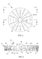
- Figures 1 through 4 represent a forging die 10 made up of an assembly of individual components, including a backplate 12 and segments 14 arranged in a radial pattern about a central region 16 of the backplate 12.
- the surfaces 20 and 22 of the segments 14 and central region 16, respectively, cooperate to define an interface surface 18 with which material forged by the die 10 is deformed.
- the surface 22 of the central region 16 is substantially flush with the surrounding surfaces 20 of the individual segments 14, though it is foreseeable that these surfaces 20 and 22 might not be coplanar.
- the segments 14 are seen in Figure 1 as being essentially identical in size and having essentially identical wedge shapes, though different sizes and shapes are also within the scope of the invention.
- each segment 14 is shown as abutting the central region 16, while the radially outermost extent of each segment 14 is shown as coinciding with the radially outermost extent of the backplate 12.
- a radial gap 32 exists between the adjacent radial edges of each adjacent pair of segments 14.
- the segments 14 are coupled to the backplate 12 but adapted for radial movement relative to the backplate 12 as a result of the backplate 12 and segments 14 having complementary guide features.
- the surface 24 of the backplate 12 facing the segments 14 has radially-oriented rails or splines 26 that extend between the central region 16 and perimeter of the backplate 12.
- the splines 26 can be integrally-formed raised features on the surface 24 of the backplate 12, or separately manufactured and installed on the backplate 12.
- the splines 26 are sized and shaped to be individually received in grooves 28 defined in the backside 30 of each segment 14.
- the splines 26 and grooves 28 are shown as having complementary-shaped dovetail cross-sections that prevent the segments 14 from being removed from the backplate 12 in a direction normal to the surface 24 of the backplate 12, yet permit free radial movement of the segments 14 on the backplate 12 such that the splines 26 serve as radial guides for the segments 14. While dovetail cross-sections are shown for the splines 26 and grooves 28, other interlocking cross-sections could also be used and are within the scope of this invention.
- the backplate 12 is also preferably constructed of individual components in the form of concentric bands 34 surrounding the central region 16 of the backplate 12.
- the bands 34 are secured together by radial pins 36 inserted through holes in the outermost band 34, through aligned holes in the inner band(s) 34, and into the central region 16 of the backplate 12.
- each of the bands 34 is represented as having an annular or ring shape, other shapes are also within the scope of the invention.
- each band 34 is preferably manufactured or otherwise equipped to carry a portion of each spline 26, and proper circumferential alignment of the bands 34 results in individual aligned splines 26, each made up of the spline portions on the bands 34.
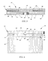
- the segments 14 are free to move in the radial direction (relative to the region 16) to coincide with and accommodate the radial motion of a material being deformed during a forging process in which the die 10 is used.
- a material such as a billet (40 in Figure 4 )
- radially outward flow of the deformed material is automatically assisted by the simultaneous radially outward travel of the segments 12, with the result that the incidence of cracking of the forging can be reduced by promoting - instead of frictionally inhibiting - radial growth of the billet material during forging.
- the concentric bands 34 of the backplate 12 can be added and removed as necessary to accommodate the increasing size of the forging.
- Multiple sets of segments 14 can be provided to match the different diameters of the backplate 12 achieved by varying the number of bands 34.
- the forging die 10 is not limited to installation on any particular type of forging ram, but is generally intended to be adapted for installation on a wide variety of forging equipment.
- the forging die 10 is first assembled to contain the desired number of bands 34 for the backplate 12 and segments 14 of appropriate number and size for the particular material to be forged.
- suitable materials for the backplate 12 and segments 14 include conventional tool steels and nickel alloys for improved durability, though other materials are also possible.
- tool steels and nickel alloys are both suitable as materials for the backplate 12 and segments 14.
- Billets suitable for forging a turbine disk can be produced according to various known practices.
- the starting powder material can be produced from a melt whose chemistry is that of the desired alloy. This step is typically accomplished by VIM processing, but could also be performed by adaptation of ESR or VAR processes.
- the alloy is converted into powder by atomization or another suitable process to produce generally spherical powder particles.
- the powder is then placed and sealed in a can, such as a mild steel can, whose size will meet the billet size requirement after consolidation. Thereafter, the can and its contents are consolidated at a temperature, time, and pressure sufficient to produce a dense consolidated billet 40. Consolidation can be accomplished by hot isostatic pressing (HIP), extrusion, or another suitable consolidation method.
- HIP hot isostatic pressing
- the interface surface 18 of the die 10 is preferably lubricated with a high temperature lubricant, such as a glass slurry of a type known in the art, for example, a slurry containing molybdenum disulfide (MoS 2 ), to promote sliding between the interface surface 18 and the billet 40.
- a high temperature lubricant such as a glass slurry of a type known in the art, for example, a slurry containing molybdenum disulfide (MoS 2 ), to promote sliding between the interface surface 18 and the billet 40.
- MoS 2 molybdenum disulfide
- the same or different lubricant may also be applied between the splines 26 and grooves 28 to facilitate movement of the segments 14 on the backplate 12.
- the billet 40 can then be forged with the die 10 of this invention according to known procedures, such as those currently utilized to produce disk forgings for large industrial turbines, though possibly modified to take advantage of the radial movement of the segments 14 during each forging stage, as well as any adjustments to the size of the die 10 made possible by the concentric bands 34 of the backplate 12.
- the forging operation is preferably performed at temperatures and under loading conditions that allow complete filling of the finish forging die cavity, avoid fracture, and produce or retain a uniform desired grain size within the material.
- forging is typically performed under superplastic forming conditions to enable filling of the forging die cavity through the accumulation of high geometric strains.
Landscapes
- Engineering & Computer Science (AREA)
- Mechanical Engineering (AREA)
- Forging (AREA)
- Turbine Rotor Nozzle Sealing (AREA)
- Powder Metallurgy (AREA)
Applications Claiming Priority (1)
| Application Number | Priority Date | Filing Date | Title |
|---|---|---|---|
| US11/856,111 US7805971B2 (en) | 2007-09-17 | 2007-09-17 | Forging die and process |
Publications (3)
| Publication Number | Publication Date |
|---|---|
| EP2036632A2 true EP2036632A2 (de) | 2009-03-18 |
| EP2036632A3 EP2036632A3 (de) | 2014-11-26 |
| EP2036632B1 EP2036632B1 (de) | 2016-06-01 |
Family
ID=40130540
Family Applications (1)
| Application Number | Title | Priority Date | Filing Date |
|---|---|---|---|
| EP08164009.6A Active EP2036632B1 (de) | 2007-09-17 | 2008-09-10 | Schmiedegesenk und Verfahren |
Country Status (4)
| Country | Link |
|---|---|
| US (1) | US7805971B2 (de) |
| EP (1) | EP2036632B1 (de) |
| JP (1) | JP5378734B2 (de) |
| CN (1) | CN101391278B (de) |
Cited By (2)
| Publication number | Priority date | Publication date | Assignee | Title |
|---|---|---|---|---|
| CN102019544A (zh) * | 2010-09-27 | 2011-04-20 | 江阴东大新材料研究院 | 特大型锻件铸焊锻复合成形方法 |
| EP2992978B1 (de) * | 2014-08-18 | 2016-10-19 | KAMAX Holding GmbH & Co. KG | Matrizenmodulsatz für presswerkzeuge zum herstellen von schrauben |
Families Citing this family (15)
| Publication number | Priority date | Publication date | Assignee | Title |
|---|---|---|---|---|
| US8230899B2 (en) * | 2010-02-05 | 2012-07-31 | Ati Properties, Inc. | Systems and methods for forming and processing alloy ingots |
| US9267184B2 (en) | 2010-02-05 | 2016-02-23 | Ati Properties, Inc. | Systems and methods for processing alloy ingots |
| CN101862807B (zh) * | 2010-06-11 | 2012-05-23 | 西安交通大学 | 一种大型盘类件的旋转锻造方法及锻造装置 |
| US10207312B2 (en) | 2010-06-14 | 2019-02-19 | Ati Properties Llc | Lubrication processes for enhanced forgeability |
| US20120051919A1 (en) * | 2010-08-31 | 2012-03-01 | General Electric Company | Powder compact rotor forging preform and forged powder compact turbine rotor and methods of making the same |
| US8789254B2 (en) | 2011-01-17 | 2014-07-29 | Ati Properties, Inc. | Modifying hot workability of metal alloys via surface coating |
| WO2013147154A1 (ja) | 2012-03-30 | 2013-10-03 | 日立金属株式会社 | 熱間鍛造用金型 |
| US9481932B2 (en) * | 2012-04-26 | 2016-11-01 | Cheung Woh Technologies Ltd. | Method and apparatus for progressively forging a hard disk drive base plate |
| US10245639B2 (en) * | 2012-07-31 | 2019-04-02 | United Technologies Corporation | Powder metallurgy method for making components |
| US9027374B2 (en) | 2013-03-15 | 2015-05-12 | Ati Properties, Inc. | Methods to improve hot workability of metal alloys |
| US9539636B2 (en) | 2013-03-15 | 2017-01-10 | Ati Properties Llc | Articles, systems, and methods for forging alloys |
| CN105448308B (zh) | 2014-08-27 | 2019-04-09 | 祥和科技有限公司 | 用于形成具有延长高度的硬盘驱动器基板的方法和装置 |
| EP3560622B1 (de) * | 2016-12-21 | 2021-11-10 | Hitachi Metals, Ltd. | Verfahren zur herstellung von warmgeschmiedetem material |
| PL443627A1 (pl) * | 2023-01-30 | 2024-08-05 | Schraner Polska Spółka Z Ograniczoną Odpowiedzialnością | Matryce do produkcji precyzyjnych odkuwek małogabarytowych i sposób ich wytwarzania, odkuwka otrzymana tym sposobem |
| CN119387486B (zh) * | 2024-11-12 | 2025-10-03 | 重庆大学 | 一种超大型复杂涡轮盘锻件精密化成形方法及模具 |
Family Cites Families (12)
| Publication number | Priority date | Publication date | Assignee | Title |
|---|---|---|---|---|
| US2754576A (en) * | 1952-01-30 | 1956-07-17 | Kropp Forge Company | Fabrication of forged brake band and the like |
| FR1298452A (fr) * | 1961-05-31 | 1962-07-13 | Commissariat Energie Atomique | Perfectionnements apportés aux procédés et appareils de forgeage à chaud, notamment pour la formation d'une gorge de sertissage |
| JPS5096635U (de) * | 1974-01-08 | 1975-08-12 | ||
| CH621952A5 (de) * | 1977-09-01 | 1981-03-13 | Bbc Brown Boveri & Cie | |
| JPS58187221A (ja) * | 1982-04-26 | 1983-11-01 | Daido Steel Co Ltd | 孔あけ装置 |
| JPH0613136B2 (ja) * | 1989-05-18 | 1994-02-23 | 工業技術院長 | セラミックス製恒温鍛造型 |
| JP2723343B2 (ja) * | 1990-06-26 | 1998-03-09 | 株式会社神戸製鋼所 | Ni基超合金製品の恒温鍛造方法 |
| US6484552B1 (en) * | 2000-12-16 | 2002-11-26 | Eaton Aeroquip, Inc. | Hinged die cage assembly |
| US6531002B1 (en) * | 2001-04-24 | 2003-03-11 | General Electric Company | Nickel-base superalloys and articles formed therefrom |
| US6688154B2 (en) * | 2001-07-19 | 2004-02-10 | Showa Denko Kabushiki Kaisha | Die for forging rotor, forge production system and forging method using the die, and rotor |
| DE10318060A1 (de) * | 2003-04-17 | 2004-11-18 | Eckold Gmbh & Co Kg | Matrize für einen Werkzeugsatz zum mechanischen Fügen |
| CN100361762C (zh) * | 2005-07-29 | 2008-01-16 | 中国科学院金属研究所 | 一种镁合金手机外壳的温热成形方法 |
-
2007
- 2007-09-17 US US11/856,111 patent/US7805971B2/en active Active
-
2008
- 2008-09-10 EP EP08164009.6A patent/EP2036632B1/de active Active
- 2008-09-12 JP JP2008234141A patent/JP5378734B2/ja active Active
- 2008-09-17 CN CN200810168006.4A patent/CN101391278B/zh not_active Expired - Fee Related
Cited By (3)
| Publication number | Priority date | Publication date | Assignee | Title |
|---|---|---|---|---|
| CN102019544A (zh) * | 2010-09-27 | 2011-04-20 | 江阴东大新材料研究院 | 特大型锻件铸焊锻复合成形方法 |
| CN102019544B (zh) * | 2010-09-27 | 2012-06-20 | 江阴东大新材料研究院 | 特大型锻件铸焊锻复合成形方法 |
| EP2992978B1 (de) * | 2014-08-18 | 2016-10-19 | KAMAX Holding GmbH & Co. KG | Matrizenmodulsatz für presswerkzeuge zum herstellen von schrauben |
Also Published As
| Publication number | Publication date |
|---|---|
| JP2009066661A (ja) | 2009-04-02 |
| US20090133462A1 (en) | 2009-05-28 |
| US7805971B2 (en) | 2010-10-05 |
| CN101391278B (zh) | 2013-07-31 |
| CN101391278A (zh) | 2009-03-25 |
| JP5378734B2 (ja) | 2013-12-25 |
| EP2036632B1 (de) | 2016-06-01 |
| EP2036632A3 (de) | 2014-11-26 |
Similar Documents
| Publication | Publication Date | Title |
|---|---|---|
| EP2036632B1 (de) | Schmiedegesenk und Verfahren | |
| JP5780728B2 (ja) | 多元合金ローターセクション、それを含む溶接されたタービンローター及びその製造方法 | |
| US6240765B1 (en) | Closed-die forging process and rotationally incremental forging press | |
| US4536932A (en) | Method for eliminating low cycle fatigue cracking in integrally bladed disks | |
| US5113583A (en) | Integrally bladed rotor fabrication | |
| EP2353750B1 (de) | Schweiß- und Schmiedverfahren zum Herstellen eines Komponentes | |
| EP3682982A1 (de) | Verfahren zur herstellung eines grossen ringförmigen schmiedestückes | |
| EP2520395A2 (de) | Komponenten und Verfahren zur Herstellung von Komponenten mit Regionen mit unterschiedlicher Kornstruktur | |
| US20130156558A1 (en) | Annular gas turbine engine case and method of manufacturing | |
| CN105050749A (zh) | 环轧用材料的制造方法 | |
| JP2011255409A (ja) | 環状成形体の製造方法 | |
| CN107206469A (zh) | 环状成型体的制造方法 | |
| JP2558858B2 (ja) | 中空部材の鍛造装置及びその方法 | |
| US3866303A (en) | Method of making cross-rolled powder metal discs | |
| CA2602994C (en) | Annular gas turbine engine case and method of manufacturing | |
| JP5795838B2 (ja) | リング状成形体の製造方法 | |
| EP0846505A2 (de) | Verfahren zum Schmieden mit geschlossenen Gesenk und Rotations-Schmiedepresse | |
| Wright et al. | Forging of blades for gas turbines | |
| JP6410135B2 (ja) | 熱間鍛造用金型 | |
| US20070092394A1 (en) | Supersolvus hot isostatic pressing and ring rolling of hollow powder forms | |
| US8177516B2 (en) | Shaped rotor wheel capable of carrying multiple blade stages | |
| WO1990002479A2 (en) | Dual-alloy disk system | |
| US20080086881A1 (en) | Annular gas turbine engine case and method of manufacturing | |
| JP7761086B1 (ja) | 熱間鍛造品の製造方法 | |
| RU191479U1 (ru) | Заготовка диска газотурбинного двигателя из жаропрочного сплава |
Legal Events
| Date | Code | Title | Description |
|---|---|---|---|
| PUAI | Public reference made under article 153(3) epc to a published international application that has entered the european phase |
Free format text: ORIGINAL CODE: 0009012 |
|
| AK | Designated contracting states |
Kind code of ref document: A2 Designated state(s): AT BE BG CH CY CZ DE DK EE ES FI FR GB GR HR HU IE IS IT LI LT LU LV MC MT NL NO PL PT RO SE SI SK TR |
|
| AX | Request for extension of the european patent |
Extension state: AL BA MK RS |
|
| PUAL | Search report despatched |
Free format text: ORIGINAL CODE: 0009013 |
|
| AK | Designated contracting states |
Kind code of ref document: A3 Designated state(s): AT BE BG CH CY CZ DE DK EE ES FI FR GB GR HR HU IE IS IT LI LT LU LV MC MT NL NO PL PT RO SE SI SK TR |
|
| AX | Request for extension of the european patent |
Extension state: AL BA MK RS |
|
| RIC1 | Information provided on ipc code assigned before grant |
Ipc: B21J 13/02 20060101ALI20141017BHEP Ipc: B21J 5/00 20060101AFI20141017BHEP |
|
| 17P | Request for examination filed |
Effective date: 20150526 |
|
| RBV | Designated contracting states (corrected) |
Designated state(s): AT BE BG CH CY CZ DE DK EE ES FI FR GB GR HR HU IE IS IT LI LT LU LV MC MT NL NO PL PT RO SE SI SK TR |
|
| AKX | Designation fees paid |
Designated state(s): CH DE FR GB LI |
|
| AXX | Extension fees paid |
Extension state: MK Extension state: RS Extension state: AL Extension state: BA |
|
| GRAP | Despatch of communication of intention to grant a patent |
Free format text: ORIGINAL CODE: EPIDOSNIGR1 |
|
| INTG | Intention to grant announced |
Effective date: 20160225 |
|
| GRAS | Grant fee paid |
Free format text: ORIGINAL CODE: EPIDOSNIGR3 |
|
| GRAA | (expected) grant |
Free format text: ORIGINAL CODE: 0009210 |
|
| AK | Designated contracting states |
Kind code of ref document: B1 Designated state(s): CH DE FR GB LI |
|
| REG | Reference to a national code |
Ref country code: GB Ref legal event code: FG4D |
|
| REG | Reference to a national code |
Ref country code: CH Ref legal event code: EP |
|
| REG | Reference to a national code |
Ref country code: DE Ref legal event code: R096 Ref document number: 602008044505 Country of ref document: DE |
|
| REG | Reference to a national code |
Ref country code: FR Ref legal event code: PLFP Year of fee payment: 9 |
|
| REG | Reference to a national code |
Ref country code: DE Ref legal event code: R097 Ref document number: 602008044505 Country of ref document: DE |
|
| PLBE | No opposition filed within time limit |
Free format text: ORIGINAL CODE: 0009261 |
|
| STAA | Information on the status of an ep patent application or granted ep patent |
Free format text: STATUS: NO OPPOSITION FILED WITHIN TIME LIMIT |
|
| 26N | No opposition filed |
Effective date: 20170302 |
|
| REG | Reference to a national code |
Ref country code: FR Ref legal event code: PLFP Year of fee payment: 10 |
|
| REG | Reference to a national code |
Ref country code: FR Ref legal event code: PLFP Year of fee payment: 11 |
|
| PGFP | Annual fee paid to national office [announced via postgrant information from national office to epo] |
Ref country code: GB Payment date: 20210820 Year of fee payment: 14 Ref country code: CH Payment date: 20210818 Year of fee payment: 14 Ref country code: DE Payment date: 20210818 Year of fee payment: 14 |
|
| REG | Reference to a national code |
Ref country code: DE Ref legal event code: R119 Ref document number: 602008044505 Country of ref document: DE |
|
| REG | Reference to a national code |
Ref country code: CH Ref legal event code: PL |
|
| GBPC | Gb: european patent ceased through non-payment of renewal fee |
Effective date: 20220910 |
|
| PG25 | Lapsed in a contracting state [announced via postgrant information from national office to epo] |
Ref country code: LI Free format text: LAPSE BECAUSE OF NON-PAYMENT OF DUE FEES Effective date: 20220930 Ref country code: DE Free format text: LAPSE BECAUSE OF NON-PAYMENT OF DUE FEES Effective date: 20230401 Ref country code: CH Free format text: LAPSE BECAUSE OF NON-PAYMENT OF DUE FEES Effective date: 20220930 |
|
| PG25 | Lapsed in a contracting state [announced via postgrant information from national office to epo] |
Ref country code: GB Free format text: LAPSE BECAUSE OF NON-PAYMENT OF DUE FEES Effective date: 20220910 |
|
| PGFP | Annual fee paid to national office [announced via postgrant information from national office to epo] |
Ref country code: FR Payment date: 20250821 Year of fee payment: 18 |