EP2036486A1 - Rehabilitationssystem für neurologische Erkrankungen - Google Patents
Rehabilitationssystem für neurologische Erkrankungen Download PDFInfo
- Publication number
- EP2036486A1 EP2036486A1 EP07116315A EP07116315A EP2036486A1 EP 2036486 A1 EP2036486 A1 EP 2036486A1 EP 07116315 A EP07116315 A EP 07116315A EP 07116315 A EP07116315 A EP 07116315A EP 2036486 A1 EP2036486 A1 EP 2036486A1
- Authority
- EP
- European Patent Office
- Prior art keywords
- signals
- patient
- rehabilitation
- stimulation
- vector
- Prior art date
- Legal status (The legal status is an assumption and is not a legal conclusion. Google has not performed a legal analysis and makes no representation as to the accuracy of the status listed.)
- Granted
Links
- 208000012902 Nervous system disease Diseases 0.000 title claims abstract description 6
- 208000025966 Neurological disease Diseases 0.000 title claims abstract description 6
- 230000000638 stimulation Effects 0.000 claims abstract description 22
- 238000005259 measurement Methods 0.000 claims abstract description 21
- 230000008859 change Effects 0.000 claims abstract description 12
- 230000001953 sensory effect Effects 0.000 claims abstract description 11
- 230000006872 improvement Effects 0.000 claims abstract description 9
- 208000027418 Wounds and injury Diseases 0.000 claims abstract description 5
- 208000014674 injury Diseases 0.000 claims abstract description 5
- 230000006378 damage Effects 0.000 claims abstract description 4
- 239000013598 vector Substances 0.000 claims description 35
- QVGXLLKOCUKJST-UHFFFAOYSA-N atomic oxygen Chemical compound [O] QVGXLLKOCUKJST-UHFFFAOYSA-N 0.000 claims description 6
- 229910052760 oxygen Inorganic materials 0.000 claims description 6
- 239000001301 oxygen Substances 0.000 claims description 6
- 230000036760 body temperature Effects 0.000 claims description 4
- 230000029058 respiratory gaseous exchange Effects 0.000 claims description 4
- 230000000763 evoking effect Effects 0.000 claims description 3
- 230000035487 diastolic blood pressure Effects 0.000 claims description 2
- 230000035488 systolic blood pressure Effects 0.000 claims description 2
- 230000036626 alertness Effects 0.000 abstract description 35
- 238000011217 control strategy Methods 0.000 description 17
- 230000036772 blood pressure Effects 0.000 description 14
- 230000003044 adaptive effect Effects 0.000 description 13
- 238000000034 method Methods 0.000 description 13
- 230000008569 process Effects 0.000 description 11
- 230000007423 decrease Effects 0.000 description 10
- 230000001965 increasing effect Effects 0.000 description 9
- 231100000430 skin reaction Toxicity 0.000 description 9
- 238000013528 artificial neural network Methods 0.000 description 8
- 230000006870 function Effects 0.000 description 8
- 238000001228 spectrum Methods 0.000 description 8
- 238000002474 experimental method Methods 0.000 description 7
- 230000004044 response Effects 0.000 description 7
- 238000012706 support-vector machine Methods 0.000 description 6
- 238000013459 approach Methods 0.000 description 5
- 230000006399 behavior Effects 0.000 description 5
- 230000002596 correlated effect Effects 0.000 description 5
- 230000004424 eye movement Effects 0.000 description 5
- 210000000748 cardiovascular system Anatomy 0.000 description 4
- 230000003247 decreasing effect Effects 0.000 description 4
- 238000013178 mathematical model Methods 0.000 description 4
- 230000009471 action Effects 0.000 description 3
- 230000006978 adaptation Effects 0.000 description 3
- 230000002526 effect on cardiovascular system Effects 0.000 description 3
- 230000000694 effects Effects 0.000 description 3
- 239000000203 mixture Substances 0.000 description 3
- 230000011514 reflex Effects 0.000 description 3
- 230000000241 respiratory effect Effects 0.000 description 3
- 238000012549 training Methods 0.000 description 3
- 206010005746 Blood pressure fluctuation Diseases 0.000 description 2
- 206010010071 Coma Diseases 0.000 description 2
- 230000033228 biological regulation Effects 0.000 description 2
- 210000004556 brain Anatomy 0.000 description 2
- 238000004422 calculation algorithm Methods 0.000 description 2
- 230000000747 cardiac effect Effects 0.000 description 2
- 238000006243 chemical reaction Methods 0.000 description 2
- 230000001419 dependent effect Effects 0.000 description 2
- 230000003993 interaction Effects 0.000 description 2
- 230000007246 mechanism Effects 0.000 description 2
- 230000004048 modification Effects 0.000 description 2
- 238000012986 modification Methods 0.000 description 2
- 230000001537 neural effect Effects 0.000 description 2
- 230000036581 peripheral resistance Effects 0.000 description 2
- 230000035790 physiological processes and functions Effects 0.000 description 2
- 238000012545 processing Methods 0.000 description 2
- 230000036391 respiratory frequency Effects 0.000 description 2
- 230000037046 slow wave activity Effects 0.000 description 2
- 230000003068 static effect Effects 0.000 description 2
- 230000000007 visual effect Effects 0.000 description 2
- 206010019196 Head injury Diseases 0.000 description 1
- 206010061225 Limb injury Diseases 0.000 description 1
- 230000037007 arousal Effects 0.000 description 1
- 230000008901 benefit Effects 0.000 description 1
- 230000017531 blood circulation Effects 0.000 description 1
- 238000009530 blood pressure measurement Methods 0.000 description 1
- 210000004204 blood vessel Anatomy 0.000 description 1
- 230000007177 brain activity Effects 0.000 description 1
- 210000005013 brain tissue Anatomy 0.000 description 1
- 238000004364 calculation method Methods 0.000 description 1
- 230000003727 cerebral blood flow Effects 0.000 description 1
- 230000002490 cerebral effect Effects 0.000 description 1
- 230000004087 circulation Effects 0.000 description 1
- 238000004891 communication Methods 0.000 description 1
- 238000005094 computer simulation Methods 0.000 description 1
- 238000001816 cooling Methods 0.000 description 1
- 230000000875 corresponding effect Effects 0.000 description 1
- 238000013016 damping Methods 0.000 description 1
- 238000009795 derivation Methods 0.000 description 1
- 238000005183 dynamical system Methods 0.000 description 1
- 238000011156 evaluation Methods 0.000 description 1
- 210000001061 forehead Anatomy 0.000 description 1
- 230000010247 heart contraction Effects 0.000 description 1
- 238000010438 heat treatment Methods 0.000 description 1
- 230000010365 information processing Effects 0.000 description 1
- 230000010354 integration Effects 0.000 description 1
- 238000011835 investigation Methods 0.000 description 1
- 230000007774 longterm Effects 0.000 description 1
- 239000011159 matrix material Substances 0.000 description 1
- 238000012806 monitoring device Methods 0.000 description 1
- 238000012544 monitoring process Methods 0.000 description 1
- 210000003205 muscle Anatomy 0.000 description 1
- 210000002569 neuron Anatomy 0.000 description 1
- 238000005312 nonlinear dynamic Methods 0.000 description 1
- 238000010606 normalization Methods 0.000 description 1
- 238000005457 optimization Methods 0.000 description 1
- 230000004962 physiological condition Effects 0.000 description 1
- 230000001902 propagating effect Effects 0.000 description 1
- 238000011084 recovery Methods 0.000 description 1
- 230000000306 recurrent effect Effects 0.000 description 1
- 230000001105 regulatory effect Effects 0.000 description 1
- 210000002345 respiratory system Anatomy 0.000 description 1
- 238000012552 review Methods 0.000 description 1
- 238000007493 shaping process Methods 0.000 description 1
- 238000010183 spectrum analysis Methods 0.000 description 1
- 230000000153 supplemental effect Effects 0.000 description 1
- 238000012360 testing method Methods 0.000 description 1
- 230000001960 triggered effect Effects 0.000 description 1
- 230000008016 vaporization Effects 0.000 description 1
- 238000009834 vaporization Methods 0.000 description 1
- 230000006442 vascular tone Effects 0.000 description 1
Images


Classifications
-
- A—HUMAN NECESSITIES
- A61—MEDICAL OR VETERINARY SCIENCE; HYGIENE
- A61H—PHYSICAL THERAPY APPARATUS, e.g. DEVICES FOR LOCATING OR STIMULATING REFLEX POINTS IN THE BODY; ARTIFICIAL RESPIRATION; MASSAGE; BATHING DEVICES FOR SPECIAL THERAPEUTIC OR HYGIENIC PURPOSES OR SPECIFIC PARTS OF THE BODY
- A61H1/00—Apparatus for passive exercising; Vibrating apparatus; Chiropractic devices, e.g. body impacting devices, external devices for briefly extending or aligning unbroken bones
-
- A—HUMAN NECESSITIES
- A61—MEDICAL OR VETERINARY SCIENCE; HYGIENE
- A61B—DIAGNOSIS; SURGERY; IDENTIFICATION
- A61B5/00—Measuring for diagnostic purposes; Identification of persons
- A61B5/24—Detecting, measuring or recording bioelectric or biomagnetic signals of the body or parts thereof
- A61B5/316—Modalities, i.e. specific diagnostic methods
- A61B5/369—Electroencephalography [EEG]
- A61B5/375—Electroencephalography [EEG] using biofeedback
-
- A—HUMAN NECESSITIES
- A61—MEDICAL OR VETERINARY SCIENCE; HYGIENE
- A61B—DIAGNOSIS; SURGERY; IDENTIFICATION
- A61B5/00—Measuring for diagnostic purposes; Identification of persons
- A61B5/48—Other medical applications
- A61B5/486—Bio-feedback
-
- A—HUMAN NECESSITIES
- A61—MEDICAL OR VETERINARY SCIENCE; HYGIENE
- A61H—PHYSICAL THERAPY APPARATUS, e.g. DEVICES FOR LOCATING OR STIMULATING REFLEX POINTS IN THE BODY; ARTIFICIAL RESPIRATION; MASSAGE; BATHING DEVICES FOR SPECIAL THERAPEUTIC OR HYGIENIC PURPOSES OR SPECIFIC PARTS OF THE BODY
- A61H2230/00—Measuring physical parameters of the user
- A61H2230/08—Other bio-electrical signals
Definitions
- the invention relates to a rehabilitation system for neurological disorders, especially a system for the rehabilitation of patients being in a vegetative state or minimal conscious state.
- WO 01/36051 describes a motor learning system for rehabilitation of neurological disorders and especially to orthopaedic limb injuries.
- Said device comprises an insole or pad including a pressure sensor and/or force sensor to measure the weight force applied to at least two monitored locations of at least one limb of a patient.
- the sensors are connected to a computer processor making a comparison of the determined weight values against a predefined target weight distribution. Said target weight distribution is based on parameters unique to the patient and the injury.
- the processor is adapted to drive a stimulator delivering closed-loop sensory stimulation as feedback to encourage the patient to distribute said weight more evenly.
- the sensory stimulation can comprise visual and/or audio effects as well as mechanical vibrations.
- Such a device is adapted to be used by a patient being able to actively follow the program defined through application of said target parameters and which patient decides about his actions.
- the aim of the device is to help a patient to find the equal weight distribution.
- static inputs as e.g. gender and biomechanical properties of the fixation of the injury and quasi-static inputs as e.g. time post-injury and weight
- a initial rehabilitation program is generated, including e.g. bandwidth range and frequency of the walking patient.
- the patient receives said feedback information to improve his performance.
- the data set of acquired information is compared to the predefined success criteria and the initial rehabilitation program is adapted to better suit the needs of the patient for a following session.
- Said system is not suitable for patients in a vegetative state or minimal conscious state.
- the known device initially generates predefined target signals determined and based on input parameters and then delivers - during a rehabilitation session - sensory stimulation to the patient as feedback based on a comparison of the measurement signals with target signals. Only after one completed rehabilitation session the predefined target signals for a subsequent rehabilitation session are adapted following the result of the completed rehabilitation session.
- the invention is based on the insight that the adoption of the sensory answer of the system has preferably to be adapted during a session.
- the invention uses preferably at least two different physiological parameters and two different physiological signals retrieved by sensors to control the output of preferably at least two different displays.
- the system can hop to a different 'initial' parameter set. For this a time interval is defined and the change of the initial measurement signals to the current measurement signals is compared to said improvement threshold value or vector. If the improvement does not reach a predefined threshold value or vector the one or more of the stimulation generators delivering sensory stimulation to the patient as feedback are reset to follow new predefined target signals.
- Fig. 1 to 8 show rehabilitation devices encompassing - inter alia - different controller strategies. Similar features in all embodiments receive the same reference signs and are usually only described in detail in the first described embodiment in which they appear.
- Fig. 1 shows a rehabilitation device according to a first embodiment of the invention using an open-loop/feedforward control.
- the rehabilitation device comprises a interpreter computer unit 10 named parameter database in Fig. 1 .
- This unit 10 comprises input and output facilities.
- the arrow L a relates to a vector called 'level of alertness' which is to be defined as a set of parameters.
- the same set of parameters describes the 'actual level of alertness' L out , i.e. comprising the same vector elements.
- These elements are physiological quantities.
- Such physiological quantities can be chosen from the group encompassing e.g. EEG signals and Evoked Potentials, EMG signals, heart rate, systolic and diastolic blood pressure, respiration frequency, skin conductance, oxygen saturation, body temperature, etc..
- physiological quantities are measurement signals which can be acquired through sensors 20, which are applied to a patient 30. Additionally, of course, the sensors 20 also receive noise and interference signals, which preferably are filtered at least in the computer 10. The signals O se will be acquired by means of sensors and electrodes 20 to measure non-electrical and bioelectrical physiological signals, respectively.
- the database of parameters of computer 10 can also be called to be an interpreter, since this database is filled and identified on the basis of objective parameters retrieved through experimental investigations, and subjective fixation of alertness conditions based on literature reviews and knowledge of experienced medical doctors.
- the reference vector with predicted values O d will be the input to an inverse dynamic model 40 describing the physiological processes of the patient.
- the model 40 determines the required input signals I m fed to the display devices 50 (feedforward loop).
- the interpreter computer 10 sends signals S to drive display modes and switch on/off display devices.
- the control can be described as an array to image the input vector onto a selected output vector.
- Models 40 are known from the prior art, e.g. Timischl, S. "A Global Model for the Cardiovascular and Respiratory System” published as PhD thesis, Karl-Franzens University of Graz, August 1998. Another model is focused on the analysis of slow dynamical variations of long term neurophysiological parameters like the partial oxygen pressure of brain tissue or the cerebral blood flow, disclosed by Jung et al. "A mathematical model of cerebral circulation and oxygen supply”.
- Display device Example leg or arm movement generator a stepper like dis- closed in WO00/61059 tilting board/bench for body verticalisation a tilting table like disclosed in WO00/61059 graphical display a monitor acoustic display loud speakers, head-phones tactile stimulator a vibrator unit olfactory display Via odour vaporization heat or cold display IR lamp for heating or peltier element for cooling
- the patient will show a physiological output O on the display 50 and can react with an interaction O i to the display 50.
- Such an interaction can be a reflex or a change of a subconscious physiological condition.
- Such a change can occur fast (in seconds) as in case of the heart rate or slowly (in minutes) as in case of some EEG patterns.
- the system can hop to a different 'initial' parameter set, i.e. to apply different stimulation values or simply different stimulation, i.e. it is possible to initially use an acoustic display and after several minutes the acoustic display is changed or replaced by or added to a graphical display. For this a time interval is defined and the change of the initial measurement signals to the current measurement signals is compared to said improvement threshold value or vector. If the improvement does not reach a predefined threshold value or vector within the responses, e.g. eye movement, heart rate change etc., the one or more of the stimulation generators delivering sensory stimulation to the patient as feedback are reset to follow new predefined target signals. Usually the same already applied sensors 20 are continuously acquiring the same measurement signals.
- Fig. 2 shows a rehabilitation device according to a second embodiment of the invention using a feedback control.
- the system uses identical units 10, 20, 30, 40 and 50.
- the inverse model of the patient of Fig. 1 is adapted to become the so called awakening controller 42.
- In the feedback loop recorded signals O se will be compared to the reference values O d and the error fed into the (awakening) controller 42.
- the controller 42 determines the required input signals I ac inducted to the display devices 50.
- Fig. 3 shows a rehabilitation device according to a third embodiment of the invention using a combination of feedforward and feedback control. Therefore the awakening controller unit 41 comprises beside the inverse model 40 the controller 42 from Fig. 2 .
- the predicted error vector I e is calculated by controller 42 which receives the input signals as in Fig. 2 .
- the predicted error vector I e and the output I m of the inverse human model 41 will sum up and define the input I ac to the multi-modal display 50.
- the display 50 will expose the patient to the defined sensory modalities I .
- Fig. 4 shows a rehabilitation device according to a fourth embodiment of the invention using the combined control strategy according to Fig. 3 with safety extension.
- the physiological values retrieved by the sensors 20 will be checked via a monitoring device 60.
- a monitoring device 60 Defined thresholds will influence the actuation and drive of the display 50 (e.g. movement generator, tilting board, acoustic display) in a safe mode.
- the display 50 e.g. movement generator, tilting board, acoustic display
- the inclination angle s ⁇ of a tilting board will decrease for some degrees or back to zero.
- Fig. 5 shows a rehabilitation device according to a fifth embodiment of the invention using the combined control strategy according to Fig. 3 with additional input 21 for the model 40. Additional to the controller 42 the inverse dynamic model 40 will get a feedback of the real measured physiological values through line 21. The information will be used to adjust I m individually to the situation of the treated patient.
- Fig. 5 does not show a safety extension unit 60
- the different descriptions of different embodiments in connection with Fig. 1 to 8 and their application and actual use in connection with Fig. 9 to 15 does not mean, that they have to be seen isolated one-by-one, but that the invention also comprises the combination of the features shown, i.e. someone skilled in the art will apply a safety extension 60 as disclosed in connection with Fig. 4 to a device according to one of Fig. 1, 2 or 5 and subsequent Fig. as well as the additional feedback line 21 can also be incorporated in various embodiments, as for example in embodiments according to Fig. 1, 3 or 4 .
- Fig. 6 shows a rehabilitation device according to a sixth embodiment of the invention using the combined control strategy according to Fig. 3 with additional adaptive extension input 22 for the model 40 and the controller 41.
- the main difference to the previous control strategies is the adaptive part 22, 23.
- the two parts of the awakening controller 41 i.e. the inverse model 40 and controller 42 will be adapted during the training with signal paths 22 and 23, respectively.
- This relates to a direct sensor input into the inverse model 40 and the controller 42 additionally to the feedback with inclusion of parameters based on and stored in the parameter database unit 10.
- Fig. 7 shows a rehabilitation device according to a seventh embodiment of the invention using the combined control strategy according to Fig. 3 with additional adaptive extension input 24 for the interpreter computer unit 10.
- the adjustment will be driven by the error between the defined level of alertness L a and the actual level of alertness L out .
- Fig. 8 shows a rehabilitation device according to a eighth embodiment of the invention using the control strategy according to Fig. 1 using a direct model 70 with additional adaptive input paths 25 and 26 for the direct model 70 and the indirect model 40, respectively.
- the inverse dynamic model 40 delivers the predicted input values for the multi-modal display 50 and the direct dynamic model 70 of the patient 30.
- the direct and the inverse dynamic model are identical except that they are 'reversed' with respect to each other.
- the direct dynamic model is an 'observer' of the reaction to the exposed stimuli.
- the error between the physiological output signals O m predicted by the direct dynamic model and the recorded outcome O se will drive the adaptation mechanism 80 issuing the signals on the paths 25 and 26.
- the direct feedback come in addition to the input of the database 10 in a way similar to the embodiment according to Fig. 6 .
- controllers 10, 42 can be chosen to build the controllers 10, 42 as well as controllers 40 and 70.
- controllers 40 and 70 Some examples will now be disclosed to illustrate the possibilities without limiting the scope of the invention. The examples are:
- a proportional-integral-derivative controller attempts to correct the error between measured process variables O se and desired setpoints O d . By calculating and then outputting a corrective action the process can be adjusted accordingly, based upon three parameters (proportional, integral and derivative values).
- the integral term permits the rejection of a step disturbance and the derivative term is used to provide damping or shaping of the response.
- the controller will be called a PI, PD, P or I controller in absence of respective control actions.
- Direct pole placement can be performed mathematically using a state space representation of the open-loop system and calculating a feedback matrix assigning poles in the desired positions, in view of the fact that the system to handle is a multi-input multi-output (MIMO) system.
- MIMO multi-input multi-output
- Model predictive controllers rely on dynamic models of the process, most often linear empirical models obtained by system identification. The models are used to predict the behaviour of the dependent variables I e (t) of a dynamical system with respect to changes in the process independent vectors O se and O d .
- the model predictive controller uses the models and current plant measurements to calculate future moves in the independent variables that will result in operation that honors all independent and dependent variables constraints.
- the MPC is a multivariable control algorithm that uses (1) an internal dynamic model of the process, (2) a history of past control moves (3) an optimization cost function over the prediction horizon, to calculate the optimum control moves.
- One example for the cost function can be to minimize the absolute value of the error O err .
- Adaptive control uses on-line identification of the process parameters, or modification of controller gains, thereby obtaining strong robustness properties.
- Intelligent control uses various computing approaches like Fuzzy Logic, Bayesian probability, support vector machines or artificial neural networks to control the dynamic system.
- a fuzzy control system is a control system based on Fuzzy Logic - a mathematical system that analyzes analogue input values (often rough or "fuzzy" qualitative information) in terms of logical variables that take on continuous values between 0 and 1. As an example you can think about the change of the heart rate. The heart rate can be static, slightly increased or decreased, medium increased or decreased and so on. All the input variables in a fuzzy control system are in general mapped into by sets of membership functions, also known as 'fuzzy sets', the basic requirement for the controller.
- Support vector machines are a set of related supervised learning methods used for classification and regression. They belong to a family of generalized linear classifiers. A special property of SVMs is that they simultaneously minimize the empirical classification error and maximize the geometric margin; hence they are also known as maximum margin classifiers.
- the input vectors are O se (t) and O d (t) but also derivations, integrations or correlations between single signals like galvanic skin response and body temperature or heart rate and oxygen saturation. All vectors that belong to the same state of alertness built a set of data points. Support vector machines map all input vectors (different sets of data points) to a higher dimensional space where a maximal separating hyperplane is constructed.
- SVMs are well known in recognition of speech, objects and gesture - here they are used to recognize the state of alertness.
- An artificial neural network is an interconnected group of artificial neurons that uses a mathematical model or computational model for information processing based on a connectionist approach to computation.
- ANN is an adaptive system that changes its structure based on external or internal information that flows through the network.
- the input vectors are again O se (t) and O d (t) and derived signals.
- the output vector of the controller is I e (t) .
- the word 'network' in the term 'artificial neural network' arises because the function f(x) is defined as a composition of other functions g i (x), which can further be defined as a composition of other functions. This can conveniently represented as a network structure, with arrows depicting the dependencies between variables.
- the heart rate is a function of blood pressure and the galvanic skin response signal.
- the blood pressure itself is also a function of the galvanic skin response signal, the resistance of the vessels and the respiration frequency. This is only the beginning of the whole network and a widely used type of composition is the nonlinear weighted sum.
- a lot of experimental data is required to train and validate the ANN controller: a subset of data will be used to train (teach) an 'empty' ANN and adapt its characteristics to optimally control the plant (patient) via the parameters of I e (t) . Another subset of data is used to validate (test) the controller.
- Vegetative and minimal conscious state patients can show a behaviour with strong non-linear dynamics.
- control theory it is sometimes possible to linearize such classes of systems and apply linear techniques: in our case with patients it is possible to devise control strategies of non-linear systems, especially the 'intelligent control strategies' can be combined with non-linear parts.
- the models are based on mathematical principles like artificial neural network, Fuzzy Logic or numerical approaches. Dynamic models are required as components within the control strategies in order to predict, observe, interpret, or control the behaviour of the plant (patient).
- Kappel F. and Peer, R.O. proposed "A mathematical model for fundamental regulation processes in the cardiovascular system” in Journal of Mathematical Biology, 6:611-631, 1993 .
- the article presented a mathematical model for the fundamental processes of the cardiovascular system. Further work on modelling was reported by Timischl (see above), who included also a respiratory model. Both models use a closed-loop feedback system regulating the cardiovascular system with optimal control theory.
- an extension was derived to describe some specific cardiovascular relationships while using a stepper like disclosed in a device as disclosed WO00/61059 .
- the inclination angle s ⁇ and the stepping frequencies s ste for performing the stepping patterns was chosen as an input of the model.
- the output includes heart rate (f HR ) and mean blood pressure (p m ).
- f HR heart rate
- p m mean blood pressure
- a non-linear model with linear, exponential and sigmoid-functions as well as 2 nd order differential equations was used.
- the identification of the model was done with a least-square algorithm.
- the output of the model as well as the measured output of a healthy person is shown in Fig. 9 and 10 .
- Fig. 9 shows the heart rate over time at various angles at two frequencies using a system according to an embodiment of the invention as seen in Fig. 3 or 4 .
- the output value is the heart rate; the triggers are ongoing in time: Trigger 1: Start leg drives 0.4Hz, Trigger 2: Tilt to 20°, Trigger 3: Tilt to 55°, Trigger 4: Tilt to 75°, Trigger 5: Stop leg movement, Trigger 6: Tilt to 0°.
- Fig. 10 shows the mean blood pressure over time at various angles at two frequencies using a system according to an embodiment of the invention as seen in Fig. 3 or 4 .
- the output value is the blood pressure; the triggers are ongoing in time: Trigger 1: Start leg drives 0.4Hz, Trigger 2: Tilt to 20°, Trigger 3: Tilt to 55°, Trigger 4: Tilt to 75°, Trigger 5: Stop leg movement, Trigger 6: Tilt to 0°.
- Fig. 11 shows pulse transit time (PTT) 91 and the inverted PTT values 92, blood pressure in [mmHg] and relative gradient of the PTT values for the same environment as explained in connection with Fig. 9 and 10 ;
- Trigger 1 Start of 0.8Hz active stepping
- Trigger 2 Tilt to 75°
- Trigger 3 Stop movement
- Trigger 4 Tilt to 0°.
- An alternative blood pressure determination is the time between the heart contraction (recorded with the ECG) and the arrival of the pulse wave at the extremity (detected with a piezo pulse sensor), the pulse transit time (PTT).
- the PTT is the time of the pulse wave propagating between two different sites in the arterial system. It is known from the art that the speed of the pulse wave is directly proportional to the blood pressure. Hence, if the blood pressure rises the arterial walls become stiffer and PTT decreases, and conversely, when blood pressure falls, vascular tone decreases and PTT increases. Therefore Fig. 11 shows the pulse transit times 91 and the inverted pulse transit times 92, being mirrored at approximately 70 mm HG.
- Fig. 11 a clear change in blood pressure can be seen.
- PTT decreases as the subject starts to move the legs actively. In upright posture and still in active movement, PTT stays constant and rises to a higher constant level when stopping the leg activity. After the return to 0° PTT decreases again.
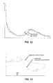
- Fig. 12 shows an EEG frequency power spectrum during the intervention using a system according to Fig. 3 . Additional to the cardiovascular relationship the changes in the EEG data can be verified and modelled. In Fig. 12 the distribution of the power spectrum vs. the frequency is shown. During a training (30 minutes) using a device as disclosed in WO00/61059 with a minimal conscious state patient the distribution of the power spectrum is changing. Comparing the power spectrum of the first 15 minutes to the last 15 minutes there is a shift of the distribution to lower frequencies (from the beta to the alpha frequency band).
- This information (out of the EEG signal) is also used by the controller.
- the main difference to other signals like ECG is the time delay.
- the calculation of the distribution of the power spectrum will take a few minutes while the response of the heart rate can be analyzed after a few seconds.
- the controller always tries to minimize the error between the real data and the desired ones. For the heart rate this process will take place every 10 seconds whereas for the EEG-signals it will take place every 3 minutes.
- the controller is adapted to control with quick response times based on a first measurement signal acquired based on a fast physiological signal as well as take into consideration slow changes of a slow physiological signal.
- a fast physiological signal is a signal allowing response times of seconds to under one minute, preferably under 30 seconds
- a slow physiological signal is a signal necessitating response times of at least one, preferably two minutes.
- the interpreter computer unit 10 is the 'logic'-part of the whole concept. Here the different stages of the 'levels of awareness' L a are determined.
- GCS Glasgow Coma Scale
- EFA Early Functional Abilities
- JFK Coma Recovery Scale - revised JFC CRS-r
- the interpreter computer unit and database 10 is based on the state-of-the-art or - in other words - the qualitative description of the patient's state of alertness/awareness.
- the experience and knowledge of the medical doctors about the behaviour of the patients as well as the knowledge represented in the literature form the basic fundament of the database.
- all the acquired physiological data is used to get a supplemental quantitative description of the states of alertness.
- the P300 is a neural evoked potential component of the electroencephalogram (EEG). This event-related potential appears as a positive deflection of the EEG voltage at approximately 300ms and is supposed to follow unexpected auditory stimuli. Latency and amplitude of the P300 signal can be used as an indicator for the state of alertness. A short latency is equivalent for a fast brain processing and, thus, for a high level of alertness. Due to the distinct variability among the subjects normalized parameters are helpful. The area between the normal graph and the deflection one ( figure 4.1 ) is used as one solution for that normalization issue.
- EEG electroencephalogram
- Fig. 13 shows two P300 graphs of a patient at the CPz-electrode of a 10-20 EEG system. Additionally, from the artefact-compensated EEG data subparameters can be extracted such as frequency band ratios. All the subparameters are fitted together in a set of weighted parameters. This affirms the statement about the level of alertness as mentioned above.
- the interpreter unit 10 decides which choice of input signals may lead to different levels of alertness.
- the interpreter unit 10 chooses a special subset of input signals or parameters, which are probably 'good' for an individual patient in the sense that they lead to an output of the sensors relating to a higher level of alertness.
- the advantage of the system according to the invention is the fact, that there is of course not only one optimal set of parameters for the vector of input parameters. There are a number of such subsets which all allow to reach 'local maxima' in the resulting measured multi-dimensional vector signal, in the sense that each sensor contributes one scalar value to the vector signal or that a subset of sensors contributes a subset of scalar values to the resulting vector signal representing an awareness level. For example the combination of a higher heart rate with characteristic galvanic skin response and a drift of the distribution of the brain activity towards the alpha frequency band is an expression for a high level of alertness shown in a three-dimensional vector.
- a first control step the input for the awakening controller tries to reach exactly this set of parameters by using the appropriate stimuli via the vector S and the multi-modal display 50 respectively, as shown in the drawings relating to the embodiments in Fig. 1 to 8 . If this strategy will not achieve a predefined satisfactory result, the set of parameters will be changed. In the next step the combination of a higher heart rate with characteristic galvanic skin response and a higher oxygen saturation should be reached. This second set of parameter stands also for a high level of alertness - the next 'local maximum'. All these stages and the corresponding sets of parameters as well as threshold of the decision relating to the choice of target vector S are part of the interpreter unit 10.
- the signal vector displaying a higher 'state of alertness' can be composed from a subset of the following single signals:
- the set of parameters of the interpreter computer unit 10 can use the direct correlation between some of the signals:
- the control strategy relates to an embodiment with the combination of the feedforward and feedback control as in Fig. 3 , wherein only the heart rate (HR) will be controlled by means of the inverse model and a P controller.
- the chosen display is the inclination angle for a device as disclosed in WO00/61059 .
- the individual range of the heart rate (HR) was determined. After laying 5 minutes in supine position, the inclination angle changes from 0° to 75°. For a baseline measurement the whole duration is 15 minutes and the stepping frequency has a constant value of 0.4Hz. For this subject the averaged 'low' heart rate is 62.5 bpm (beats per minute) and the 'high' one is 76 bpm at an inclination angle of 0° and 75°, respectively. These values are necessary to obtain the maximal range of the HR (related to the tilting angle) as well as to identify the dynamic inverse model 40.
- Fig. 14 shows that during the experiment, while the inclination angle changes from 0° to 75°, the average heart rate (shown as flat line 101) changes from 62.5 to 76 bpm; the stepping frequency is a constant value of 0.4Hz during the whole experiment.
- the investigator chooses a HR of 72 bpm (in the range of the low and high HR) as the desired one (HR d ).
- the desired value is the input of an inverse dynamic model describing the physiological process of the HR.
- the model determines the required angle ⁇ m and as a result the device is tilting the subject to this angle.
- the recorded signal (HR se ) is acquired by means of ECG electrodes.
- HR se is compared to the reference value HR d and the error fed into the P controller.
- the controller determines the required angle ⁇ e and provokes a modification of the tilting angle ⁇ tilt .
Landscapes
- Health & Medical Sciences (AREA)
- Life Sciences & Earth Sciences (AREA)
- Veterinary Medicine (AREA)
- Public Health (AREA)
- General Health & Medical Sciences (AREA)
- Animal Behavior & Ethology (AREA)
- Surgery (AREA)
- Engineering & Computer Science (AREA)
- Biomedical Technology (AREA)
- Heart & Thoracic Surgery (AREA)
- Medical Informatics (AREA)
- Molecular Biology (AREA)
- Pathology (AREA)
- Biophysics (AREA)
- Physics & Mathematics (AREA)
- Physical Education & Sports Medicine (AREA)
- Epidemiology (AREA)
- Pain & Pain Management (AREA)
- Rehabilitation Therapy (AREA)
- Biodiversity & Conservation Biology (AREA)
- Psychiatry (AREA)
- Psychology (AREA)
- Measurement And Recording Of Electrical Phenomena And Electrical Characteristics Of The Living Body (AREA)
- Measuring Pulse, Heart Rate, Blood Pressure Or Blood Flow (AREA)
- Rehabilitation Tools (AREA)
Priority Applications (2)
| Application Number | Priority Date | Filing Date | Title |
|---|---|---|---|
| EP07116315.8A EP2036486B1 (de) | 2007-09-13 | 2007-09-13 | Rehabilitationssystem für neurologische Erkrankungen |
| US12/209,649 US8905926B2 (en) | 2007-09-13 | 2008-09-12 | Rehabilitation system for neurological disorders |
Applications Claiming Priority (1)
| Application Number | Priority Date | Filing Date | Title |
|---|---|---|---|
| EP07116315.8A EP2036486B1 (de) | 2007-09-13 | 2007-09-13 | Rehabilitationssystem für neurologische Erkrankungen |
Related Child Applications (1)
| Application Number | Title | Priority Date | Filing Date |
|---|---|---|---|
| EP11182415 Division-Into | 2011-09-22 |
Publications (2)
| Publication Number | Publication Date |
|---|---|
| EP2036486A1 true EP2036486A1 (de) | 2009-03-18 |
| EP2036486B1 EP2036486B1 (de) | 2014-01-15 |
Family
ID=38920491
Family Applications (1)
| Application Number | Title | Priority Date | Filing Date |
|---|---|---|---|
| EP07116315.8A Not-in-force EP2036486B1 (de) | 2007-09-13 | 2007-09-13 | Rehabilitationssystem für neurologische Erkrankungen |
Country Status (2)
| Country | Link |
|---|---|
| US (1) | US8905926B2 (de) |
| EP (1) | EP2036486B1 (de) |
Cited By (6)
| Publication number | Priority date | Publication date | Assignee | Title |
|---|---|---|---|---|
| EP2227210A2 (de) | 2008-01-03 | 2010-09-15 | Clemens Gutknecht | Patientenbett mit überwachungs- und therapieeinrichtung |
| ES2351135A1 (es) * | 2010-04-14 | 2011-02-01 | Worldwide Integral Rehabilitation Systems, S.L | Sistema de valoracion, evaluacion y control de movimientos y acciones de usuarios que realizan ejercicios para la rehabilitacion fisica o neurologica. |
| CN102427766A (zh) * | 2009-03-20 | 2012-04-25 | 瓦洛里萨申-雷彻切有限合伙公司 | 用于测量轻度知觉损伤的设备和方法 |
| EP3127526A4 (de) * | 2014-04-04 | 2017-12-20 | Sapporo Medical University | Vorrichtung zur rehabilitation, rehabilitationssystem damit, programm zur rehabilitation und rehabilitationsverfahren |
| RU2697230C1 (ru) * | 2018-11-19 | 2019-08-13 | федеральное государственное бюджетное учреждение "Национальный медицинский исследовательский центр имени В.А. Алмазова" Министерства здравоохранения Российской Федерации | Способ прогнозирования восстановления сознания у пациентов в вегетативном состоянии нетравматического генеза на основе анализа динамики фоновой биоэлектрической активности мозга после применения золпидема |
| RU2746465C2 (ru) * | 2014-04-07 | 2021-04-14 | Жослен ФОБЕР | Конфигурируемая система для оценки чувствительности субъекта к стимулу и способ ее применения |
Families Citing this family (4)
| Publication number | Priority date | Publication date | Assignee | Title |
|---|---|---|---|---|
| US20130023740A1 (en) * | 2011-07-21 | 2013-01-24 | Jens Kirchner | Device and method for monitoring physiological signals |
| WO2015099768A1 (en) * | 2013-12-27 | 2015-07-02 | Intel Corporation | Tracking heart rate for music selection |
| CN106108842A (zh) * | 2016-04-13 | 2016-11-16 | 中山大学 | 一种基于熵的康复训练和评估方法、系统和装置 |
| WO2018200254A2 (en) | 2017-04-28 | 2018-11-01 | Stryker Corporation | Control console and accessories for rf nerve ablation and methods of operating the same |
Citations (5)
| Publication number | Priority date | Publication date | Assignee | Title |
|---|---|---|---|---|
| AU636287B2 (en) * | 1988-08-17 | 1993-04-29 | Neurosonics, Inc. | Apparatus for translating the eeg into music |
| WO2001036051A2 (en) | 1999-11-12 | 2001-05-25 | Andante Medical Devices Ltd. | Motor learning enhancement system for optimal rehabilitation of neurological disorders and orthopedic limb injuries |
| WO2005105203A1 (en) * | 2004-02-05 | 2005-11-10 | Motorika Inc. | Neuromuscular stimulation |
| WO2006021952A2 (en) * | 2004-08-25 | 2006-03-02 | Reability Inc. | Motor training with brain plasticity |
| WO2006074029A2 (en) | 2005-01-06 | 2006-07-13 | Cyberkinetics Neurotechnology Systems, Inc. | Neurally controlled and multi-device patient ambulation systems and related methods |
Family Cites Families (9)
| Publication number | Priority date | Publication date | Assignee | Title |
|---|---|---|---|---|
| US4883067A (en) * | 1987-05-15 | 1989-11-28 | Neurosonics, Inc. | Method and apparatus for translating the EEG into music to induce and control various psychological and physiological states and to control a musical instrument |
| US4926969A (en) * | 1988-11-18 | 1990-05-22 | Neurosonics, Inc. | Sensory-driven controller |
| US6547746B1 (en) * | 2001-08-27 | 2003-04-15 | Andrew A. Marino | Method and apparatus for determining response thresholds |
| US7460903B2 (en) * | 2002-07-25 | 2008-12-02 | Pineda Jaime A | Method and system for a real time adaptive system for effecting changes in cognitive-emotive profiles |
| WO2005074371A2 (en) * | 2004-02-05 | 2005-08-18 | Motorika Inc. | Methods and apparatus for rehabilitation and training |
| US7991461B2 (en) * | 2005-01-06 | 2011-08-02 | Braingate Co., Llc | Patient training routine for biological interface system |
| US8095209B2 (en) * | 2005-01-06 | 2012-01-10 | Braingate Co., Llc | Biological interface system with gated control signal |
| US8215961B2 (en) * | 2005-12-15 | 2012-07-10 | Posit Science Corporation | Cognitive training using visual sweeps |
| US20070287931A1 (en) * | 2006-02-14 | 2007-12-13 | Dilorenzo Daniel J | Methods and systems for administering an appropriate pharmacological treatment to a patient for managing epilepsy and other neurological disorders |
-
2007
- 2007-09-13 EP EP07116315.8A patent/EP2036486B1/de not_active Not-in-force
-
2008
- 2008-09-12 US US12/209,649 patent/US8905926B2/en active Active
Patent Citations (5)
| Publication number | Priority date | Publication date | Assignee | Title |
|---|---|---|---|---|
| AU636287B2 (en) * | 1988-08-17 | 1993-04-29 | Neurosonics, Inc. | Apparatus for translating the eeg into music |
| WO2001036051A2 (en) | 1999-11-12 | 2001-05-25 | Andante Medical Devices Ltd. | Motor learning enhancement system for optimal rehabilitation of neurological disorders and orthopedic limb injuries |
| WO2005105203A1 (en) * | 2004-02-05 | 2005-11-10 | Motorika Inc. | Neuromuscular stimulation |
| WO2006021952A2 (en) * | 2004-08-25 | 2006-03-02 | Reability Inc. | Motor training with brain plasticity |
| WO2006074029A2 (en) | 2005-01-06 | 2006-07-13 | Cyberkinetics Neurotechnology Systems, Inc. | Neurally controlled and multi-device patient ambulation systems and related methods |
Cited By (8)
| Publication number | Priority date | Publication date | Assignee | Title |
|---|---|---|---|---|
| EP2227210A2 (de) | 2008-01-03 | 2010-09-15 | Clemens Gutknecht | Patientenbett mit überwachungs- und therapieeinrichtung |
| CN102427766A (zh) * | 2009-03-20 | 2012-04-25 | 瓦洛里萨申-雷彻切有限合伙公司 | 用于测量轻度知觉损伤的设备和方法 |
| CN102427766B (zh) * | 2009-03-20 | 2015-11-25 | 瓦洛里萨申-雷彻切有限合伙公司 | 用于测量轻度知觉损伤的设备和方法 |
| US10485466B2 (en) | 2009-03-20 | 2019-11-26 | Cognisens Inc. | Device and method for measuring mild perceptual impairment |
| ES2351135A1 (es) * | 2010-04-14 | 2011-02-01 | Worldwide Integral Rehabilitation Systems, S.L | Sistema de valoracion, evaluacion y control de movimientos y acciones de usuarios que realizan ejercicios para la rehabilitacion fisica o neurologica. |
| EP3127526A4 (de) * | 2014-04-04 | 2017-12-20 | Sapporo Medical University | Vorrichtung zur rehabilitation, rehabilitationssystem damit, programm zur rehabilitation und rehabilitationsverfahren |
| RU2746465C2 (ru) * | 2014-04-07 | 2021-04-14 | Жослен ФОБЕР | Конфигурируемая система для оценки чувствительности субъекта к стимулу и способ ее применения |
| RU2697230C1 (ru) * | 2018-11-19 | 2019-08-13 | федеральное государственное бюджетное учреждение "Национальный медицинский исследовательский центр имени В.А. Алмазова" Министерства здравоохранения Российской Федерации | Способ прогнозирования восстановления сознания у пациентов в вегетативном состоянии нетравматического генеза на основе анализа динамики фоновой биоэлектрической активности мозга после применения золпидема |
Also Published As
| Publication number | Publication date |
|---|---|
| EP2036486B1 (de) | 2014-01-15 |
| US8905926B2 (en) | 2014-12-09 |
| US20090076351A1 (en) | 2009-03-19 |
Similar Documents
| Publication | Publication Date | Title |
|---|---|---|
| EP2036486B1 (de) | Rehabilitationssystem für neurologische Erkrankungen | |
| Schwartz | Toward a theory of voluntary control of response patterns in the cardiovascular system | |
| US10532211B2 (en) | Method and system for neuromodulation and stimulation | |
| Koenig et al. | Real-time closed-loop control of cognitive load in neurological patients during robot-assisted gait training | |
| JP2021508514A (ja) | 睡眠段階の予測及びそれに基づいた介入準備 | |
| KR20180132109A (ko) | 조절 장치 및 관련 방법 | |
| US10856803B1 (en) | Method and apparatus for closed-loop brain stimulation | |
| US20240087702A1 (en) | Systems, methods, and devices for sleep intervention quality assessment | |
| US20210386319A1 (en) | Breathing adaptation system and method for influencing a breathing parameter | |
| EP3958275A1 (de) | Systeme, verfahren und vorrichtungen zur schlafinterventionsqualitätsschätzung | |
| JP2009531077A (ja) | エフェクターのリアル・タイム制御のための装置と方法 | |
| KR20210027033A (ko) | 사용자 맞춤형 수면 관리 방법 및 시스템 | |
| CN114828930A (zh) | 用于递送感觉刺激以促进睡眠开始的系统 | |
| De Nunzio et al. | Time to reconfigure balancing behaviour in man: changing visual condition while riding a continuously moving platform | |
| WO2021202730A1 (en) | Molecularly-initiated, experientially-delivered treatments and systems for practicing same | |
| Argha et al. | Heart rate regulation during cycle-ergometer exercise via event-driven biofeedback | |
| Riener et al. | Bio-cooperative robotics: controlling mechanical, physiological and mental patient states | |
| EP3957246A1 (de) | Systeme und vorrichtungen zur messung, identifizierung und erzeugung von schlafzustandsmodellen | |
| EP4000520A1 (de) | Verfahren und system zur sensor-signalabhängigen dialoggenerierung während eines medizinischen bildgebungsprozesses | |
| EP4128264A1 (de) | Medizinisches bildgebungssystem | |
| Novak et al. | Psychophysiological Integration of Humans and Machines for Rehabilitation | |
| Tamantini et al. | A Data-Driven Fuzzy Logic Method for Psychophysiological Assessment: An Application to Exoskeleton-Assisted Walking | |
| Vartak et al. | Cognitive state estimation for adaptive learning systems using wearable physiological sensors | |
| EP4282329A1 (de) | Durch fmri geführte koma-therapieoptimierung | |
| Shahraki et al. | Providing a Periodic Control Solution for Balance Control While Standing Using a Pendulum-Based Approach |
Legal Events
| Date | Code | Title | Description |
|---|---|---|---|
| PUAI | Public reference made under article 153(3) epc to a published international application that has entered the european phase |
Free format text: ORIGINAL CODE: 0009012 |
|
| AK | Designated contracting states |
Kind code of ref document: A1 Designated state(s): AT BE BG CH CY CZ DE DK EE ES FI FR GB GR HU IE IS IT LI LT LU LV MC MT NL PL PT RO SE SI SK TR |
|
| AX | Request for extension of the european patent |
Extension state: AL BA HR MK RS |
|
| 17Q | First examination report despatched |
Effective date: 20090923 |
|
| 17P | Request for examination filed |
Effective date: 20090829 |
|
| AKX | Designation fees paid |
Designated state(s): AT BE BG CH CY CZ DE DK EE ES FI FR GB GR HU IE IS IT LI LT LU LV MC MT NL PL PT RO SE SI SK TR |
|
| REG | Reference to a national code |
Ref country code: DE Ref legal event code: R079 Ref document number: 602007034765 Country of ref document: DE Free format text: PREVIOUS MAIN CLASS: A61B0005000000 Ipc: A61H0001000000 |
|
| GRAP | Despatch of communication of intention to grant a patent |
Free format text: ORIGINAL CODE: EPIDOSNIGR1 |
|
| RIC1 | Information provided on ipc code assigned before grant |
Ipc: A61B 5/0482 20060101ALI20130724BHEP Ipc: A61B 5/00 20060101ALI20130724BHEP Ipc: A61H 1/00 20060101AFI20130724BHEP |
|
| INTG | Intention to grant announced |
Effective date: 20130823 |
|
| GRAS | Grant fee paid |
Free format text: ORIGINAL CODE: EPIDOSNIGR3 |
|
| GRAA | (expected) grant |
Free format text: ORIGINAL CODE: 0009210 |
|
| AK | Designated contracting states |
Kind code of ref document: B1 Designated state(s): AT BE BG CH CY CZ DE DK EE ES FI FR GB GR HU IE IS IT LI LT LU LV MC MT NL PL PT RO SE SI SK TR |
|
| REG | Reference to a national code |
Ref country code: GB Ref legal event code: FG4D Ref country code: CH Ref legal event code: EP |
|
| REG | Reference to a national code |
Ref country code: AT Ref legal event code: REF Ref document number: 649447 Country of ref document: AT Kind code of ref document: T Effective date: 20140215 |
|
| REG | Reference to a national code |
Ref country code: DE Ref legal event code: R096 Ref document number: 602007034765 Country of ref document: DE Effective date: 20140220 |
|
| REG | Reference to a national code |
Ref country code: IE Ref legal event code: FG4D |
|
| REG | Reference to a national code |
Ref country code: CH Ref legal event code: NV Representative=s name: ISLER AND PEDRAZZINI AG, CH |
|
| REG | Reference to a national code |
Ref country code: NL Ref legal event code: VDEP Effective date: 20140115 |
|
| REG | Reference to a national code |
Ref country code: AT Ref legal event code: MK05 Ref document number: 649447 Country of ref document: AT Kind code of ref document: T Effective date: 20140115 |
|
| REG | Reference to a national code |
Ref country code: LT Ref legal event code: MG4D |
|
| PG25 | Lapsed in a contracting state [announced via postgrant information from national office to epo] |
Ref country code: IS Free format text: LAPSE BECAUSE OF FAILURE TO SUBMIT A TRANSLATION OF THE DESCRIPTION OR TO PAY THE FEE WITHIN THE PRESCRIBED TIME-LIMIT Effective date: 20140515 Ref country code: LT Free format text: LAPSE BECAUSE OF FAILURE TO SUBMIT A TRANSLATION OF THE DESCRIPTION OR TO PAY THE FEE WITHIN THE PRESCRIBED TIME-LIMIT Effective date: 20140115 |
|
| PG25 | Lapsed in a contracting state [announced via postgrant information from national office to epo] |
Ref country code: AT Free format text: LAPSE BECAUSE OF FAILURE TO SUBMIT A TRANSLATION OF THE DESCRIPTION OR TO PAY THE FEE WITHIN THE PRESCRIBED TIME-LIMIT Effective date: 20140115 Ref country code: FI Free format text: LAPSE BECAUSE OF FAILURE TO SUBMIT A TRANSLATION OF THE DESCRIPTION OR TO PAY THE FEE WITHIN THE PRESCRIBED TIME-LIMIT Effective date: 20140115 Ref country code: CY Free format text: LAPSE BECAUSE OF FAILURE TO SUBMIT A TRANSLATION OF THE DESCRIPTION OR TO PAY THE FEE WITHIN THE PRESCRIBED TIME-LIMIT Effective date: 20140115 Ref country code: NL Free format text: LAPSE BECAUSE OF FAILURE TO SUBMIT A TRANSLATION OF THE DESCRIPTION OR TO PAY THE FEE WITHIN THE PRESCRIBED TIME-LIMIT Effective date: 20140115 Ref country code: PT Free format text: LAPSE BECAUSE OF FAILURE TO SUBMIT A TRANSLATION OF THE DESCRIPTION OR TO PAY THE FEE WITHIN THE PRESCRIBED TIME-LIMIT Effective date: 20140515 Ref country code: ES Free format text: LAPSE BECAUSE OF FAILURE TO SUBMIT A TRANSLATION OF THE DESCRIPTION OR TO PAY THE FEE WITHIN THE PRESCRIBED TIME-LIMIT Effective date: 20140115 Ref country code: SE Free format text: LAPSE BECAUSE OF FAILURE TO SUBMIT A TRANSLATION OF THE DESCRIPTION OR TO PAY THE FEE WITHIN THE PRESCRIBED TIME-LIMIT Effective date: 20140115 |
|
| PG25 | Lapsed in a contracting state [announced via postgrant information from national office to epo] |
Ref country code: LV Free format text: LAPSE BECAUSE OF FAILURE TO SUBMIT A TRANSLATION OF THE DESCRIPTION OR TO PAY THE FEE WITHIN THE PRESCRIBED TIME-LIMIT Effective date: 20140115 Ref country code: BE Free format text: LAPSE BECAUSE OF FAILURE TO SUBMIT A TRANSLATION OF THE DESCRIPTION OR TO PAY THE FEE WITHIN THE PRESCRIBED TIME-LIMIT Effective date: 20140115 |
|
| REG | Reference to a national code |
Ref country code: DE Ref legal event code: R097 Ref document number: 602007034765 Country of ref document: DE |
|
| PG25 | Lapsed in a contracting state [announced via postgrant information from national office to epo] |
Ref country code: EE Free format text: LAPSE BECAUSE OF FAILURE TO SUBMIT A TRANSLATION OF THE DESCRIPTION OR TO PAY THE FEE WITHIN THE PRESCRIBED TIME-LIMIT Effective date: 20140115 Ref country code: DK Free format text: LAPSE BECAUSE OF FAILURE TO SUBMIT A TRANSLATION OF THE DESCRIPTION OR TO PAY THE FEE WITHIN THE PRESCRIBED TIME-LIMIT Effective date: 20140115 Ref country code: RO Free format text: LAPSE BECAUSE OF FAILURE TO SUBMIT A TRANSLATION OF THE DESCRIPTION OR TO PAY THE FEE WITHIN THE PRESCRIBED TIME-LIMIT Effective date: 20140115 Ref country code: CZ Free format text: LAPSE BECAUSE OF FAILURE TO SUBMIT A TRANSLATION OF THE DESCRIPTION OR TO PAY THE FEE WITHIN THE PRESCRIBED TIME-LIMIT Effective date: 20140115 |
|
| PLBE | No opposition filed within time limit |
Free format text: ORIGINAL CODE: 0009261 |
|
| STAA | Information on the status of an ep patent application or granted ep patent |
Free format text: STATUS: NO OPPOSITION FILED WITHIN TIME LIMIT |
|
| PG25 | Lapsed in a contracting state [announced via postgrant information from national office to epo] |
Ref country code: SK Free format text: LAPSE BECAUSE OF FAILURE TO SUBMIT A TRANSLATION OF THE DESCRIPTION OR TO PAY THE FEE WITHIN THE PRESCRIBED TIME-LIMIT Effective date: 20140115 Ref country code: PL Free format text: LAPSE BECAUSE OF FAILURE TO SUBMIT A TRANSLATION OF THE DESCRIPTION OR TO PAY THE FEE WITHIN THE PRESCRIBED TIME-LIMIT Effective date: 20140115 |
|
| 26N | No opposition filed |
Effective date: 20141016 |
|
| REG | Reference to a national code |
Ref country code: DE Ref legal event code: R097 Ref document number: 602007034765 Country of ref document: DE Effective date: 20141016 |
|
| PG25 | Lapsed in a contracting state [announced via postgrant information from national office to epo] |
Ref country code: LU Free format text: LAPSE BECAUSE OF FAILURE TO SUBMIT A TRANSLATION OF THE DESCRIPTION OR TO PAY THE FEE WITHIN THE PRESCRIBED TIME-LIMIT Effective date: 20140913 Ref country code: MC Free format text: LAPSE BECAUSE OF FAILURE TO SUBMIT A TRANSLATION OF THE DESCRIPTION OR TO PAY THE FEE WITHIN THE PRESCRIBED TIME-LIMIT Effective date: 20140115 |
|
| PG25 | Lapsed in a contracting state [announced via postgrant information from national office to epo] |
Ref country code: SI Free format text: LAPSE BECAUSE OF FAILURE TO SUBMIT A TRANSLATION OF THE DESCRIPTION OR TO PAY THE FEE WITHIN THE PRESCRIBED TIME-LIMIT Effective date: 20140115 |
|
| REG | Reference to a national code |
Ref country code: IE Ref legal event code: MM4A |
|
| PG25 | Lapsed in a contracting state [announced via postgrant information from national office to epo] |
Ref country code: IE Free format text: LAPSE BECAUSE OF NON-PAYMENT OF DUE FEES Effective date: 20140913 |
|
| PG25 | Lapsed in a contracting state [announced via postgrant information from national office to epo] |
Ref country code: BG Free format text: LAPSE BECAUSE OF FAILURE TO SUBMIT A TRANSLATION OF THE DESCRIPTION OR TO PAY THE FEE WITHIN THE PRESCRIBED TIME-LIMIT Effective date: 20140115 |
|
| PG25 | Lapsed in a contracting state [announced via postgrant information from national office to epo] |
Ref country code: MT Free format text: LAPSE BECAUSE OF FAILURE TO SUBMIT A TRANSLATION OF THE DESCRIPTION OR TO PAY THE FEE WITHIN THE PRESCRIBED TIME-LIMIT Effective date: 20140115 Ref country code: GR Free format text: LAPSE BECAUSE OF FAILURE TO SUBMIT A TRANSLATION OF THE DESCRIPTION OR TO PAY THE FEE WITHIN THE PRESCRIBED TIME-LIMIT Effective date: 20140416 Ref country code: IT Free format text: LAPSE BECAUSE OF FAILURE TO SUBMIT A TRANSLATION OF THE DESCRIPTION OR TO PAY THE FEE WITHIN THE PRESCRIBED TIME-LIMIT Effective date: 20140115 |
|
| PG25 | Lapsed in a contracting state [announced via postgrant information from national office to epo] |
Ref country code: HU Free format text: LAPSE BECAUSE OF FAILURE TO SUBMIT A TRANSLATION OF THE DESCRIPTION OR TO PAY THE FEE WITHIN THE PRESCRIBED TIME-LIMIT; INVALID AB INITIO Effective date: 20070913 Ref country code: TR Free format text: LAPSE BECAUSE OF FAILURE TO SUBMIT A TRANSLATION OF THE DESCRIPTION OR TO PAY THE FEE WITHIN THE PRESCRIBED TIME-LIMIT Effective date: 20140115 |
|
| REG | Reference to a national code |
Ref country code: FR Ref legal event code: PLFP Year of fee payment: 10 |
|
| REG | Reference to a national code |
Ref country code: FR Ref legal event code: PLFP Year of fee payment: 11 |
|
| REG | Reference to a national code |
Ref country code: FR Ref legal event code: PLFP Year of fee payment: 12 |
|
| PGFP | Annual fee paid to national office [announced via postgrant information from national office to epo] |
Ref country code: FR Payment date: 20210930 Year of fee payment: 15 |
|
| PGFP | Annual fee paid to national office [announced via postgrant information from national office to epo] |
Ref country code: DE Payment date: 20211020 Year of fee payment: 15 Ref country code: GB Payment date: 20211022 Year of fee payment: 15 |
|
| PGFP | Annual fee paid to national office [announced via postgrant information from national office to epo] |
Ref country code: CH Payment date: 20211013 Year of fee payment: 15 |
|
| REG | Reference to a national code |
Ref country code: DE Ref legal event code: R119 Ref document number: 602007034765 Country of ref document: DE |
|
| REG | Reference to a national code |
Ref country code: CH Ref legal event code: PL |
|
| GBPC | Gb: european patent ceased through non-payment of renewal fee |
Effective date: 20220913 |
|
| PG25 | Lapsed in a contracting state [announced via postgrant information from national office to epo] |
Ref country code: LI Free format text: LAPSE BECAUSE OF NON-PAYMENT OF DUE FEES Effective date: 20220930 Ref country code: FR Free format text: LAPSE BECAUSE OF NON-PAYMENT OF DUE FEES Effective date: 20220930 Ref country code: DE Free format text: LAPSE BECAUSE OF NON-PAYMENT OF DUE FEES Effective date: 20230401 Ref country code: CH Free format text: LAPSE BECAUSE OF NON-PAYMENT OF DUE FEES Effective date: 20220930 |
|
| PG25 | Lapsed in a contracting state [announced via postgrant information from national office to epo] |
Ref country code: GB Free format text: LAPSE BECAUSE OF NON-PAYMENT OF DUE FEES Effective date: 20220913 |