EP2034675A2 - Communication system, communication apparatus and communication control method - Google Patents
Communication system, communication apparatus and communication control method Download PDFInfo
- Publication number
- EP2034675A2 EP2034675A2 EP20080162418 EP08162418A EP2034675A2 EP 2034675 A2 EP2034675 A2 EP 2034675A2 EP 20080162418 EP20080162418 EP 20080162418 EP 08162418 A EP08162418 A EP 08162418A EP 2034675 A2 EP2034675 A2 EP 2034675A2
- Authority
- EP
- European Patent Office
- Prior art keywords
- communication apparatus
- wireless
- wireless usb
- beacon
- received
- Prior art date
- Legal status (The legal status is an assumption and is not a legal conclusion. Google has not performed a legal analysis and makes no representation as to the accuracy of the status listed.)
- Withdrawn
Links
- 238000004891 communication Methods 0.000 title claims abstract description 102
- 238000000034 method Methods 0.000 title claims abstract description 26
- 230000035945 sensitivity Effects 0.000 claims abstract description 50
- 230000001419 dependent effect Effects 0.000 claims abstract description 39
- 230000004044 response Effects 0.000 claims description 12
- 230000008859 change Effects 0.000 claims description 6
- 238000004590 computer program Methods 0.000 claims 1
- 238000012545 processing Methods 0.000 description 29
- 238000010586 diagram Methods 0.000 description 21
- 230000006870 function Effects 0.000 description 19
- 108700026140 MAC combination Proteins 0.000 description 18
- 230000008569 process Effects 0.000 description 12
- 238000012546 transfer Methods 0.000 description 9
- 230000005540 biological transmission Effects 0.000 description 8
- 238000001514 detection method Methods 0.000 description 6
- 230000007704 transition Effects 0.000 description 6
- 238000005259 measurement Methods 0.000 description 3
- LZDYZEGISBDSDP-UHFFFAOYSA-N 2-(1-ethylaziridin-1-ium-1-yl)ethanol Chemical compound OCC[N+]1(CC)CC1 LZDYZEGISBDSDP-UHFFFAOYSA-N 0.000 description 1
- 238000011161 development Methods 0.000 description 1
- 230000000694 effects Effects 0.000 description 1
- 238000012986 modification Methods 0.000 description 1
- 230000004048 modification Effects 0.000 description 1
- 230000003287 optical effect Effects 0.000 description 1
- 230000008520 organization Effects 0.000 description 1
- 230000001360 synchronised effect Effects 0.000 description 1
- 238000012360 testing method Methods 0.000 description 1
Images


Classifications
-
- H—ELECTRICITY
- H04—ELECTRIC COMMUNICATION TECHNIQUE
- H04W—WIRELESS COMMUNICATION NETWORKS
- H04W16/00—Network planning, e.g. coverage or traffic planning tools; Network deployment, e.g. resource partitioning or cells structures
- H04W16/14—Spectrum sharing arrangements between different networks
-
- H—ELECTRICITY
- H04—ELECTRIC COMMUNICATION TECHNIQUE
- H04B—TRANSMISSION
- H04B1/00—Details of transmission systems, not covered by a single one of groups H04B3/00 - H04B13/00; Details of transmission systems not characterised by the medium used for transmission
- H04B1/06—Receivers
- H04B1/10—Means associated with receiver for limiting or suppressing noise or interference
- H04B1/109—Means associated with receiver for limiting or suppressing noise or interference by improving strong signal performance of the receiver when strong unwanted signals are present at the receiver input
Definitions
- the present invention relates to a technique for controlling communication within a network.
- WLAN A scheme that wirelessly connects devices located in close proximity (about 10 meters) to one another is called a "WPAN”, and is defined separately from WLAN.
- ECMA International which is a standards development organization, has published ECMA-368 which provides PHY and MAC layer specifications. Wireless USB and like standards are defined as protocols which operate at communication layers above this ECMA-368 standard.
- MAC Media Access Control
- the UWB communication scheme is problematic in that "interference" occurs between wireless communication systems due to the shared use of frequencies.
- Adjusting the reception sensitivity of the wireless terminals of each wireless communication system is effective at suppressing the occurrence of "interference" between wireless communication systems, and various methods for adjusting the reception sensitivity have heretofore been proposed.
- Japanese Patent Laid-Open No. 2000-036981 proposes a method in which reception sensitivity is adjusted based on an interference signal such that a wireless terminal detects only wireless communication signals of the wireless base station of a wireless communication network to which the wireless terminal belongs.
- the reception sensitivity is set to the highest degree possible within the range that does not cause interference so as to obtain communication stability. It is therefore not appropriate to set the reception sensitivity to a level lower than necessary.
- the present invention in its first aspect provides a communication system as specified in claim 1.
- the present invention in its second aspect provides a communication apparatus as specified in claims 2 to 7.
- the present invention in its third aspect provides a communication control method as specified in claim 8.
- the present invention in its fourth aspect provides a program as specified in claim 9.
- FIG. 1 is a diagram illustrating the overall configuration of a wireless superframe that is defined by the MAC protocol.
- FIG. 2 is a diagram illustrating a configuration of a beacon period included in a wireless frame.
- FIG. 3 is a schematic diagram illustrating a configuration of a beacon that is transmitted in accordance with the MAC protocol.
- FIG. 4 is a diagram illustrating a configuration of wireless communication networks formed by wireless terminals according to Embodiment 1 of the present invention.
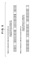
- FIG. 5 is a diagram illustrating timings according to the MAC protocol.
- FIG. 6 is a diagram illustrating an example of beacon setting details.
- FIG. 7 is a diagram illustrating an example of the internal configuration of a control station.
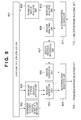
- FIG. 8 is a diagram illustrating an example of the internal configuration of a MAC protocol processing unit 702 included in a Wireless USB host 401.
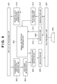
- FIG. 9 is a diagram illustrating an example of the internal configuration of a dependent station.
- FIG. 10 is a state transition diagram illustrating a state transition of the Wireless USB host 401 when a Wireless USB device 402 is on standby.
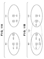
- FIGS. 11A and 11B are diagrams used to illustrate interference between wireless communication networks 400 and 410.
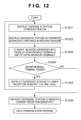
- FIG. 12 is a flowchart of a reception sensitivity control process executed by the Wireless USB host 401.
- FIG. 13 is a diagram illustrating the communication area of a Wireless USB device 402 after the reception sensitivity control process is performed.
- control station refers to a terminal that controls communication when a wireless communication network is formed in a wireless communication system.
- control station In the case of the Wireless USB standard, the control station is the Wireless USB host.
- dependent station refers to a terminal that performs communication under the control of the control station of a wireless communication system. In the case of the Wireless USB standard, the dependent station is a Wireless USB device. Control stations and dependent stations are collectively referred to as "wireless terminals".
- a configuration of a wireless frame that is defined by the MAC protocol of the UWB communication scheme will be described first.
- FIG. 1 is a diagram illustrating the overall configuration of a wireless superframe that is defined by the MAC protocol. According to the MAC protocol, access timing between wireless terminals is controlled based on a superframe having a fixed time length that is repeatedly generated.
- the time length of a superframe is about 65 milliseconds, and this superframe is divided equally into 256 timeslots. Which of these timeslots can be used as data communication timeslots is determined through transmission/reception of control signals called "beacons" between wireless terminals.
- At least one timeslot located in the beginning of a superframe is an allocated region that the wireless terminal uses to transmit the beacon, and this region is called a "beacon period”.
- FIG. 2 is a diagram illustrating a configuration of a beacon period included in a wireless superframe.
- a beacon period includes a plurality of beacon slots having a length of about 85 microseconds. The length of a beacon period depends on the number of wireless terminals, and is variable.
- the start time of a beacon period is called "BPST" (Beacon Period Start Time). This BPST can also be considered the start time of the superframe.
- a plurality of wireless terminals that form a single wireless communication network share the same BPST that corresponds to the start time of the superframe, and thus the beacons that are transmitted by each wireless terminal are configured as follows.
- FIG. 3 is a schematic diagram illustrating a configuration of a beacon that is transmitted in accordance with the MAC protocol. As shown in FIG. 3 , each wireless terminal includes, in its own beacon, its own address and its own beacon slot number that is used to transmit the beacon (301 and 302).
- Another wireless terminal that has received a beacon analyzes the content of the beacon, and can calculate the BPST that is recognized by the wireless terminal that has transmitted the beacon based on the time point at which the beacon was actually received and the beacon slot number (302) included in the beacon.
- a wireless terminal can determine the BPST that is recognized by another wireless terminal, by setting the BPST as a start reference point of the superframe, they can access in synchronization with each other.
- Each wireless terminal further includes, in its own beacon, beacon slot occupancy information 303 in which the addresses of other wireless terminals recognized by the wireless terminal are stored on a slot-number-by-slot-number basis. With this, collisions between beacon slots can be avoided.
- FIG. 3 is different from the beacon frame format that is actually defined in the ECMA-368 standard, but this does not intend to exclude information other than those shown in FIG. 3 .
- FIG. 4 is a diagram illustrating a configuration of wireless communication networks formed by wireless terminals according to Embodiment 1 of the present invention.
- the wireless terminals shown in FIG. 4 form wireless communication networks 400 and 410 with UWB Wireless USB, respectively.
- reference numeral 401 denotes a Wireless USB host (control station), and reference numerals 402 and 403 denote Wireless USB devices (dependent stations). Together they form the wireless communication network 400.
- reference numeral 411 denotes a Wireless USB host (control station), and reference numeral 412 denotes a Wireless USB device (dependent station). Together they form another wireless communication network 410, distinct from the wireless communication network 400.
- the wireless communication networks 400 and 410 are each configured as follows. First, the wireless communication networks 400 and 410 have BPSTs and beacon periods that are set at different time points as shown in FIG. 5 in their superframes. Here, such a relationship is referred to as "asynchronous", and data communication is not possible between asynchronous wireless terminals.
- the Wireless USB hosts and the Wireless USB devices are respectively assigned the second through the sixth beacon slots.
- the Wireless USB host 401 receives the beacons of the Wireless USB devices 402 and 403, so that, as shown in FIG. 6 , the addresses of the Wireless USB devices 402 and 403 are stored in slot numbers 3 and 4, respectively, as the beacon slot occupancy information. Further, the Wireless USB host 401 that sends the beacon stores its own address in slot number 2, and the fields that correspond to the other slot numbers are left blank. Basically, the same settings are made for the beacon slot occupancy information of the Wireless USB device 403.
- the Wireless USB host 411 receives the beacon of the Wireless USB device 412, so that the address of the Wireless USB device 412 is stored in slot number 6 as the beacon slot occupancy information. Further, the Wireless USB host 411 that sends the beacon stores its own address in slot number 5, and the fields that correspond to the other slot numbers are left blank. Basically, the same settings are made for the beacon slot occupancy information of the Wireless USB device 412.
- the Wireless USB device 402 receives the beacons of the Wireless USB host 401, the Wireless USB device 403, and the Wireless USB device 412. Accordingly, the addresses of these devices are stored in slot numbers 2, 4 and 6, respectively, as the beacon slot occupancy information. Further, the Wireless USB device 402 that sends the beacon stores its own address in slot number 3, and the fields that correspond to the other slot numbers are blank.
- FIG. 7 is a diagram illustrating an example of the internal configuration of a control station. The operation of each unit of a control station will be briefly explained with reference to FIG. 7 .
- the control station is the Wireless USB host 401
- the Wireless USB host 411 also has the same internal configuration.
- the Wireless USB host 401 transmits the following types of wireless frames.
- the data frame is selected by a transmission frame selection unit 705, is converted to an analog signal by a modulation unit 706, is further converted to a wireless signal by a high-frequency unit 707, and is finally transmitted to the Wireless USB device 402 through an antenna 708.
- reception frame analyzing unit 710 determines that the input wireless frame is a data frame
- the data frame is converted to a format appropriate as application data.
- the application data is transferred to the application processing unit 701 through a reception data application interface unit 709.
- a MAC protocol processing unit 702 When transmitting/receiving a beacon frame or request frame, a MAC protocol processing unit 702 is used.
- the MAC protocol processing unit 702 includes a function for transmitting and receiving beacon frames for executing a beacon protocol.
- the MAC protocol processing unit 702 further includes a function for generating a request frame for controlling the Wireless USB device 402, and a function for analyzing a response frame that is received from the Wireless USB device 402 in response to a request frame. Accordingly, if it is determined by the reception frame analyzing unit 710 that the input wireless frame is a beacon frame or request frame, the received frame is transferred to the MAC protocol processing unit 702.
- the aforementioned functions of the MAC protocol processing unit 702 will be described below.
- FIG. 8 is a diagram illustrating an example of the internal configuration of the MAC protocol processing unit 702 included in the Wireless USB host 401. There are roughly two functions that the MAC protocol processing unit 702 can achieve.
- the Wireless USB host 401 receives a beacon that is transmitted from the Wireless USB device 403, the received beacon is transmitted from a beacon/response judging unit 811 to a beacon analyzing unit 808.
- the beacon analyzing unit 808 analyzes the content of the received beacon, and transmits the result of the analysis to a beacon protocol processing unit 807.
- the beacon protocol processing unit 807 determines a parameter necessary to generate a beacon that will be transmitted from the Wireless USB host 401 according to the beacon protocol based on the content and timing of the received beacon.
- the parameter determined by the beacon protocol processing unit 807 is transmitted to a beacon generation unit 805, where a beacon that will be transmitted from the Wireless USB host 401 is generated.
- the generated beacon is transmitted to a beacon/request selection unit 806, and then finally to the Wireless USB device 403 from the antenna 708.
- a dependent station control unit 801 When establishing a communication with a dependent station on standby (the Wireless USB device 402), a dependent station control unit 801 activates.
- the dependent station control unit 801 performs processing to control the operation (beacon capture, beacon transfer, setting of reception sensitivity) of the Wireless USB device 402.
- a dependent station request setting unit 803 sets a request that needs to be transmitted to a dependent station (the Wireless USB device 402 in this case).
- a dependent station's reception sensitivity setting unit 802 determines the reception sensitivity at which the dependent station (the Wireless USB device 402 in this case) receives the request.
- a request generation unit 804 After the process described above, a request generation unit 804 generates a request frame that is used to provide an instruction, such as beacon capture, beacon transfer or setting of reception sensitivity, to the Wireless USB device 402.
- a response frame that the Wireless USB host 401 receives as a response to the request frame from the Wireless USB device 402 is analyzed by a response analyzing unit 810.
- the dependent station control unit 801 transmits instructions to the dependent station's reception sensitivity setting unit 802 and the dependent station request setting unit 803 based on the results of the analysis performed by the response analyzing unit 810.
- FIG. 9 is a diagram illustrating an example of the internal configuration of a dependent station. The operation of each unit of a dependent station will be briefly explained with reference to FIG. 9 .
- the dependent station is the Wireless USB device 402
- the Wireless USB devices 403 and 412 also have the same internal configuration.
- a data frame is transmitted/received according to the following procedure. Specifically, application data being transmitted is delivered from an application processing unit 901 to a data frame generation unit 904 through a transmission data application interface unit 903. Next, the application data is converted to a data frame having a format suitable for wireless communication by the data frame generation unit 904.
- the data frame is selected by a transmission frame selection unit 905, is converted to an analog signal by a modulation unit 906, is further converted to a wireless signal by a high-frequency unit 907, and is finally transmitted to the Wireless USB host 401 through an antenna 908.
- a data frame that is received by the antenna 908 and is converted to a baseband signal or digital signal by the high-frequency unit 907 is demodulated by a demodulation unit 912, and is transmitted to a reception frame analyzing unit 913.
- reception frame analyzing unit 913 determines that the input wireless frame is a data frame
- the data frame is converted to a format appropriate as application data.
- the application data is transferred to the application processing unit 901 through a reception data application interface unit 914.
- reception-frame analyzing unit 913 If it is determined by the reception-frame analyzing unit 913 that the input wireless frame is a beacon frame or request frame, that frame is transferred to a Wireless USB protocol processing unit 902.
- the Wireless USB protocol processing unit 902 analyzes a beacon frame, or executes processing requested by a request frame (e.g., processing that causes a detection unit 909 to set the reception sensitivity using a reception sensitivity setting signal 910).
- the Wireless USB device 402 includes the detection unit 909, so that the reception power level of a reception signal of an intermediate frequency band received from the high-frequency unit 907 can be determined.
- the obtained result is transmitted to the Wireless USB protocol processing unit 902 in the form of a frame detection signal 911.
- the detection unit 909 receives a signal of an intermediate frequency band as a reception signal from the high-frequency unit 907 for detection, but depending on the embodiment, a configuration may be employed in which the detection unit 909 detects a reception signal of a baseband frequency band or a reception signal converted to digital data.
- FIG. 10 is a state transition diagram illustrating a state transition of the Wireless USB host 401 when the Wireless USB device 402 is on standby. To put it differently, FIG. 10 shows a control process performed when the Wireless USB host 401 controls the newly activated Wireless USB device 402.
- the control of the Wireless USB device 402 is executed by transmitting a request from the Wireless USB host 401 to the Wireless USB device 402.
- the Wireless USB device 402 performs processing in accordance with this request, and notifies the Wireless USB host 401 of the results of the processing by transmitting a response corresponding to the request to the Wireless USB host 401.
- the Wireless USB host 401 controls the Wireless USB device 402 that is on standby using four different types of requests.
- Reference numeral 1001 denotes a CountPackets request.
- the CountPackets request is a request to capture a beacon.
- the Wireless USB device 402 Upon receiving the CountPackets request from the Wireless USB host 401, the Wireless USB device 402 starts capturing a beacon.
- Reference numeral 1002 denotes a CapturePacket request.
- the CapturePacket request is a request to transfer information regarding the received beacon.
- the Wireless USB device 402 Upon receiving the CapturePacket request, the Wireless USB device 402 transfers information regarding a beacon specified by this request to the Wireless USB host 401 as a response.
- the beacon information contains all of the content of the received beacon, the timing at which the beacon was received, and the quality of the reception.
- the Wireless USB host 401 can be aware of information regarding the beacon received by the Wireless USB device 402.
- Reference numeral 1003 denotes a TransmitPacket request.
- the Wireless USB device 402 Upon receiving the TransmitPacket request from the Wireless USB host 401, the Wireless USB device 402 transmits a beacon having contents specified by this request at a specified timing. By using the TransmitPacket request, the Wireless USB host 401 can cause the Wireless USB device 402 to transmit a beacon.
- Reference numeral 1004 denotes a SetWUSBData request.
- the Wireless USB device 402 receives a SetWUSBData request in which a parameter wValue is set to TransmitPower from the Wireless USB host 401. Then, the Wireless USB device 402 sets the reception sensitivity at which it receives the beacon to a value specified by this request frame.
- the Wireless USB host 401 can control the reception sensitivity of the Wireless USB device 402.
- FIGS. 11A and 11B are diagrams used to illustrate interference between the wireless communication networks 400 and 410.
- the Wireless USB device 402 is not activated. Accordingly, the Wireless USB device 402 and the Wireless USB device 412 do not communicate with each other, or their wireless frames do not collide. Further, in this state, they do not interfere with each other.
- the Wireless USB device 402 Upon being activated, the Wireless USB device 402 first detects whether or not there is a control station with which a connection should be established (the Wireless USB host 401 in this case) around the Wireless USB device 402 by capturing wireless frames.
- the Wireless USB device 402 determines the Wireless USB host 401 as the control station with which a connection should be established.
- the Wireless USB device 402 Upon making the determination, the Wireless USB device 402 connects to the Wireless USB host 401.
- the Wireless USB host 401 transmits a CountPackets request and a CapturePacket request to the Wireless USB device 402. Through this, the Wireless USB host 401 detects another Wireless USB device that is located in the surrounding environment of the Wireless USB device 402.
- the Wireless USB device 412 is included in a reception range 1101 in which the Wireless USB device 402 can receive wireless frames. Accordingly, wireless frames, such as beacons, that are transmitted by the Wireless USB device 412 interfere with the Wireless USB device 402.
- the Wireless USB device 412 transmits not only beacons, but also other wireless frames that are used for data communication, at the MAC protocol timing that is in synchronization with the wireless communication network 410. Accordingly, all of these wireless frames may interfere with the wireless communication network 400 to which the Wireless USB device 402 belongs.
- the Wireless USB host 401 controls the reception sensitivity of the activated Wireless USB device 402, whereby the influence of interference from the wireless communication network 410 is avoided.
- a reception sensitivity control process flow as performed by the Wireless USB host 401, will be described in detail.
- FIG. 12 is a flowchart of a reception sensitivity control process executed by the Wireless USB host 401 to prevent cross-interference with the wireless communication network 410 that is caused by the Wireless USB device 402.
- the Wireless USB host 401 Upon receiving a connection request from the Wireless USB device 402, the Wireless USB host 401 starts the reception sensitivity control process shown in FIG. 12 .
- step S1201 the Wireless USB host 401 issues a beacon capture request to cause the Wireless USB device 402 to capture wireless frames for a predetermined period of time to the Wireless USB device 402.
- This beacon capture request corresponds to the CountPackets request in the Wireless USB protocol, but is not particularly limited thereto as long as it is possible to cause the Wireless USB device 402 to capture beacons.
- step S1202 after a predetermined period of time specified by the beacon capture request has elapsed, the Wireless USB host 401 issues a beacon transfer request to the Wireless USB device 402.
- This beacon transfer request corresponds to the CapturePacket request in the Wireless USB protocol, but is not particularly limited thereto. Other methods can be used as long as it is possible to instruct the Wireless USB device 402 to transfer the content of the received beacon to the Wireless USB host 401.
- the Wireless USB device 402 transfers information regarding the beacon that it has received to the Wireless USB host 401 (transmission means).
- the Wireless USB host 401 receives the information (reception means).
- the beacon information includes the addresses of wireless terminals that have transmitted beacons.
- step S1203 the beacon information received from the Wireless USB device 402 is analyzed.
- the Wireless USB host 401 and the Wireless USB device 402 are included in the communication area of the Wireless USB device 402.
- the Wireless USB device 412 that belongs to the wireless communication network 410 is also included in that communication area.
- the beacon information transmitted by the Wireless USB device 402 includes the addresses of the aforementioned three wireless terminals.
- step S1203 the addresses of these three wireless terminals are classified into those of the wireless terminal that is operated in synchronization with the Wireless USB host 401 and of the wireless terminal that is operated in asynchronization with the same.
- BPST of each wireless terminal is first calculated based on the content of each beacon and the timing at which the beacon was actually received. If the BPST of a wireless terminal matches the BPST of the Wireless USB host 401, it can be determined that the wireless terminal is operated in synchronization with the Wireless USB host 401.
- the Wireless USB host 401 and the Wireless USB device 402 are classified as synchronous terminals, and the Wireless USB device 412 is classified as an asynchronous terminal. Then, the Wireless USB host 401 controls the reception sensitivity of the Wireless USB device 402 such that the wireless terminal that is operated in asynchronization does not cause interference (or reduce the influence).
- step S1204 it is determined whether or not there is a wireless terminal that is operated in asynchronization with the Wireless USB host 401 based on the classification obtained in step S1203. If it is determined in step S1204 that there is a wireless terminal that is operated in asynchronization, the process advances to step S1205, where an instruction to change the reception sensitivity (to lower by one level) is made to the Wireless USB device 402. Specifically, a reception sensitivity setting request serving as the change instruction is transmitted to the Wireless USB device 402.
- the Wireless USB device 402 Upon receiving the reception sensitivity setting request, the Wireless USB device 402 lowers its reception sensitivity by one level.
- the Wireless USB host 401 returns to step S1201 to check whether or not interference from the Wireless USB device 412 has been avoided as a result of the reception sensitivity of the Wireless USB device 402 having been lowered by one level.
- the reception sensitivity of the Wireless USB device 402 is lowered gradually by repeating the process ranging from steps S1201 to S1205 described above.
- the Wireless USB device 402 After that, if the Wireless USB device 412 moves out of the communication area of the Wireless USB device 402 ( FIG. 13 ), the Wireless USB device 402 no longer receives the beacons transmitted from the Wireless USB device 412.
- step S1206 an instruction to maintain the current reception sensitivity is made to the Wireless USB device 402.
- the Wireless USB device 402 is operated with that reception sensitivity, so that it can be operated as a wireless terminal of the wireless communication network 400 without receiving interference from the Wireless USB device 412.
- the reception sensitivity of a dependent station can be adjusted to an optimal level such that the dependent station does not receive a wireless frame from an asynchronous wireless terminal that belongs to another wireless communication network.
- interference that the wireless terminal receives from another wireless communication network can be reduced to the highest degree possible, and it is therefore possible to avoid a decrease in throughput of the entire wireless communication network that is caused by interference.
- Embodiment 1 described above has discussed a configuration in which the control of the reception sensitivity of the Wireless USB device 402 is executed by gradually lowering the reception sensitivity, but the present invention is not intended to be limited thereto, and the reception sensitivity may be controlled by gradually increasing the reception sensitivity.
- the Wireless USB host 401 causes the Wireless USB device 402 to lower its reception sensitivity to a predetermined value before proceeding to step S1201 of FIG. 12 . After that, the process ranging from steps S1201 to S1203 is performed. In step S1204, it is determined whether or not there is a wireless terminal that is operated in asynchronization with the Wireless USB host 401.
- the Wireless USB host 401 transmits an instruction to raise the reception sensitivity by one level to the Wireless USB device 402. Then, the above process is repeated until a wireless terminal that is operated in asynchronization is found. If a wireless terminal that is operated in asynchronization is found, the Wireless USB host 401 transmits an instruction to lower the reception sensitivity by one level to the Wireless USB device 402, and then transmits an instruction to maintain the current reception sensitivity to the Wireless USB device 402.
- the present invention may be applied to a system configured of a plurality of devices (e.g., a host computer, an interface device, a reader, a printer, and so on) or to an apparatus configured of a single device (e.g., a copy machine, a facsimile device, and so on).
- a system configured of a plurality of devices (e.g., a host computer, an interface device, a reader, a printer, and so on) or to an apparatus configured of a single device (e.g., a copy machine, a facsimile device, and so on).
- the object of the present invention is also achieved by supplying a recording medium, in which software program code that implements the functions of the foregoing embodiments is recorded, to a system or apparatus.
- the program code stored in the recording medium is loaded and executed by a computer (or CPU or MPU) of the system or apparatus, whereby the foregoing embodiments are achieved.
- the recording medium in which the program code is recorded falls within the scope of the present invention.
- Examples of the recording medium that can be used to supply the program code include floppy® disks, hard disks, optical disks, magneto-optical disks, CD-ROMs, CD-Rs, magnetic tape, non-volatile memory cards, and ROMs.
- the invention is not limited to the case where the functions of the above-described embodiments are implemented by executing the program code loaded by a computer.
- the present invention also includes the case where, for example, the OS (operating system) running on the computer performs part or all of the actual processing based on the instructions of the program code, and the functions of the above-described embodiments are implemented by that processing.
- the present invention further includes the case where the program code loaded from the recording medium is written into a memory included in a function expansion board inserted in the computer or a function expansion unit connected to the computer, and after that, the functions of the above-described embodiments are implemented. That is, after the program code has been written into a memory, a CPU or the like included in the function expansion board or the function expansion unit performs part or all of the actual processing based on the instructions of the program code, and the functions are implemented by that processing.
Landscapes
- Engineering & Computer Science (AREA)
- Computer Networks & Wireless Communication (AREA)
- Signal Processing (AREA)
- Mobile Radio Communication Systems (AREA)
- Small-Scale Networks (AREA)
Applications Claiming Priority (1)
| Application Number | Priority Date | Filing Date | Title |
|---|---|---|---|
| JP2007211503A JP2009049522A (ja) | 2007-08-14 | 2007-08-14 | 通信システム、通信装置および通信制御方法 |
Publications (1)
| Publication Number | Publication Date |
|---|---|
| EP2034675A2 true EP2034675A2 (en) | 2009-03-11 |
Family
ID=40042798
Family Applications (1)
| Application Number | Title | Priority Date | Filing Date |
|---|---|---|---|
| EP20080162418 Withdrawn EP2034675A2 (en) | 2007-08-14 | 2008-08-14 | Communication system, communication apparatus and communication control method |
Country Status (4)
| Country | Link |
|---|---|
| US (1) | US20090047907A1 (enExample) |
| EP (1) | EP2034675A2 (enExample) |
| JP (1) | JP2009049522A (enExample) |
| CN (1) | CN101369947A (enExample) |
Cited By (1)
| Publication number | Priority date | Publication date | Assignee | Title |
|---|---|---|---|---|
| US9042243B2 (en) | 2011-01-19 | 2015-05-26 | Qualcomm Incorporated | Adaptive peer discovery based on non peer discovery transmissions and device density for Wi-Fi |
Families Citing this family (7)
| Publication number | Priority date | Publication date | Assignee | Title |
|---|---|---|---|---|
| KR101250036B1 (ko) * | 2008-12-04 | 2013-04-03 | 한국전자통신연구원 | 센서 네트워크의 저전력 시분할 접속 방식에서 신뢰성이 높은 통신 장치 및 방법 |
| JP2010233032A (ja) * | 2009-03-27 | 2010-10-14 | Canon Inc | 制御装置、制御装置の制御方法およびプログラム |
| US20140177459A1 (en) * | 2012-12-21 | 2014-06-26 | Apple Inc. | Methods and apparatus for rapid and cost effective testing of wireless systems |
| FR3008565B1 (fr) * | 2013-07-10 | 2015-07-17 | Sagemcom Energy & Telecom Sas | Transmission de balises dans un premier reseau de communication cohabitant avec un second reseau de communication |
| JP6319312B2 (ja) * | 2013-08-23 | 2018-05-09 | 富士通株式会社 | 無線通信方法、無線通信システム、無線端末、無線基地局および制御装置 |
| CN108879958B (zh) * | 2018-07-23 | 2021-12-10 | 阳光电源股份有限公司 | 一种分布式电源系统及其通信串扰抑制方法 |
| JP7673015B2 (ja) * | 2022-03-30 | 2025-05-08 | 能美防災株式会社 | 長距離信号伝送システム |
Citations (2)
| Publication number | Priority date | Publication date | Assignee | Title |
|---|---|---|---|---|
| JP2000036981A (ja) | 1998-07-17 | 2000-02-02 | Nippon Telegr & Teleph Corp <Ntt> | 無線通信システムの電磁干渉制御方法 |
| JP2006014047A (ja) | 2004-06-28 | 2006-01-12 | Yamaha Corp | ホストコンピュータ、アクセスポイント、無線通信端末、及びネットワーク通信システム |
Family Cites Families (18)
| Publication number | Priority date | Publication date | Assignee | Title |
|---|---|---|---|---|
| US5491837A (en) * | 1994-03-07 | 1996-02-13 | Ericsson Inc. | Method and system for channel allocation using power control and mobile-assisted handover measurements |
| FI20000539L (fi) * | 2000-03-09 | 2001-09-10 | Nokia Networks Oy | Menetelmä häiriön vaikutuksen minimoimiseksi ja radiojärjestelmä |
| US7774013B2 (en) * | 2003-02-24 | 2010-08-10 | Autocell Laboratories, Inc. | Program for adjusting channel interference between access points in a wireless network |
| KR20070055637A (ko) * | 2003-06-19 | 2007-05-30 | 아이피알 라이센싱, 인코포레이티드 | 802.11 스테이션에서의 안테나 조정 |
| US7286515B2 (en) * | 2003-07-28 | 2007-10-23 | Cisco Technology, Inc. | Method, apparatus, and software product for detecting rogue access points in a wireless network |
| US7197291B2 (en) * | 2003-10-03 | 2007-03-27 | Motorola, Inc. | Multimode receiver and method for controlling signal interference |
| US7215926B2 (en) * | 2003-12-05 | 2007-05-08 | Microsoft Corporation | Enhanced mode technique for growing mesh networks |
| US7945210B2 (en) * | 2004-12-20 | 2011-05-17 | Nxp B.V. | Method and arrangement for reducing the mutual interference of network subscribers in radio networks |
| JP4509822B2 (ja) * | 2005-02-24 | 2010-07-21 | Okiセミコンダクタ株式会社 | 無線集積回路 |
| US20060256747A1 (en) * | 2005-05-16 | 2006-11-16 | Mikko Jaakkola | Terminal assisted WLAN access point rate adaptation |
| US7801546B2 (en) * | 2005-09-26 | 2010-09-21 | Cisco Technology, Inc. | Distributing configuration parameters in a high density network |
| US7701913B2 (en) * | 2005-10-31 | 2010-04-20 | Intel Corporation | Methods and apparatus for providing a platform coexistence system of multiple wireless communication devices |
| US8219129B2 (en) * | 2006-01-06 | 2012-07-10 | Proxense, Llc | Dynamic real-time tiered client access |
| US8502729B2 (en) * | 2006-01-30 | 2013-08-06 | Lawrence Livermore National Security, Llc | Ultra-wideband radar sensors and networks |
| US20070223626A1 (en) * | 2006-03-21 | 2007-09-27 | Shay Waxman | Dynamic analog power management in mobile station receivers |
| US20080274728A1 (en) * | 2007-05-01 | 2008-11-06 | Ian Bancroft Anderson | Inferring a state of activity of a carrier of a mobile device |
| JP2008306549A (ja) * | 2007-06-08 | 2008-12-18 | Canon Inc | 無線制御局、及び無線端末局の制御方法、当該制御方法をコンピュータに実行させるためのコンピュータプログラム |
| JP4921281B2 (ja) * | 2007-08-14 | 2012-04-25 | キヤノン株式会社 | 通信装置および通信制御方法 |
-
2007
- 2007-08-14 JP JP2007211503A patent/JP2009049522A/ja active Pending
-
2008
- 2008-07-31 US US12/183,860 patent/US20090047907A1/en not_active Abandoned
- 2008-08-14 EP EP20080162418 patent/EP2034675A2/en not_active Withdrawn
- 2008-08-14 CN CNA2008101457521A patent/CN101369947A/zh active Pending
Patent Citations (2)
| Publication number | Priority date | Publication date | Assignee | Title |
|---|---|---|---|---|
| JP2000036981A (ja) | 1998-07-17 | 2000-02-02 | Nippon Telegr & Teleph Corp <Ntt> | 無線通信システムの電磁干渉制御方法 |
| JP2006014047A (ja) | 2004-06-28 | 2006-01-12 | Yamaha Corp | ホストコンピュータ、アクセスポイント、無線通信端末、及びネットワーク通信システム |
Cited By (1)
| Publication number | Priority date | Publication date | Assignee | Title |
|---|---|---|---|---|
| US9042243B2 (en) | 2011-01-19 | 2015-05-26 | Qualcomm Incorporated | Adaptive peer discovery based on non peer discovery transmissions and device density for Wi-Fi |
Also Published As
| Publication number | Publication date |
|---|---|
| JP2009049522A (ja) | 2009-03-05 |
| US20090047907A1 (en) | 2009-02-19 |
| CN101369947A (zh) | 2009-02-18 |
Similar Documents
| Publication | Publication Date | Title |
|---|---|---|
| EP2034675A2 (en) | Communication system, communication apparatus and communication control method | |
| US8046021B2 (en) | Communication system, communication apparatus, and communication method to minimize interference by transmission power control | |
| KR101287648B1 (ko) | 전력 제어 방법 및 송신 전력 변경 시스템 | |
| US8874034B2 (en) | Method and system for quick Bluetooth low energy (BLE) protocol signal presence detection for coexistence | |
| US8081998B2 (en) | Communication apparatus and communication control method with power adjustment to avoid interference between apparatuses on first and second networks | |
| US8310996B2 (en) | Conditional scheduling for asynchronous wireless communication | |
| US9661649B2 (en) | Determining a transmit parameter for wireless communication | |
| US20120201156A1 (en) | Wireless communication device | |
| US8737313B2 (en) | Transmit time segments for asynchronous wireless communication | |
| EP2106075B1 (en) | Control device and communication control method | |
| US8072964B2 (en) | Communication apparatus for connecting to another apparatus in accordance with occupancy of beacon slots and communication method for the same | |
| EP1232576A2 (en) | Power control in a radio communication system | |
| JP2005295107A (ja) | 無線通信装置および無線通信システム並びに通信タイミング調停装置 | |
| US20250374189A1 (en) | Method and device for low power operation in wireless lan supporting mlsr operation | |
| WO2020137365A1 (ja) | 通信装置、通信装置の制御方法、およびプログラム | |
| US20250275004A1 (en) | Wireless communication device, control method, and non-transitory computer-readable storage medium | |
| CN105451316B (zh) | 一种无线通信方法和设备 | |
| KR102880105B1 (ko) | Wlan 통신 시스템에서 obss pd 레벨을 결정하기 위한 방법 및 장치 | |
| KR20020030830A (ko) | 무선 통신 시스템 |
Legal Events
| Date | Code | Title | Description |
|---|---|---|---|
| PUAI | Public reference made under article 153(3) epc to a published international application that has entered the european phase |
Free format text: ORIGINAL CODE: 0009012 |
|
| AK | Designated contracting states |
Kind code of ref document: A2 Designated state(s): AT BE BG CH CY CZ DE DK EE ES FI FR GB GR HR HU IE IS IT LI LT LU LV MC MT NL NO PL PT RO SE SI SK TR |
|
| AX | Request for extension of the european patent |
Extension state: AL BA MK RS |
|
| STAA | Information on the status of an ep patent application or granted ep patent |
Free format text: STATUS: THE APPLICATION HAS BEEN WITHDRAWN |
|
| 18W | Application withdrawn |
Effective date: 20120726 |