EP2034237B1 - Energy-saving lampshade with even light distribution - Google Patents
Energy-saving lampshade with even light distribution Download PDFInfo
- Publication number
- EP2034237B1 EP2034237B1 EP08105216A EP08105216A EP2034237B1 EP 2034237 B1 EP2034237 B1 EP 2034237B1 EP 08105216 A EP08105216 A EP 08105216A EP 08105216 A EP08105216 A EP 08105216A EP 2034237 B1 EP2034237 B1 EP 2034237B1
- Authority
- EP
- European Patent Office
- Prior art keywords
- light
- reflector
- lampshade
- transmissive plate
- condenser
- Prior art date
- Legal status (The legal status is an assumption and is not a legal conclusion. Google has not performed a legal analysis and makes no representation as to the accuracy of the status listed.)
- Not-in-force
Links
- 238000005286 illumination Methods 0.000 claims abstract description 17
- 230000003287 optical effect Effects 0.000 claims description 26
- NIXOWILDQLNWCW-UHFFFAOYSA-N acrylic acid group Chemical group C(C=C)(=O)O NIXOWILDQLNWCW-UHFFFAOYSA-N 0.000 description 13
- 230000000694 effects Effects 0.000 description 4
- 238000012986 modification Methods 0.000 description 1
- 230000004048 modification Effects 0.000 description 1
- 230000005855 radiation Effects 0.000 description 1
Images


Classifications
-
- F—MECHANICAL ENGINEERING; LIGHTING; HEATING; WEAPONS; BLASTING
- F21—LIGHTING
- F21V—FUNCTIONAL FEATURES OR DETAILS OF LIGHTING DEVICES OR SYSTEMS THEREOF; STRUCTURAL COMBINATIONS OF LIGHTING DEVICES WITH OTHER ARTICLES, NOT OTHERWISE PROVIDED FOR
- F21V7/00—Reflectors for light sources
- F21V7/04—Optical design
- F21V7/09—Optical design with a combination of different curvatures
-
- F—MECHANICAL ENGINEERING; LIGHTING; HEATING; WEAPONS; BLASTING
- F21—LIGHTING
- F21V—FUNCTIONAL FEATURES OR DETAILS OF LIGHTING DEVICES OR SYSTEMS THEREOF; STRUCTURAL COMBINATIONS OF LIGHTING DEVICES WITH OTHER ARTICLES, NOT OTHERWISE PROVIDED FOR
- F21V1/00—Shades for light sources, i.e. lampshades for table, floor, wall or ceiling lamps
- F21V1/14—Covers for frames; Frameless shades
- F21V1/146—Frameless shades
-
- F—MECHANICAL ENGINEERING; LIGHTING; HEATING; WEAPONS; BLASTING
- F21—LIGHTING
- F21V—FUNCTIONAL FEATURES OR DETAILS OF LIGHTING DEVICES OR SYSTEMS THEREOF; STRUCTURAL COMBINATIONS OF LIGHTING DEVICES WITH OTHER ARTICLES, NOT OTHERWISE PROVIDED FOR
- F21V13/00—Producing particular characteristics or distribution of the light emitted by means of a combination of elements specified in two or more of main groups F21V1/00 - F21V11/00
- F21V13/02—Combinations of only two kinds of elements
- F21V13/04—Combinations of only two kinds of elements the elements being reflectors and refractors
-
- F—MECHANICAL ENGINEERING; LIGHTING; HEATING; WEAPONS; BLASTING
- F21—LIGHTING
- F21V—FUNCTIONAL FEATURES OR DETAILS OF LIGHTING DEVICES OR SYSTEMS THEREOF; STRUCTURAL COMBINATIONS OF LIGHTING DEVICES WITH OTHER ARTICLES, NOT OTHERWISE PROVIDED FOR
- F21V13/00—Producing particular characteristics or distribution of the light emitted by means of a combination of elements specified in two or more of main groups F21V1/00 - F21V11/00
- F21V13/12—Combinations of only three kinds of elements
-
- F—MECHANICAL ENGINEERING; LIGHTING; HEATING; WEAPONS; BLASTING
- F21—LIGHTING
- F21V—FUNCTIONAL FEATURES OR DETAILS OF LIGHTING DEVICES OR SYSTEMS THEREOF; STRUCTURAL COMBINATIONS OF LIGHTING DEVICES WITH OTHER ARTICLES, NOT OTHERWISE PROVIDED FOR
- F21V3/00—Globes; Bowls; Cover glasses
- F21V3/04—Globes; Bowls; Cover glasses characterised by materials, surface treatments or coatings
- F21V3/049—Patterns or structured surfaces for diffusing light, e.g. frosted surfaces
-
- F—MECHANICAL ENGINEERING; LIGHTING; HEATING; WEAPONS; BLASTING
- F21—LIGHTING
- F21V—FUNCTIONAL FEATURES OR DETAILS OF LIGHTING DEVICES OR SYSTEMS THEREOF; STRUCTURAL COMBINATIONS OF LIGHTING DEVICES WITH OTHER ARTICLES, NOT OTHERWISE PROVIDED FOR
- F21V5/00—Refractors for light sources
- F21V5/002—Refractors for light sources using microoptical elements for redirecting or diffusing light
Definitions
- the present invention relates to a lampshade for lamp and more particularly, to an energy-saving lampshade with expected light distribution, which is environmentally friendly and practical for home, factory and street applications and, which is designed subject to the principles of optical reflection, refraction and critical angles, lowering light loss, assuring even distribution of light in the illumination area and, avoiding dazzling.
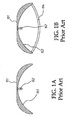
- FIG. 1 illustrates a conventional indoor lighting fixture, which comprises a light source 102 , and an open type opaque lampshade 101 provided at the top side of the light source 102 .
- the open type opaque lampshade 101 has a reflective inner surface 103 .
- the surface of the light source is usually frosted.
- Regular outdoor lighting fixtures are usually equipped with a full-closed lampshade (see FIG. 1B ) in which the bottom light transmissive cover 104 is frosted to avoid dazzle.
- conventional lighting fixtures either with an open type lampshade or a full-closed type lampshade, have the common drawbacks of big brightness loss and local concentration of light right below the light source.
- WO 2007/138321 is the document on which the pre characterizing part of claim 1 is based on. It concerns lighting systems and particularly active lighting systems which are capable of providing automated changing lighting effects.
- the lighting system comprises a light source, a deflector positioned within the path of light emitted by the light source, and a reflector wherein at least one of the reflector and deflector is moveable relative to the other of the reflector and the deflector.
- EP 0 683 355 A1 discloses a vehicle light for motor vehicles, which comprises at least one light emitting device and one reflector.
- a prism is arranged in the optical path, which reflects the light beams emitted from the light emitting device to the at least one reflector.
- the reflector reflects the light beams onto a light transmissive cover on the front side of the vehicle light.
- a lighting device which comprises a light source, a convex reflector for receiving light from the light source and a concave reflector for receiving light from the convex reflector.
- the convex reflector reflects the light beams onto a transparent or translucent disc like cover on the front side of the lighting device.
- WO 1998/37359 discloses a lighting fitting for an essentially point shaped light source, including a reflector and a light spreading cover.
- the cover further includes a first outer conical surface of prism film with standing prisms turned inwardly, said surface converging in a direction from the reflector, and a second, inner, conical surface of prism film with standing prisms turned inwardly inside, attaching to the first conical surface and converging in the direction of the reflector, whereby the reflector is shaped as a shallow bowl and placed such with respect to the light source that essentially all light from the light source being directly reflected meets the outer cone surface.
- the present invention has been accomplished under the circumstances in view. It is one object of the present invention to provide an energy-saving lampshade, which eliminates the problem of uneven distribution of light in which the light intensity at the center area within the illumination space right below the light source is greater than the border area.
- the invention provides a light condenser configured to show a parabolic curve or elliptic curve and mounted inside the lampshade for condensing the light from the light source onto a reflector cone right below the light source, and a curved light reflector with facets at different angles for reflecting reflected light from the reflector cone toward predetermined illumination block areas. Through multiple reflections, light is evenly distributed.
- the invention provides a light-transmissive plate for output of light.
- the light-transmissive plate comprises an optical grating on its one side for controlling passing of light through the light-transmissive plate in such a manner that the incident angles of the light rays that fall at the light-transmissive plate at certain angles are greater than the critical angles of the light-transmissive plate, achieving full reflection and avoiding dazzling without reducing the brightness.
- the invention achieves a power saving effect.
- a lampshade body 701 is shown having a top through hole 702 in which a lamp holder 703 is installed to hold a light emitting device 704 that emits light when electrically connected.
- the lampshade body 701 has mounted therein a light condenser 708 and a curved light reflector 705 .
- the light condenser 708 that is disposed above the imaginary line 709 can be configured to show a parabolic curve or partially elliptic curve.
- the light condenser 708 is configured to show a parabolic curve.
- the light condenser 708 has a through hole for the passing of the light emitting device 704.
- the curved light reflector 705 that is disposed below the imaginary line 709 is a fixedly mounted inside the lampshade body 701 and connected to the light condenser 708.
- a light-transmissive plate 706 is detachably covered on the bottom side of the lampshade body 701 within the illumination area.
- a reflector cone 707 is fixedly mounted on the inner side of the light-transmissive plate 706 within the lampshade body 701 in such a position that the vertex of the reflector cone 707 is aimed at the light emitting device 704 and, the light condenser 708 condenses the emitted light from the light emitting device 704 onto the reflector cone 707 for enabling the reflector cone 707 to reflect the condensed light onto the curved light reflector 705 that reflects the deflected light from the reflector cone 707 toward the illumination area to achieve the desired light distribution.
- the curved light reflector 705 is formed of multiple facets, and the size of each facet of the curved light reflector 705 and the angle of each facet of the curved light reflector 705 relative to the horizontal line are calculated subject to the principle of optical reflection and expected contained angle between the incident light and the light reflected by each facet toward a specific illumination block.
- FIG. 3 is an enlarged view of part 203 of the curved light reflector 705.
- the incident light 107 in a predetermined direction falls on one facet 105 and is being reflected by the facet 105 onto a specific illumination block 114
- the incident light 107 and the reflected light 108 define a contained angle ( f ) 117.
- the accurate angle of the normal line 113 is obtained. Because the normal line 113 is perpendicular to the facet 105 , the angle ( e ) 112 relative to the horizontal line 111 can thus be obtained.
- the light-transmissive plate 706 comprises a plurality of critical angles, and at least one side of the light-transmissive plate 706 is provided with an optical grating.
- the open space, angle, specification and shape of the optical grating is determined subject to the optical critical angles of the material of the light-transmissive plate 706, such that the incident angle of the light rays emitted by the light emitting device 704 are greater than the critical angles, and the light rays emitted by the light emitting device 704 are fully reflected without passing through the light-transmissive plate 706 directly; the incident angles of the light rays that are not directly emitted by the light emitting device 704 are smaller than the critical angles. And the light rays that are not directly emitted by the light emitting device 704 directly go through the light-transmissive plate 706.
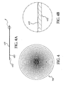
- the light-transmissive plate 706 shown in FIG. 2 can be a circular optical grating plate 401 .
- the circular optical grating plate 401 has a grating of multiple annular lines 403 concentrically formed on its one side.
- the other side of the circular optical grating plate 401 can be a planar surface or provided with a grating of concentrically arranged annular lines.
- the other side of the circular optical grating plate 401 is a planar surface 402 .
- the light-transmissive plate 706 shown in FIG. 2 can be a rectangular optical grating plate 501.
- the rectangular optical grating plate 501 has a grating of multiple straight lines 503 formed on its one side.
- the other side of the rectangular optical grating plate 501 can be a planar surface or provided with a grating of linear lines.
- the other side of the rectangular optical grating plate 501 is a planar surface 502 .
- FIGS. 4 and 5 show two different shapes of optical grating plates that have different grating spaces, grating angles and grating shapes for controlling every light ray that falls at the optical grating to pass through or to be reflected.
- it is designed to have the incident angle of the light ray to be smaller than the corresponding critical angle of the light-transmissive plate.
- it is designed to have the incident angle of the light ray to be greater than the corresponding critical angle of the light-transmissive plate.
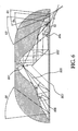
- the critical angle of the acrylic light-transmissive plate, referenced by 803 is 42.15°.
- the critical angle of the acrylic light-transmissive plate 803 is 42.15°.
- one light ray 802 from the light source 801 fell at the surface of the acrylic light-transmissive plate 803 after through two reflections, it is refracted onto the optical grating at the other side of the acrylic light-transmissive plate 803 at 41.75° incident angle ( ⁇ 1 ) 804. Because this 41.75° incident angle ( ⁇ 1 ) 804 is smaller than the critical angle 42.15° of the acrylic light-transmissive plate 803 , this light ray is refracted through the acrylic light-transmissive plate 803 again and then enters the illumination space.
- the incident angles ⁇ 2 ⁇ 5 of the other light rays are 37.72°, 38.91°, 28.34° and 22.64° respectively that are smaller than the critical angle 42.15° of the acrylic light-transmissive plate 803 , and therefore these light rays are refracted through the acrylic light-transmissive plate 803 again and then enter the illumination space.
- Another light ray 805 from the light source 801 that fell at the surface of the acrylic light-transmissive plate 803 is refracted onto the optical grating at the other side of the acrylic light-transmissive plate 803 at 42.83 incident angle ( ⁇ 6 ) 806. Because this 42.83 incident angle ( ⁇ 6 ) 806 is greater than the critical angle 42.15° of the acrylic light-transmissive plate 803 , this light ray is fully reflected without passing through the acrylic light-transmissive plate 803 .
- the incident angles ⁇ 7 and ⁇ 8 of the other light rays are 43.46° and 42.72° respectively that are greater than the critical angle 42.15° of the acrylic light-transmissive plate 803, and therefore these light rays are fully reflected without passing through the acrylic light-transmissive plate 803.
- the light condenser 708 that is mounted inside the lampshade and configured to show a parabolic curve or partially elliptic curve condenses light rays onto the surface of the reflector cone 707;
- the curved light reflector 705 is formed of multiple facets of different sizes and angles effectively reflects light rays toward the predetermined illumination space, achieving an even distribution of light;
- the reflector cone 707 is arranged right below the light source to have a part of the light rays to be projected onto the expected illumination blocks through multiple reflections, assuring accurate radiation of light rays onto specific blocks.
- the light-transmissive plate 706 is a covering at the illumination side, having optical gratings arranged on one surface thereof at different angles for controlling passing of the light rays of which the incident angles are greater than the critical angle of the light-transmissive plate 706 so that all the light rays that pass through the light-transmissive plate 706 had been reflected at least once, avoiding dazzling and brightness loss, and achieving a power saving effect.
- FIG. 7 is a schematic sectional view of another energy-saving lampshade. It comprises a lampshade body 601, which has a top through hole 602 in which a lamp holder 603 is installed to hold a light emitting device 604 that emits light when electrically connected, a light condenser 608 , which is configured to show a parabolic curve or partially elliptic curve and has a through hole for the passing of the light emitting device 604 , a curved light reflector 605 fixedly mounted inside the lampshade body 601 and connected to the light condenser 608 , a light-transmissive plate 606 detachably covered on the bottom side of the lampshade body 601 , and a reflector cone 607 fixedly mounted on the inner side of the light-transmissive plate 606 with the vertex thereof aimed at the light emitting device 604.
- a lampshade body 601 which has a top through hole 602 in which a lamp holder 603 is installed to hold a light emit
- the curved light reflector 605 and the light condenser 608 are designed in the same way as previously described.
- the lampshade also achieves the effect of providing even illumination, avoiding brightness loss for energy saving.
Applications Claiming Priority (1)
| Application Number | Priority Date | Filing Date | Title |
|---|---|---|---|
| TW096132995A TW200912195A (en) | 2007-09-05 | 2007-09-05 | Light-spreading and energy-saving shade |
Publications (2)
| Publication Number | Publication Date |
|---|---|
| EP2034237A1 EP2034237A1 (en) | 2009-03-11 |
| EP2034237B1 true EP2034237B1 (en) | 2010-11-17 |
Family
ID=39865576
Family Applications (1)
| Application Number | Title | Priority Date | Filing Date |
|---|---|---|---|
| EP08105216A Not-in-force EP2034237B1 (en) | 2007-09-05 | 2008-09-03 | Energy-saving lampshade with even light distribution |
Country Status (8)
| Country | Link |
|---|---|
| US (1) | US20090059597A1 (zh) |
| EP (1) | EP2034237B1 (zh) |
| JP (1) | JP5042173B2 (zh) |
| KR (1) | KR20090025174A (zh) |
| AT (1) | ATE488731T1 (zh) |
| DE (1) | DE602008003497D1 (zh) |
| ES (1) | ES2356699T3 (zh) |
| TW (1) | TW200912195A (zh) |
Families Citing this family (6)
| Publication number | Priority date | Publication date | Assignee | Title |
|---|---|---|---|---|
| US20120020091A1 (en) * | 2010-07-22 | 2012-01-26 | Chia-Mao Li | High power wide coverage light reflection lamp seat |
| US8534881B2 (en) | 2012-01-23 | 2013-09-17 | Southpac Trust International Inc. | Light reflector cone |
| TWI487868B (zh) * | 2012-07-25 | 2015-06-11 | 隆達電子股份有限公司 | 多指向性發光裝置及其運作方法 |
| KR20140094314A (ko) * | 2013-01-22 | 2014-07-30 | 서울반도체 주식회사 | Led 램프 |
| TWI580894B (zh) * | 2013-09-18 | 2017-05-01 | 鴻海精密工業股份有限公司 | 透鏡 |
| CN113606558B (zh) * | 2021-07-12 | 2023-07-14 | 宁波公牛光电科技有限公司 | 光学结构和灯结构 |
Family Cites Families (13)
| Publication number | Priority date | Publication date | Assignee | Title |
|---|---|---|---|---|
| US4037096A (en) * | 1974-08-09 | 1977-07-19 | American Sterilizer Company | Illuminator apparatus using optical reflective methods |
| US4617619A (en) * | 1985-10-02 | 1986-10-14 | American Sterilizer Company | Reflector for multiple source lighting fixture |
| US4937715A (en) * | 1989-01-26 | 1990-06-26 | Kirschner Medical Corporation | Lamp system for operating theatres and the like |
| US5128848A (en) * | 1989-03-31 | 1992-07-07 | W.C. Heraeus Gmbh | Operating light |
| JPH07235202A (ja) * | 1994-02-21 | 1995-09-05 | Nissan Motor Co Ltd | 車両用灯具の光源装置 |
| DE4417695C2 (de) * | 1994-05-20 | 1998-01-29 | Reitter & Schefenacker Gmbh | Kraftfahrzeugleuchte |
| SE509053C2 (sv) * | 1997-02-21 | 1998-11-30 | Gerhard Rehm | Belysningsarmatur för en väsentligen punktformig ljuskälla |
| EP1148860A4 (en) * | 1998-12-17 | 2002-10-09 | Getinge Castle Inc | LIGHTING SYSTEM FOR SURGICAL FACILITIES |
| JP4165786B2 (ja) * | 1999-08-09 | 2008-10-15 | スタンレー電気株式会社 | 車両用信号灯具 |
| JP2001216805A (ja) * | 2000-02-02 | 2001-08-10 | Stanley Electric Co Ltd | 灯 具 |
| JP2004288428A (ja) * | 2003-03-20 | 2004-10-14 | Braun Kk | 光線フィルター |
| US20060077667A1 (en) * | 2004-10-07 | 2006-04-13 | Choon Nang Electrical Appliance Mfy., Ltd. | Lighting device |
| GB2438637A (en) * | 2006-05-31 | 2007-12-05 | Jacob Dyson | Active lighting system having automatically changing light effect. |
-
2007
- 2007-09-05 TW TW096132995A patent/TW200912195A/zh not_active IP Right Cessation
-
2008
- 2008-09-02 US US12/230,569 patent/US20090059597A1/en not_active Abandoned
- 2008-09-03 AT AT08105216T patent/ATE488731T1/de not_active IP Right Cessation
- 2008-09-03 DE DE602008003497T patent/DE602008003497D1/de active Active
- 2008-09-03 EP EP08105216A patent/EP2034237B1/en not_active Not-in-force
- 2008-09-03 ES ES08105216T patent/ES2356699T3/es active Active
- 2008-09-05 KR KR1020080087668A patent/KR20090025174A/ko not_active Application Discontinuation
- 2008-09-05 JP JP2008227897A patent/JP5042173B2/ja not_active Expired - Fee Related
Also Published As
| Publication number | Publication date |
|---|---|
| DE602008003497D1 (de) | 2010-12-30 |
| EP2034237A1 (en) | 2009-03-11 |
| ES2356699T3 (es) | 2011-04-12 |
| TW200912195A (en) | 2009-03-16 |
| US20090059597A1 (en) | 2009-03-05 |
| ATE488731T1 (de) | 2010-12-15 |
| JP5042173B2 (ja) | 2012-10-03 |
| JP2009081131A (ja) | 2009-04-16 |
| TWI322868B (zh) | 2010-04-01 |
| KR20090025174A (ko) | 2009-03-10 |
Similar Documents
| Publication | Publication Date | Title |
|---|---|---|
| EP2378337B1 (en) | Light shaping lens for LED with a light output surface having portions with differing shapes | |
| US8469552B2 (en) | Street lighting device | |
| US20040105262A1 (en) | LED light source with reflecting side wall | |
| EP2034237B1 (en) | Energy-saving lampshade with even light distribution | |
| EP3754248B1 (en) | Optical element and lighting lamp with the same | |
| JP6868016B2 (ja) | 照明システム及び光出力を生成する方法 | |
| KR100765995B1 (ko) | 발광다이오드 광원 헤드 램프 | |
| US10948150B2 (en) | Multi-beam vehicle light | |
| EP2780627B1 (en) | Led illuminating device | |
| US20090122546A1 (en) | Movable Lighting System Providing Adjustable Illumination Zone | |
| CN103511935A (zh) | 照明装置 | |
| US20120039076A1 (en) | Energy-saving lighting device with even distribution of light | |
| CN112254026A (zh) | 一种防眩灯具以及采用该灯具的照明布置方法 | |
| CN100567797C (zh) | 照明系统 | |
| US10801698B2 (en) | High visual comfort road and urban LED lighting | |
| KR101464277B1 (ko) | 틸트 구조의 등기구용 복합 굴절 렌즈 및 이를 갖는 가로등 장치 | |
| KR101089786B1 (ko) | 단방향 투사가 가능한 비대칭형 led 렌즈 및 이를 사용하는 led 램프 | |
| TWI795896B (zh) | 發光裝置 | |
| CN219473486U (zh) | 智能灯具 | |
| CN219346302U (zh) | 光学组件及灯具 | |
| CN107062026B (zh) | 一种复合全反射led射灯透镜 | |
| JP7227562B2 (ja) | 照明装置 | |
| CN102606901A (zh) | 一种led平面光源 | |
| CN114278907A (zh) | 一种透镜及偏配光灯具 | |
| CN111911888A (zh) | 一种鱼鳞混光透镜 |
Legal Events
| Date | Code | Title | Description |
|---|---|---|---|
| PUAI | Public reference made under article 153(3) epc to a published international application that has entered the european phase |
Free format text: ORIGINAL CODE: 0009012 |
|
| AK | Designated contracting states |
Kind code of ref document: A1 Designated state(s): AT BE BG CH CY CZ DE DK EE ES FI FR GB GR HR HU IE IS IT LI LT LU LV MC MT NL NO PL PT RO SE SI SK TR |
|
| AX | Request for extension of the european patent |
Extension state: AL BA MK RS |
|
| RIN1 | Information on inventor provided before grant (corrected) |
Inventor name: CHUANG, PING-HAN |
|
| RAP1 | Party data changed (applicant data changed or rights of an application transferred) |
Owner name: XEDON TECHNOLOGY CO., LTD. |
|
| 17P | Request for examination filed |
Effective date: 20090824 |
|
| 17Q | First examination report despatched |
Effective date: 20091013 |
|
| AKX | Designation fees paid |
Designated state(s): AT BE BG CH CY CZ DE DK EE ES FI FR GB GR HR HU IE IS IT LI LT LU LV MC MT NL NO PL PT RO SE SI SK TR |
|
| GRAP | Despatch of communication of intention to grant a patent |
Free format text: ORIGINAL CODE: EPIDOSNIGR1 |
|
| GRAS | Grant fee paid |
Free format text: ORIGINAL CODE: EPIDOSNIGR3 |
|
| GRAA | (expected) grant |
Free format text: ORIGINAL CODE: 0009210 |
|
| AK | Designated contracting states |
Kind code of ref document: B1 Designated state(s): AT BE BG CH CY CZ DE DK EE ES FI FR GB GR HR HU IE IS IT LI LT LU LV MC MT NL NO PL PT RO SE SI SK TR |
|
| REG | Reference to a national code |
Ref country code: GB Ref legal event code: FG4D |
|
| REG | Reference to a national code |
Ref country code: CH Ref legal event code: EP |
|
| REG | Reference to a national code |
Ref country code: IE Ref legal event code: FG4D |
|
| REF | Corresponds to: |
Ref document number: 602008003497 Country of ref document: DE Date of ref document: 20101230 Kind code of ref document: P |
|
| REG | Reference to a national code |
Ref country code: NL Ref legal event code: T3 |
|
| REG | Reference to a national code |
Ref country code: ES Ref legal event code: FG2A Ref document number: 2356699 Country of ref document: ES Kind code of ref document: T3 Effective date: 20110412 |
|
| LTIE | Lt: invalidation of european patent or patent extension |
Effective date: 20101117 |
|
| PG25 | Lapsed in a contracting state [announced via postgrant information from national office to epo] |
Ref country code: NO Free format text: LAPSE BECAUSE OF FAILURE TO SUBMIT A TRANSLATION OF THE DESCRIPTION OR TO PAY THE FEE WITHIN THE PRESCRIBED TIME-LIMIT Effective date: 20110217 Ref country code: LT Free format text: LAPSE BECAUSE OF FAILURE TO SUBMIT A TRANSLATION OF THE DESCRIPTION OR TO PAY THE FEE WITHIN THE PRESCRIBED TIME-LIMIT Effective date: 20101117 |
|
| PG25 | Lapsed in a contracting state [announced via postgrant information from national office to epo] |
Ref country code: HR Free format text: LAPSE BECAUSE OF FAILURE TO SUBMIT A TRANSLATION OF THE DESCRIPTION OR TO PAY THE FEE WITHIN THE PRESCRIBED TIME-LIMIT Effective date: 20101117 Ref country code: LV Free format text: LAPSE BECAUSE OF FAILURE TO SUBMIT A TRANSLATION OF THE DESCRIPTION OR TO PAY THE FEE WITHIN THE PRESCRIBED TIME-LIMIT Effective date: 20101117 Ref country code: IS Free format text: LAPSE BECAUSE OF FAILURE TO SUBMIT A TRANSLATION OF THE DESCRIPTION OR TO PAY THE FEE WITHIN THE PRESCRIBED TIME-LIMIT Effective date: 20110317 Ref country code: SI Free format text: LAPSE BECAUSE OF FAILURE TO SUBMIT A TRANSLATION OF THE DESCRIPTION OR TO PAY THE FEE WITHIN THE PRESCRIBED TIME-LIMIT Effective date: 20101117 Ref country code: AT Free format text: LAPSE BECAUSE OF FAILURE TO SUBMIT A TRANSLATION OF THE DESCRIPTION OR TO PAY THE FEE WITHIN THE PRESCRIBED TIME-LIMIT Effective date: 20101117 Ref country code: FI Free format text: LAPSE BECAUSE OF FAILURE TO SUBMIT A TRANSLATION OF THE DESCRIPTION OR TO PAY THE FEE WITHIN THE PRESCRIBED TIME-LIMIT Effective date: 20101117 Ref country code: CY Free format text: LAPSE BECAUSE OF FAILURE TO SUBMIT A TRANSLATION OF THE DESCRIPTION OR TO PAY THE FEE WITHIN THE PRESCRIBED TIME-LIMIT Effective date: 20101117 Ref country code: PT Free format text: LAPSE BECAUSE OF FAILURE TO SUBMIT A TRANSLATION OF THE DESCRIPTION OR TO PAY THE FEE WITHIN THE PRESCRIBED TIME-LIMIT Effective date: 20110317 Ref country code: BG Free format text: LAPSE BECAUSE OF FAILURE TO SUBMIT A TRANSLATION OF THE DESCRIPTION OR TO PAY THE FEE WITHIN THE PRESCRIBED TIME-LIMIT Effective date: 20110217 Ref country code: SE Free format text: LAPSE BECAUSE OF FAILURE TO SUBMIT A TRANSLATION OF THE DESCRIPTION OR TO PAY THE FEE WITHIN THE PRESCRIBED TIME-LIMIT Effective date: 20101117 |
|
| PG25 | Lapsed in a contracting state [announced via postgrant information from national office to epo] |
Ref country code: GR Free format text: LAPSE BECAUSE OF FAILURE TO SUBMIT A TRANSLATION OF THE DESCRIPTION OR TO PAY THE FEE WITHIN THE PRESCRIBED TIME-LIMIT Effective date: 20110218 |
|
| PG25 | Lapsed in a contracting state [announced via postgrant information from national office to epo] |
Ref country code: CZ Free format text: LAPSE BECAUSE OF FAILURE TO SUBMIT A TRANSLATION OF THE DESCRIPTION OR TO PAY THE FEE WITHIN THE PRESCRIBED TIME-LIMIT Effective date: 20101117 Ref country code: BE Free format text: LAPSE BECAUSE OF FAILURE TO SUBMIT A TRANSLATION OF THE DESCRIPTION OR TO PAY THE FEE WITHIN THE PRESCRIBED TIME-LIMIT Effective date: 20101117 Ref country code: EE Free format text: LAPSE BECAUSE OF FAILURE TO SUBMIT A TRANSLATION OF THE DESCRIPTION OR TO PAY THE FEE WITHIN THE PRESCRIBED TIME-LIMIT Effective date: 20101117 |
|
| PG25 | Lapsed in a contracting state [announced via postgrant information from national office to epo] |
Ref country code: RO Free format text: LAPSE BECAUSE OF FAILURE TO SUBMIT A TRANSLATION OF THE DESCRIPTION OR TO PAY THE FEE WITHIN THE PRESCRIBED TIME-LIMIT Effective date: 20101117 Ref country code: PL Free format text: LAPSE BECAUSE OF FAILURE TO SUBMIT A TRANSLATION OF THE DESCRIPTION OR TO PAY THE FEE WITHIN THE PRESCRIBED TIME-LIMIT Effective date: 20101117 Ref country code: DK Free format text: LAPSE BECAUSE OF FAILURE TO SUBMIT A TRANSLATION OF THE DESCRIPTION OR TO PAY THE FEE WITHIN THE PRESCRIBED TIME-LIMIT Effective date: 20101117 Ref country code: SK Free format text: LAPSE BECAUSE OF FAILURE TO SUBMIT A TRANSLATION OF THE DESCRIPTION OR TO PAY THE FEE WITHIN THE PRESCRIBED TIME-LIMIT Effective date: 20101117 |
|
| PLBE | No opposition filed within time limit |
Free format text: ORIGINAL CODE: 0009261 |
|
| STAA | Information on the status of an ep patent application or granted ep patent |
Free format text: STATUS: NO OPPOSITION FILED WITHIN TIME LIMIT |
|
| 26N | No opposition filed |
Effective date: 20110818 |
|
| REG | Reference to a national code |
Ref country code: DE Ref legal event code: R097 Ref document number: 602008003497 Country of ref document: DE Effective date: 20110818 |
|
| PG25 | Lapsed in a contracting state [announced via postgrant information from national office to epo] |
Ref country code: MC Free format text: LAPSE BECAUSE OF NON-PAYMENT OF DUE FEES Effective date: 20110930 |
|
| REG | Reference to a national code |
Ref country code: IE Ref legal event code: MM4A |
|
| PG25 | Lapsed in a contracting state [announced via postgrant information from national office to epo] |
Ref country code: IE Free format text: LAPSE BECAUSE OF NON-PAYMENT OF DUE FEES Effective date: 20110903 |
|
| PGFP | Annual fee paid to national office [announced via postgrant information from national office to epo] |
Ref country code: GB Payment date: 20120920 Year of fee payment: 5 |
|
| PGFP | Annual fee paid to national office [announced via postgrant information from national office to epo] |
Ref country code: IT Payment date: 20120926 Year of fee payment: 5 Ref country code: DE Payment date: 20120926 Year of fee payment: 5 |
|
| PGFP | Annual fee paid to national office [announced via postgrant information from national office to epo] |
Ref country code: FR Payment date: 20121008 Year of fee payment: 5 Ref country code: NL Payment date: 20120920 Year of fee payment: 5 |
|
| PG25 | Lapsed in a contracting state [announced via postgrant information from national office to epo] |
Ref country code: MT Free format text: LAPSE BECAUSE OF FAILURE TO SUBMIT A TRANSLATION OF THE DESCRIPTION OR TO PAY THE FEE WITHIN THE PRESCRIBED TIME-LIMIT Effective date: 20101117 |
|
| REG | Reference to a national code |
Ref country code: ES Ref legal event code: FD2A Effective date: 20130417 |
|
| PG25 | Lapsed in a contracting state [announced via postgrant information from national office to epo] |
Ref country code: ES Free format text: LAPSE BECAUSE OF NON-PAYMENT OF DUE FEES Effective date: 20110904 |
|
| REG | Reference to a national code |
Ref country code: CH Ref legal event code: PL |
|
| PG25 | Lapsed in a contracting state [announced via postgrant information from national office to epo] |
Ref country code: LU Free format text: LAPSE BECAUSE OF NON-PAYMENT OF DUE FEES Effective date: 20110903 |
|
| PG25 | Lapsed in a contracting state [announced via postgrant information from national office to epo] |
Ref country code: CH Free format text: LAPSE BECAUSE OF NON-PAYMENT OF DUE FEES Effective date: 20120930 Ref country code: LI Free format text: LAPSE BECAUSE OF NON-PAYMENT OF DUE FEES Effective date: 20120930 |
|
| PG25 | Lapsed in a contracting state [announced via postgrant information from national office to epo] |
Ref country code: TR Free format text: LAPSE BECAUSE OF FAILURE TO SUBMIT A TRANSLATION OF THE DESCRIPTION OR TO PAY THE FEE WITHIN THE PRESCRIBED TIME-LIMIT Effective date: 20101117 |
|
| PG25 | Lapsed in a contracting state [announced via postgrant information from national office to epo] |
Ref country code: HU Free format text: LAPSE BECAUSE OF FAILURE TO SUBMIT A TRANSLATION OF THE DESCRIPTION OR TO PAY THE FEE WITHIN THE PRESCRIBED TIME-LIMIT Effective date: 20101117 |
|
| REG | Reference to a national code |
Ref country code: NL Ref legal event code: V1 Effective date: 20140401 |
|
| GBPC | Gb: european patent ceased through non-payment of renewal fee |
Effective date: 20130903 |
|
| REG | Reference to a national code |
Ref country code: DE Ref legal event code: R119 Ref document number: 602008003497 Country of ref document: DE Effective date: 20140401 |
|
| REG | Reference to a national code |
Ref country code: FR Ref legal event code: ST Effective date: 20140530 |
|
| PG25 | Lapsed in a contracting state [announced via postgrant information from national office to epo] |
Ref country code: GB Free format text: LAPSE BECAUSE OF NON-PAYMENT OF DUE FEES Effective date: 20130903 |
|
| PG25 | Lapsed in a contracting state [announced via postgrant information from national office to epo] |
Ref country code: FR Free format text: LAPSE BECAUSE OF NON-PAYMENT OF DUE FEES Effective date: 20130930 Ref country code: DE Free format text: LAPSE BECAUSE OF NON-PAYMENT OF DUE FEES Effective date: 20140401 Ref country code: IT Free format text: LAPSE BECAUSE OF NON-PAYMENT OF DUE FEES Effective date: 20130903 Ref country code: NL Free format text: LAPSE BECAUSE OF NON-PAYMENT OF DUE FEES Effective date: 20140401 |