EP2034219A1 - Reduction gear - Google Patents
Reduction gear Download PDFInfo
- Publication number
- EP2034219A1 EP2034219A1 EP07745006A EP07745006A EP2034219A1 EP 2034219 A1 EP2034219 A1 EP 2034219A1 EP 07745006 A EP07745006 A EP 07745006A EP 07745006 A EP07745006 A EP 07745006A EP 2034219 A1 EP2034219 A1 EP 2034219A1
- Authority
- EP
- European Patent Office
- Prior art keywords
- gear
- crank member
- carrier
- internal gear
- support pin
- Prior art date
- Legal status (The legal status is an assumption and is not a legal conclusion. Google has not performed a legal analysis and makes no representation as to the accuracy of the status listed.)
- Granted
Links
- 230000005540 biological transmission Effects 0.000 claims abstract description 95
- 239000000969 carrier Substances 0.000 description 18
- 238000000034 method Methods 0.000 description 5
- 230000003247 decreasing effect Effects 0.000 description 4
- 238000004904 shortening Methods 0.000 description 2
- 230000000694 effects Effects 0.000 description 1
- 238000012986 modification Methods 0.000 description 1
- 230000004048 modification Effects 0.000 description 1
Images


Classifications
-
- F—MECHANICAL ENGINEERING; LIGHTING; HEATING; WEAPONS; BLASTING
- F16—ENGINEERING ELEMENTS AND UNITS; GENERAL MEASURES FOR PRODUCING AND MAINTAINING EFFECTIVE FUNCTIONING OF MACHINES OR INSTALLATIONS; THERMAL INSULATION IN GENERAL
- F16H—GEARING
- F16H1/00—Toothed gearings for conveying rotary motion
- F16H1/28—Toothed gearings for conveying rotary motion with gears having orbital motion
- F16H1/32—Toothed gearings for conveying rotary motion with gears having orbital motion in which the central axis of the gearing lies inside the periphery of an orbital gear
Definitions
- the present application claims priority to Japanese Patent Application No. 2006-163263 filed on June 13, 2006 , the contents of which are hereby incorporated by reference into the present specification.
- the present invention relates to a reduction gear transmission utilized in an industrial robot or a machinery tool, etc.
- the present invention relates to a technique for shortening the length in the direction of a rotational axis line of the reduction gear transmission.
- an external gear having a number of teeth differing from the number of teeth of an internal gear is disposed inside the internal gear while the external gear is in a meshed state with the internal gear and the external gear is made to revolve orbitally around an axis line of the internal gear while maintaining the meshed state, the external gear rotates with respect to the internal gear.
- Inner meshing planetary gear type reduction gear transmissions utilizing this mechanism have been developed, and an example thereof is disclosed in Japanese Patent Application Publication No. 2000-154849 .
- This reduction gear transmission comprises an internal gear, an external gear, a carrier, a crankshaft, and a bearing.
- the external gear has a number of teeth differing from a number of teeth of the internal gear, and is surrounded by the internal gear.
- the external gear rotates while revolving orbitally with respect to the axis line of the internal gear while maintaining a meshed state with the internal gear.
- a plurality of through holes are formed in the external gear at positions offset from a center of the external gear.
- a carrier is supported such that the carrier is capable of rotating with respect to the axis line of the internal gear. Further, a part of the carrier passes through some of the through holes formed in the external gear. A space is maintained between the through hole and the carrier. As a result, the carrier allows the external gear to revolve orbitally with respect to the axis line of the carrier, and the carrier rotates following the rotation of the external gear.
- the crankshaft comprises a shaft part capable of rotating with respect to the carrier, an input gear fixed to the shaft part and capable of causing the shaft part to rotate, and an eccentric disk fixed to the shaft part and having its center at a position offset from an axis line of the shaft part.
- the eccentric disk of the crankshaft is fitted into the other through holes (the through holes into which the carrier is not inserted) of the external gear.
- the bearing is arranged between the carrier and the shaft part of the crankshaft. Further, the bearing supports the shaft part of the crankshaft such that the shaft part is capable of rotating with respect to the carrier.
- the eccentric disk of the crankshaft rotates eccentrically following the rotation of the input gear of the crankshaft.
- the eccentric disk of the crankshaft rotates eccentrically, the external gear rotates while revolving orbitally with respect to the internal gear.
- the carrier rotates with respect to the internal gear.
- the crankshaft In the inner meshing planetary gear type reduction gear transmission, the crankshaft must be capable of rotating with respect to the carrier.
- the shaft part In the conventional reduction gear transmission described above, the shaft part is formed so as to extend from the eccentric disk toward both sides in an axial direction of the crankshaft. This shaft part is supported with respect to the carrier by cylindrical roller bearings. That is, in the conventional reduction gear transmission, the shaft part is provided that extends from the eccentric disk toward both sides in the axial direction, and this shaft part must be supported by the bearings. As a result, the crankshaft becomes longer in its axial direction. The reduction gear transmission consequently becomes longer in its rotational axis line direction.
- a reduction gear transmission may be embedded in, for example, a joint portion of an industrial robot.
- the joint portion of the industrial robot cannot be made more compact if the reduction gear transmission is long in its rotational axis line direction. Since the reduction gear transmission is embedded in the industrial robot or a machinery tool, it is desirable for the reduction gear transmission to be made shorter in its rotational axis line direction.
- a technique is realized whereby a reduction gear transmission is made shorter in its rotational axis line direction.
- the reduction gear transmission of the present invention comprises at least an internal gear, an external gear, a carrier, a crank member, and a bearing.
- the external gear has a number of teeth differing from a number of teeth of the internal gear, and is surrounded by the internal gear.
- the external gear is capable of rotating while revolving orbitally with respect to an axis line of the internal gear while maintaining the meshed state with the internal gear.
- a through hole is formed in the external gear at a position offset from a center of the external gear.
- the carrier is supported such that the carrier is capable of rotating with respect to the axis line of the internal gear. Further, the carrier has a support pin passing through the through hole of the external gear.
- crank member is utilized instead of the crankshaft that has been conventionally utilized.
- the crank member is arranged between the through hole of the external gear and the support pin of the carrier.
- the crank member comprises an input gear that rotates with respect to the support pin, and an eccentric disk whose center is offset from an axis line of the support pin.
- the eccentric disk of the crank member is fitted into the through hole of the external gear.
- the bearing is arranged between the crank member and the support pin of the carrier.
- the crank member is supported by the bearing such that the crank member is capable of rotating with respect to the support pin of the carrier.
- the eccentric disk formed in the crank member rotates eccentrically when the input gear of the crank member rotates.
- the external gear revolves orbitally with respect to the axis line of the internal gear when the eccentric disk rotates eccentrically. Further, the external gear rotates with respect to the internal gear while revolving orbitally with respect to the axis line of the internal gear. When the external gear rotates with respect to the internal gear, the carrier rotates with respect to the internal gear.
- the bearing is arranged between the crank member and the support pin of the carrier, and the crank member is supported such that the crank member is capable of rotating with respect to the support pin.
- the crank member is supported by the bearing such that the crank member is capable of rotating with respect to the carrier.
- the length of the crank member can be shortened in the axial direction. That is, it is no longer necessary to provide bearings at both ends of the eccentric disk in the axial direction in order to support the crank member so as to be capable of rotating with respect to the carrier. Furthermore, it is no longer necessary to maintain a length on the crank member that is exclusively for providing the bearings.
- the crank member can be made shorter in the axial direction. As a result, the reduction gear transmission can be made more compact in its rotational axis line direction.
- the bearing is positioned within a range in which the eccentric disk is arranged along an axial direction of the crank member.
- the bearing can be disposed inside the through hole of the external gear into which the eccentric disk is fitted, and it is thereby possible to reduce the length of the crank member in the axial direction, except for the length of the eccentric disk.
- the bearing is positioned only within the range in which the eccentric disk is arranged along the axis line of the crank member, or positioned only within the range in which the eccentric disk and the input gear are formed. That is, the crank member can be simply composed with just the eccentric disk and the input gear.
- the length of the reduction gear transmission can be reduced in the rotational axis line direction by minimizing the length of the crank member in the axial direction.
- a cylindrical roller bearing may be provided between the crank member and the support pin formed on the carrier. Furthermore, restriction members that restrict the movement of the crank member in the axial direction with respect to the support pin may be provided, whereas the respective restriction members are arranged at each end of the crank member in an axial direction of the crank member.
- the crank member is not only supported so as to be capable of rotating with respect to the support pin, but the movement of the crank member in the axial direction is also restricted.
- the crank member can be prevented from rattling in the axial direction while the reduction gear transmission is operating.
- the cylindrical roller bearing is an inexpensive type of bearing, the component cost of the reduction gear transmission can be reduced.
- the bearing may be arranged between the crank member and the support pin and allows relative rotation of the crank member and the support pin.
- This bearing may restrict relative movement of the crank member and the support pin in an axial direction of the crank member and the support pin.
- the reduction gear transmission of the present invention having been made shorter in its rotational axis line direction can be utilized in conjunction with other techniques. That is, in any of the reduction gear transmissions of the present invention described above, the carrier may extend over the internal gear to the outer side of the internal gear.
- a bearing may be arranged between the internal gear and an extending portion of the carrier that extends to the outer side of the internal gear. The bearing may allow relative rotation of the carrier and the internal gear. The bearing may also restrict relative movement of the carrier and the internal gear in an axial direction of the carrier and the internal gear.
- the internal gear can be shortened in the axial direction. That is, the internal gear no longer needs to have a length for disposing the bearing between the carrier and the internal gear.
- the bearing can be arranged within the range, along the axis line, in which the internal gear and the external gear mesh.
- the bearing supports the carrier so as to allow the carrier to rotate with respect to the internal gear and restricts the relative movement of the carrier and the internal gear in the axial direction of the carrier and the internal gear.
- a reduction gear transmission is already known in which a carrier extends to an outer side of an internal gear and a bearing is arranged between the internal gear and an extending portion of the carrier that extends to the outer side of the internal gear.
- the bearing is arranged between the internal gear and the extending portion of the carrier that extends to the outer side of the internal gear in the prior art, this did not reduce the length of the reduction gear transmission in its rotational axis line direction.
- shaft parts are formed at both ends of the eccentric disk of the crankshaft.
- the bearings are provided between the shaft parts and the carrier in order for the crankshaft to be supported so as to be capable of rotating with respect to the carrier.
- the length of the reduction gear transmission cannot be reduced in its rotational axis line direction even if the method described above is adopted. This is because the length of the crankshaft in the axial direction does not change.
- Arranging the bearing between the internal gear and the extending portion of the carrier that extends to the outer side of the internal gear contributes to decreasing the length of the reduction gear transmission in its rotational axis line direction only when the length of the crankshaft (equivalent to the crank member of the present invention) in the axial direction is reduced first.
- the reduction gear transmission of the present invention comprises a spur gear that meshes with the input gear and rotates with respect to the axis line of the internal gear.
- this spur gear rotates, the input gear revolves orbitally with respect to the axis line of the internal gear while rotating.
- the support pin that is inserted into the input gear revolves orbitally with respect to the axis line of the internal gear, and the carrier rotates with respect to the axis line of the internal gear following the support pin.
- the axis line of the internal gear and an axis line of a motor or the like can be disposed coaxially.
- the layout of the reduction gear transmission and the motor or the like can thus be made more compact. Further, in the case where a plurality of crank members are utilized, the torque of the motor or the like can be transmitted equally to all of the crank members. That is, it is possible to prevent the torque of the motor or the like being applied to only one crank member. Since the load applied to the crank members is distributed, the durability of the crank members increases (the life of the crank members becomes longer).
- the length of the reduction gear transmission can be shortened in its rotational axis line direction by reducing the length of the crank member in the axial direction.
- the bearing can be positioned within a range in which the eccentric disk and the external gear engage along the axial direction of the crank member.
- the crank member is supported by the bearing so as to be capable of rotating with respect to the support pin.
- the length of the crank member in the axial direction can be further shortened.
- the crank member can be supported so as to be capable of rotating with respect to the support pin, and the movement of the crank member in the axial direction can be restricted.
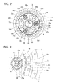
- FIG. 1 shows a cross-sectional view of main parts of a reduction gear transmission 10 of the present embodiment.
- FIG. 2 shows a plan view viewed from the arrow A in the figure with a carrier 38a, an oil seal 34a, an oil seal 18, and a gear part 32a (to be described) removed.
- FIG. 3 shows an expanded view of a region B surrounded by the broken line in FIG. 2 .
- the reduction gear transmission 10 comprises an internal gear 56, a pair of external gears 20a and 20b, carriers 38a and 38b, three crank members 22a, 22c, and 22e, and three cylindrical roller bearings (here, needle bearings) 26a, 26c, and 26e.
- the letters appended to the numbers may be omitted.
- the external gear 20a has a number of teeth differing from the number of teeth of the internal gear 56, and is surrounded by the internal gear 56.
- the external gear 20a is capable of maintaining a meshed state with the internal gear 56 and rotating while revolving orbitally with respect to an axis line 60 of the internal gear 56.
- the external gear 20a is meshed with the internal gear 56 via internal pins 16.
- the internal pin 16 has a cylindrical column shape.
- Six through holes 58a to 58f are formed in the external gear 20a at positions offset from the center of the external gear 20a. Further, a through hole 64 (see FIG. 2 ) is formed in a central portion of the external gear 20a.
- the description of the external gear 20a is also applicable unchanged to the external gear 20b.
- the six through holes of the external gear 20b are represented by 59a to 59f.
- the external gear 20a and the external gear 20b are offset symmetrically with respect to the axis line 60 of the internal gear 56 (see FIG. 1 ). As shown in FIG. 1 , the external gears 20a and 20b mesh with the internal gear 56 via the common internal pins 16.
- the carriers 38a and 38b are supported so as to be capable of rotating around the axis line 60 of the internal gear 56 (see FIG. 2 ) by a pair of angular ball bearings 12a and 12b.
- three column parts 52b, 52d, and 52f are formed on the carrier 38b.
- the column part 52b passes through the through hole 58b of the external gear 20a and the through hole 59b of the external gear 20b.
- a space is maintained between the column part 52b and the through hole 58b that allows the external gear 20a to revolve orbitally around the axis line 60 of the internal gear 56.
- a space is maintained between the column part 52b and the through hole 59b that allows the external gear 20b to revolve orbitally around the axis line 60 of the internal gear 56.
- the column part 52d passes through the through hole 58d of the external gear 20a and the through hole 59d of the external gear 20b.
- a space is maintained between the column part 52d and the through hole 58d that allows the external gear 20a to revolve orbitally around the axis line 60 of the internal gear 56.
- a space is maintained between the column part 52d and the through hole 59d that allows the external gear 20b to revolve orbitally around the axis line 60 of the internal gear 56.
- the column part 52f passes through the through hole 58f of the external gear 20a and the through hole 59f of the external gear 20b.
- a space is maintained between the column part 52f and the through hole 58f that allows the external gear 20a to revolve orbitally around the axis line 60 of the internal gear 56.
- a space is maintained between the column part 52f and the through hole 59f that allows the external gear 20b to revolve orbitally around the axis line 60 of the internal gear 56.
- the carrier 38a is fixed to the carrier 38b by a bolt 40.
- the carrier 38a is first fixed in a predetermined position with respect to the carrier 38b by a position fixing pin 42, and is then fixed by the bolt 40.
- the carriers 38a and 38b are formed above and below the external gears 20a and 20b in the axial direction thereof so as to have the external gears 20a and 20b therebetween.
- the movement of the external gears 20a and 20b in the axial direction (thrust direction) is restricted by the carriers 38a and 38b.
- the carriers 38a and 38b prevent the reduction gear transmission 10 from being distorted in a direction orthogonal to its rotational axis line while the reduction gear transmission 10 is operating. That is, the torsional rigidity of the reduction gear transmission 10 can be increased by the carriers 38a and 38b.
- the column parts 52 pass through the through holes 58 and 59 formed in the external gears 20a and 20b.
- the support pin 24a passes through the through hole 58a of the external gear 20a and the through hole 59a of the external gear 20b.
- the support pin 24c passes through the through hole 58c of the external gear 20a and the through hole 59c of the external gear 20b.
- the support pin 24e passes through the through hole 58e of the external gear 20a and the through hole 59e of the external gear 20b.
- the carrier 38b extends to an outer side of the internal gear 56, and forms a first support part 48.
- a second support part 46 is fixed to the first support part 48 by a bolt 44.
- a support part 50 is formed from the first support part 48 and the second support part 46.
- the pair of angular ball bearings 12a and 12b is arranged in front-facing assembly between the support part 50 and the internal gear 56.
- Front-facing assembly refers to a state in which an outer race of the angular ball bearings 12a and 12b applies pressure to the ball from the outer side in the direction of the axis line 60 of the internal gear 56.
- the support part 50 and the internal gear 56 are allowed to rotate with respect to one another, and their movement with respect to one another in their coaxial direction is restricted by the pair of angular ball bearings 12a and 12b.
- the pair of angular ball bearings 12a and 12b is arranged along almost the entire length of the internal gear 56 in its axial direction. That is, the pair of angular ball bearings 12a and 12b is arranged within the range of the length in the axial direction in which the internal gear 56 and the external gears 20a and 20b mesh.
- the length in the axial direction of the internal gear 56 that does not include the portion thereof that meshes with the external gears 20a and 20b can be reduced by arranging the pair of angular ball bearings 12a and 12b within the aforesaid range of the length in the axial direction in which the internal gear 56 and the external gears 20a and 20b mesh. That is, for the bearings are arranged between the internal gear 56 and the carriers 38a and 38b, it is not necessary to increase length in the direction of the axis line 60 of the internal gear 56.
- angular ball bearings 12a and 12b are arranged by front-facing assembly, the length of the internal gear 56 in the axial direction can be reduced compared to the case in which the angular ball bearings are arranged by rear face assembly.
- rear face assembly refers to a state in which an inner ring of the angular ball bearings 12a and 12b applies pressure to the ball from an outer side in the direction of the axis line 60 of the internal gear 56.
- a gear 30 (an input gear), an eccentric disk 25, and an eccentric disk 27 are formed on the crank members 22.
- the crank member 22a is arranged between the through hole 58a of the external gear 20a, the through hole 59b of the external gear 20b, and the support pin 24a.
- the crank member 22c is arranged between the through hole 58c of the external gear 20a, the through hole 59c of the external gear 20b, and the support pin 24c.
- the crank member 22e is arranged between the through hole 58e of the external gear 20a, the through hole 59e of the external gear 20b, and the support pin 24e.
- the needle bearing 26a is arranged between the support pin 24a and the crank member 22a.
- the crank member 22a is supported by the needle bearing 26a so as to be capable of rotating with respect to the support pin 24a.
- the needle bearing 26c is arranged between the support pin 24c and the crank member 22c.
- the crank member 22c is supported by the needle bearing 26c so as to be capable of rotating with respect to the support pin 24c.
- the needle bearing 26e is arranged between the support pin 24e and the crank member 22e.
- the crank member 22e is supported by the needle bearing 26e so as to be capable of rotating with respect to the support pin 24e.
- a pair of thrust washers 23a and 23b is arranged at both ends in an axial direction of each of the crank members 22, and the thrust washers 23a and 23b prevent rattling of the crank members 22 in the axial direction while the reduction gear transmission 10 is operating.
- the needle bearing 26 is arranged along almost the entire length of the crank member 22 in the axial direction thereof. Arranging the needle bearing 26 within the range of the length in the axial direction in which the eccentric disks 25 and 27 are formed allows the length of the crank member 22 to be reduced, this reduction in length thus not including where the eccentric disks 25 and 27 are formed. That is, for the bearings are arranged between the crank member 22 and the carriers 38a and 38b, it is not necessary to increase the length in the axial direction of the crank member 22.
- the gear 30 of each of the crank members 22 is provided on an axis line that is identical with an axis line 66 (see FIG. 3 ) of the support pin 24, and rotates with respect to the axis line 66.
- the eccentric disks 25 and 27 have a center 65 (see FIG. 3 ) that is offset from the axis line 66 (see FIG. 3 ) of the support pin 24.
- the directions in which the eccentric disks 25 and 27 are offset are opposite directions. That is, the center 65 of the eccentric disk 25 and the center of the eccentric disk 27 are on opposite sides with the axis line 66 (see FIG. 3 ) of the support pin 24 between the two.
- the eccentric disk 25a is fitted into the through hole 58a of the external gear 20a, and the eccentric disk 27a is fitted into the through hole 59a of the external gear 20b.
- the eccentric disk 25c is fitted into the through hole 58c of the external gear 20a, and the eccentric disk 27c is fitted into the through hole 59c of the external gear 20b.
- the eccentric disk 25e is fitted into the through hole 58e of the external gear 20a, and the eccentric disk 27e is fitted into the through hole 59e of the external gear 20b.
- a needle bearing 28a is arranged between the eccentric disk 25a and the through hole 58a of the external gear 20a.
- the needle bearing 28a allows the eccentric disk 25a to rotate at an inner side of the through hole 58a of the external gear 20a.
- a needle bearing 29a is arranged between the eccentric disk 27a and the through hole 59a of the external gear 20b.
- the needle bearing 29a allows the eccentric disk 27a to rotate at an inner side of the through hole 59a of the external gear 20b.
- a needle bearing 28c is arranged between the eccentric disk 25c and the through hole 58c of the external gear 20a.
- the needle bearing 28c allows the eccentric disk 25c to rotate at an inner side of the through hole 58c of the external gear 20a.
- a needle bearing 29c is arranged between the eccentric disk 27c and the through hole 59c of the external gear 20b.
- the needle bearing 29c allows the eccentric disk 27c to rotate at an inner side of the through hole 59c of the external gear 20b.
- a needle bearing 28e is arranged between the eccentric disk 25e and the through hole 58e of the external gear 20a.
- the needle bearing 28e allows the eccentric disk 25e to rotate at an inner side of the through hole 58e of the external gear 20a.
- a needle bearing 29e is arranged between the eccentric disk 27e and the through hole 59e of the external gear 20b. The needle bearing 29e allows the eccentric disk 27e to rotate at an inner side of the through hole 59e of the external gear 20b.
- the eccentric disks 25 and 27 rotate eccentrically. That is, as shown in FIG. 3 , the center 65 of the eccentric disks 25a, 25c, and 25e revolve orbitally with respect to the axis line 66 of the support pins 24a, 24c, and 24e, as shown by the arrow 70. Moreover, the arrow 70 shows only the direction of orbital revolution, and does not accurately show the radius of orbital revolution. The actual radius of orbital revolution is identical with the distance between the center 65 and the axis line 66 (the offset distance).
- the eccentric disks 25a, 25c, and 25e revolve orbitally with respect to the axis line 66
- the external gear 20a revolves orbitally with respect to the internal gear 56 around the axis line 60, as shown by the arrow 62 (see FIG. 2 ).
- the arrow 62 shows only the direction of orbital revolution, and does not accurately show the radius of orbital revolution.
- the actual radius of orbital revolution is identical with the offset distance between the center 65 and the axis line 66. Since the external gear 20a is meshed with the internal gear 56 when the external gear 20a revolves orbitally around the axis line 60, the external gear 20a rotates with respect to the internal gear 56.
- the external gear 20b Since the external gear 20b is meshed with the internal gear 56 when the external gear 20b revolves orbitally with respect to the axis line 60, the external gear 20b rotates with respect to the internal gear 56. When the external gear 20b rotates, the carriers 38a and 38b rotate with respect to the internal gear 56.
- a spur gear 32 is formed at a center portion of the reduction gear transmission 10.
- the spur gear 32 comprises a shaft part 32b, a gear part 32a fixed to an upper part of the shaft part 32b, and a protrusion 55 formed below the shaft part 32b.
- the spur gear 32 passes through the through hole 64 of the external gears 20a and 20b.
- the gear part 32a of the spur gear 32 meshes with the gears 30a, 30c, and 30e formed on the crank members 22a, 22c, and 22e.
- the protrusion 55 is capable of meshing with a spline formed on an output shaft (rotating shaft) of a motor or the like (not shown).
- the protrusion 55 is formed below the shaft part 32b.
- a spur gear or the like may be formed instead of the protrusion 55. What is important here is that a means is formed that transmits the torque of the motor or the like (not shown) to the spur gear 32.
- a through hole 54 is formed in a center portion of the spur gear 32, and wiring or tubing, etc. is capable of passing through the through hole 54.
- a pair of oil seals 34a and 34b is formed between the shaft part 32b of the spur gear 32 and the carriers 38a and 38b. Oil that has been inserted between the spur gear 32 and the crank member 22 can be prevented from leaking to the exterior of the reduction gear transmission 10 by the oil seals 34a and 34b.
- the oil seal 18 is formed between the carrier 38a and the internal gear 56. Oil that has been inserted between the external gears 20a and 20b and the internal gear 56 can be prevented from leaking out of the reduction gear transmission 10 by the oil seal 18.
- An oil seal 14 is formed between the internal gear 56 and the second support part 46 of the support part 50. Oil that has been inserted between the internal gear 56 and the support part 50 can be prevented from leaking out of the reduction gear transmission 10 by the oil seal 14.
- the number of teeth of the external gear 20a is less than the number of teeth of the internal gear 56.
- the external gear 20a is capable of revolving orbitally with respect to the axis line 60 of the internal gear, as shown by the arrow 62.
- the internal pins 16 are not fixed to the internal gear 56.
- the internal pins 16 are arranged within a groove 74 (see FIG. 3 ) formed in the internal gear 56, and are capable of rotating around an axis line 72 (see FIG. 3 ).
- the relationship between the internal pins 16 and the internal gear 56 is the same for each of the fifty-two internal pins 16.
- the external gear 20a rotates in a direction opposite to the arrow 62 while revolving orbitally in the direction of the arrow 62 within the internal gear 56.
- the support pins 24a, 24c, and 24e and the column parts 52b, 52d, and 52f revolve orbitally following the rotation of the external gear 20a. That is, the carriers 38a and 38b (see FIG. 1 ) rotate in the direction opposite to the arrow 62, and act an output part of the reduction gear transmission 10.
- the external gear 20a revolves orbitally in the direction of the arrow 62 within the internal gear 56.
- the internal gear 56 rotates in the direction of the arrow 62.
- the internal gear 56 acts the output part of the reduction gear transmission 10.
- the number of teeth of the internal gear 56 is fifty-two teeth
- the number of teeth of the external gear 20a is fifty-one teeth.
- the internal gear 56 makes one rotation for every fifty-two orbital revolutions of the external gear 20a.
- the internal gear 56 makes one rotation for every fifty-two orbital revolutions of the external gear 20a.
- the description of the external gear 20a is also applicable unchanged to the external gear 20b. Only the direction of being offset from the axis line 66 of the support pin 24a is the opposite direction. In the state shown in FIG. 2 and FIG. 3 , the center 65 of the eccentric disk 25a and the center of the eccentric disk 27a are on opposing sides with the axis line 66 of the support pin 24a positioned between the two. That is, the external gear 20a and the external gear 20b are positioned symmetrically with respect to the support pin 24a, and a relationship is realized in which rotational balance is ensured. Moreover, the relationship of the eccentric disks 27c and 27e with the support pins 24c and the 24e respectively have a relationship identical with that between the eccentric disk 27a and the support pin 24a.
- the gear part 32a of the spur gear 32 is rotated around the axis line 60 of the internal gear 56 via the protrusion 55 formed on the spur gear 32. That is, the rotation speed of the gear part 32a is the same as the rotation speed of the output shaft of the motor or the like.
- the rotation transmitted to the gear part 32a is transmitted to the gear 30 formed on the crank member 22.
- the rotation speed of the output shaft of the motor or the like can be changed by adjusting the number of teeth of the gear part 32a and the number of teeth of the gear 30. That is, the rotation speed of the output shaft of the motor or the like can be both decreased and increased.
- the rotation speed of the output shaft of the motor or the like can also remain unchanged by having the number of teeth of the gear part 32a and the number of teeth of the gear 30 be identical.
- the eccentric disks 25 and 27 of the crank member 22 revolve orbitally around the axis line 66 of the support pin 24 (see FIG. 3 ).
- the eccentric disks 25 and 27 revolve orbitally, the external gears 20a and 20b revolve orbitally in the direction of the arrow 62 (see FIG. 2 ) while in a meshed state with the internal gear 56 via the internal pins 16.
- the rotation of the internal gear 56 is restricted, the external gears 20a and 20b rotate while revolving orbitally under a meshed state with the internal gear 56.
- the carriers 30a and 30b rotate with respect to the axis line 60.
- the rotation of the external gears 20a and 20b is restricted, the external gears 20a and 20b revolve orbitally in the direction of the arrow 62 while in a meshed state with the internal gear 56.
- the internal gear 56 rotates with respect to the axis line 60 in the direction of the arrow 62.
- the ratio between the rotation speed of the crank shaft 22 and the rotation speed of the output part of the reduction gear transmission 10 can be changed by adjusting the number of teeth of the internal gear 56 and the external gears 20a and 20b.
- FIG. 4 shows a cross-sectional view of main parts of another reduction gear transmission 100 of the present invention.
- the thrust washers 23a and 23b that are utilized in the reduction gear transmission 10 are not utilized in the reduction gear transmission 100.
- the crank member 22 is arranged between the through hole 58 of the external gear 20a, the through hole 59 of the external gear 20b, and a support pin 124.
- a pair of bearings (here, tapered roller bearings) 126a and 126b is arranged between the support pin 124 and the crank member 22.
- the crank member 22 is supported by the pair of bearings 126a and 126b such that the crank member 22 is capable of rotating with respect to the support pin 124 and the movement of the crank member 22 in an axial direction is restricted.
- the pair of tapered roller bearings 126a and 126b can apply pressure in a direction orthogonal to the axial direction between the support pin 124 and the crank member 22. Rattling of the crank member 22 with respect to an axis line of the support pin 124 can thereby be suppressed while the reduction gear transmission 100 is operating.
- the pair of tapered roller bearings 126a and 126b is arranged along approximately the entire length in the axial direction of the crank member 22.
- the tapered roller bearings 126a and 126b are arranged within a range of the length in the axial direction in which the eccentric disks 25 and 27 are formed.
- the length of the crank member 22 can be reduced, this reduction in length excluding where the eccentric disks 25 and 27 are formed.
- FIG. 5 shows a cross-sectional view of main parts of a joint part 200 of an industrial robot utilizing the reduction gear transmission 10 of the present invention.
- the joint part 200 comprises a front step arm 82, a back step arm 78, and the reduction gear transmission 10.
- the front step arm 82 is fixed to the support part 50 of the reduction gear transmission 10 by a bolt 80.
- the back step arm 78 is fixed to the internal gear 56 of the reduction gear transmission 10 by a bolt 76.
- a hole 86 is formed in the front step arm 82 and a hole 88 is formed in the back step arm 78. The hole 86, the hole 88, and the hole 54 of the spur gear 32 communicate.
- a member for transmitting rotation to another reduction gear transmission or wiring can pass through the interior of the holes 86, 88, and 54.
- the back step arm 78 is capable of rotating with respect to the front step arm 82 with respect to an axis line CL.
- a motor or the like that is capable of outputting rotation is arranged within a space 84. The rotation of an output part of the motor or the like is transmitted to the protrusion 55 of the reduction gear transmission 10.
- the internal gear 56 is caused to rotate with respect to the support part 50 by the rotation of the protrusion 55.
- the back step arm 78 can be caused by the rotation of the internal gear 56 to rotate with respect to the front step arm 82 with respect to the axis line CL.
- the carriers form support parts that extend to the outer side of the internal gear.
- the internal gear is capable of rotating with respect to the support parts, and its movement in the axial direction is restricted.
- it need not necessarily be carriers that form the support parts that extend to the outer side of the internal gear.
- the internal gear may be capable of rotating with respect to a carrier at an inner side of the internal gear, and its movement in the axial direction may be restricted.
- the bearing may be arranged between the internal gear and the carrier, avoiding the portion where the internal gear and the external gear mesh.
- the through holes are formed in the center of the external gear, the center of the carrier, and the center of the spur gear.
- through holes are not necessarily required in the case where wiring, etc. is not passed through the interior of the reduction gear transmission. That is, the through holes may be formed in accordance with the aim and intended use of the reduction gear transmission.
- a part of the carrier passes through the through hole formed in the external gear.
- the part of the carrier may equally well not pass through the through hole formed in the external gear.
- the support pin fixed to the carrier passes through the through hole formed in the external gear.
- the support pin rotates following the rotation of the external gear.
- the carrier rotates following the rotation of the external gear.
- three crank members have been formed, and the torque of the motor or the like is transmitted simultaneously to the three crank members via the spur gear.
- the number of crank members is not restricted to three.
- the torque of the motor or the like can be transmitted directly to one crank member out of the plurality of crank members.
- the method of transmitting the torque of the motor or the like to the crank member may be selected in accordance with the type of motor or the like utilized.
- two external gears are utilized, and these are offset symmetrically with respect to the axis line of the internal gear.
- the number of external gears is not restricted to two.
- the number of external gears may be one, or may be three or more. Decreasing the number of external gears contributes to decreasing the length of the reduction gear transmission along its rotational axis line direction. Increasing the number of number of external gears improves the rotational balance of the reduction gear transmission.
- the number of number of external gears can be selected in accordance with the aim and intended use of the reduction gear transmission.
- the technological components described in the present specification or drawings exhibit technological utility either individually or in various combinations, and are not limited to the combinations disclosed in the claims at the time of application. Furthermore, the technology illustrated in the present specification or the drawings may simultaneously achieve a plurality of objects, and has technological utility by achieving one of those objects.
Landscapes
- Engineering & Computer Science (AREA)
- General Engineering & Computer Science (AREA)
- Mechanical Engineering (AREA)
- Retarders (AREA)
Abstract
Description
- The present application claims priority to Japanese Patent Application No.
2006-163263 filed on June 13, 2006
The present invention relates to a reduction gear transmission utilized in an industrial robot or a machinery tool, etc. In particular, the present invention relates to a technique for shortening the length in the direction of a rotational axis line of the reduction gear transmission. - In a case where an external gear having a number of teeth differing from the number of teeth of an internal gear is disposed inside the internal gear while the external gear is in a meshed state with the internal gear and the external gear is made to revolve orbitally around an axis line of the internal gear while maintaining the meshed state, the external gear rotates with respect to the internal gear. Inner meshing planetary gear type reduction gear transmissions utilizing this mechanism have been developed, and an example thereof is disclosed in Japanese Patent Application Publication No.
2000-154849
The external gear has a number of teeth differing from a number of teeth of the internal gear, and is surrounded by the internal gear. The external gear rotates while revolving orbitally with respect to the axis line of the internal gear while maintaining a meshed state with the internal gear. A plurality of through holes are formed in the external gear at positions offset from a center of the external gear.
A carrier is supported such that the carrier is capable of rotating with respect to the axis line of the internal gear. Further, a part of the carrier passes through some of the through holes formed in the external gear. A space is maintained between the through hole and the carrier. As a result, the carrier allows the external gear to revolve orbitally with respect to the axis line of the carrier, and the carrier rotates following the rotation of the external gear.
The crankshaft comprises a shaft part capable of rotating with respect to the carrier, an input gear fixed to the shaft part and capable of causing the shaft part to rotate, and an eccentric disk fixed to the shaft part and having its center at a position offset from an axis line of the shaft part. The eccentric disk of the crankshaft is fitted into the other through holes (the through holes into which the carrier is not inserted) of the external gear.
The bearing is arranged between the carrier and the shaft part of the crankshaft. Further, the bearing supports the shaft part of the crankshaft such that the shaft part is capable of rotating with respect to the carrier.
The eccentric disk of the crankshaft rotates eccentrically following the rotation of the input gear of the crankshaft. When the eccentric disk of the crankshaft rotates eccentrically, the external gear rotates while revolving orbitally with respect to the internal gear. When the external gear rotates, the carrier rotates with respect to the internal gear. - In the inner meshing planetary gear type reduction gear transmission, the crankshaft must be capable of rotating with respect to the carrier. In the conventional reduction gear transmission described above, the shaft part is formed so as to extend from the eccentric disk toward both sides in an axial direction of the crankshaft. This shaft part is supported with respect to the carrier by cylindrical roller bearings. That is, in the conventional reduction gear transmission, the shaft part is provided that extends from the eccentric disk toward both sides in the axial direction, and this shaft part must be supported by the bearings. As a result, the crankshaft becomes longer in its axial direction. The reduction gear transmission consequently becomes longer in its rotational axis line direction.
- A reduction gear transmission may be embedded in, for example, a joint portion of an industrial robot. The joint portion of the industrial robot cannot be made more compact if the reduction gear transmission is long in its rotational axis line direction. Since the reduction gear transmission is embedded in the industrial robot or a machinery tool, it is desirable for the reduction gear transmission to be made shorter in its rotational axis line direction. In the present invention, a technique is realized whereby a reduction gear transmission is made shorter in its rotational axis line direction.
- The reduction gear transmission of the present invention comprises at least an internal gear, an external gear, a carrier, a crank member, and a bearing. The external gear has a number of teeth differing from a number of teeth of the internal gear, and is surrounded by the internal gear. The external gear is capable of rotating while revolving orbitally with respect to an axis line of the internal gear while maintaining the meshed state with the internal gear. Further, a through hole is formed in the external gear at a position offset from a center of the external gear. The carrier is supported such that the carrier is capable of rotating with respect to the axis line of the internal gear. Further, the carrier has a support pin passing through the through hole of the external gear. In the reduction gear transmission of the present invention, a crank member is utilized instead of the crankshaft that has been conventionally utilized. The crank member is arranged between the through hole of the external gear and the support pin of the carrier. The crank member comprises an input gear that rotates with respect to the support pin, and an eccentric disk whose center is offset from an axis line of the support pin. The eccentric disk of the crank member is fitted into the through hole of the external gear. The bearing is arranged between the crank member and the support pin of the carrier. The crank member is supported by the bearing such that the crank member is capable of rotating with respect to the support pin of the carrier.
In the reduction gear transmission of the present invention, the eccentric disk formed in the crank member rotates eccentrically when the input gear of the crank member rotates. The external gear revolves orbitally with respect to the axis line of the internal gear when the eccentric disk rotates eccentrically. Further, the external gear rotates with respect to the internal gear while revolving orbitally with respect to the axis line of the internal gear. When the external gear rotates with respect to the internal gear, the carrier rotates with respect to the internal gear. - In the reduction gear transmission described above, the bearing is arranged between the crank member and the support pin of the carrier, and the crank member is supported such that the crank member is capable of rotating with respect to the support pin. The crank member is supported by the bearing such that the crank member is capable of rotating with respect to the carrier. According to the reduction gear transmission described above, the length of the crank member can be shortened in the axial direction. That is, it is no longer necessary to provide bearings at both ends of the eccentric disk in the axial direction in order to support the crank member so as to be capable of rotating with respect to the carrier. Furthermore, it is no longer necessary to maintain a length on the crank member that is exclusively for providing the bearings. According to the reduction gear transmission described above, the crank member can be made shorter in the axial direction. As a result, the reduction gear transmission can be made more compact in its rotational axis line direction.
- In the reduction gear transmission of the present invention, it is preferred that at least a part of the bearing is positioned within a range in which the eccentric disk is arranged along an axial direction of the crank member.
According to the reduction gear transmission described above, the bearing can be disposed inside the through hole of the external gear into which the eccentric disk is fitted, and it is thereby possible to reduce the length of the crank member in the axial direction, except for the length of the eccentric disk. It is more preferred that the bearing is positioned only within the range in which the eccentric disk is arranged along the axis line of the crank member, or positioned only within the range in which the eccentric disk and the input gear are formed. That is, the crank member can be simply composed with just the eccentric disk and the input gear. The length of the reduction gear transmission can be reduced in the rotational axis line direction by minimizing the length of the crank member in the axial direction. - In one embodiment of the reduction gear transmission of the present invention, a cylindrical roller bearing may be provided between the crank member and the support pin formed on the carrier. Furthermore, restriction members that restrict the movement of the crank member in the axial direction with respect to the support pin may be provided, whereas the respective restriction members are arranged at each end of the crank member in an axial direction of the crank member.
According to the reduction gear transmission described above, the crank member is not only supported so as to be capable of rotating with respect to the support pin, but the movement of the crank member in the axial direction is also restricted. The crank member can be prevented from rattling in the axial direction while the reduction gear transmission is operating. Further, for the purpose of the crank member is supported so as to be capable of rotating with respect to the support pin, it is possible to utilize the cylindrical roller bearing. Since the cylindrical roller bearing is an inexpensive type of bearing, the component cost of the reduction gear transmission can be reduced. - In another embodiment of the reduction gear transmission of the present invention, the bearing may be arranged between the crank member and the support pin and allows relative rotation of the crank member and the support pin. This bearing may restrict relative movement of the crank member and the support pin in an axial direction of the crank member and the support pin.
According to the reduction gear transmission described above, providing merely the one type of bearing not only supports the crank member so as to be capable of rotating with respect to the support pin, but also restricts the movement of the crank member in their coaxial direction. The crank member can be prevented from rattling in the axial direction during the operation of the reduction gear transmission without increasing the number of parts that are utilized. - In the reduction gear transmission of the present invention, the reduction gear transmission having been made shorter in its rotational axis line direction can be utilized in conjunction with other techniques. That is, in any of the reduction gear transmissions of the present invention described above, the carrier may extend over the internal gear to the outer side of the internal gear. A bearing may be arranged between the internal gear and an extending portion of the carrier that extends to the outer side of the internal gear. The bearing may allow relative rotation of the carrier and the internal gear. The bearing may also restrict relative movement of the carrier and the internal gear in an axial direction of the carrier and the internal gear.
- According to the reduction gear transmission described above, the internal gear can be shortened in the axial direction. That is, the internal gear no longer needs to have a length for disposing the bearing between the carrier and the internal gear. The bearing can be arranged within the range, along the axis line, in which the internal gear and the external gear mesh. The bearing supports the carrier so as to allow the carrier to rotate with respect to the internal gear and restricts the relative movement of the carrier and the internal gear in the axial direction of the carrier and the internal gear. By shortening the internal gear in the axial direction, the reduction gear transmission can be made shorter in its rotational axis line direction.
A reduction gear transmission is already known in which a carrier extends to an outer side of an internal gear and a bearing is arranged between the internal gear and an extending portion of the carrier that extends to the outer side of the internal gear. However, although the bearing is arranged between the internal gear and the extending portion of the carrier that extends to the outer side of the internal gear in the prior art, this did not reduce the length of the reduction gear transmission in its rotational axis line direction. As described above, in the conventional reduction gear transmission, shaft parts are formed at both ends of the eccentric disk of the crankshaft. The bearings are provided between the shaft parts and the carrier in order for the crankshaft to be supported so as to be capable of rotating with respect to the carrier. In the conventional reduction gear transmission, the length of the reduction gear transmission cannot be reduced in its rotational axis line direction even if the method described above is adopted. This is because the length of the crankshaft in the axial direction does not change. In the conventional reduction gear transmission, it is not meaningful to dispose the bearing between the internal gear and the portion of the carrier that extends to the outer side of the internal gear in order to decrease the length of the reduction gear transmission in its rotational axis line direction. Extending the carrier to the outer side of the internal gear only increases the radius of the reduction transmission. Arranging the bearing between the internal gear and the extending portion of the carrier that extends to the outer side of the internal gear contributes to decreasing the length of the reduction gear transmission in its rotational axis line direction only when the length of the crankshaft (equivalent to the crank member of the present invention) in the axial direction is reduced first. - It is preferred that the reduction gear transmission of the present invention comprises a spur gear that meshes with the input gear and rotates with respect to the axis line of the internal gear. When this spur gear rotates, the input gear revolves orbitally with respect to the axis line of the internal gear while rotating. When the input gear revolves orbitally with respect to the axis line of the internal gear, the support pin that is inserted into the input gear revolves orbitally with respect to the axis line of the internal gear, and the carrier rotates with respect to the axis line of the internal gear following the support pin.
According to the reduction gear transmission described above, the axis line of the internal gear and an axis line of a motor or the like can be disposed coaxially. The layout of the reduction gear transmission and the motor or the like can thus be made more compact. Further, in the case where a plurality of crank members are utilized, the torque of the motor or the like can be transmitted equally to all of the crank members. That is, it is possible to prevent the torque of the motor or the like being applied to only one crank member. Since the load applied to the crank members is distributed, the durability of the crank members increases (the life of the crank members becomes longer). - According to the reduction gear transmission of the present invention, the length of the reduction gear transmission can be shortened in its rotational axis line direction by reducing the length of the crank member in the axial direction.
According to the reduction gear transmission of claim 2, the bearing can be positioned within a range in which the eccentric disk and the external gear engage along the axial direction of the crank member. The crank member is supported by the bearing so as to be capable of rotating with respect to the support pin. As a result, the length of the crank member in the axial direction can be further shortened.
According to the reduction gear transmission of claims 3 and 4, the crank member can be supported so as to be capable of rotating with respect to the support pin, and the movement of the crank member in the axial direction can be restricted. -
-
FIG. 1 shows a cross-sectional view of main parts of a reduction gear transmission of a first embodiment. -
FIG. 2 shows a plan view of the reduction gear transmission of the first embodiment. -
FIG. 3 shows an enlarged view of region B surrounded by the dotted line inFIG. 2 . -
FIG. 4 shows a cross-sectional view of main parts of a reduction gear transmission of a second embodiment. -
FIG. 5 shows a cross-sectional view of main parts of a joint part of an industrial robot utilizing the reduction gear transmission of the first embodiment. - Some of the features of the present embodiments will be described below.
- (Feature 1) A
needle bearing 26 is arranged between asupport pin 24 and a crank member 22. The crank member 22 is supported by theneedle bearing 26 so as to be capable of rotating with respect to thesupport pin 24. A pair ofthrust washers support pin 24 is restricted by thethrust washers - (Feature 2) A
carrier 38b extends over aninternal gear 56 to an outer side of theinternal gear 56, forming afirst support part 48 of asupport part 50. A pair ofangular ball bearings support part 50 and theinternal gear 56. The pair ofangular ball bearings internal gear 56 to rotate with respect to thesupport part 50 and restrict the movement of theinternal gear 56 in an axial direction. - (Feature 3) A
spur gear 32 that meshes with a gear 30 (an input gear) of the crank member 22 is arranged at a central portion of thereduction gear transmission 10. - (Feature 4) Through holes are formed in central portions of
external gears carriers spur gear 32. - (Feature 5) A pair of tapered
roller bearings roller bearings - (Feature 6) The
support part 50 of thereduction gear transmission 10 is connected with afront step arm 82 of arobot arm 200, and theinternal gear 56 of thereduction gear transmission 10 is connected with aback step arm 78. Theback step arm 78 is capable of rotating with respect to thefront step arm 82 around an axis line CL. - Embodiments of the present invention will be described with reference to figures.
-
FIG. 1 shows a cross-sectional view of main parts of areduction gear transmission 10 of the present embodiment.FIG. 2 shows a plan view viewed from the arrow A in the figure with acarrier 38a, anoil seal 34a, anoil seal 18, and agear part 32a (to be described) removed.FIG. 3 shows an expanded view of a region B surrounded by the broken line inFIG. 2 .
Thereduction gear transmission 10 comprises aninternal gear 56, a pair ofexternal gears carriers - As shown in
FIG. 2 , theexternal gear 20a has a number of teeth differing from the number of teeth of theinternal gear 56, and is surrounded by theinternal gear 56. Theexternal gear 20a is capable of maintaining a meshed state with theinternal gear 56 and rotating while revolving orbitally with respect to anaxis line 60 of theinternal gear 56. Theexternal gear 20a is meshed with theinternal gear 56 via internal pins 16. Theinternal pin 16 has a cylindrical column shape. Six throughholes 58a to 58f (seeFIG. 2 ) are formed in theexternal gear 20a at positions offset from the center of theexternal gear 20a. Further, a through hole 64 (seeFIG. 2 ) is formed in a central portion of theexternal gear 20a.
The description of theexternal gear 20a is also applicable unchanged to theexternal gear 20b. The six through holes of theexternal gear 20b are represented by 59a to 59f. Theexternal gear 20a and theexternal gear 20b are offset symmetrically with respect to theaxis line 60 of the internal gear 56 (seeFIG. 1 ).
As shown inFIG. 1 , theexternal gears internal gear 56 via the commoninternal pins 16. - As shown in
FIG. 1 , thecarriers axis line 60 of the internal gear 56 (seeFIG. 2 ) by a pair ofangular ball bearings FIG. 1 andFIG. 2 , threecolumn parts carrier 38b. Thecolumn part 52b passes through the throughhole 58b of theexternal gear 20a and the throughhole 59b of theexternal gear 20b. A space is maintained between thecolumn part 52b and the throughhole 58b that allows theexternal gear 20a to revolve orbitally around theaxis line 60 of theinternal gear 56. A space is maintained between thecolumn part 52b and the throughhole 59b that allows theexternal gear 20b to revolve orbitally around theaxis line 60 of theinternal gear 56. Thecolumn part 52d passes through the throughhole 58d of theexternal gear 20a and the throughhole 59d of theexternal gear 20b. A space is maintained between thecolumn part 52d and the throughhole 58d that allows theexternal gear 20a to revolve orbitally around theaxis line 60 of theinternal gear 56. A space is maintained between thecolumn part 52d and the throughhole 59d that allows theexternal gear 20b to revolve orbitally around theaxis line 60 of theinternal gear 56. Thecolumn part 52f passes through the throughhole 58f of theexternal gear 20a and the throughhole 59f of theexternal gear 20b. A space is maintained between thecolumn part 52f and the throughhole 58f that allows theexternal gear 20a to revolve orbitally around theaxis line 60 of theinternal gear 56. A space is maintained between thecolumn part 52f and the throughhole 59f that allows theexternal gear 20b to revolve orbitally around theaxis line 60 of theinternal gear 56.
As will be described later, since thecarrier 38b rotates around theaxis line 60 of theinternal gear 56, theexternal gears axis line 60 of theinternal gear 56. - The
carrier 38a is fixed to thecarrier 38b by abolt 40. Thecarrier 38a is first fixed in a predetermined position with respect to thecarrier 38b by aposition fixing pin 42, and is then fixed by thebolt 40. Thecarriers external gears external gears external gears carriers carriers reduction gear transmission 10 from being distorted in a direction orthogonal to its rotational axis line while thereduction gear transmission 10 is operating. That is, the torsional rigidity of thereduction gear transmission 10 can be increased by thecarriers column parts 52 pass through the throughholes external gears - Further, three
support pins carriers support pin 24a passes through the throughhole 58a of theexternal gear 20a and the throughhole 59a of theexternal gear 20b. Thesupport pin 24c passes through the throughhole 58c of theexternal gear 20a and the throughhole 59c of theexternal gear 20b. Thesupport pin 24e passes through the throughhole 58e of theexternal gear 20a and the throughhole 59e of theexternal gear 20b. - The
carrier 38b extends to an outer side of theinternal gear 56, and forms afirst support part 48. Asecond support part 46 is fixed to thefirst support part 48 by abolt 44. Asupport part 50 is formed from thefirst support part 48 and thesecond support part 46. The pair ofangular ball bearings support part 50 and theinternal gear 56. "Front-facing assembly" refers to a state in which an outer race of theangular ball bearings axis line 60 of theinternal gear 56. Thesupport part 50 and theinternal gear 56 are allowed to rotate with respect to one another, and their movement with respect to one another in their coaxial direction is restricted by the pair ofangular ball bearings
The pair ofangular ball bearings internal gear 56 in its axial direction. That is, the pair ofangular ball bearings internal gear 56 and theexternal gears internal gear 56 that does not include the portion thereof that meshes with theexternal gears angular ball bearings internal gear 56 and theexternal gears internal gear 56 and thecarriers axis line 60 of theinternal gear 56. Further, since theangular ball bearings internal gear 56 in the axial direction can be reduced compared to the case in which the angular ball bearings are arranged by rear face assembly. Moreover, "rear face assembly" refers to a state in which an inner ring of theangular ball bearings axis line 60 of theinternal gear 56. - As shown in
FIG. 1 , a gear 30 (an input gear), aneccentric disk 25, and aneccentric disk 27 are formed on the crank members 22. The crank member 22a is arranged between the throughhole 58a of theexternal gear 20a, the throughhole 59b of theexternal gear 20b, and thesupport pin 24a. The crank member 22c is arranged between the throughhole 58c of theexternal gear 20a, the throughhole 59c of theexternal gear 20b, and thesupport pin 24c. The crank member 22e is arranged between the throughhole 58e of theexternal gear 20a, the throughhole 59e of theexternal gear 20b, and thesupport pin 24e. - The
needle bearing 26a is arranged between thesupport pin 24a and the crank member 22a. The crank member 22a is supported by theneedle bearing 26a so as to be capable of rotating with respect to thesupport pin 24a. Theneedle bearing 26c is arranged between thesupport pin 24c and the crank member 22c. The crank member 22c is supported by theneedle bearing 26c so as to be capable of rotating with respect to thesupport pin 24c. Theneedle bearing 26e is arranged between thesupport pin 24e and the crank member 22e. The crank member 22e is supported by theneedle bearing 26e so as to be capable of rotating with respect to thesupport pin 24e.
A pair ofthrust washers thrust washers reduction gear transmission 10 is operating.
Theneedle bearing 26 is arranged along almost the entire length of the crank member 22 in the axial direction thereof. Arranging theneedle bearing 26 within the range of the length in the axial direction in which theeccentric disks eccentric disks carriers - The
gear 30 of each of the crank members 22 is provided on an axis line that is identical with an axis line 66 (seeFIG. 3 ) of thesupport pin 24, and rotates with respect to theaxis line 66. When thegear 30 rotates, the crank member 22 rotates with respect to theaxis line 66.
Theeccentric disks FIG. 3 ) that is offset from the axis line 66 (seeFIG. 3 ) of thesupport pin 24. The directions in which theeccentric disks center 65 of theeccentric disk 25 and the center of theeccentric disk 27 are on opposite sides with the axis line 66 (seeFIG. 3 ) of thesupport pin 24 between the two.
Theeccentric disk 25a is fitted into the throughhole 58a of theexternal gear 20a, and theeccentric disk 27a is fitted into the throughhole 59a of theexternal gear 20b. Theeccentric disk 25c is fitted into the throughhole 58c of theexternal gear 20a, and theeccentric disk 27c is fitted into the throughhole 59c of theexternal gear 20b. Theeccentric disk 25e is fitted into the throughhole 58e of theexternal gear 20a, and theeccentric disk 27e is fitted into the throughhole 59e of theexternal gear 20b. - A
needle bearing 28a is arranged between theeccentric disk 25a and the throughhole 58a of theexternal gear 20a. Theneedle bearing 28a allows theeccentric disk 25a to rotate at an inner side of the throughhole 58a of theexternal gear 20a. Aneedle bearing 29a is arranged between theeccentric disk 27a and the throughhole 59a of theexternal gear 20b. Theneedle bearing 29a allows theeccentric disk 27a to rotate at an inner side of the throughhole 59a of theexternal gear 20b.
Aneedle bearing 28c is arranged between theeccentric disk 25c and the throughhole 58c of theexternal gear 20a. Theneedle bearing 28c allows theeccentric disk 25c to rotate at an inner side of the throughhole 58c of theexternal gear 20a. Aneedle bearing 29c is arranged between theeccentric disk 27c and the throughhole 59c of theexternal gear 20b. Theneedle bearing 29c allows theeccentric disk 27c to rotate at an inner side of the throughhole 59c of theexternal gear 20b.
Aneedle bearing 28e is arranged between theeccentric disk 25e and the throughhole 58e of theexternal gear 20a. Theneedle bearing 28e allows theeccentric disk 25e to rotate at an inner side of the throughhole 58e of theexternal gear 20a. Aneedle bearing 29e is arranged between theeccentric disk 27e and the throughhole 59e of theexternal gear 20b. Theneedle bearing 29e allows theeccentric disk 27e to rotate at an inner side of the throughhole 59e of theexternal gear 20b. - When the
gear 30 of the crank members 22 rotates, theeccentric disks FIG. 3 , thecenter 65 of theeccentric disks axis line 66 of the support pins 24a, 24c, and 24e, as shown by thearrow 70. Moreover, thearrow 70 shows only the direction of orbital revolution, and does not accurately show the radius of orbital revolution. The actual radius of orbital revolution is identical with the distance between thecenter 65 and the axis line 66 (the offset distance). When theeccentric disks axis line 66, theexternal gear 20a revolves orbitally with respect to theinternal gear 56 around theaxis line 60, as shown by the arrow 62 (seeFIG. 2 ). Moreover, thearrow 62 shows only the direction of orbital revolution, and does not accurately show the radius of orbital revolution. The actual radius of orbital revolution is identical with the offset distance between thecenter 65 and theaxis line 66.
Since theexternal gear 20a is meshed with theinternal gear 56 when theexternal gear 20a revolves orbitally around theaxis line 60, theexternal gear 20a rotates with respect to theinternal gear 56. When theexternal gear 20a rotates, thecarriers internal gear 56.
Similarly, when thegear 30 of the crank members 22 rotates, thecenter 65 of theeccentric disks axis line 66 of the support pins 24a, 24c, and 24e, as shown by thearrow 70. When theeccentric disks axis line 66, theexternal gear 20b revolves orbitally with respect to theinternal gear 56 around theaxis line 60 of theinternal gear 56, as shown by the arrow 62 (seeFIG. 2 ). Since theexternal gear 20b is meshed with theinternal gear 56 when theexternal gear 20b revolves orbitally with respect to theaxis line 60, theexternal gear 20b rotates with respect to theinternal gear 56. When theexternal gear 20b rotates, thecarriers internal gear 56. - As shown in
FIG. 1 , aspur gear 32 is formed at a center portion of thereduction gear transmission 10. Thespur gear 32 comprises ashaft part 32b, agear part 32a fixed to an upper part of theshaft part 32b, and aprotrusion 55 formed below theshaft part 32b. As shown inFIG. 2 , thespur gear 32 passes through the throughhole 64 of theexternal gears gear part 32a of thespur gear 32 meshes with thegears protrusion 55 is capable of meshing with a spline formed on an output shaft (rotating shaft) of a motor or the like (not shown). In the present embodiment, theprotrusion 55 is formed below theshaft part 32b. However, a spur gear or the like may be formed instead of theprotrusion 55. What is important here is that a means is formed that transmits the torque of the motor or the like (not shown) to thespur gear 32. A throughhole 54 is formed in a center portion of thespur gear 32, and wiring or tubing, etc. is capable of passing through the throughhole 54. - A pair of
oil seals shaft part 32b of thespur gear 32 and thecarriers spur gear 32 and the crank member 22 can be prevented from leaking to the exterior of thereduction gear transmission 10 by the oil seals 34a and 34b. Theoil seal 18 is formed between thecarrier 38a and theinternal gear 56. Oil that has been inserted between theexternal gears internal gear 56 can be prevented from leaking out of thereduction gear transmission 10 by theoil seal 18. Anoil seal 14 is formed between theinternal gear 56 and thesecond support part 46 of thesupport part 50. Oil that has been inserted between theinternal gear 56 and thesupport part 50 can be prevented from leaking out of thereduction gear transmission 10 by theoil seal 14. - As shown in
FIG. 2 , the number of teeth of theexternal gear 20a is less than the number of teeth of theinternal gear 56. When the external teeth in the circumference direction of theexternal gear 20a are in an engaged state with theinternal pins 16 in the circumference direction of theinternal gear 56, theexternal gear 20a is capable of revolving orbitally with respect to theaxis line 60 of the internal gear, as shown by thearrow 62. The internal pins 16 are not fixed to theinternal gear 56. The internal pins 16 are arranged within a groove 74 (seeFIG. 3 ) formed in theinternal gear 56, and are capable of rotating around an axis line 72 (seeFIG. 3 ). The relationship between theinternal pins 16 and theinternal gear 56 is the same for each of the fifty-twointernal pins 16.
When the rotation of theinternal gear 56 is restricted, theexternal gear 20a rotates in a direction opposite to thearrow 62 while revolving orbitally in the direction of thearrow 62 within theinternal gear 56. When theexternal gear 20a rotates, the support pins 24a, 24c, and 24e and thecolumn parts external gear 20a. That is, thecarriers FIG. 1 ) rotate in the direction opposite to thearrow 62, and act an output part of thereduction gear transmission 10. On the other hand, when the rotation of theexternal gear 20a is restricted, theexternal gear 20a revolves orbitally in the direction of thearrow 62 within theinternal gear 56. When theexternal gear 20a revolves orbitally, theinternal gear 56 rotates in the direction of thearrow 62. Theinternal gear 56 acts the output part of thereduction gear transmission 10. When the rotation of theexternal gear 20a is restricted, thecarriers
In the present embodiment, the number of teeth of theinternal gear 56 is fifty-two teeth, and the number of teeth of theexternal gear 20a is fifty-one teeth. As a result, when the rotation of theinternal gear 56 is restricted, theexternal gear 20a makes one rotation for every fifty-two orbital revolutions of theexternal gear 20a. On the other hand, when the rotation of theexternal gear 20a is restricted, theinternal gear 56 makes one rotation for every fifty-two orbital revolutions of theexternal gear 20a. - The description of the
external gear 20a is also applicable unchanged to theexternal gear 20b. Only the direction of being offset from theaxis line 66 of thesupport pin 24a is the opposite direction. In the state shown inFIG. 2 and FIG. 3 , thecenter 65 of theeccentric disk 25a and the center of theeccentric disk 27a are on opposing sides with theaxis line 66 of thesupport pin 24a positioned between the two. That is, theexternal gear 20a and theexternal gear 20b are positioned symmetrically with respect to thesupport pin 24a, and a relationship is realized in which rotational balance is ensured. Moreover, the relationship of theeccentric disks eccentric disk 27a and thesupport pin 24a. - In the
reduction gear transmission 10 of the present embodiment, when the output shaft of the motor or the like (not shown) rotates, thegear part 32a of thespur gear 32 is rotated around theaxis line 60 of theinternal gear 56 via theprotrusion 55 formed on thespur gear 32. That is, the rotation speed of thegear part 32a is the same as the rotation speed of the output shaft of the motor or the like. The rotation transmitted to thegear part 32a is transmitted to thegear 30 formed on the crank member 22. The rotation speed of the output shaft of the motor or the like can be changed by adjusting the number of teeth of thegear part 32a and the number of teeth of thegear 30. That is, the rotation speed of the output shaft of the motor or the like can be both decreased and increased. The rotation speed of the output shaft of the motor or the like can also remain unchanged by having the number of teeth of thegear part 32a and the number of teeth of thegear 30 be identical.
When the crank member 22 rotates, theeccentric disks axis line 66 of the support pin 24 (seeFIG. 3 ). When theeccentric disks external gears FIG. 2 ) while in a meshed state with theinternal gear 56 via the internal pins 16. When the rotation of theinternal gear 56 is restricted, theexternal gears internal gear 56. When theexternal gears carriers 30a and 30b rotate with respect to theaxis line 60. When the rotation of theexternal gears external gears arrow 62 while in a meshed state with theinternal gear 56. When theexternal gears internal gear 56 rotates with respect to theaxis line 60 in the direction of thearrow 62.
The ratio between the rotation speed of the crank shaft 22 and the rotation speed of the output part of thereduction gear transmission 10 can be changed by adjusting the number of teeth of theinternal gear 56 and theexternal gears -
FIG. 4 shows a cross-sectional view of main parts of anotherreduction gear transmission 100 of the present invention. Here, only parts differing from the first embodiment will be described. Components that are the same as in the first embodiment will have the same reference numbers applied thereto and an explanation thereof will be omitted.
Thethrust washers reduction gear transmission 10 are not utilized in thereduction gear transmission 100. The crank member 22 is arranged between the throughhole 58 of theexternal gear 20a, the throughhole 59 of theexternal gear 20b, and a support pin 124. A pair of bearings (here, tapered roller bearings) 126a and 126b is arranged between the support pin 124 and the crank member 22. The crank member 22 is supported by the pair ofbearings roller bearings reduction gear transmission 100 is operating. Further, the pair of taperedroller bearings roller bearings eccentric disks eccentric disks -
FIG. 5 shows a cross-sectional view of main parts of ajoint part 200 of an industrial robot utilizing thereduction gear transmission 10 of the present invention. Thejoint part 200 comprises afront step arm 82, aback step arm 78, and thereduction gear transmission 10. Thefront step arm 82 is fixed to thesupport part 50 of thereduction gear transmission 10 by abolt 80. Theback step arm 78 is fixed to theinternal gear 56 of thereduction gear transmission 10 by abolt 76. Ahole 86 is formed in thefront step arm 82 and ahole 88 is formed in theback step arm 78. Thehole 86, thehole 88, and thehole 54 of thespur gear 32 communicate. A member for transmitting rotation to another reduction gear transmission or wiring can pass through the interior of theholes back step arm 78 is capable of rotating with respect to thefront step arm 82 with respect to an axis line CL.
A motor or the like that is capable of outputting rotation is arranged within aspace 84. The rotation of an output part of the motor or the like is transmitted to theprotrusion 55 of thereduction gear transmission 10. Theinternal gear 56 is caused to rotate with respect to thesupport part 50 by the rotation of theprotrusion 55. Theback step arm 78 can be caused by the rotation of theinternal gear 56 to rotate with respect to thefront step arm 82 with respect to the axis line CL. - Specific examples of the present invention have been described in detail above. However, these examples are merely illustrations, and do not limit the scope of the claims. The technology described in the patent claims also encompasses various changes and modifications to the specific examples described above.
For example, in the embodiments described above, the carriers form support parts that extend to the outer side of the internal gear. The internal gear is capable of rotating with respect to the support parts, and its movement in the axial direction is restricted. However, it need not necessarily be carriers that form the support parts that extend to the outer side of the internal gear. The internal gear may be capable of rotating with respect to a carrier at an inner side of the internal gear, and its movement in the axial direction may be restricted. In this case, the bearing may be arranged between the internal gear and the carrier, avoiding the portion where the internal gear and the external gear mesh.
In the embodiments described above, the through holes are formed in the center of the external gear, the center of the carrier, and the center of the spur gear. However, through holes are not necessarily required in the case where wiring, etc. is not passed through the interior of the reduction gear transmission. That is, the through holes may be formed in accordance with the aim and intended use of the reduction gear transmission.
In the embodiments, a part of the carrier passes through the through hole formed in the external gear. The part of the carrier may equally well not pass through the through hole formed in the external gear. In the present invention, the support pin fixed to the carrier passes through the through hole formed in the external gear. That is, when the external gear rotates, the support pin rotates following the rotation of the external gear. As a result, the carrier rotates following the rotation of the external gear.
In the embodiments described above, three crank members have been formed, and the torque of the motor or the like is transmitted simultaneously to the three crank members via the spur gear. However, the number of crank members is not restricted to three. Furthermore, the torque of the motor or the like can be transmitted directly to one crank member out of the plurality of crank members. The method of transmitting the torque of the motor or the like to the crank member may be selected in accordance with the type of motor or the like utilized.
In the embodiments described above, two external gears are utilized, and these are offset symmetrically with respect to the axis line of the internal gear. However, the number of external gears is not restricted to two. The number of external gears may be one, or may be three or more. Decreasing the number of external gears contributes to decreasing the length of the reduction gear transmission along its rotational axis line direction. Increasing the number of number of external gears improves the rotational balance of the reduction gear transmission. The number of number of external gears can be selected in accordance with the aim and intended use of the reduction gear transmission.
The technological components described in the present specification or drawings exhibit technological utility either individually or in various combinations, and are not limited to the combinations disclosed in the claims at the time of application. Furthermore, the technology illustrated in the present specification or the drawings may simultaneously achieve a plurality of objects, and has technological utility by achieving one of those objects.
Claims (6)
- A reduction gear transmission at least comprising:an internal gear;an external gear;a carrier;a crank member; anda bearing, whereinthe external gear has a number of teeth differing from a number of teeth of the internal gear and a through hole at a position offset from a center of the external gear, the external gear is surrounded by the internal gear and is capable of rotating while revolving orbitally with respect to an axis line of the internal gear and being meshed with the internal gear,the carrier is supported such that the carrier is capable of rotating with respect to the axis line of the internal gear, and has a support pin passing through the through hole of the external gear,the crank member is arranged between the through hole of the external gear and the support pin of the carrier, and comprises an input gear that rotates with respect to the support pin and an eccentric disk that is fitted into the through hole of the external gear, wherein a center of the eccentric disk is offset from an axis line of the support pin,the bearing is arranged between the crank member and the support pin of the carrier and supports the crank member such that the crank member is capable of rotating with respect to the support pin of the carrier, andin accordance with the rotation of the input gear of the crank member, the eccentric disk rotates eccentrically, the external gear revolves orbitally and rotates with respect to the internal gear, and the carrier rotates with respect to the internal gear.
- The reduction gear transmission according to claim 1, wherein at least a part of the bearing is positioned within a range in which the eccentric disk is arranged along an axial direction of the crank member.
- The reduction gear transmission according to claim 1 or 2, further comprising restriction members that restrict the movement of the crank member in the axial direction of the crank member, wherein
the respective restriction members are arranged at each end of the crank member in the axial direction of the crank member, and the bearing is a type of cylindrical roller bearing. - The reduction gear transmission according to claim 1 or 2, wherein the bearing that is arranged between the crank member and the support pin of the carrier allows relative rotation of the support pin and the crank member and restricts relative movement of the support pin and the crank member in an axial direction of the support pin and the crank member.
- The reduction gear transmission according to any one of claims 1 to 4, further comprising a bearing that is arranged between the internal gear and an extending portion of the carrier that extends to an outer side of the internal gear, wherein the bearing allows relative rotation of the carrier and the internal gear and restricts relative movement of the carrier and the internal gear in an axial direction of the carrier and the internal gear.
- The reduction gear transmission according to any one of claims 1 to 5, further comprising a spur gear that meshes with the input gear and rotates with respect to the axis line of the internal gear; wherein
rotation of the spur gear causes the input gear to rotate while orbitally revolving with respect to the axis line of the internal gear, and
the carrier is caused to rotate, by the support pin inserted in the input gear, following the orbital revolution of the input gear.
Applications Claiming Priority (2)
| Application Number | Priority Date | Filing Date | Title |
|---|---|---|---|
| JP2006163263 | 2006-06-13 | ||
| PCT/JP2007/061716 WO2007145162A1 (en) | 2006-06-13 | 2007-06-11 | Reduction gear |
Publications (3)
| Publication Number | Publication Date |
|---|---|
| EP2034219A1 true EP2034219A1 (en) | 2009-03-11 |
| EP2034219A4 EP2034219A4 (en) | 2010-04-14 |
| EP2034219B1 EP2034219B1 (en) | 2011-10-26 |
Family
ID=38831676
Family Applications (1)
| Application Number | Title | Priority Date | Filing Date |
|---|---|---|---|
| EP07745006A Active EP2034219B1 (en) | 2006-06-13 | 2007-06-11 | Reduction gear |
Country Status (6)
| Country | Link |
|---|---|
| US (1) | US8323140B2 (en) |
| EP (1) | EP2034219B1 (en) |
| JP (2) | JP5122450B2 (en) |
| KR (1) | KR101343669B1 (en) |
| CN (1) | CN101466967B (en) |
| WO (1) | WO2007145162A1 (en) |
Cited By (3)
| Publication number | Priority date | Publication date | Assignee | Title |
|---|---|---|---|---|
| CN103270336A (en) * | 2010-12-22 | 2013-08-28 | 纳博特斯克有限公司 | Gear transmission device |
| EP3483473A1 (en) * | 2017-11-14 | 2019-05-15 | Kimex Group s.r.o. | Gearbox |
| DE102017126737A1 (en) * | 2017-11-14 | 2019-05-16 | Kimex Group s.r.o. | transmission |
Families Citing this family (16)
| Publication number | Priority date | Publication date | Assignee | Title |
|---|---|---|---|---|
| US9879760B2 (en) | 2002-11-25 | 2018-01-30 | Delbert Tesar | Rotary actuator with shortest force path configuration |
| JP5145099B2 (en) * | 2008-03-28 | 2013-02-13 | ナブテスコ株式会社 | Sealed device |
| JP2010007830A (en) * | 2008-06-30 | 2010-01-14 | Nabtesco Corp | Gear device |
| CN102734388B (en) * | 2011-04-12 | 2015-09-02 | 住友重机械工业株式会社 | There is speed change gear series and the gear structure series of gear structure body |
| JP5782321B2 (en) * | 2011-07-15 | 2015-09-24 | ナブテスコ株式会社 | Gear device |
| US10414271B2 (en) | 2013-03-01 | 2019-09-17 | Delbert Tesar | Multi-speed hub drive wheels |
| US9862263B2 (en) | 2013-03-01 | 2018-01-09 | Delbert Tesar | Multi-speed hub drive wheels |
| US9365105B2 (en) | 2013-10-11 | 2016-06-14 | Delbert Tesar | Gear train and clutch designs for multi-speed hub drives |
| US10422387B2 (en) | 2014-05-16 | 2019-09-24 | Delbert Tesar | Quick change interface for low complexity rotary actuator |
| US9657813B2 (en) | 2014-06-06 | 2017-05-23 | Delbert Tesar | Modified parallel eccentric rotary actuator |
| US9915319B2 (en) | 2014-09-29 | 2018-03-13 | Delbert Tesar | Compact parallel eccentric rotary actuator |
| US11014658B1 (en) | 2015-01-02 | 2021-05-25 | Delbert Tesar | Driveline architecture for rotorcraft featuring active response actuators |
| JP6758845B2 (en) * | 2016-02-12 | 2020-09-23 | 住友重機械工業株式会社 | Eccentric swing type gear device |
| US10464413B2 (en) | 2016-06-24 | 2019-11-05 | Delbert Tesar | Electric multi-speed hub drive wheels |
| JP6752070B2 (en) * | 2016-07-12 | 2020-09-09 | ナブテスコ株式会社 | Gear device |
| CN112112940B (en) * | 2019-06-21 | 2022-03-29 | 宁波瀚晟传动技术有限公司 | Transmission mechanism |
Citations (4)
| Publication number | Priority date | Publication date | Assignee | Title |
|---|---|---|---|---|
| US3129611A (en) * | 1960-10-14 | 1964-04-21 | Lee Engineering Company | Speed reducers |
| US20010044356A1 (en) * | 2000-05-15 | 2001-11-22 | Teijin Seiki Co., Ltd. | Eccentric orbiting type speed reducer and joint for industrial machine equipped with the same |
| EP1296084A2 (en) * | 2001-09-13 | 2003-03-26 | Teijin Seiki Co., Ltd. | Eccentric oscillating-type speed reducer |
| EP1662138A1 (en) * | 2003-08-12 | 2006-05-31 | Nabtesco Corporation | Speed reducer for use in yaw drive apparatus for wind power generation apparatus, and yaw drive method and apparatus for wind power generation apparatus using the speed reducer |
Family Cites Families (20)
| Publication number | Priority date | Publication date | Assignee | Title |
|---|---|---|---|---|
| JPS593048U (en) * | 1982-06-30 | 1984-01-10 | 株式会社小松製作所 | reducer device |
| US4846018A (en) * | 1985-03-18 | 1989-07-11 | Teijin Seiki Co., Ltd. | Articulation drive apparatus of industrial robot |
| JPS63135046U (en) * | 1987-02-26 | 1988-09-05 | ||
| JPH05346142A (en) * | 1990-12-25 | 1993-12-27 | Sumitomo Heavy Ind Ltd | Internal engaging type epicycle reduction gear used for rotation control device |
| FR2684154A1 (en) * | 1991-11-21 | 1993-05-28 | Staubli Sa Ets | CYCLOUIDAL SPEED REDUCER FOR ROBOTS AND OTHER INDUSTRIAL MANIPULATORS. |
| FR2684155B1 (en) | 1991-11-21 | 1994-03-18 | Staubli Ets | CYCLOUIDAL SPEED REDUCER FOR ROBOTS AND OTHER INDUSTRIAL MANIPULATORS. |
| US5322485A (en) * | 1991-12-24 | 1994-06-21 | Sumitomo Heavy Industries Ltd. | Internally meshing planetary gear structure |
| SK405092A3 (en) * | 1992-12-31 | 1995-09-13 | Jozef Herstek | Multisatelit gear box |
| JPH10231913A (en) * | 1997-02-18 | 1998-09-02 | Kenji Mimura | Continuously variable transmission |
| JP2000154849A (en) | 1998-11-19 | 2000-06-06 | Teijin Seiki Co Ltd | Reduction and device provided with gear |
| JP3650536B2 (en) * | 1998-12-14 | 2005-05-18 | 住友重機械工業株式会社 | Inscribed mesh planetary gear structure |
| JP4020560B2 (en) | 2000-02-07 | 2007-12-12 | ナブテスコ株式会社 | Eccentric rocking speed reducer |
| KR100301120B1 (en) * | 2000-04-27 | 2001-09-22 | 박용수 | Reducer having an internal planetary gear |
| JP4758020B2 (en) * | 2001-03-30 | 2011-08-24 | 住友重機械工業株式会社 | Axial movement restriction structure of planetary member of reduction gear |
| JP2003343662A (en) * | 2002-05-31 | 2003-12-03 | Komatsu Ltd | Reduction gear and its assembling method |
| JP4726185B2 (en) * | 2004-01-13 | 2011-07-20 | ナブテスコ株式会社 | Eccentric oscillating gear unit |
| CN2744893Y (en) * | 2004-11-29 | 2005-12-07 | 天津大学 | Double-ring type speed reduction transmission apparatus |
| JP2006163263A (en) | 2004-12-10 | 2006-06-22 | Arisawa Mfg Co Ltd | Transmission type screen |
| JP4818787B2 (en) * | 2006-04-17 | 2011-11-16 | 住友重機械工業株式会社 | Swing intermeshing planetary gear unit |
| JP4847892B2 (en) * | 2007-02-22 | 2011-12-28 | 住友重機械工業株式会社 | Oscillating intermeshing planetary gear device and manufacturing method of eccentric shaft thereof |
-
2007
- 2007-06-11 KR KR1020097000584A patent/KR101343669B1/en active IP Right Grant
- 2007-06-11 EP EP07745006A patent/EP2034219B1/en active Active
- 2007-06-11 US US12/308,165 patent/US8323140B2/en active Active
- 2007-06-11 WO PCT/JP2007/061716 patent/WO2007145162A1/en active Application Filing
- 2007-06-11 CN CN2007800215656A patent/CN101466967B/en active Active
- 2007-06-11 JP JP2008521187A patent/JP5122450B2/en active Active
-
2012
- 2012-08-27 JP JP2012186891A patent/JP5466741B2/en active Active
Patent Citations (4)
| Publication number | Priority date | Publication date | Assignee | Title |
|---|---|---|---|---|
| US3129611A (en) * | 1960-10-14 | 1964-04-21 | Lee Engineering Company | Speed reducers |
| US20010044356A1 (en) * | 2000-05-15 | 2001-11-22 | Teijin Seiki Co., Ltd. | Eccentric orbiting type speed reducer and joint for industrial machine equipped with the same |
| EP1296084A2 (en) * | 2001-09-13 | 2003-03-26 | Teijin Seiki Co., Ltd. | Eccentric oscillating-type speed reducer |
| EP1662138A1 (en) * | 2003-08-12 | 2006-05-31 | Nabtesco Corporation | Speed reducer for use in yaw drive apparatus for wind power generation apparatus, and yaw drive method and apparatus for wind power generation apparatus using the speed reducer |
Non-Patent Citations (1)
| Title |
|---|
| See also references of WO2007145162A1 * |
Cited By (3)
| Publication number | Priority date | Publication date | Assignee | Title |
|---|---|---|---|---|
| CN103270336A (en) * | 2010-12-22 | 2013-08-28 | 纳博特斯克有限公司 | Gear transmission device |
| EP3483473A1 (en) * | 2017-11-14 | 2019-05-15 | Kimex Group s.r.o. | Gearbox |
| DE102017126737A1 (en) * | 2017-11-14 | 2019-05-16 | Kimex Group s.r.o. | transmission |
Also Published As
| Publication number | Publication date |
|---|---|
| JP5122450B2 (en) | 2013-01-16 |
| EP2034219A4 (en) | 2010-04-14 |
| WO2007145162A1 (en) | 2007-12-21 |
| KR101343669B1 (en) | 2013-12-20 |
| US20090247349A1 (en) | 2009-10-01 |
| JP2012229816A (en) | 2012-11-22 |
| EP2034219B1 (en) | 2011-10-26 |
| CN101466967B (en) | 2011-11-16 |
| CN101466967A (en) | 2009-06-24 |
| KR20090034869A (en) | 2009-04-08 |
| US8323140B2 (en) | 2012-12-04 |
| JP5466741B2 (en) | 2014-04-09 |
| JPWO2007145162A1 (en) | 2009-10-29 |
Similar Documents
| Publication | Publication Date | Title |
|---|---|---|
| EP2034219B1 (en) | Reduction gear | |
| US7811193B2 (en) | Speed reduction device | |
| EP2077404A1 (en) | Reduction gear | |
| US7988581B2 (en) | Rotation output device | |
| KR101622244B1 (en) | Power transmission apparatus | |
| EP2014949A1 (en) | Reduction gear mechanism, and its manufacturing method | |
| CN107664178B (en) | Gear speed changer | |
| US20080207377A1 (en) | Oscillating internally meshing planetary gear system and method for manufacturing eccentric body shaft | |
| EP2592302B1 (en) | Deceleration device | |
| EP3988817A1 (en) | Vehicle driving device | |
| JP6002569B2 (en) | Center pipe structure of reduction gear | |
| CN107150353B (en) | Joint driving structure of manipulator | |
| JP4897496B2 (en) | Swing intermeshing planetary gear unit | |
| JP2010014177A (en) | Eccentric rocking type gear transmission device | |
| JP2014005900A (en) | Eccentric rocking gear device | |
| JP2008025846A5 (en) | ||
| JP2020026803A (en) | Gear unit and assembling method therefor | |
| JP2004293691A (en) | Toroidal-type continuously variable transmission and continuously variable transmission device | |
| JP7469910B2 (en) | Eccentric oscillating gear device, and method for assembling eccentric oscillating gear device | |
| JP4193455B2 (en) | Toroidal type continuously variable transmission and its assembly method | |
| JP2002122189A (en) | Eccentric differential reduction gear |
Legal Events
| Date | Code | Title | Description |
|---|---|---|---|
| PUAI | Public reference made under article 153(3) epc to a published international application that has entered the european phase |
Free format text: ORIGINAL CODE: 0009012 |
|
| 17P | Request for examination filed |
Effective date: 20090113 |
|
| AK | Designated contracting states |
Kind code of ref document: A1 Designated state(s): AT BE BG CH CY CZ DE DK EE ES FI FR GB GR HU IE IS IT LI LT LU LV MC MT NL PL PT RO SE SI SK TR |
|
| AX | Request for extension of the european patent |
Extension state: AL BA HR MK RS |
|
| DAX | Request for extension of the european patent (deleted) | ||
| RBV | Designated contracting states (corrected) |
Designated state(s): DE FR IT SE SK |
|
| A4 | Supplementary search report drawn up and despatched |
Effective date: 20100315 |
|
| GRAP | Despatch of communication of intention to grant a patent |
Free format text: ORIGINAL CODE: EPIDOSNIGR1 |
|
| RIC1 | Information provided on ipc code assigned before grant |
Ipc: F16H 1/32 20060101AFI20101118BHEP |
|
| GRAS | Grant fee paid |
Free format text: ORIGINAL CODE: EPIDOSNIGR3 |
|
| GRAA | (expected) grant |
Free format text: ORIGINAL CODE: 0009210 |
|
| AK | Designated contracting states |
Kind code of ref document: B1 Designated state(s): DE FR IT SE SK |
|
| REG | Reference to a national code |
Ref country code: DE Ref legal event code: R096 Ref document number: 602007018243 Country of ref document: DE Effective date: 20111222 |
|
| REG | Reference to a national code |
Ref country code: SE Ref legal event code: TRGR |
|
| REG | Reference to a national code |
Ref country code: SK Ref legal event code: T3 Ref document number: E 11151 Country of ref document: SK |
|
| PLBE | No opposition filed within time limit |
Free format text: ORIGINAL CODE: 0009261 |
|
| STAA | Information on the status of an ep patent application or granted ep patent |
Free format text: STATUS: NO OPPOSITION FILED WITHIN TIME LIMIT |
|
| 26N | No opposition filed |
Effective date: 20120727 |
|
| REG | Reference to a national code |
Ref country code: DE Ref legal event code: R097 Ref document number: 602007018243 Country of ref document: DE Effective date: 20120727 |
|
| REG | Reference to a national code |
Ref country code: FR Ref legal event code: ST Effective date: 20130228 |
|
| PG25 | Lapsed in a contracting state [announced via postgrant information from national office to epo] |
Ref country code: FR Free format text: LAPSE BECAUSE OF NON-PAYMENT OF DUE FEES Effective date: 20120702 |
|
| PGFP | Annual fee paid to national office [announced via postgrant information from national office to epo] |
Ref country code: IT Payment date: 20160628 Year of fee payment: 10 |
|
| PG25 | Lapsed in a contracting state [announced via postgrant information from national office to epo] |
Ref country code: IT Free format text: LAPSE BECAUSE OF NON-PAYMENT OF DUE FEES Effective date: 20170611 |
|
| P01 | Opt-out of the competence of the unified patent court (upc) registered |
Effective date: 20230615 |
|
| PGFP | Annual fee paid to national office [announced via postgrant information from national office to epo] |
Ref country code: DE Payment date: 20240619 Year of fee payment: 18 |
|
| PGFP | Annual fee paid to national office [announced via postgrant information from national office to epo] |
Ref country code: SK Payment date: 20240604 Year of fee payment: 18 |
|
| PGFP | Annual fee paid to national office [announced via postgrant information from national office to epo] |
Ref country code: SE Payment date: 20240619 Year of fee payment: 18 |