EP2034173A1 - Fuel fitting with fuel filter - Google Patents
Fuel fitting with fuel filter Download PDFInfo
- Publication number
- EP2034173A1 EP2034173A1 EP07425551A EP07425551A EP2034173A1 EP 2034173 A1 EP2034173 A1 EP 2034173A1 EP 07425551 A EP07425551 A EP 07425551A EP 07425551 A EP07425551 A EP 07425551A EP 2034173 A1 EP2034173 A1 EP 2034173A1
- Authority
- EP
- European Patent Office
- Prior art keywords
- fuel
- connection piece
- piece according
- fuel connection
- longitudinal axis
- Prior art date
- Legal status (The legal status is an assumption and is not a legal conclusion. Google has not performed a legal analysis and makes no representation as to the accuracy of the status listed.)
- Withdrawn
Links
Images


Classifications
-
- F—MECHANICAL ENGINEERING; LIGHTING; HEATING; WEAPONS; BLASTING
- F02—COMBUSTION ENGINES; HOT-GAS OR COMBUSTION-PRODUCT ENGINE PLANTS
- F02M—SUPPLYING COMBUSTION ENGINES IN GENERAL WITH COMBUSTIBLE MIXTURES OR CONSTITUENTS THEREOF
- F02M61/00—Fuel-injectors not provided for in groups F02M39/00 - F02M57/00 or F02M67/00
- F02M61/16—Details not provided for in, or of interest apart from, the apparatus of groups F02M61/02 - F02M61/14
- F02M61/165—Filtering elements specially adapted in fuel inlets to injector
-
- F—MECHANICAL ENGINEERING; LIGHTING; HEATING; WEAPONS; BLASTING
- F02—COMBUSTION ENGINES; HOT-GAS OR COMBUSTION-PRODUCT ENGINE PLANTS
- F02M—SUPPLYING COMBUSTION ENGINES IN GENERAL WITH COMBUSTIBLE MIXTURES OR CONSTITUENTS THEREOF
- F02M61/00—Fuel-injectors not provided for in groups F02M39/00 - F02M57/00 or F02M67/00
- F02M61/16—Details not provided for in, or of interest apart from, the apparatus of groups F02M61/02 - F02M61/14
-
- F—MECHANICAL ENGINEERING; LIGHTING; HEATING; WEAPONS; BLASTING
- F02—COMBUSTION ENGINES; HOT-GAS OR COMBUSTION-PRODUCT ENGINE PLANTS
- F02M—SUPPLYING COMBUSTION ENGINES IN GENERAL WITH COMBUSTIBLE MIXTURES OR CONSTITUENTS THEREOF
- F02M61/00—Fuel-injectors not provided for in groups F02M39/00 - F02M57/00 or F02M67/00
- F02M61/04—Fuel-injectors not provided for in groups F02M39/00 - F02M57/00 or F02M67/00 having valves, e.g. having a plurality of valves in series
Definitions
- the invention relates to a fuel connection with a fuel filter arranged therein according to the preamble of patent claim 1.
- Such generic fuel connection pieces which are otherwise suitable for both liquid and gaseous fuels, have long been in use, usually together with injectors. They are used in particular in motor vehicles with injection valves application, preferably in those for gasoline injection.
- Object of the present invention is therefore to provide an arrangement in which the aforementioned leakage of fuel is prevented.
- FIG. 1 shows a conventional fuel connection 1 with a fuel filter integrated therein.
- the usual fuel flow direction is indicated by an arrow labeled "Fuel”.
- This fuel flow direction is given when the internal combustion engine, the component of which a fuel connection pipe is usually in operation.
- fuel connection sockets are constructed radially symmetrically, at least in the vast majority of cases; Accordingly, they have a line of symmetry, referred to herein as the longitudinal axis L.
- the in the fuel connection after FIG. 1 integrated fuel filter is functionally composed of several Items, namely from a ring-shaped portion S1, a bottom plate P, from here present 2 ribs R and a filter material F, which withstands the special requirements of operating with fuel.
- the two ribs R are disposed between the annular portion S1 and the bottom plate P;
- the structure of these 3 elements may be in one piece and for example made of plastic or metal.
- the filter material F can either be arranged like a blind hole, or together with the bottom plate P form a blind hole.
- the fuel connector after FIG. 2 is the same as the one after FIG. 1 , however, he still has in the region of the annular portion S1 in addition to a metallic ring R.
- This can be known, with a suitable choice of material, the desired mechanical high-strength compound of the annular portion S1 of the fuel filter with the material of the fuel connection even improve even further.
- FIG. 3 shows the fuel connection after the FIGS. 1 and 2 , in each case cut along the section line III drawn there in plan view of the fuel connection piece. From this illustration, in particular the arrangement of the ribs R and the filter material F can be clearly removed.
- FIG. 4 shows a first embodiment of the present invention, shown in the style of the illustrations of the known fuel connection in the FIGS. 1 and 2 ,
- This fuel connection piece has in addition to those with respect to the known fuel connection piece after FIG. 1
- a check valve This consists of a in the present embodiment of a fixed part 2, a movable part 3, and a spacer 4.
- the fixed part 2 is cup-shaped with a side wall 2a, which rests on the one hand on the inner wall of the fuel port and on the other hand on the outer wall of the annular portion S1 of the fuel filter, and with a bottom part 2b, viewed in the direction of the longitudinal axis L, frontal the annular portion S1 of the fuel filter is arranged.
- the bottom part 2b has a preferably centrally disposed opening O, which is provided for the passage of fuel.
- the bottom part 2b is in this embodiment, again viewed in the direction of the longitudinal axis L, disposed immediately in front of the annular portion S1 of the fuel filter.
- a ball As a movable part 3 is used in the embodiment of the FIG. 4 , as well as in the embodiment to be described below after the FIG. 5 , a ball.
- the check valve after FIG. 4 as well as after FIG. 5 , also has a spacer 4, whose position defines a rest position of the movable part 3.
- the spacer 4 can, as in the FIGS. 4 and 5 shown, a compression spring, which absorbs the shock occurring when returning the check valve in its rest position of the ball 3 on the spacer 4.
- the pressure upstream of the fuel filter is lower than or is in the injection valve, trying, as already occurred and described above, fuel through the fuel port in the direction of the no longer connected fuel supply (for example, a rail) to escape.
- the fuel takes the movable part 3, for example the ball, with and pushes it against the opening O of the bottom part 2b and closes it. Thus, no fuel can escape.
- the position of the spacer 4 with respect to the opening O determines the response time of the check valve.
- the subject matter of the embodiment of the FIG. 5 is different from that after the FIG. 4 insofar as that the fixed part 2 is not cup-shaped, but in the form of a disc 2c with an (comparable to the previously described embodiment) opening O, which is preferably arranged centrally. Also, this disc 2c is disposed immediately in front of the annular portion S1. In this embodiment, therefore, eliminates the side wall 2a.
- the subject matter of the embodiment of the FIG. 5 is different from that after the FIG. 4 Furthermore, characterized in that the annular section S1 additionally comprises a metallic ring R. However, this metallic ring R could also in the article according to the embodiment of FIG. 4 to be available.
- Both embodiments could also have instead of a ball as a movable part 3, a cylinder part with outwardly projecting webs 3a.
- a cylinder part is in FIG. 6 shown.
- the one ends of the webs of the cylinder part serve as footprints for the one end of the spring 3a.
- FIG. 8 there is (still) no check valve. It differs from the object after the FIG. 4 by the construction of the fixed part 2. While in the previously described embodiments according to the FIGS. 4 and 5 the fixed part 2, the bottom part 2 b is mounted immediately in front of the front end of the annular portion S 1, in which on the object of FIG. 8 based embodiments, the bottom part 2b attached at a predetermined distance d in front of said front end.
- This can be one or more parts movable parts 3 use, as shown in the examples FIGS. 9 and 11 are shown as individual parts and as used in the further embodiments of the present invention according to the invention according to the Figures 10 and 12 are included.
- the moving part 3 after FIG. 9 used in the embodiment according to FIG. 10 is formed of a cross-shaped part 3i, a disk 3j and a connecting rod 3k arranged between the cross-shaped part 3i and the disk 3j, preferably integrally as a molded part.
- This movable part 3 could also be modified so that it instead of the cross-shaped part 3i only a single, rod-shaped having trained part. This variant is not shown in the drawing. It is advantageous for the function as a check valve when the diameter of the disc 3j is greater than the diameter of the opening O of the bottom part 2b.
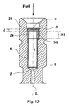
- the moving part 3, as it is in FIG. 11 is a flat plate, which as a single movable part 3 in the embodiment according to FIG. 12 Use finds.
- the length of the flat plate is preferably to be dimensioned so that it is slightly smaller than the inner diameter of the side wall 2a of the fixed part 2, so that on the one hand a good guidance of the plate within the fixed part 2 is given, but on the other hand, no unnecessary Friction losses may occur, which would even have a negative impact on the function of the check valve.
- the flat plate In the region of the opening O of the bottom part 2b, the flat plate has a width which is preferably greater than the diameter of this opening O.
Abstract
Description
Die Erfindung betrifft einen Kraftstoffanschlussstutzen mit einem darin angeordneten Kraftstofffilter nach dem Oberbegriff von Patentanspruch 1.The invention relates to a fuel connection with a fuel filter arranged therein according to the preamble of
Solche gattungsgemäßen Kraftstoffanschlussstutzen, die im Übrigen sowohl für flüssige als auch für gasförmige Kraftstoffe geeignet sind, sind seit langem im Einsatz, meist zusammen mit Einspritzventilen. Sie finden insbesondere bei Kraftfahrzeugen mit Einspritzventilen Anwendung, vorzugsweise bei solchen für Benzineinspritzung.Such generic fuel connection pieces, which are otherwise suitable for both liquid and gaseous fuels, have long been in use, usually together with injectors. They are used in particular in motor vehicles with injection valves application, preferably in those for gasoline injection.
Im Laufe der Zeit hat sich nun gezeigt, dass in Fällen, in denen (beispielsweise im Rahmen von Wartungsarbeiten in Autowerkstätten) bei abgeschaltetem Motor ein Einspritzventil von seiner Kraftstoffversorgung (dies kann beispielsweise ein so genanntes Rail sein) getrennt ist, unter bestimmten Umständen flüssiger und/oder gasförmiger Kraftstoff aus dem Kraftstoffanschlussstutzen austritt. Dieser Kraftstoffaustritt kann bei mit Benzin betriebenen Fahrzeugen insbesondere dann auftreten, wenn jemand seitlich gegen das (ausgebaute) Einspritzventil klopft oder wenn das Einspritzventil in einem noch sehr heißen Motor (z. B. Temperatur größer als 99° C) eingebaut ist. Ein solcher Vorgang ist nicht nur unangenehm, weil Kraftstoffe in der Regel unangenehme Gerüche verbreiten, sondern er ist auch für die Umwelt schädlich, weil diese dadurch verschmutzt wird. Weiterhin sind auch Personen in der unmittelbaren Umgebung eines solchen mit einem Einspritzventil verbundenen Kraftstoffanschlussstutzens dadurch gefährdet, dass sie von dem austretenden Kraftstoff durch Hautkontakt (zum Beispiel mittels Kraftstoffspritzer) oder durch Einatmen verletzt werden können, im Extremfall mit Todesfolge.Over time, it has now been shown that in cases where (for example in the context of maintenance work in garages) with the engine off, an injector is separated from its fuel supply (this may be a so-called rail) under certain circumstances more fluid and / or gaseous fuel leaking from the fuel connection. This fuel leakage can occur in gasoline-powered vehicles, in particular, when someone laterally knocked against the (removed) injection valve or when the injector is installed in a still very hot engine (eg temperature greater than 99 ° C). Such a process is not only unpleasant, because fuels generally spread unpleasant odors, but it is also harmful to the environment, because this is polluted by it. Furthermore, persons in the immediate vicinity of such connected to an injection valve fuel connection are at risk that they can be injured by the exiting fuel by skin contact (for example by means of fuel splash) or by inhalation, in extreme cases with death.
Aufgabe der vorliegenden Erfindung ist es deshalb, eine Anordnung zu schaffen, bei der das vorgenannte Austreten von Kraftstoff unterbunden ist.Object of the present invention is therefore to provide an arrangement in which the aforementioned leakage of fuel is prevented.
Diese Aufgabe wird bei einem gattungsgemäßen Kraftstoffanschlussstutzen mit den Mitteln des kennzeichnenden Teils von Patentanspruch 1 gelöst. Vorteilhafte Aus- und Weiterbildungen sind in Unteransprüchen gekennzeichnet.This object is achieved in a generic fuel connection with the means of the characterizing part of
Die Erfindung wird nachstehend anhand der Zeichnung näher erläutert. Dabei zeigen:
- Die
Figuren 12 zwei voneinander leicht verschiedene Ausführungsformen herkömmlicher Kraftstoffanschlussstutzen mit einem darin angeordneten Kraftstofffilter, teilweise im Schnitt, - die
Figur 3Figuren 12 , - die
Figuren 45 ,8 ,10 und12 verschiedene Ausführungsformen der vorliegenden Erfindung, wobei dieFigur 8 kein vollständiges Rückschlagventil zeigt, und - die
Figuren 6, 7 ,9 und 11 Einzelheiten der Ausführungsformen nach denFiguren 10 und12 .
- The
FIGS. 1 and2 two slightly different embodiments of conventional fuel connection pieces with a fuel filter arranged therein, partly in section, - the
FIG. 3 a section in plan view of the fuel port after theFIGS. 1 and2 . - the
FIGS. 4 .5 .8th .10 and12 various embodiments of the present invention, wherein theFIG. 8 does not show a complete check valve, and - the
FIGS. 6, 7 .9 and 11 Details of the embodiments according to theFigures 10 and12 ,
Der Kraftstoffanschlussstutzen nach
Der feststehende Teil 2 ist becherartig ausgeführt mit einer Seitenwand 2a, die einerseits an der Innenwand des Kraftstoffanschlussstutzens anliegt und andererseits an der Außenwand des ringförmig ausgebildeten Abschnitts S1 des Kraftstofffilters, und mit einem Bodenteil 2b, das, in Richtung der Längsachse L betrachtet, stirnförmig vor dem ringförmig ausgebildeten Abschnitt S1 des Kraftstofffilters angeordnet ist. Das Bodenteil 2b weist eine vorzugsweise mittig angeordnete Öffnung O auf, die für den Durchtritt von Kraftstoff vorgesehen ist. Das Bodenteil 2b ist bei dieser Ausführungsform, wiederum in Richtung der Längsachse L betrachtet, unmittelbar vor dem ringförmig ausgebildeten Abschnitt S1 des Kraftstofffilters angeordnet.The
Als beweglicher Teil 3 dient bei der Ausführungsform nach der
Im Normalbetrieb des Kraftstoffanschlussstutzens fließt der Kraftstoff in der durch den Pfeil "Fuel" angezeigten Richtung (auch in den restlichen Figuren der Zeichnung deutet der Pfeil "Fuel" die tatsächliche, oder aber auch die vom Kraftstoff her "erwünschte", Fließrichtung des Kraftstoffs an). Dabei drückt er die Kugel gegen das Abstandselement 4.In normal operation of the fuel connection nozzle, the fuel flows in the direction indicated by the arrow "Fuel" (also in the remaining figures of the drawing, the arrow "Fuel" indicates the actual, or also the fuel "desired", direction of flow of the fuel) , He pushes the ball against the spacer. 4
Wenn nun aus irgendwelchen Gründen außerhalb des Kraftstoffanschlussstutzens samt daran angeschlossenem Einspritzventil der Druck vor dem Kraftstofffilter niedriger ist oder wird als im Einspritzventil, versucht, wie bereits aufgetreten und eingangs beschrieben, Kraftstoff durch den Kraftstoffanschlussstutzen hindurch in Richtung auf die nicht mehr angeschlossene Kraftstoffversorgung (beispielsweise ein Rail) zu entweichen. Dabei nimmt der Kraftstoff das bewegliche Teil 3, zum Beispiel die Kugel, mit und drückt sie gegen die Öffnung O des Bodenteils 2b und verschließt diese. Somit kann keinerlei Kraftstoff austreten. Die Position des Abstandselements 4 bezüglich der Öffnung O bestimmt die Ansprechzeit des Rückschlagventils.If now for any reason outside of the fuel connector and its connected Injector, the pressure upstream of the fuel filter is lower than or is in the injection valve, trying, as already occurred and described above, fuel through the fuel port in the direction of the no longer connected fuel supply (for example, a rail) to escape. In this case, the fuel takes the
Der Gegenstand der Ausführungsform nach der
Funktionell unterscheiden sich die Gegenstände der
Beide Ausführungsformen könnten auch anstelle einer Kugel als bewegliches Teil 3 ein Zylinderteil mit nach außen hin abstehenden Stegen 3a aufweisen. Ein solches Zylinderteil ist in
Die Ausführungsformen nach den
Der Gegenstand von
Das bewegliche Teil 3 nach
Die Funktion des Gegenstandes der
Das bewegliche Teil 3, wie es in
Anzumerken ist noch, dass in der Zeichnung die Position dieses Plättchens in der Ausführungsform nach
Claims (18)
wobei der Kraftstofffilter an seinem einen Ende einen ringförmig ausgebildeten Abschnitt (S1) aufweist,
wobei der Kraftstofffilter an seinem anderen Ende eine Bodenplatte (P) aufweist,
wobei zwischen dem ringförmig ausgebildeten Abschnitt (S1) und der Bodenplatte (P) eine Mehrzahl von Rippen (R) angeordnet ist,
wobei zwischen dem ringförmig ausgebildeten Abschnitt (S1) und der Bodenplatte (P) weiterhin ein Filtermaterial (F) hohlzylinderartig oder sacklochartig angeordnet ist derart dass der Abstand des Filtermaterials (F)zur Längsachse (L) geringer ist als der Abstand der Rippen (R) zur Längsachse (L), und
wobei das Filtermaterial (F) entweder mit sich allein oder zusammen mit der Bodenplatte (P) ein Sackloch bildet,
dadurch gekennzeichnet, dass
der Kraftstofffilter weiterhin ein Rückschlagventil aufweist.A fuel port (1) having a longitudinal axis (L) with a fuel filter disposed therein along its longitudinal axis (L),
wherein the fuel filter has an annular portion (S1) at one end thereof,
the fuel filter having at its other end a bottom plate (P),
wherein between the annular portion (S1) and the bottom plate (P) a plurality of ribs (R) is arranged,
wherein between the annular portion (S1) and the bottom plate (P) further a filter material (F) is arranged like a hollow cylinder or blind hole such that the distance of the filter material (F) to the longitudinal axis (L) is less than the distance of the ribs (R) to the longitudinal axis (L), and
wherein the filter material (F) forms a blind hole either alone or together with the bottom plate (P),
characterized in that
the fuel filter further comprises a check valve.
dadurch gekennzeichnet, dass
der ringförmig ausgebildete Abschnitt (S1) einen metallischen Ring (R) aufweist.Fuel connection piece according to claim 1,
characterized in that
the annular portion (S1) has a metallic ring (R).
dadurch gekennzeichnet, dass
das Rückschlagventil aus einem feststehenden Teil (2) und wenigstens einem beweglichen Teil (3) gebildet ist.Fuel connection piece according to claim 1 or 2,
characterized in that
the check valve is formed from a fixed part (2) and at least one movable part (3).
dadurch gekennzeichnet, dass
der feststehende Teil (2) becherartig mit einer Seitenwand (2a) und mit einem Bodenteil (2b) ausgeführt ist derart, dass die Seitenwand (2a) um den ringförmig ausgebildeten Abschnitt (S1) herum angeordnet ist, dass das Bodenteil (2b), in Richtung der Längsachse (L) betrachtet, stirnförmig vor dem ringförmig ausgebildeten Abschnitt (S1) angeordnet ist, und dass das Bodenteil (2b) eine insbesondere mittig angeordnete Öffnung (O) aufweist.Fuel connection piece according to claim 3,
characterized in that
the fixed part (2) is cup-shaped with a side wall (2a) and with a bottom part (2b) is designed such that the side wall (2a) is arranged around the ring-shaped section (S1) such that the bottom part (2b), viewed in the direction of the longitudinal axis (L), is arranged frontally in front of the ring-shaped section (S1), and in that the bottom part (FIG. 2b) has a particular centrally disposed opening (O).
dadurch gekennzeichnet, dass
das Bodenteil (2b), in Richtung der Längsachse (L) betrachtet, unmittelbar vor dem ringförmig ausgebildeten Abschnitt (S1) angeordnet ist.Fuel connection piece according to claim 4,
characterized in that
the bottom part (2b), viewed in the direction of the longitudinal axis (L), is arranged directly in front of the annular section (S1).
dadurch gekennzeichnet, dass
der feststehende Teil (2) als Scheibe (2c) mit einer mittig angebrachten Öffnung (O), in Richtung der Längsachse (L) betrachtet, stirnförmig und unmittelbar vor dem ringförmig ausgebildeten Abschnitt (S1) angeordnet ist.Fuel connection piece according to claim 3,
characterized in that
the stationary part (2) is arranged as a disc (2c) with a centrally mounted opening (O), viewed in the direction of the longitudinal axis (L), in the form of an end face and immediately in front of the annular section (S1).
dadurch gekennzeichnet, dass
das Rückschlagventil weiterhin ein Abstandselement (4) aufweist, dessen Position eine Ruheposition des beweglichen Teils (3) definiert.Fuel connection piece according to one of claims 3 to 6,
characterized in that
the check valve further comprises a spacer element (4) whose position defines a rest position of the movable part (3).
dadurch gekennzeichnet, dass
das beweglich Teil (3) und das Abstandselement (4) innerhalb eines durch das Filtermaterial (F) und den ringförmig ausgebildeten Abschnitt (S1) gebildeten Raums derart angeordnet sind, dass sich das bewegliche Teil (3) stets in einem Bereich vor dem dem ringförmig ausgebildeten Abschnitt (S1) zugewandten Ende des Abstandselements (4) befindet.Fuel connection piece according to claim 7,
characterized in that
the movable part (3) and the spacer (4) are arranged within a space formed by the filter material (F) and the annular portion (S1) such that the movable part (3) always faces in an area in front of the annular one formed portion (S1) facing the end of the spacer element (4) is located.
dadurch gekennzeichnet, dass
das bewegliche Teil (3) eine Kugel ist.Fuel connection piece according to claim 8,
characterized in that
the movable part (3) is a ball.
dadurch gekennzeichnet, dass
das bewegliche Teil (3) ein Zylinderteil mit entlang der Zylinderlängswand angeordneten, nach außen abstehenden Stegen (3a) ist.Fuel connection piece according to claim 8,
characterized in that
the movable part (3) is a cylinder part with along the cylinder longitudinal wall arranged, outwardly projecting webs (3a).
dadurch gekennzeichnet, dass
das Zylinderteil ein einseitig geschlossener Hohlzylinder ist.Fuel connection piece according to claim 10,
characterized in that
the cylinder part is a hollow cylinder closed on one side.
dadurch gekennzeichnet, dass
das Bodenteil (2b) in einem gegebenen Abstand (d) vor dem ringförmig ausgebildeten Abschnitt (S1) angeordnet ist.Fuel connection piece according to claim 4,
characterized in that
the bottom part (2b) is arranged at a given distance (d) in front of the annular section (S1).
dadurch gekennzeichnet, dass
als bewegliches Teil (3) ein Teil vorgesehen ist, welches aus einem kreuzförmig ausgebildeten Teil (3i), einer Scheibe (3j) und einer zwischen dem kreuzförmig ausgebildeten Teil (3i) und der Scheibe (3j) angeordneten Verbindungsstab (3k) gebildet ist.Fuel connection piece according to claim 12,
characterized in that
as a movable part (3) a part is provided, which is formed of a cross-shaped part (3i), a disc (3j) and between the cross-shaped part (3i) and the disc (3j) arranged connecting rod (3k).
dadurch gekennzeichnet, dass
das bewegliche Teil (3) ein- oder mehrstückig ausgeführt ist.Fuel connection piece according to claim 13,
characterized in that
the movable part (3) is made in one or more pieces.
dadurch gekennzeichnet, dass
das bewegliche Teil (3) anstelle des kreuzförmig ausgebildeten Teils (3i) lediglich ein einzelnes, stabförmig ausgebildetes Teil enthält.Fuel connection piece according to claim 13 or 14,
characterized in that
the movable part (3) instead of the cross-shaped part (3i) contains only a single, rod-shaped part.
dadurch gekennzeichnet, dass
jeder einzelne der das kreuzförmig oder stabförmig ausgebildete Teil (3i) bildenden Stäbe länger als der Durchmesser der Öffnung (0) des Bodenteils (2b) ist.Fuel connection piece according to one of claims 13 to 15,
characterized in that
each of the cross-shaped or rod-shaped part (3i) forming rods is longer than the diameter of the opening (0) of the bottom part (2b).
dadurch gekennzeichnet, dass
der Durchmesser der Scheibe (3j) größer als der Durchmesser der Öffnung (O) des Bodenteils (2b) ist.Fuel connection piece according to one of claims 13 to 16,
characterized in that
the diameter of the disc (3j) is greater than the diameter of the opening (O) of the bottom part (2b).
dadurch gekennzeichnet, dass
das bewegliche Teil (3) ein flaches, längliches Plättchen ist, dessen Länge gleich dem Innendurchmesser der Seitenwand (2a) ist abzüglich eines Maßes, das notwendig ist, um eine ansonsten bei Bewegung des Plättchens entlang der Längsachse (L) des Kraftstoffanschlussstutzens zwischen der Seitenwand (2a) und den Enden das Plättchens auftretende Reibung zu minimieren, und dessen Breite im Bereich der Öffnung (O) des Bodenteils (2b) größer ist als der Durchmesser dieser Öffnung (O).Fuel connection piece according to claim 12,
characterized in that
the movable part (3) is a flat, elongate plate whose length is equal to the inner diameter of the side wall (2a) less a measure necessary to otherwise move the plate along the longitudinal axis (L) of the fuel connection between the side wall (2a) and minimize the friction occurring at the ends of the plate, and whose width in the region of the opening (O) of the bottom part (2b) is greater than the diameter of this opening (O).
Priority Applications (1)
| Application Number | Priority Date | Filing Date | Title |
|---|---|---|---|
| EP07425551A EP2034173A1 (en) | 2007-09-07 | 2007-09-07 | Fuel fitting with fuel filter |
Applications Claiming Priority (1)
| Application Number | Priority Date | Filing Date | Title |
|---|---|---|---|
| EP07425551A EP2034173A1 (en) | 2007-09-07 | 2007-09-07 | Fuel fitting with fuel filter |
Publications (1)
| Publication Number | Publication Date |
|---|---|
| EP2034173A1 true EP2034173A1 (en) | 2009-03-11 |
Family
ID=38925622
Family Applications (1)
| Application Number | Title | Priority Date | Filing Date |
|---|---|---|---|
| EP07425551A Withdrawn EP2034173A1 (en) | 2007-09-07 | 2007-09-07 | Fuel fitting with fuel filter |
Country Status (1)
| Country | Link |
|---|---|
| EP (1) | EP2034173A1 (en) |
Citations (4)
| Publication number | Priority date | Publication date | Assignee | Title |
|---|---|---|---|---|
| EP0106183A1 (en) * | 1982-10-13 | 1984-04-25 | Robert Bosch Gmbh | Fuel injection nozzle for internal-combustion engines |
| US4608166A (en) * | 1985-04-01 | 1986-08-26 | Filtertek, Inc. | Press fit filter |
| WO2005113976A1 (en) * | 2004-05-18 | 2005-12-01 | Robert Bosch Gmbh | Fuel-injection system |
| FR2874973A1 (en) * | 2004-09-09 | 2006-03-10 | Renault Sas | Fuel supply system for internal combustion engine, has injector connected to common rail through supply conduit that includes tubular unit for filtering fuel and attenuating pressure waves in conduit |
-
2007
- 2007-09-07 EP EP07425551A patent/EP2034173A1/en not_active Withdrawn
Patent Citations (4)
| Publication number | Priority date | Publication date | Assignee | Title |
|---|---|---|---|---|
| EP0106183A1 (en) * | 1982-10-13 | 1984-04-25 | Robert Bosch Gmbh | Fuel injection nozzle for internal-combustion engines |
| US4608166A (en) * | 1985-04-01 | 1986-08-26 | Filtertek, Inc. | Press fit filter |
| WO2005113976A1 (en) * | 2004-05-18 | 2005-12-01 | Robert Bosch Gmbh | Fuel-injection system |
| FR2874973A1 (en) * | 2004-09-09 | 2006-03-10 | Renault Sas | Fuel supply system for internal combustion engine, has injector connected to common rail through supply conduit that includes tubular unit for filtering fuel and attenuating pressure waves in conduit |
Similar Documents
| Publication | Publication Date | Title |
|---|---|---|
| DE4341545A1 (en) | Fuel injection device for internal combustion engines | |
| WO2018001542A1 (en) | Tank valve | |
| EP3152434B1 (en) | High-pressure fuel pump comprising a discharge valve with a valve ball and a valve body | |
| DE102008041165A1 (en) | Injection valve member | |
| EP1915525B1 (en) | Divided double seat injection valve member | |
| DE102014103918A1 (en) | fuel Injector | |
| DE10131640A1 (en) | Fuel injector with injection course shaping through switchable throttle elements | |
| WO2001051805A2 (en) | Injector | |
| DE69921242T2 (en) | Fuel injection valve | |
| EP3055551B1 (en) | Control valve | |
| AT502512B1 (en) | gas metering valve | |
| EP1043497B1 (en) | Control valve | |
| WO2022063733A1 (en) | Electromagnetic valve, in particular for motor vehicles | |
| EP2034173A1 (en) | Fuel fitting with fuel filter | |
| DE102013220913A1 (en) | Valve | |
| DE102007006946A1 (en) | Injector for injecting fuel into combustion chambers of internal combustion engines | |
| DE102017218527A1 (en) | Injector for dosing liquid and gaseous fuel | |
| DE102014205444A1 (en) | Gas injector with two sealing areas | |
| DE102012211156A1 (en) | Fuel injector for combustion chamber of internal combustion engine, has nozzle needle end region that is extended towards longitudinal axis of guide ribs, and flow gap that is formed between guide ribs and end section | |
| DE60318526T2 (en) | FUEL INJECTION DEVICE FOR A COMBUSTION ENGINE WITH HYDRAULIC PENETRATING | |
| EP0698182A1 (en) | Injection nozzle for internal combustion engines | |
| DE10121340A1 (en) | Common rail injector for internal combustion engine fuel injection system has casing and intermediate plate bounding control chamber implemented in one piece with inlet and outlet choke | |
| DE10106892A1 (en) | Pilot operated 2/2-way seat valve | |
| DE102020206899A1 (en) | Gas metering valve | |
| EP3237748A1 (en) | Pressure regulator for a high-pressure ramp of a fuel injection system |
Legal Events
| Date | Code | Title | Description |
|---|---|---|---|
| PUAI | Public reference made under article 153(3) epc to a published international application that has entered the european phase |
Free format text: ORIGINAL CODE: 0009012 |
|
| AK | Designated contracting states |
Kind code of ref document: A1 Designated state(s): AT BE BG CH CY CZ DE DK EE ES FI FR GB GR HU IE IS IT LI LT LU LV MC MT NL PL PT RO SE SI SK TR |
|
| AX | Request for extension of the european patent |
Extension state: AL BA HR MK RS |
|
| AKX | Designation fees paid | ||
| REG | Reference to a national code |
Ref country code: DE Ref legal event code: 8566 |
|
| STAA | Information on the status of an ep patent application or granted ep patent |
Free format text: STATUS: THE APPLICATION IS DEEMED TO BE WITHDRAWN |
|
| 18D | Application deemed to be withdrawn |
Effective date: 20090912 |