EP2033872A2 - Apparatus supporting mechanism, sheet feeding apparatus and image forming apparatus - Google Patents
Apparatus supporting mechanism, sheet feeding apparatus and image forming apparatus Download PDFInfo
- Publication number
- EP2033872A2 EP2033872A2 EP08163691A EP08163691A EP2033872A2 EP 2033872 A2 EP2033872 A2 EP 2033872A2 EP 08163691 A EP08163691 A EP 08163691A EP 08163691 A EP08163691 A EP 08163691A EP 2033872 A2 EP2033872 A2 EP 2033872A2
- Authority
- EP
- European Patent Office
- Prior art keywords
- supporting
- sheet
- disposed
- image forming
- supporting mechanism
- Prior art date
- Legal status (The legal status is an assumption and is not a legal conclusion. Google has not performed a legal analysis and makes no representation as to the accuracy of the status listed.)
- Granted
Links
- 230000007246 mechanism Effects 0.000 title claims abstract description 43
- 238000009434 installation Methods 0.000 claims abstract description 28
- 238000000034 method Methods 0.000 description 3
- 230000001965 increasing effect Effects 0.000 description 2
- 230000008569 process Effects 0.000 description 2
- 238000000926 separation method Methods 0.000 description 2
- 230000015572 biosynthetic process Effects 0.000 description 1
- 230000006835 compression Effects 0.000 description 1
- 238000007906 compression Methods 0.000 description 1
- 230000000593 degrading effect Effects 0.000 description 1
- 230000002708 enhancing effect Effects 0.000 description 1
- 230000005484 gravity Effects 0.000 description 1
- 238000012986 modification Methods 0.000 description 1
- 230000004048 modification Effects 0.000 description 1
- 230000004044 response Effects 0.000 description 1
Images


Classifications
-
- G—PHYSICS
- G03—PHOTOGRAPHY; CINEMATOGRAPHY; ANALOGOUS TECHNIQUES USING WAVES OTHER THAN OPTICAL WAVES; ELECTROGRAPHY; HOLOGRAPHY
- G03G—ELECTROGRAPHY; ELECTROPHOTOGRAPHY; MAGNETOGRAPHY
- G03G15/00—Apparatus for electrographic processes using a charge pattern
- G03G15/65—Apparatus which relate to the handling of copy material
- G03G15/6502—Supplying of sheet copy material; Cassettes therefor
-
- B—PERFORMING OPERATIONS; TRANSPORTING
- B62—LAND VEHICLES FOR TRAVELLING OTHERWISE THAN ON RAILS
- B62B—HAND-PROPELLED VEHICLES, e.g. HAND CARTS OR PERAMBULATORS; SLEDGES
- B62B5/00—Accessories or details specially adapted for hand carts
- B62B5/04—Braking mechanisms; Locking devices against movement
- B62B5/049—Braking mechanisms; Locking devices against movement locking against movement by contacting the floor or a wall
-
- G—PHYSICS
- G03—PHOTOGRAPHY; CINEMATOGRAPHY; ANALOGOUS TECHNIQUES USING WAVES OTHER THAN OPTICAL WAVES; ELECTROGRAPHY; HOLOGRAPHY
- G03G—ELECTROGRAPHY; ELECTROPHOTOGRAPHY; MAGNETOGRAPHY
- G03G21/00—Arrangements not provided for by groups G03G13/00 - G03G19/00, e.g. cleaning, elimination of residual charge
- G03G21/16—Mechanical means for facilitating the maintenance of the apparatus, e.g. modular arrangements
- G03G21/1604—Arrangement or disposition of the entire apparatus
- G03G21/1623—Means to access the interior of the apparatus
- G03G21/1638—Means to access the interior of the apparatus directed to paper handling or jam treatment
-
- B—PERFORMING OPERATIONS; TRANSPORTING
- B65—CONVEYING; PACKING; STORING; HANDLING THIN OR FILAMENTARY MATERIAL
- B65H—HANDLING THIN OR FILAMENTARY MATERIAL, e.g. SHEETS, WEBS, CABLES
- B65H2601/00—Problem to be solved or advantage achieved
- B65H2601/10—Ensuring correct operation
- B65H2601/11—Clearing faulty handling, e.g. jams
-
- G—PHYSICS
- G03—PHOTOGRAPHY; CINEMATOGRAPHY; ANALOGOUS TECHNIQUES USING WAVES OTHER THAN OPTICAL WAVES; ELECTROGRAPHY; HOLOGRAPHY
- G03G—ELECTROGRAPHY; ELECTROPHOTOGRAPHY; MAGNETOGRAPHY
- G03G2215/00—Apparatus for electrophotographic processes
- G03G2215/00362—Apparatus for electrophotographic processes relating to the copy medium handling
- G03G2215/00535—Stable handling of copy medium
- G03G2215/00544—Openable part of feed path
-
- G—PHYSICS
- G03—PHOTOGRAPHY; CINEMATOGRAPHY; ANALOGOUS TECHNIQUES USING WAVES OTHER THAN OPTICAL WAVES; ELECTROGRAPHY; HOLOGRAPHY
- G03G—ELECTROGRAPHY; ELECTROPHOTOGRAPHY; MAGNETOGRAPHY
- G03G2221/00—Processes not provided for by group G03G2215/00, e.g. cleaning or residual charge elimination
- G03G2221/16—Mechanical means for facilitating the maintenance of the apparatus, e.g. modular arrangements and complete machine concepts
- G03G2221/1672—Paper handling
- G03G2221/1675—Paper handling jam treatment
-
- G—PHYSICS
- G03—PHOTOGRAPHY; CINEMATOGRAPHY; ANALOGOUS TECHNIQUES USING WAVES OTHER THAN OPTICAL WAVES; ELECTROGRAPHY; HOLOGRAPHY
- G03G—ELECTROGRAPHY; ELECTROPHOTOGRAPHY; MAGNETOGRAPHY
- G03G2221/00—Processes not provided for by group G03G2215/00, e.g. cleaning or residual charge elimination
- G03G2221/16—Mechanical means for facilitating the maintenance of the apparatus, e.g. modular arrangements and complete machine concepts
- G03G2221/1678—Frame structures
- G03G2221/1684—Frame structures using extractable subframes, e.g. on rails or hinges
Definitions
- the present invention relates to an apparatus supporting mechanism which is disposed at a bottom of an apparatus movable on an installation plane for supporting the apparatus when the apparatus is installed. Furthermore, the present invention relates to a movable sheet feeding apparatus provided with the apparatus supporting mechanism and an image forming apparatus provided with the sheet feeding apparatus.
- a sheet feeding apparatus for supplying a sheet to the image forming apparatus tends to gradually increase a sheet stacking capacity.
- Such a sheet feeding apparatus of a large capacity is used in a state in which the image forming apparatus is mounted thereon, and therefore, a weight and an outer dimension are liable to become larger in use.
- Sheet feeding apparatus having a large capacity is normally provided with casters including a pivotal fixing portion rotatably having wheels at the bottom thereof for the purpose of easy movement or installation.
- the sheet feeding apparatus mostly includes a locking mechanism for locking the rotation of the wheels in the caster, or an adjusting mechanism with respect to an apparatus installation plane at the bottom of the apparatus, in order to prevent any movement of the apparatus in the case where an external force is exerted on the apparatus by an operator.
- the adjusting mechanism may have to project outward from the outline of the apparatus in order to secure stability.
- the apparatus passes, for example, a step during its movement, there may occur an inconvenience that the adjusting mechanism projecting outward of the apparatus collides against the step.
- package material for shipping the apparatus requires a larger size because of the outward projection of the adjusting mechanism, thereby increasing cost and reducing distribution efficiency.
- a method for solving the above-described problems is exemplified by an apparatus to which an adjusting mechanism is detachably attached, or by an apparatus on or to which an adjusting mechanism is disposed in such a manner as to freely slide outward or be fixed (Japanese Patent Application Laid-open No. 10-236670 ).
- the present invention provides an apparatus supporting mechanism capable of enhancing operability, a sheet feeding apparatus provided with the same and an image forming apparatus.
- the present invention in its first aspect provides an exposure apparatus as specified in claims 1 to 4.
- the present invention in its second aspect provides an exposure apparatus as specified in claim 5.
- the present invention in its third aspect provides an exposure apparatus as specified in claims 6 to 7.
- FIG. 1 is a perspective view illustrating an apparatus supporting mechanism
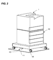
- FIG. 2 is a perspective view illustrating an apparatus as a whole when a supporting member is located at a housed position
- FIG. 3 is a top view illustrating the apparatus supporting mechanism when the supporting member is located at the housed position
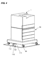
- FIG. 4 is a perspective view illustrating the apparatus as a whole when the supporting member is located at a projecting position
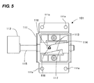
- FIG. 5 is a top view illustrating the apparatus supporting mechanism when the supporting member is located at the projecting position.
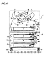
- FIG. 6 is a front view illustrating the entire configuration of an image forming apparatus.
- An apparatus supporting mechanism in embodiments according to the present invention is exemplified by disposing it in a sheet feeding apparatus and an image forming apparatus.
- FIG. 6 illustrates the schematic configuration of a laser beam printer as one example of the image forming apparatus in the present embodiment.
- a printer body 1 is disposed above whereas a feeding deck 50 serving as a sheet feeding apparatus to be optionally fixed is disposed below.
- the printer body 1 is provided with an image forming portion 1A which includes a process cartridge 7 having a photosensitive drum 7a, a charger 7b, a developing sleeve 7c and a cleaner 7d, a laser scanner 8 and a transfer roller 9.
- a process cartridge 7 having a photosensitive drum 7a, a charger 7b, a developing sleeve 7c and a cleaner 7d, a laser scanner 8 and a transfer roller 9.
- the laser scanner 8 Upon start of an image forming operation, in the image forming portion 1A, the laser scanner 8 illuminates the photosensitive drum 7a with a laser beam in response to an image signal, and then, an electrostatic latent image is formed on the photosensitive drum 7a.
- the electrostatic latent image is developed with a toner contained in the process cartridge 7, thereby forming a toner image on the photosensitive drum 7a.
- a sheet S is fed from a sheet cassette 2 disposed in the printer body 1 via a feed roller 3 and a pair of separation rollers 4 or from another sheet cassette 52 (52a, 52b or 52c) disposed in the feeding deck 50.
- the sheet S is conveyed to a transfer portion including the photosensitive drum 7a and the transfer roller 9 in synchronism with toner image formation on the photosensitive drum 7a via conveying rollers 5 and a pair of registration rollers 6.
- the toner image is transferred onto the sheet S.
- the sheet S having the toner image transferred thereonto is conveyed to a fixing portion 10, in which the sheet S is pressurized and heated, to be thus fixed with the toner image. Thereafter, the sheet S is discharged onto a discharge portion 12 disposed at an upper portion in the apparatus via discharge rollers 11.
- the feeding deck 50 serving as the sheet feeding apparatus is provided with the sheet cassettes 52 consisting of a plurality of sheet stacks (three in the present embodiment) and feed rollers 53 (53a, 53b and 53c) serving as sheet feeding members for feeding the sheets S stacked in the sheet cassettes, respectively.
- the three sheet cassettes 52 are configured to freely stack and feed sheets of various sizes and basis weights.
- the feeding deck 50 also serves as a mount table for the printer body 1, and further, has casters 59 at four points at the lower surface of the apparatus body in consideration of the movement in a state in which the printer body 1 is placed on the feeding deck 50.
- the feeding deck 50 is adapted to feed the sheet S via the feed roller 53 from the sheet cassette 52 upon receipt of a feed signal from the printer body 1.
- the sheets S fed via the feed roller 53 are separated one by one by a pair of separation rollers 54 (54a, 54b and 54c), and thereafter, are fed into the printer body 1 via conveyor rollers 56 (56a, 56b and 56c).
- Casters 59 are attached to the feeding stack at the four corners at the bottom of the feeding deck 50, as illustrated in FIGS. 4 and 5 .
- the casters 59 are attached in consideration of the movement in the state in which the printer body 1 is placed on the feeding deck 50, and therefore, have a satisfactory load resistance.
- apparatus supporting mechanism 101 supports the apparatus in order to prevent the apparatus from falling down.
- the apparatus supporting mechanism 101 is disposed at the bottom surface of the feeding deck 50, and has a configuration described below.
- the apparatus supporting mechanism 101 includes a fixing member 111, a guiding member 114, a connecting member 115 and a supporting member 112.
- the fixing member 111 is formed into the shape of a box, and is fixingly screwed at the bottom surface of the feeding deck 50 via screw holes 111a bored at a flange in an upper portion. Inside of the fixing member 111 is contained the guiding member 114.
- the connecting member 115 slides with respect to the fixing member 111 in such a manner as to project therefrom or be housed therein.
- To an end of the connecting member 115 is fixed the supporting member 112 which is grounded onto the apparatus installation surface when the feeding deck 50 is inclined so as to support the feeding deck 50 and/or printer body.
- the supporting member 112 is formed into the shape of a cuboid having one long side, as illustrated in FIG. 1 .
- the supporting member 112 can be displaced between a first position, at which it is grounded onto the installation plane of the feeding deck 50 by a displacing mechanism, and a second position, at which it is separated from the installation plane.
- the displacing mechanism will be descried.
- the guiding member 114 having guide grooves 113 is housed inside of the fixing member 111.
- the supporting member 112 is fixed to the end of one side of the shaft-like connecting member 115, and therefore, is fixed in such a manner as to be rotatable in association with the connecting member.
- the connecting member 115 is fixed to the fixing member 111, and further, is fixed in a manner as to project from the fixing member 111 or be housed therein. Accordingly, the supporting member 112 also projects outward of the installation region of the feeding deck 50 or is retractable into the installation region of the feeding deck 50.
- the connecting member 115 has a pin 116 to be guided serving as a portion to be guided projecting therefrom, and thus, the pin 116 to be guided is fitted in the guide groove 113 formed at the guiding member 114.
- the guide groove 113 is formed in the shape of a helix the axis of which lies in the direction in which the connecting member 115 projects and is housed.
- the pin 116 to be guided is adapted to be rotated along the helical guide groove 113 when the guiding member 114 is made to project and be housed.
- a housing spring 117 serving as a biasing member comprising a compression spring extending through the connecting member 115 is interposed between the pin 116 to be guided and the fixing member 111.
- the connecting member 115 is biased at all times toward the housing direction by the housing spring 117.
- a locking portion 118 for locking the pin 116 to be guided is formed at the guide groove 113 so as to maintain the projecting state at a position from which the connecting member 115 projects.
- the supporting member 112 fixed to the end of the connecting member 115 can be displaced between the first position, at which the supporting member 112 is grounded with respect to the installation plane of the feeding deck 50, and the second position, at which the supporting member 112 is separated from the installation plane, as described above.
- the supporting member 112 becomes horizontal in a longitudinal direction, to be thus separated from the ground or the installation plane of the feeding deck 50 in a state in which the connecting member 115 is housed (at the second position), and then, is retracted in the installation plane of the feeding deck 50, as illustrated in FIG. 2 .
- the connecting member 115 is maintained in a state drawn by the housing spring 117, and then, the supporting member 112 is fixed in the housed state, as illustrated in FIG. 3 .
- the pin 116 to be guided is rotated by 1/4 under the guidance of the spiral guide groove 113, as described above.
- the supporting member 112 projects outward of an installation area of the feeding deck 50, and further, is grounded to the installation plane while the longitudinal direction thereof is oriented vertically (i.e., the first position).
- the pin 116 to be guided is fitted into the locking portion 118 of the guide groove 113, as illustrated in FIG. 5 , and thus, the supporting member 112 is fixed in this state.
- the supporting member 112 When the supporting member 112 is displaced to the first position, it may not be completely grounded onto the apparatus installation plane. When the apparatus is inclined, the supporting member 112 is adapted to prevent the apparatus from falling over. Therefore, the supporting member 112 may be normally located in the proximity of the apparatus installation plane, but the supporting member 112 maybe grounded to support the apparatus when the apparatus is even slightly inclined.
- the first position of the supporting member 112 in the present embodiment includes not only the position at which the supporting member 112 is completely grounded but also a position at which the supporting member 112 is located adjacent the ground - i.e. in the proximity of the installation plane.
- the pin 116 to be guided is drawn while being rotated under the guidance of the spiral guide groove 113.
- the locking portion 118 is released from being locked to the pin 116 to be guided by slightly drawing the supporting member 112.
- the connecting member 115 is drawn by the tensile force of the housing spring 117, so that the supporting member 112 is retracted and housed at the housed position while being rotated.
- the operation for making the supporting member 112 project or be retracted (housed) in order to prevent the apparatus from falling down and the operation for grounding or separating the supporting member 112 to or from the apparatus installation plane can be implemented by a single operation.
- the apparatus supporting mechanism is disposed at the bottom of the sheet feeding apparatus in the above-described embodiment.
- the casters may be fixed to the bottom of the image forming apparatus in a movable manner, and then, the above-described apparatus supporting mechanism may be fixed to the bottom of the image forming apparatus directly.
- the above-described apparatus supporting mechanism need not be limited to the case where it is fixed to the bottom of the sheet feeding apparatus or the image forming apparatus, and is effective in the case where it is fixed to another movable apparatus to prevent the apparatus from falling over.
- An apparatus supporting mechanism which is disposed at a bottom of an apparatus movable on an installation plane and can support the apparatus when the apparatus is installed in order to achieve the above object, includes a fixing member fixed to the bottom of the apparatus; a connecting member disposed in the fixing member in such a manner as to freely project and be housed; a supporting member disposed in the connecting member and freely displaced between a first position, at which the supporting member is grounded or located proximate with respect to the installation plane of the apparatus, a second position, at which the supporting member is separate from the installation plane of the apparatus; and a displacing mechanism which displaces the supporting member to the first position when the connecting member projects while displaces the supporting member to the second position when the connecting member is housed.
- a sheet feeding apparatus in order to achieve the above object, includes a sheet stack disposed in the apparatus, to stack sheets thereon; a sheet feeding member which feeds the sheet from the sheet stack; and the apparatus supporting mechanism disposed at the bottom of the apparatus.
- An image forming apparatus in order to achieve the above object, includes the sheet feeding apparatus; and an image forming portion which forms an image on a sheet fed from the sheet feeding apparatus.
- An image forming apparatus in order to achieve the above object, includes an image forming portion which is disposed in the apparatus so as to form an image on a sheet; and the apparatus supporting mechanism disposed at the bottom of the apparatus.
Landscapes
- Engineering & Computer Science (AREA)
- Physics & Mathematics (AREA)
- General Physics & Mathematics (AREA)
- Chemical & Material Sciences (AREA)
- Combustion & Propulsion (AREA)
- Transportation (AREA)
- Mechanical Engineering (AREA)
- Electrophotography Configuration And Component (AREA)
- Sheets, Magazines, And Separation Thereof (AREA)
- Accessory Devices And Overall Control Thereof (AREA)
- Casings For Electric Apparatus (AREA)
Abstract
Description
- The present invention relates to an apparatus supporting mechanism which is disposed at a bottom of an apparatus movable on an installation plane for supporting the apparatus when the apparatus is installed. Furthermore, the present invention relates to a movable sheet feeding apparatus provided with the apparatus supporting mechanism and an image forming apparatus provided with the sheet feeding apparatus.
- The processing speed of image forming apparatuses such as printers or a copying machines has increased in recent years. A sheet feeding apparatus for supplying a sheet to the image forming apparatus tends to gradually increase a sheet stacking capacity. Such a sheet feeding apparatus of a large capacity is used in a state in which the image forming apparatus is mounted thereon, and therefore, a weight and an outer dimension are liable to become larger in use.
- Sheet feeding apparatus having a large capacity is normally provided with casters including a pivotal fixing portion rotatably having wheels at the bottom thereof for the purpose of easy movement or installation. Moreover, the sheet feeding apparatus mostly includes a locking mechanism for locking the rotation of the wheels in the caster, or an adjusting mechanism with respect to an apparatus installation plane at the bottom of the apparatus, in order to prevent any movement of the apparatus in the case where an external force is exerted on the apparatus by an operator.
- In the case of a heavy apparatus or an apparatus having a high center of gravity and having an adjusting mechanism with respect to the apparatus installation plane at the bottom of the apparatus, the adjusting mechanism may have to project outward from the outline of the apparatus in order to secure stability. In such a case, when the apparatus passes, for example, a step during its movement, there may occur an inconvenience that the adjusting mechanism projecting outward of the apparatus collides against the step. Also, package material for shipping the apparatus requires a larger size because of the outward projection of the adjusting mechanism, thereby increasing cost and reducing distribution efficiency.
- A method for solving the above-described problems is exemplified by an apparatus to which an adjusting mechanism is detachably attached, or by an apparatus on or to which an adjusting mechanism is disposed in such a manner as to freely slide outward or be fixed (Japanese Patent Application Laid-open No.
10-236670 - However, in the prior art provided with the adjusting mechanism detachably attached to an apparatus body, as described above, a person who installs the apparatus needs to install the apparatus on a floor by rotating adjuster screws fitted at several points many times, thereby degrading workability. Moreover, when the apparatus is moved without detaching an adjuster unintentionally in the case where the apparatus is moved again by the casters after the apparatus is installed, the adjuster possibly collides against a step or other obstacle.
- The present invention provides an apparatus supporting mechanism capable of enhancing operability, a sheet feeding apparatus provided with the same and an image forming apparatus.
- The present invention in its first aspect provides an exposure apparatus as specified in
claims 1 to 4. - The present invention in its second aspect provides an exposure apparatus as specified in claim 5.
- The present invention in its third aspect provides an exposure apparatus as specified in claims 6 to 7.
- Further features of the present invention will become apparent from the following description of exemplary embodiments (with reference to the attached drawings).
-
FIG. 1 is a perspective view illustrating an apparatus supporting mechanism; -
FIG. 2 is a perspective view illustrating an apparatus as a whole when a supporting member is located at a housed position; -
FIG. 3 is a top view illustrating the apparatus supporting mechanism when the supporting member is located at the housed position; -
FIG. 4 is a perspective view illustrating the apparatus as a whole when the supporting member is located at a projecting position; -
FIG. 5 is a top view illustrating the apparatus supporting mechanism when the supporting member is located at the projecting position; and -
FIG. 6 is a front view illustrating the entire configuration of an image forming apparatus. - An apparatus supporting mechanism in embodiments according to the present invention is exemplified by disposing it in a sheet feeding apparatus and an image forming apparatus.
- First of all, an image forming apparatus provided with an apparatus supporting mechanism will be described in reference to
FIG. 6 . Here,FIG. 6 illustrates the schematic configuration of a laser beam printer as one example of the image forming apparatus in the present embodiment. Aprinter body 1 is disposed above whereas afeeding deck 50 serving as a sheet feeding apparatus to be optionally fixed is disposed below. - The
printer body 1 is provided with animage forming portion 1A which includes aprocess cartridge 7 having aphotosensitive drum 7a, a charger 7b, a developing sleeve 7c and acleaner 7d, a laser scanner 8 and a transfer roller 9. - Upon start of an image forming operation, in the
image forming portion 1A, the laser scanner 8 illuminates thephotosensitive drum 7a with a laser beam in response to an image signal, and then, an electrostatic latent image is formed on thephotosensitive drum 7a. The electrostatic latent image is developed with a toner contained in theprocess cartridge 7, thereby forming a toner image on thephotosensitive drum 7a. - Simultaneously with the above-described image forming operation, a sheet S is fed from a sheet cassette 2 disposed in the
printer body 1 via a feed roller 3 and a pair of separation rollers 4 or from another sheet cassette 52 (52a, 52b or 52c) disposed in thefeeding deck 50. The sheet S is conveyed to a transfer portion including thephotosensitive drum 7a and the transfer roller 9 in synchronism with toner image formation on thephotosensitive drum 7a via conveying rollers 5 and a pair of registration rollers 6. In the transfer portion, the toner image is transferred onto the sheet S. - The sheet S having the toner image transferred thereonto is conveyed to a
fixing portion 10, in which the sheet S is pressurized and heated, to be thus fixed with the toner image. Thereafter, the sheet S is discharged onto adischarge portion 12 disposed at an upper portion in the apparatus viadischarge rollers 11. - The
feeding deck 50 serving as the sheet feeding apparatus is provided with the sheet cassettes 52 consisting of a plurality of sheet stacks (three in the present embodiment) and feed rollers 53 (53a, 53b and 53c) serving as sheet feeding members for feeding the sheets S stacked in the sheet cassettes, respectively. The three sheet cassettes 52 are configured to freely stack and feed sheets of various sizes and basis weights. Moreover, thefeeding deck 50 also serves as a mount table for theprinter body 1, and further, hascasters 59 at four points at the lower surface of the apparatus body in consideration of the movement in a state in which theprinter body 1 is placed on thefeeding deck 50. - The
feeding deck 50 is adapted to feed the sheet S via the feed roller 53 from the sheet cassette 52 upon receipt of a feed signal from theprinter body 1. The sheets S fed via the feed roller 53 are separated one by one by a pair of separation rollers 54 (54a, 54b and 54c), and thereafter, are fed into theprinter body 1 via conveyor rollers 56 (56a, 56b and 56c). - Next, the apparatus supporting mechanism in the present embodiment disposed in the
feeding deck 50 having theprinter body 1 placed thereon will be described with reference toFIGS. 1 to 5 . -
Casters 59 are attached to the feeding stack at the four corners at the bottom of thefeeding deck 50, as illustrated inFIGS. 4 and5 . Thecasters 59 are attached in consideration of the movement in the state in which theprinter body 1 is placed on thefeeding deck 50, and therefore, have a satisfactory load resistance. - In
FIGS. 1 to 5 ,apparatus supporting mechanism 101 supports the apparatus in order to prevent the apparatus from falling down. Theapparatus supporting mechanism 101 is disposed at the bottom surface of thefeeding deck 50, and has a configuration described below. - As illustrated in
FIG. 1 , the apparatus is fixed to the bottom surface of thefeeding deck 50. Theapparatus supporting mechanism 101 includes afixing member 111, a guidingmember 114, a connectingmember 115 and a supportingmember 112. Thefixing member 111 is formed into the shape of a box, and is fixingly screwed at the bottom surface of thefeeding deck 50 viascrew holes 111a bored at a flange in an upper portion. Inside of the fixingmember 111 is contained the guidingmember 114. In addition, the connectingmember 115 slides with respect to thefixing member 111 in such a manner as to project therefrom or be housed therein. To an end of the connectingmember 115 is fixed the supportingmember 112 which is grounded onto the apparatus installation surface when thefeeding deck 50 is inclined so as to support thefeeding deck 50 and/or printer body. - The supporting
member 112 is formed into the shape of a cuboid having one long side, as illustrated inFIG. 1 . The supportingmember 112 can be displaced between a first position, at which it is grounded onto the installation plane of thefeeding deck 50 by a displacing mechanism, and a second position, at which it is separated from the installation plane. - The displacing mechanism will be descried. As illustrated in
FIG. 1 , the guidingmember 114 havingguide grooves 113 is housed inside of thefixing member 111. Meanwhile, the supportingmember 112 is fixed to the end of one side of the shaft-like connectingmember 115, and therefore, is fixed in such a manner as to be rotatable in association with the connecting member. The connectingmember 115 is fixed to thefixing member 111, and further, is fixed in a manner as to project from thefixing member 111 or be housed therein. Accordingly, the supportingmember 112 also projects outward of the installation region of the feedingdeck 50 or is retractable into the installation region of the feedingdeck 50. - Additionally, the connecting
member 115 has apin 116 to be guided serving as a portion to be guided projecting therefrom, and thus, thepin 116 to be guided is fitted in theguide groove 113 formed at the guidingmember 114. - Here, the
guide groove 113 is formed in the shape of a helix the axis of which lies in the direction in which the connectingmember 115 projects and is housed. As a consequence, thepin 116 to be guided is adapted to be rotated along thehelical guide groove 113 when the guidingmember 114 is made to project and be housed. - Moreover, a
housing spring 117 serving as a biasing member comprising a compression spring extending through the connectingmember 115 is interposed between thepin 116 to be guided and the fixingmember 111. In this manner, the connectingmember 115 is biased at all times toward the housing direction by thehousing spring 117. Additionally, a lockingportion 118 for locking thepin 116 to be guided is formed at theguide groove 113 so as to maintain the projecting state at a position from which the connectingmember 115 projects. - The supporting
member 112 fixed to the end of the connectingmember 115 can be displaced between the first position, at which the supportingmember 112 is grounded with respect to the installation plane of the feedingdeck 50, and the second position, at which the supportingmember 112 is separated from the installation plane, as described above. In other words, the supportingmember 112 becomes horizontal in a longitudinal direction, to be thus separated from the ground or the installation plane of the feedingdeck 50 in a state in which the connectingmember 115 is housed (at the second position), and then, is retracted in the installation plane of the feedingdeck 50, as illustrated inFIG. 2 . At this time, the connectingmember 115 is maintained in a state drawn by thehousing spring 117, and then, the supportingmember 112 is fixed in the housed state, as illustrated inFIG. 3 . - In the meantime, when the supporting
member 112 is pulled in such a manner that the connectingmember 115 projects, as illustrated inFIG. 4 , thepin 116 to be guided is rotated by 1/4 under the guidance of thespiral guide groove 113, as described above. As a consequence, the supportingmember 112 projects outward of an installation area of the feedingdeck 50, and further, is grounded to the installation plane while the longitudinal direction thereof is oriented vertically (i.e., the first position). At this time, thepin 116 to be guided is fitted into the lockingportion 118 of theguide groove 113, as illustrated inFIG. 5 , and thus, the supportingmember 112 is fixed in this state. - When the supporting
member 112 is displaced to the first position, it may not be completely grounded onto the apparatus installation plane. When the apparatus is inclined, the supportingmember 112 is adapted to prevent the apparatus from falling over. Therefore, the supportingmember 112 may be normally located in the proximity of the apparatus installation plane, but the supportingmember 112 maybe grounded to support the apparatus when the apparatus is even slightly inclined. As a result, the first position of the supportingmember 112 in the present embodiment includes not only the position at which the supportingmember 112 is completely grounded but also a position at which the supportingmember 112 is located adjacent the ground - i.e. in the proximity of the installation plane. - As illustrated in
FIG. 1 , when the supportingmember 112 is drawn from the housed position, thepin 116 to be guided is drawn while being rotated under the guidance of thespiral guide groove 113. In contrast, when the supportingmember 112 projects, the lockingportion 118 is released from being locked to thepin 116 to be guided by slightly drawing the supportingmember 112. And then, the connectingmember 115 is drawn by the tensile force of thehousing spring 117, so that the supportingmember 112 is retracted and housed at the housed position while being rotated. - As described above, with the apparatus supporting mechanism in the present embodiment, after the apparatus is moved to the installation position, the operation for making the supporting
member 112 project or be retracted (housed) in order to prevent the apparatus from falling down and the operation for grounding or separating the supportingmember 112 to or from the apparatus installation plane can be implemented by a single operation. Thus, it is possible to enhance the switching operability of the supporting mechanism. - The apparatus supporting mechanism is disposed at the bottom of the sheet feeding apparatus in the above-described embodiment. However, in the case where no sheet feeding apparatus is optionally fixed to the image forming apparatus, the casters may be fixed to the bottom of the image forming apparatus in a movable manner, and then, the above-described apparatus supporting mechanism may be fixed to the bottom of the image forming apparatus directly.
- Alternatively, the above-described apparatus supporting mechanism need not be limited to the case where it is fixed to the bottom of the sheet feeding apparatus or the image forming apparatus, and is effective in the case where it is fixed to another movable apparatus to prevent the apparatus from falling over.
- An apparatus supporting mechanism which is disposed at a bottom of an apparatus movable on an installation plane and can support the apparatus when the apparatus is installed in order to achieve the above object, includes a fixing member fixed to the bottom of the apparatus; a connecting member disposed in the fixing member in such a manner as to freely project and be housed; a supporting member disposed in the connecting member and freely displaced between a first position, at which the supporting member is grounded or located proximate with respect to the installation plane of the apparatus, a second position, at which the supporting member is separate from the installation plane of the apparatus; and a displacing mechanism which displaces the supporting member to the first position when the connecting member projects while displaces the supporting member to the second position when the connecting member is housed.
- A sheet feeding apparatus in order to achieve the above object, includes a sheet stack disposed in the apparatus, to stack sheets thereon; a sheet feeding member which feeds the sheet from the sheet stack; and the apparatus supporting mechanism disposed at the bottom of the apparatus.
- An image forming apparatus in order to achieve the above object, includes the sheet feeding apparatus; and an image forming portion which forms an image on a sheet fed from the sheet feeding apparatus.
- An image forming apparatus in order to achieve the above object, includes an image forming portion which is disposed in the apparatus so as to form an image on a sheet; and the apparatus supporting mechanism disposed at the bottom of the apparatus.
- While the present invention has been described with reference to exemplary embodiments, it is to be understood that the invention is not limited to the disclosed exemplary embodiments. The scope of the following claims is to be accorded the broadest interpretation so as to encompass all such modifications and equivalent structures and functions.
Claims (7)
- An apparatus supporting mechanism for supporting an apparatus when the apparatus is installed on an installation plane, comprising:fixing means (111) for fixing the apparatus supporting mechanism to the bottom of the apparatus;connecting means (115) disposed in the fixing means (111) in such a manner as to project from or be retracted into said fixing means;supporting means (112) disposed on the connecting member (115) and moveable between a first position, at which the supporting member is grounded or located adjacent the installation plane of the apparatus, and a second position, at which the supporting member is separated from the ground or the installation plane of the apparatus; anddisplacingmeans which is configured to move the supporting means to the first position if the connecting means projects from the fixing means and to move the supporting means to the second position if the connecting means is retracted into the fixing means.
- An apparatus supporting mechanism according to claim 1, wherein the displacing means includes a guiding member (114) having a guide groove (113) and a portion (116) to be guided disposed in the connecting means, and is configured such that the supporting means is rotatable by guiding the portion (116) to be guided by the guide groove (113) if the connecting means (115) projects or is retracted, so as to displace the supporting means (112) to the first position or the second position by the rotation of the supporting means (112).
- An apparatus supporting mechanism according to claim 1, further comprising:biasing means (117) which biases the connecting member (115) in a retraction direction; anda locking portion which locks the portion (116) to be guided in a state in which the connecting means (115) projects from the fixing means.
- An apparatus supporting mechanism according to claim 1, wherein the guide groove (113) is a helical groove.
- A sheet feeding apparatus comprising:a sheet stacker (52) disposed in the apparatus, to stack sheets thereon;a sheet feeding member (53) which feeds the sheet from the sheet stacker; andthe apparatus supporting mechanism of any preceding claim disposed at the bottom of the apparatus.
- An image forming apparatus comprising:the sheet feeding apparatus of claim 5; andan image forming portion (1A) which forms an image on a sheet fed from the sheet feeding apparatus.
- An image forming apparatus comprising:an image forming portion (1A) which is disposed in the apparatus so as to form an image on a sheet; andthe apparatus supporting mechanism of claim 1 disposed at the bottom of the apparatus.
Applications Claiming Priority (1)
| Application Number | Priority Date | Filing Date | Title |
|---|---|---|---|
| JP2007228480A JP5153267B2 (en) | 2007-09-04 | 2007-09-04 | Device support mechanism, sheet feeding device, and image forming apparatus |
Publications (3)
| Publication Number | Publication Date |
|---|---|
| EP2033872A2 true EP2033872A2 (en) | 2009-03-11 |
| EP2033872A3 EP2033872A3 (en) | 2009-09-02 |
| EP2033872B1 EP2033872B1 (en) | 2018-03-07 |
Family
ID=40122393
Family Applications (1)
| Application Number | Title | Priority Date | Filing Date |
|---|---|---|---|
| EP08163691.2A Ceased EP2033872B1 (en) | 2007-09-04 | 2008-09-04 | Apparatus supporting mechanism, sheet feeding apparatus and image forming apparatus |
Country Status (4)
| Country | Link |
|---|---|
| US (1) | US7878466B2 (en) |
| EP (1) | EP2033872B1 (en) |
| JP (1) | JP5153267B2 (en) |
| KR (2) | KR101014901B1 (en) |
Families Citing this family (2)
| Publication number | Priority date | Publication date | Assignee | Title |
|---|---|---|---|---|
| CN102463751A (en) * | 2010-11-05 | 2012-05-23 | 研能科技股份有限公司 | Vehicle fixing device for portable printing device |
| WO2019216899A1 (en) | 2018-05-10 | 2019-11-14 | Hewlett-Packard Development Company, L.P. | Base device to prevent tip and tilt of finisher |
Citations (1)
| Publication number | Priority date | Publication date | Assignee | Title |
|---|---|---|---|---|
| JPH10236670A (en) | 1997-02-24 | 1998-09-08 | Canon Inc | Sheet feeding apparatus and image forming apparatus |
Family Cites Families (21)
| Publication number | Priority date | Publication date | Assignee | Title |
|---|---|---|---|---|
| DE584667C (en) | 1932-12-13 | 1933-09-22 | Steinbock A G Moosburg Obb | Parking brace for hand vehicles |
| DE654196C (en) | 1932-12-13 | 1937-12-13 | Steinbock Akt Ges | Locking support for mobile loading racks |
| US3715015A (en) * | 1971-12-22 | 1973-02-06 | A Morris | Brake for rollable platform |
| GB2065610B (en) * | 1979-11-27 | 1984-04-04 | Konishiroku Photo Ind | Sheet feeding apparatus |
| JPS5744891Y2 (en) * | 1980-03-31 | 1982-10-04 | ||
| JPS5956087U (en) * | 1982-10-05 | 1984-04-12 | セーラー万年筆株式会社 | Rotating ballpoint pen |
| US4648613A (en) * | 1985-07-17 | 1987-03-10 | Hennessy Products, Inc. | Safety design newspaper insert cart |
| JPH0246203U (en) * | 1988-09-27 | 1990-03-29 | ||
| JP2605617Y2 (en) * | 1992-12-03 | 2000-07-31 | 株式会社壽 | Writing implement |
| JPH0680276U (en) * | 1993-04-21 | 1994-11-08 | ヒロセ電機株式会社 | Connector with release mechanism with lock |
| JPH09226952A (en) * | 1996-02-20 | 1997-09-02 | Canon Inc | Sheet feeding apparatus and image forming apparatus |
| JPH09236959A (en) * | 1996-02-28 | 1997-09-09 | Fuji Xerox Co Ltd | Foot for supporting equipment at standstill time |
| JPH1128130A (en) * | 1997-07-10 | 1999-02-02 | Ricoh Co Ltd | Equipment fall prevention device |
| JP2003218544A (en) * | 2002-01-23 | 2003-07-31 | Ricoh Co Ltd | Fall prevention mechanism |
| US7029006B2 (en) * | 2002-08-29 | 2006-04-18 | Canon Kabushiki Kaisha | Sheet feeding apparatus and image forming apparatus |
| JP4105526B2 (en) * | 2002-10-28 | 2008-06-25 | 本田技研工業株式会社 | Workpiece positioning mechanism of transfer device |
| ITMO20030228A1 (en) * | 2003-08-05 | 2005-02-06 | L S R L Ab | PEELING DEVICE FOR POLPOSIUM FRUITS SUCH AS |
| JP4440736B2 (en) * | 2004-08-30 | 2010-03-24 | 株式会社ニフコ | Leg device |
| JP4585845B2 (en) * | 2004-12-17 | 2010-11-24 | キヤノン株式会社 | Fall prevention mechanism and image forming apparatus |
| JP2006251218A (en) * | 2005-03-09 | 2006-09-21 | Ricoh Co Ltd | Image forming apparatus |
| JP4612882B2 (en) * | 2005-09-27 | 2011-01-12 | キヤノン株式会社 | Sheet cassette, sheet feeding apparatus, and image forming apparatus |
-
2007
- 2007-09-04 JP JP2007228480A patent/JP5153267B2/en not_active Expired - Fee Related
-
2008
- 2008-08-28 US US12/200,314 patent/US7878466B2/en not_active Expired - Fee Related
- 2008-09-03 KR KR1020080086538A patent/KR101014901B1/en not_active Expired - Fee Related
- 2008-09-04 EP EP08163691.2A patent/EP2033872B1/en not_active Ceased
-
2010
- 2010-10-13 KR KR1020100099696A patent/KR101134859B1/en not_active Expired - Fee Related
Patent Citations (1)
| Publication number | Priority date | Publication date | Assignee | Title |
|---|---|---|---|---|
| JPH10236670A (en) | 1997-02-24 | 1998-09-08 | Canon Inc | Sheet feeding apparatus and image forming apparatus |
Also Published As
| Publication number | Publication date |
|---|---|
| JP2009058914A (en) | 2009-03-19 |
| JP5153267B2 (en) | 2013-02-27 |
| EP2033872A3 (en) | 2009-09-02 |
| KR101134859B1 (en) | 2012-04-13 |
| EP2033872B1 (en) | 2018-03-07 |
| US20090057529A1 (en) | 2009-03-05 |
| US7878466B2 (en) | 2011-02-01 |
| KR101014901B1 (en) | 2011-02-15 |
| KR20090024637A (en) | 2009-03-09 |
| KR20100119531A (en) | 2010-11-09 |
Similar Documents
| Publication | Publication Date | Title |
|---|---|---|
| US6527267B1 (en) | Sheet conveying apparatus, sheet feeding apparatus, and image forming apparatus | |
| KR101161998B1 (en) | Sheet feeding apparatus and image forming apparatus | |
| US20080180764A1 (en) | Image forming apparatus | |
| JP5154620B2 (en) | Medium storage device, dustproof cover, and image forming apparatus | |
| EP2144121A2 (en) | Assist mechanism and image forming apparatus | |
| US9037072B2 (en) | Medium loader device and image formation apparatus | |
| CN104176551B (en) | Sheet processing device and image forming apparatus including the same | |
| JP2025024168A (en) | Seat storage device | |
| CN103576523B (en) | Image processing system | |
| EP2033872B1 (en) | Apparatus supporting mechanism, sheet feeding apparatus and image forming apparatus | |
| CN102923504B (en) | Sheet feeding apparatus and image forming apparatus | |
| JPH0133558Y2 (en) | ||
| JP3488633B2 (en) | Paper cassette lid | |
| US9611110B2 (en) | Sheet feed cassette, sheet feeder, and image forming apparatus | |
| US11249431B2 (en) | Sheet feeding device and image forming apparatus incorporating the sheet feeding device | |
| US20110215516A1 (en) | Image forming apparatus, sheet guide apparatus and sheet guide method | |
| JP6800822B2 (en) | Loading equipment, feeding equipment, image forming equipment, and image forming system | |
| JP4613892B2 (en) | Paper feeding device and image forming apparatus having the same | |
| JP2006103933A (en) | Sheet feeding apparatus and image forming apparatus | |
| JP4062114B2 (en) | Paper feeding device and image forming apparatus | |
| JP7584922B2 (en) | Sheet feeding device and image forming apparatus | |
| US20260062240A1 (en) | Image forming system | |
| JP4609885B2 (en) | Sheet processing apparatus and image forming apparatus | |
| JP2011111291A (en) | Discharge structure and image forming device incorporated with the same | |
| JP2008081246A (en) | Image forming device |
Legal Events
| Date | Code | Title | Description |
|---|---|---|---|
| PUAI | Public reference made under article 153(3) epc to a published international application that has entered the european phase |
Free format text: ORIGINAL CODE: 0009012 |
|
| AK | Designated contracting states |
Kind code of ref document: A2 Designated state(s): AT BE BG CH CY CZ DE DK EE ES FI FR GB GR HR HU IE IS IT LI LT LU LV MC MT NL NO PL PT RO SE SI SK TR |
|
| AX | Request for extension of the european patent |
Extension state: AL BA MK RS |
|
| PUAL | Search report despatched |
Free format text: ORIGINAL CODE: 0009013 |
|
| AK | Designated contracting states |
Kind code of ref document: A3 Designated state(s): AT BE BG CH CY CZ DE DK EE ES FI FR GB GR HR HU IE IS IT LI LT LU LV MC MT NL NO PL PT RO SE SI SK TR |
|
| AX | Request for extension of the european patent |
Extension state: AL BA MK RS |
|
| 17P | Request for examination filed |
Effective date: 20100302 |
|
| AKX | Designation fees paid |
Designated state(s): DE FR GB IT |
|
| 17Q | First examination report despatched |
Effective date: 20160218 |
|
| REG | Reference to a national code |
Ref country code: DE Ref legal event code: R079 Ref document number: 602008054300 Country of ref document: DE Free format text: PREVIOUS MAIN CLASS: B62B0003040000 Ipc: B62B0005040000 |
|
| GRAP | Despatch of communication of intention to grant a patent |
Free format text: ORIGINAL CODE: EPIDOSNIGR1 |
|
| RIC1 | Information provided on ipc code assigned before grant |
Ipc: G03G 15/00 20060101ALI20170223BHEP Ipc: B62B 5/04 20060101AFI20170223BHEP |
|
| INTG | Intention to grant announced |
Effective date: 20170309 |
|
| GRAS | Grant fee paid |
Free format text: ORIGINAL CODE: EPIDOSNIGR3 |
|
| GRAJ | Information related to disapproval of communication of intention to grant by the applicant or resumption of examination proceedings by the epo deleted |
Free format text: ORIGINAL CODE: EPIDOSDIGR1 |
|
| GRAL | Information related to payment of fee for publishing/printing deleted |
Free format text: ORIGINAL CODE: EPIDOSDIGR3 |
|
| INTC | Intention to grant announced (deleted) | ||
| GRAP | Despatch of communication of intention to grant a patent |
Free format text: ORIGINAL CODE: EPIDOSNIGR1 |
|
| INTG | Intention to grant announced |
Effective date: 20170921 |
|
| GRAA | (expected) grant |
Free format text: ORIGINAL CODE: 0009210 |
|
| AK | Designated contracting states |
Kind code of ref document: B1 Designated state(s): DE FR GB IT |
|
| REG | Reference to a national code |
Ref country code: GB Ref legal event code: FG4D |
|
| REG | Reference to a national code |
Ref country code: DE Ref legal event code: R096 Ref document number: 602008054300 Country of ref document: DE |
|
| PG25 | Lapsed in a contracting state [announced via postgrant information from national office to epo] |
Ref country code: IT Free format text: LAPSE BECAUSE OF FAILURE TO SUBMIT A TRANSLATION OF THE DESCRIPTION OR TO PAY THE FEE WITHIN THE PRESCRIBED TIME-LIMIT Effective date: 20180307 |
|
| REG | Reference to a national code |
Ref country code: DE Ref legal event code: R097 Ref document number: 602008054300 Country of ref document: DE |
|
| PLBE | No opposition filed within time limit |
Free format text: ORIGINAL CODE: 0009261 |
|
| STAA | Information on the status of an ep patent application or granted ep patent |
Free format text: STATUS: NO OPPOSITION FILED WITHIN TIME LIMIT |
|
| 26N | No opposition filed |
Effective date: 20181210 |
|
| PG25 | Lapsed in a contracting state [announced via postgrant information from national office to epo] |
Ref country code: FR Free format text: LAPSE BECAUSE OF NON-PAYMENT OF DUE FEES Effective date: 20180930 |
|
| PGFP | Annual fee paid to national office [announced via postgrant information from national office to epo] |
Ref country code: GB Payment date: 20210820 Year of fee payment: 14 Ref country code: DE Payment date: 20210818 Year of fee payment: 14 |
|
| REG | Reference to a national code |
Ref country code: DE Ref legal event code: R119 Ref document number: 602008054300 Country of ref document: DE |
|
| GBPC | Gb: european patent ceased through non-payment of renewal fee |
Effective date: 20220904 |
|
| PG25 | Lapsed in a contracting state [announced via postgrant information from national office to epo] |
Ref country code: DE Free format text: LAPSE BECAUSE OF NON-PAYMENT OF DUE FEES Effective date: 20230401 |
|
| PG25 | Lapsed in a contracting state [announced via postgrant information from national office to epo] |
Ref country code: GB Free format text: LAPSE BECAUSE OF NON-PAYMENT OF DUE FEES Effective date: 20220904 |