JP4585845B2 - Fall prevention mechanism and image forming apparatus - Google Patents
Fall prevention mechanism and image forming apparatus Download PDFInfo
- Publication number
- JP4585845B2 JP4585845B2 JP2004365391A JP2004365391A JP4585845B2 JP 4585845 B2 JP4585845 B2 JP 4585845B2 JP 2004365391 A JP2004365391 A JP 2004365391A JP 2004365391 A JP2004365391 A JP 2004365391A JP 4585845 B2 JP4585845 B2 JP 4585845B2
- Authority
- JP
- Japan
- Prior art keywords
- stopper
- fall prevention
- holding member
- image forming
- forming apparatus
- Prior art date
- Legal status (The legal status is an assumption and is not a legal conclusion. Google has not performed a legal analysis and makes no representation as to the accuracy of the status listed.)
- Expired - Fee Related
Links
Images


Description
本発明は、装置の転倒を防止するための転倒防止機構、及びそれを備えた画像形成装置に関するものである。 The present invention relates to a toppling prevention mechanism for preventing the apparatus from toppling over, and an image forming apparatus having the same.
画像形成装置本体の下にシートを給送する給送装置を備えるような大型の床置きタイプの画像形成装置においては、画像形成装置の移動を容易にするために、装置の底面側にキャスターなど旋回可能な転動体が設けられたものがある。そして、このような画像形成装置においては、大量印刷および多様なサイズのシートに対応すべく、画像形成装置本体及び給送装置に、複数段の引き出し型カセットを有するものが多く存在する。そして、シートの補充を行う際には、これらのカセットが引き出され、シートの充填が行われる。しかし、カセットが引き出された状態でシートの充填が行われると、装置全体の重心位置が装置外側の方向に移動し、装置自体が不安定な状態となる。 In a large floor-standing type image forming apparatus including a sheet feeding device that feeds a sheet under the image forming apparatus main body, a caster or the like is provided on the bottom side of the apparatus in order to facilitate the movement of the image forming apparatus. Some are provided with rolling elements capable of turning. In such image forming apparatuses, many image forming apparatus main bodies and feeding apparatuses have a plurality of drawer-type cassettes in order to cope with mass printing and sheets of various sizes. When replenishing sheets, these cassettes are pulled out and the sheets are filled. However, if the sheet is filled while the cassette is pulled out, the position of the center of gravity of the entire apparatus moves toward the outside of the apparatus, and the apparatus itself becomes unstable.
図12は画像形成装置本体の下の給送装置に設けられた複数のカセットが引き出され、不安定となった状態を強調して示した側面図である。図12に示すように、装置本体が軽量化され、シートが積載されたカセット200が複数段同時に引き出された状態においては、画像形成装置100全体のバランスは著しく不安定となる。この状態で画像形成装置本体やカセットに誤ってオペレーターが寄りかかる等、なんらかの要因の外力が作用した場合には、画像形成装置自体が傾き、転倒してしまう虞がある。
FIG. 12 is a side view highlighting a state where a plurality of cassettes provided in the feeding device under the image forming apparatus main body are pulled out and become unstable. As shown in FIG. 12, when the apparatus main body is reduced in weight and the
これに対する対策として、装置本体のフットプリント(装置本体の設置面積)に対して出っ張った位置に、キャスターを取り付けたものや、装置底面と装置設置面との間隔を調節するアジャスト手段を設けて対策を行ったものがある。しかし、キャスター位置をフットプリントに対して出っ張らせたものでは、キャスターが大きいため、ユーザが足を引っ掛けてしまう危険性や設置スペースに無駄が生じ、装置設置時に効率的な配置ができないといった問題がある。また、アジャスト手段を設けたものでは一度装置を設置後、再び装置を移動させる場合に、段差や障害物を通過する際にアジャスト手段がこれらに衝突してしまう不具合が生じている。 As countermeasures against this, countermeasures can be taken by installing casters or adjusting means to adjust the distance between the bottom surface of the device and the device installation surface at a position protruding from the footprint of the device body (installation area of the device body). There is something that went. However, if the caster position protrudes from the footprint, the caster is large, so there is a risk that the user may get caught in the foot, and there is a waste of installation space, and there is a problem that efficient placement cannot be performed when installing the device. is there. Further, in the case where the adjusting means is provided, when the apparatus is moved once after the apparatus is installed, there is a problem that the adjusting means collides with these when passing through a step or an obstacle.
この問題を解決する方法として、装置本体の転倒防止手段として、装置本体に対して着脱可能なアジャスト手段を用いて、装置移動の際などはアジャスト手段を取り外せるようにしているものがある(例えば、特許文献1参照)。
しかしながら、上記のように装置本体に対して着脱可能なアジャスト手段を複数備えた従来例の場合、装置設置者が数ヶ所に取り付けてあるアジャスターねじを何回転も回転させて床面に設置する作業が必要であり、非常に作業性が悪い。さらに、装置を一度設置した後に再びキャスターによる移動が行われる際に、アジャスターの取り外しを忘れたまま移動されてしまった場合には、アジャスターが段差や障害物に当たるなどして破損してしまう問題がある。 However, in the case of the conventional example provided with a plurality of adjusting means that can be attached to and detached from the apparatus main body as described above, the apparatus installer rotates the adjuster screw installed at several places and installs it on the floor. Is necessary, and workability is very poor. In addition, when the device is moved once with the caster after it has been installed, if the adjuster is moved without forgetting to remove it, the adjuster may be damaged by hitting a step or an obstacle. is there.
本発明の目的は、操作性を向上させると共に、破損の発生を抑制することのできる転倒防止機構、及びそれを備えた画像形成装置を提供することにある。 An object of the present invention is to provide a fall prevention mechanism capable of improving the operability and suppressing the occurrence of breakage, and an image forming apparatus including the same.
本発明は、上記課題を解決するために以下の手段を採用した。 The present invention employs the following means in order to solve the above problems.
すなわち、本発明の転倒防止機構は、
床上を移動するための転動体を有する装置に設けられ、該装置の設置時に該装置の転倒を防止する転倒防止機構において、
床面から受ける反作用により転動体と共に前記装置を支えることによって、該装置の転倒を防止する転倒防止位置、または前記装置の移動時に床に接触しないように床から離れる退避位置のうちのいずれか一方に選択的に移動可能に設けられたストッパと、
該ストッパを装置の設置面に対して略平行な軸により回転可能に軸支する保持部材と、
前記ストッパが転倒防止位置から移動した場合に、前記ストッパを退避位置方向に向けて付勢する第1付勢部材と、を備え、
前記ストッパ及び前記保持部材のうちいずれか一方に凸部が設けられ、他方に前記凸部に嵌合する凹部が設けられており、これら凸部と凹部の嵌合により、前記ストッパが転倒防止位置にて保持され、
前記ストッパが所定以上の外力を受けると前記凸部と凹部との嵌合が解除されて、前記第1付勢部材の付勢力によって、該ストッパは退避位置に移動するように構成されていることを特徴とする。
That is, the fall prevention mechanism of the present invention is
In a fall prevention mechanism that is provided in a device having rolling elements for moving on the floor and prevents the device from falling when the device is installed,
By supporting the device together with the rolling element by a reaction received from the floor surface, either the fall prevention position for preventing the device from falling or the retreat position for leaving the floor so as not to contact the floor when the device is moved A stopper provided to be selectively movable ,
A holding member that rotatably supports the stopper by an axis substantially parallel to the installation surface of the apparatus;
A first urging member that urges the stopper toward the retracted position when the stopper moves from the fall prevention position;
One of the stopper and the holding member is provided with a convex portion, and the other is provided with a concave portion that fits into the convex portion. By fitting the convex portion and the concave portion, the stopper is prevented from falling. Held in
When the stopper receives an external force greater than a predetermined value, the fitting between the convex portion and the concave portion is released, and the stopper is moved to the retracted position by the biasing force of the first biasing member. It is characterized by.
本発明の構成によれば、装置を設置する場合には、ストッパを転倒防止位置に移動させ、装置を移動する場合には、ストッパを退避位置に移動させればよいので、操作が容易である。また、ストッパが転倒防止位置にある状態のまま装置を移動させた場合に、たとえストッパが段差や障害物に衝突したとしても、所定以上の外力を受けるとストッパは自動的に退避位置に移動するため、ストッパの破損を抑制できる。なお、ユーザがストッパに足を引っ掛けたとしても、ストッパは自動的に退避するので、安全性の面でも優れている。 According to the configuration of the present invention, when the apparatus is installed, the stopper is moved to the fall prevention position, and when the apparatus is moved, the stopper is moved to the retracted position, so that the operation is easy. . In addition, when the device is moved while the stopper is in the fall-preventing position, even if the stopper collides with a step or an obstacle, the stopper automatically moves to the retracted position when a predetermined external force is applied. Therefore, breakage of the stopper can be suppressed. Even if the user hooks his / her foot on the stopper, the stopper automatically retracts, which is excellent in terms of safety.
以上説明したように、本発明によれば、操作性が向上し、かつ破損の発生を抑制することができる。 As described above, according to the present invention, the operability can be improved and the occurrence of breakage can be suppressed.
以下に図面を参照して、この発明を実施するための最良の形態を、実施例に基づいて例示的に詳しく説明する。ただし、この実施例に記載されている構成部品の寸法、材質、形状、その相対配置などは、特に特定的な記載がない限りは、この発明の範囲をそれらのみに限定する趣旨のものではない。 The best mode for carrying out the present invention will be exemplarily described in detail below with reference to the drawings. However, the dimensions, materials, shapes, relative arrangements, and the like of the components described in this embodiment are not intended to limit the scope of the present invention only to those unless otherwise specified. .
図1〜図11を参照して、本発明の実施例に係る転倒防止機構について説明する。本実施例においては、転倒防止機構が適用される装置の一例として、画像形成装置の場合を例にして説明する。 With reference to FIGS. 1-11, the fall prevention mechanism based on the Example of this invention is demonstrated. In this embodiment, an example of an image forming apparatus will be described as an example of an apparatus to which the fall prevention mechanism is applied.
<画像形成装置>
まず、特に、図1及び図2を参照して、本発明の実施例に係る画像形成装置について説明する。図1は本発明の実施例に係る画像形成装置の概略構成図である。図2は本発明の実施例に係る画像形成装置の概略斜視図である。なお、本実施例においては、画像形成装置本体1の下部に、画像形成装置本体とは別体として(オプションとして)構成された給送装置11が取り付けられたものを例にして説明する。ただし、本発明の実施例に係る転倒防止機構は、多数のカセットを一体的に備える画像形成装置にも適用できる。
<Image forming apparatus>
First, in particular, an image forming apparatus according to an embodiment of the present invention will be described with reference to FIGS. FIG. 1 is a schematic configuration diagram of an image forming apparatus according to an embodiment of the present invention. FIG. 2 is a schematic perspective view of the image forming apparatus according to the embodiment of the present invention. In the present exemplary embodiment, a description will be given of an example in which a
画像形成装置本体1には、電子写真方式により画像形成を行う画像形成部1Aが設けられている。この画像形成部1Aには、トナー像が形成される感光体ドラム2や感光体ドラム2に形成されたトナー像をシートSに転写する転写ローラ3などが備えられている。このように構成された画像形成部1Aにおいて、画像形成動作が開始されると、まず、レーザースキャナー4により画像信号に応じた光が感光体ドラム2に照射される。そして、このような画像信号に応じた光が照射されることにより、感光体ドラム上に潜像が形成される。次に、この潜像に対して、トナーカートリッジ5に収納されたトナーで現像すること
により、感光体ドラム上にトナー画像(可視像)が形成される。
The image forming apparatus
また、このような画像形成部1Aにおける画像形成動作のタイミングに合わせて、複数設けられたシート収納カセット6のうちの一つからシートSが給送される。このシートSは、搬送ローラ7及びレジストローラ7Aによって感光体ドラム2に形成された画像と同期をとるようにして、感光体ドラム2と転写ローラ3により構成される転写部に搬送される。そして、この転写部において、転写ローラ3へバイアスを印加することによって、シートSにトナー画像が転写される。
Further, the sheet S is fed from one of a plurality of provided
このようにしてトナー画像が転写されたシートSは、その後、定着手段8へ搬送される。そして、定着手段8において加熱されることによりトナー画像がシート上に定着される。さらに、その後、シートSは、排出ローラ9によって装置上部の排出部10に排出される。
The sheet S on which the toner image is transferred in this manner is then conveyed to the
また、本実施例においては、給送装置11には、大容量のシートを収納可能かつ多様なシートサイズに対応すべく、3段のシート収納カセット6が設けられている。そして、各シート収納カセット6は、シートの補充やシートサイズの変更を行う際に、用紙供給位置まで引き出せるように構成されている。また、給送装置11は、その底面の四隅に、給送装置11自体及び画像形成装置本体1の重量を受け、かつこれらを360度いずれの方向にも移動可能にする転動体としてのキャスター12を備えている。なお、本実施例では、転動体として車輪状のキャスターを例にしているが、床上を転がるように移動するものであれば他のもの(例えば、球状のもの)を適用することもできる。
Further, in the present embodiment, the
そして、本実施例に係る画像形成装置においては、給送装置11の底面側であって、装置の前面側(シート収納カセット6が引き出される側)に、画像形成装置(画像形成装置本体1及び給送装置11)の転倒を防止するための転倒防止機構13が2箇所に設けられている。
In the image forming apparatus according to this embodiment, the image forming apparatus (image forming apparatus
<転倒防止機構の詳細説明>
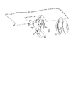
特に、図3〜図11を参照して、転倒防止機構について詳細に説明する。図3は本発明の実施例に係る転倒防止機構の部分を斜め上から見た斜視図である。本実施例に係る転倒防止機構13は、概略、画像形成装置の転倒を防止するために、床面から受ける反作用によりキャスター12と共に画像形成装置本体1及び給送装置11を支えることのできるストッパとしてのL字型スタンド14と、L字型スタンド14を保持するための保持部材15とを備えている。
<Detailed description of fall prevention mechanism>
In particular, the fall prevention mechanism will be described in detail with reference to FIGS. FIG. 3 is a perspective view of a part of the fall prevention mechanism according to the embodiment of the present invention as viewed obliquely from above. The
<<L字型スタンドのみの動作に関する詳細説明>>
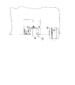
まず、特に、図3〜図5を参照して、L字型スタンド14のみの動作について詳細に説明する。図4及び図5は本発明の実施例に係る転倒防止機構の部分を斜め下から見た斜視図である。なお、図4はL字型スタンド14を立てて画像形成装置を所望の位置に設置する場合を示し、図5は画像形成装置を移動するためにL字型スタンド14を退避させた状態を示している。
<< Detailed explanation about operation of L-shaped stand only >>
First, in particular, the operation of only the L-shaped
L字型スタンド14は、床面から受ける反作用によりキャスター12と共に画像形成装置を支えることによって、画像形成装置の転倒を防止する転倒防止位置(図3,4に示す状態)、または画像形成装置の移動時に床に接触しないように床から離れる退避位置(図5に示す状態)のうちのいずれか一方に選択的に移動可能に構成されている。この点について、更に詳細に説明する。
The L-shaped
転倒防止の役目を果たすL字型スタンド14は、保持部材15に対して、回転支点軸1
6を中心に回転可能に保持されている。回転支点軸16は、画像形成装置の設置面に対して略平行になるように設けられている。これにより、L字型スタンド14は、長手方向の先端が床面(設置面)に対して当接する位置(あるいは、大量のシートが積載されたり、ユーザがもたれかかったりして、所定以上の重量負荷がかかった場合に当接するように、床面から僅かに離れた位置)から、その先端が床面から離れていく方向に回転移動させることができる。
The L-shaped
6 is held rotatably around the center. The
そして、画像形成装置の設置時に、L字型スタンド14を転倒防止位置に保持(固定)するための保持機構として、L字型スタンド14には凸部としてのボス17が設けられており、保持部材15には、このボス17に嵌合する凹部18が設けられている。本実施例ではボス17と凹部18を嵌合する時にクリック感が得られるように構成されている。そして、L字型スタンド14に対して、回転支点軸16の周りに回転する方向に所定以上の力(予め設定した一定以上の力)が作用すると、これらボス17と凹部18との嵌合は解除され、L字型スタンド14は回転する。
When the image forming apparatus is installed, the L-shaped
ここで、L字型スタンド14は、トグル機構を構成している。すなわち、回転支点軸16を中心として回転可能なL字型スタンド14と保持部材15との間には、第1付勢部材としてのトグルバネ19が掛けられている。このトグルバネ19は、一端がL字型スタンド14に設けられた軸(以下、B軸21と称する)に掛けられ、他端が保持部材15に設けられた軸(以下、A軸20と称する)に掛けられている。そして、L字型スタンド14が転倒防止位置にある場合、L字型スタンド14の回転支点軸16と、A軸20とB軸21(トグルバネ19の両端の固定部分)は一直線上に並ぶように構成されている。この時トグルバネ19の伸びは最大となるが、L字型スタンド14は、回転支点軸16に対して、時計方向及び反時計方向のいずれにも回転しない中立点の位置となる。そして、この位置で、L字型スタンド14は保持部材15に対して、上記ボス17と凹部18による凹凸嵌合により位置決めされた状態となる。このようにして、L字型スタンド14は転倒防止位置にセットされる。
Here, the L-shaped
この状態で、L字型スタンド14に対して、回転支点軸16に対して回転する方向に外力がかかり、L字型スタンド側のボス17と保持部材側の凹部18の嵌合を外すのに必要な力より大きい力が作用すると、凹凸嵌合が解除され、L字型スタンド14はトグル機構の中立点を外れる。すると、L字型スタンド14はトグルバネ19の収縮力により力の働いた方向に回転し、退避位置に移動する(図5に示す状態)。
In this state, an external force is applied to the L-shaped
以上のように、L字型スタンド14に対して回転支点軸16周りに回転する方向に力が働いた場合、つまり、回転支点軸16に対して垂直な方向に所定以上の外力が作用した場合には、L字型スタンド14が転倒防止位置にある状態であっても、L字型スタンド14は自動的に退避位置に移動する。なお、本実施例では、外力が作用していない状態においては、回転支点軸16は、装置正面に対して前後方向に伸びるように配置されている。したがって、装置正面に対して左右方向にのみL字型スタンド14に対して外力が働いた場合には、保持部材15が回転移動することなく、L字型スタンド14は、上述のように退避位置に自動的に回転移動する。
As described above, when a force is applied to the L-shaped
<<保持部材の動作を伴ったL字型スタンドの動作についての詳細説明>>
次に、特に、図6〜図11を参照して、保持部材15の動作を伴ったL字型スタンド14の動作について詳細に説明する。図6は本発明の実施例に係る転倒防止機構について、保持部材の取り付け部分が見えるようにした斜視図である。図7及び図8は本発明の実施例に係る転倒防止機構の部分を示す底面図である。なお、図7は外力が作用していない場合の状態を示し、図8は外力が作用した場合の状態を示している。図9〜図11は本発明の実施例に係る転倒防止機構の部分を斜め下から見た斜視図である。なお、図9〜図11
は保持部材15が旋回(回転)する方向に外力が作用した場合における、保持部材15とL字型スタンド14の動作の様子を示したものである。そして、図9は外力が作用した直後、図10は外力が作用している途中、図11は外力が作用しなくなった後の状態について、それぞれ示している。
<< Detailed explanation about operation of L-shaped stand with operation of holding member >>
Next, the operation of the L-shaped
Fig. 4 shows how the holding
装置正面に対して前後方向の成分を含む外力がL字型スタンド14に対して働いた場合には、L字型スタンド14だけでなく、保持部材15の動作も伴う。以下、この点について詳細に説明する。
When an external force including a component in the front-rear direction with respect to the front of the apparatus acts on the L-shaped
図6に示すように、保持部材15は、給送装置11の底面22に対して、装置の設置面に対して略垂直な軸23を中心に回転可能に構成されている。また、保持部材15に設けられた突起部15aが、給送装置11の底面22に設けられた円弧状の孔23aに挿入される構成となっている。これにより、保持部材15の回転可能な範囲が規制されている。この実施例では、保持部材15は、初期位置(上記の通り、回転支点軸16が、装置正面に対して前後方向に伸びるような位置)に対して、時計方向及び反時計方向に45度づつ回転できるように構成されている。
As shown in FIG. 6, the holding
そして、図7などに示すように、保持部材15と給送装置11との間に第2付勢部材としてのバネ24が設けられている。このバネ24が最も収縮した位置を初期位置として、保持部材15は止まっている。保持部材15が初期位置にある状態で、L字型スタンド14又は保持部材15に対して装置正面における前後方向に力が作用すると、図8に示すように、L字型スタンド14及び保持部材15は軸23を中心として回転する。
Then, as shown in FIG. 7 and the like, a
この時、力が大きく、L字型スタンド14及び保持部材15が軸23を中心に初期位置から45度の位置まで回転すると(図8及び図9参照)、装置正面に対する前後方向の力の45度方向成分が、L字型スタンド14に対して作用する。これにより、L字型スタンド14に対して、回転支点軸16周りに回転させる方向に力が働く。そして、この力が所定以上になると、上述のように、ボス17と凹部18による凹凸嵌合が解除されて、L字型スタンド14は転倒防止位置から退避位置まで自動的に回転する(図10参照)。
At this time, if the force is large and the L-shaped
そして、L字型スタンド14が退避位置に移動した後、外力が働かなくなると保持部材15はバネ24の力により初期位置へと戻される(図11参照)。
Then, after the L-shaped
<本実施例に係る転倒防止機構の優れた点>
以上のように、本実施例に係る転倒防止機構においては、L字型スタンド14と保持部材15との間にトグルバネ19を掛け、L字型スタンド14に所定以上の力が働くとL字型スタンド14が回転支点軸16周りに回転するトグル機構を構成し、また、L字型スタンド14を保持する保持部材15を、装置底面に対して旋回可能となるように構成した。
<Excellent point of the fall prevention mechanism according to this embodiment>
As described above, in the fall prevention mechanism according to the present embodiment, when the
このような構成により、L字型スタンド14に対してどの方向から外力が働いてもL字型スタンド14を退避させる事が可能となる。したがって、L字型スタンド14が転倒防止位置にある状態のまま、画像形成装置を移動させることによって、L字型スタンド14が段差へ突き当たってしまったり、障害物に衝突してしまったりした場合であっても、L字型スタンド14は自動的に退避位置に移動するため、L字型スタンド14や保持部材15などの破損を抑制することができる。
With such a configuration, the L-shaped
また、画像形成装置を所望の箇所に設置する場合には、L字型スタンド14をボス17と保持部材の凹部18とが嵌まり合うクリック位置(転倒防止位置)まで回転支点軸16に対して回転させるだけでよい。更に、画像形成装置を移動させる場合には、L字型スタンド14を転倒防止位置から少し回転させるだけで、L字型スタンド14は退避位置まで
自動的に回転する。このように、オペレーターによる面倒な操作を必要とすることなく、画像形成装置を設置または移動させることができる。
When the image forming apparatus is installed at a desired location, the L-shaped
また、外力が働かなくなると、保持部材15はバネ24の力により初期位置へと戻されることから、L字型スタンド14を再設置する場合の作業が容易になるという利点がある。すなわち、L字型スタンド14に対してトグル機構が動作できない方向に外力が働いた場合に、L字型スタンド14を回転させる方向に力が働くようにするために、保持部材15は回転可能に構成されている。しかしながら、本来、L字型スタンド14が転倒防止の役割を果たすのは、保持部材15が初期位置にあるときである。そのため、L字型スタンド14を再設置する場合には、保持部材15を初期位置に戻す必要がある。本実施例においては、保持部材15はバネ24の力により初期位置へと戻されることから、オペレーターが保持部材15を初期位置に戻す作業をしなくてもよいため、設置作業が容易となる。
Further, when the external force stops working, the holding
更に、画像形成装置のユーザが、L字型スタンド14に足を引っ掛けたとしても、L字型スタンド14は自動的に退避するため、安全性の面でも優れている。なお、本実施例においては、転倒防止機構を適用する装置として、画像形成装置を例にして説明したが、上述した転倒防止機構は、他の装置にも適用することができる。
Furthermore, even if the user of the image forming apparatus hooks his / her foot on the L-shaped
1 画像形成装置本体
1A 画像形成部
2 感光体ドラム
3 転写ローラ
4 レーザースキャナー
5 トナーカートリッジ
6 シート収納カセット
7 搬送ローラ
7A レジストローラ
8 定着手段
9 排出ローラ
10 排出部
11 給送装置
12 キャスター
13 転倒防止機構
14 L字型スタンド
15 保持部材
15a 突起部
16 回転支点軸
17 ボス
18 凹部
19 トグルバネ
20 A軸
21 B軸
22 底面
23 軸
23a 孔
24 バネ
DESCRIPTION OF
Claims (5)
床面から受ける反作用により転動体と共に前記装置を支えることによって、該装置の転倒を防止する転倒防止位置、または前記装置の移動時に床に接触しないように床から離れる退避位置のうちのいずれか一方に選択的に移動可能に設けられたストッパと、
該ストッパを装置の設置面に対して略平行な軸により回転可能に軸支する保持部材と、
前記ストッパが転倒防止位置から移動した場合に、前記ストッパを退避位置方向に向けて付勢する第1付勢部材と、を備え、
前記ストッパ及び前記保持部材のうちいずれか一方に凸部が設けられ、他方に前記凸部に嵌合する凹部が設けられており、これら凸部と凹部の嵌合により、前記ストッパが転倒防止位置にて保持され、
前記ストッパが所定以上の外力を受けると前記凸部と凹部との嵌合が解除されて、前記第1付勢部材の付勢力によって、前記ストッパは退避位置に移動するように構成されていることを特徴とする転倒防止機構。 In a fall prevention mechanism that is provided in a device having rolling elements for moving on the floor and prevents the device from falling when the device is installed,
By supporting the device together with the rolling element by a reaction received from the floor surface, either the fall prevention position for preventing the device from falling or the retreat position for leaving the floor so as not to contact the floor when the device is moved A stopper provided to be selectively movable ,
A holding member that rotatably supports the stopper by an axis substantially parallel to the installation surface of the apparatus;
A first urging member that urges the stopper toward the retracted position when the stopper moves from the fall prevention position;
One of the stopper and the holding member is provided with a convex portion, and the other is provided with a concave portion that fits into the convex portion. By fitting the convex portion and the concave portion, the stopper is prevented from falling. Held in
The stopper is configured such that when the stopper receives an external force of a predetermined level or more, the fitting between the convex portion and the concave portion is released, and the stopper is moved to the retracted position by the biasing force of the first biasing member. A fall prevention mechanism characterized by
前記ストッパが転倒防止位置にて保持された状態においては、前記バネが伸びた状態となり、かつ該ストッパが軸支されている部分と前記バネの両端の固定部分が一直線上に並ぶことによって、該ストッパに回転方向の力が作用しないように構成されていることを特徴とする請求項1乃至3のいずれか一つに記載の転倒防止機構。 Wherein the first biasing member is a spring having one end fixed to the stopper,
In the state where the stopper is held at the fall prevention position, the spring is in an extended state, and the portion where the stopper is pivotally supported and the fixed portions at both ends of the spring are aligned in a straight line. anti-tip mechanism according to any one of claims 1 to 3 force in the rotational direction the stopper is characterized in that it is configured not to act.
該カセットから搬送されるシート上に画像を形成する画像形成手段と、
装置本体が床上を移動可能にするために、前記装置本体の底面側に設けられる転動体と、を備える画像形成装置において、
前記装置本体の底面側であって、前記カセットが引き出される側に、請求項1乃至4のうちのいずれか一つに記載の転倒防止機構が備えられていることを特徴とする画像形成装置。 A cassette for stacking multiple sheets;
Image forming means for forming an image on a sheet conveyed from the cassette;
In order to enable the apparatus main body to move on the floor, an image forming apparatus comprising a rolling element provided on the bottom surface side of the apparatus main body,
A bottom side of the apparatus main body, on the side where the cassette is drawn out, the image forming apparatus characterized by being provided with anti-tip mechanism according to any one of claims 1 to 4.
Priority Applications (1)
| Application Number | Priority Date | Filing Date | Title |
|---|---|---|---|
| JP2004365391A JP4585845B2 (en) | 2004-12-17 | 2004-12-17 | Fall prevention mechanism and image forming apparatus |
Applications Claiming Priority (1)
| Application Number | Priority Date | Filing Date | Title |
|---|---|---|---|
| JP2004365391A JP4585845B2 (en) | 2004-12-17 | 2004-12-17 | Fall prevention mechanism and image forming apparatus |
Publications (3)
| Publication Number | Publication Date |
|---|---|
| JP2006171489A JP2006171489A (en) | 2006-06-29 |
| JP2006171489A5 JP2006171489A5 (en) | 2009-11-19 |
| JP4585845B2 true JP4585845B2 (en) | 2010-11-24 |
Family
ID=36672318
Family Applications (1)
| Application Number | Title | Priority Date | Filing Date |
|---|---|---|---|
| JP2004365391A Expired - Fee Related JP4585845B2 (en) | 2004-12-17 | 2004-12-17 | Fall prevention mechanism and image forming apparatus |
Country Status (1)
| Country | Link |
|---|---|
| JP (1) | JP4585845B2 (en) |
Families Citing this family (3)
| Publication number | Priority date | Publication date | Assignee | Title |
|---|---|---|---|---|
| JP5153267B2 (en) * | 2007-09-04 | 2013-02-27 | キヤノン株式会社 | Device support mechanism, sheet feeding device, and image forming apparatus |
| EP2451156A4 (en) * | 2009-06-29 | 2014-08-13 | Panasonic Corp | Vehicle-mounted video display device |
| JP6550956B2 (en) * | 2015-06-22 | 2019-07-31 | 富士ゼロックス株式会社 | Image forming device |
Citations (7)
| Publication number | Priority date | Publication date | Assignee | Title |
|---|---|---|---|---|
| JPS63127176U (en) * | 1987-02-10 | 1988-08-19 | ||
| JPH068578A (en) * | 1992-06-25 | 1994-01-18 | Ricoh Co Ltd | Paper feed device |
| JPH09236959A (en) * | 1996-02-28 | 1997-09-09 | Fuji Xerox Co Ltd | Foot for supporting equipment at standstill time |
| JPH10221911A (en) * | 1997-02-12 | 1998-08-21 | Fuji Xerox Co Ltd | Image forming device |
| JPH1128130A (en) * | 1997-07-10 | 1999-02-02 | Ricoh Co Ltd | Preventing device against overturning of appliance |
| JP2002252475A (en) * | 2001-02-27 | 2002-09-06 | Ricoh Co Ltd | Safety device against overturning |
| JP2003218544A (en) * | 2002-01-23 | 2003-07-31 | Ricoh Co Ltd | Overturn preventive mechanism |
-
2004
- 2004-12-17 JP JP2004365391A patent/JP4585845B2/en not_active Expired - Fee Related
Patent Citations (7)
| Publication number | Priority date | Publication date | Assignee | Title |
|---|---|---|---|---|
| JPS63127176U (en) * | 1987-02-10 | 1988-08-19 | ||
| JPH068578A (en) * | 1992-06-25 | 1994-01-18 | Ricoh Co Ltd | Paper feed device |
| JPH09236959A (en) * | 1996-02-28 | 1997-09-09 | Fuji Xerox Co Ltd | Foot for supporting equipment at standstill time |
| JPH10221911A (en) * | 1997-02-12 | 1998-08-21 | Fuji Xerox Co Ltd | Image forming device |
| JPH1128130A (en) * | 1997-07-10 | 1999-02-02 | Ricoh Co Ltd | Preventing device against overturning of appliance |
| JP2002252475A (en) * | 2001-02-27 | 2002-09-06 | Ricoh Co Ltd | Safety device against overturning |
| JP2003218544A (en) * | 2002-01-23 | 2003-07-31 | Ricoh Co Ltd | Overturn preventive mechanism |
Also Published As
| Publication number | Publication date |
|---|---|
| JP2006171489A (en) | 2006-06-29 |
Similar Documents
| Publication | Publication Date | Title |
|---|---|---|
| US7857303B2 (en) | Sheet feeding apparatus and image forming apparatus | |
| JP2003182861A (en) | Sheet feeding device and image forming device using it | |
| KR20110052559A (en) | Sheet feeding apparatus and image forming apparatus | |
| JP2018128517A (en) | Fall prevention device and supply device | |
| JP2020183295A (en) | Sheet storage device and image formation device | |
| JP4585845B2 (en) | Fall prevention mechanism and image forming apparatus | |
| JP5282651B2 (en) | Sheet material discharging apparatus and image forming apparatus | |
| JP4613892B2 (en) | Paper feeding device and image forming apparatus having the same | |
| JP2016179907A (en) | Image formation apparatus | |
| JP5626031B2 (en) | Image forming apparatus | |
| JP2001072303A (en) | Sheet loading device and image forming device | |
| JP5153267B2 (en) | Device support mechanism, sheet feeding device, and image forming apparatus | |
| JP2000062971A (en) | Paper feeding cassette | |
| JP2006208757A (en) | Image forming apparatus | |
| JP3648956B2 (en) | Paper tray mechanism | |
| US20030016975A1 (en) | Image forming apparatus | |
| JP4437876B2 (en) | Paper feeding device and image forming apparatus | |
| JP3255277B2 (en) | Safety device for opening and closing members | |
| JP2004109509A (en) | Image forming apparatus | |
| JP2006126605A (en) | Image forming apparatus | |
| JPH07116035A (en) | Overturning preventive device for apparatus having caster | |
| JP7322441B2 (en) | Equipment equipped with anti-tipping members and anti-tipping devices | |
| JP5652423B2 (en) | Image forming apparatus | |
| JP2021098572A (en) | Sheet stacking device and image forming apparatus equipped with the same | |
| JPH0423862Y2 (en) |
Legal Events
| Date | Code | Title | Description |
|---|---|---|---|
| A621 | Written request for application examination |
Free format text: JAPANESE INTERMEDIATE CODE: A621 Effective date: 20071212 |
|
| A521 | Written amendment |
Free format text: JAPANESE INTERMEDIATE CODE: A523 Effective date: 20091001 |
|
| A977 | Report on retrieval |
Free format text: JAPANESE INTERMEDIATE CODE: A971007 Effective date: 20100827 |
|
| TRDD | Decision of grant or rejection written | ||
| A01 | Written decision to grant a patent or to grant a registration (utility model) |
Free format text: JAPANESE INTERMEDIATE CODE: A01 Effective date: 20100831 |
|
| A01 | Written decision to grant a patent or to grant a registration (utility model) |
Free format text: JAPANESE INTERMEDIATE CODE: A01 |
|
| A61 | First payment of annual fees (during grant procedure) |
Free format text: JAPANESE INTERMEDIATE CODE: A61 Effective date: 20100906 |
|
| R150 | Certificate of patent or registration of utility model |
Free format text: JAPANESE INTERMEDIATE CODE: R150 |
|
| FPAY | Renewal fee payment (event date is renewal date of database) |
Free format text: PAYMENT UNTIL: 20130910 Year of fee payment: 3 |
|
| LAPS | Cancellation because of no payment of annual fees |