EP2033766A1 - Automated filament winding system - Google Patents
Automated filament winding system Download PDFInfo
- Publication number
- EP2033766A1 EP2033766A1 EP08011601A EP08011601A EP2033766A1 EP 2033766 A1 EP2033766 A1 EP 2033766A1 EP 08011601 A EP08011601 A EP 08011601A EP 08011601 A EP08011601 A EP 08011601A EP 2033766 A1 EP2033766 A1 EP 2033766A1
- Authority
- EP
- European Patent Office
- Prior art keywords
- mandrel
- fiber bundle
- winding
- around
- wound
- Prior art date
- Legal status (The legal status is an assumption and is not a legal conclusion. Google has not performed a legal analysis and makes no representation as to the accuracy of the status listed.)
- Granted
Links
Images











Classifications
-
- B—PERFORMING OPERATIONS; TRANSPORTING
- B29—WORKING OF PLASTICS; WORKING OF SUBSTANCES IN A PLASTIC STATE IN GENERAL
- B29C—SHAPING OR JOINING OF PLASTICS; SHAPING OF MATERIAL IN A PLASTIC STATE, NOT OTHERWISE PROVIDED FOR; AFTER-TREATMENT OF THE SHAPED PRODUCTS, e.g. REPAIRING
- B29C53/00—Shaping by bending, folding, twisting, straightening or flattening; Apparatus therefor
- B29C53/80—Component parts, details or accessories; Auxiliary operations
- B29C53/82—Cores or mandrels
- B29C53/821—Mandrels especially adapted for winding and joining
- B29C53/828—Arrangements comprising a plurality of cores or mandrels, e.g. to increase production speed
-
- B—PERFORMING OPERATIONS; TRANSPORTING
- B29—WORKING OF PLASTICS; WORKING OF SUBSTANCES IN A PLASTIC STATE IN GENERAL
- B29C—SHAPING OR JOINING OF PLASTICS; SHAPING OF MATERIAL IN A PLASTIC STATE, NOT OTHERWISE PROVIDED FOR; AFTER-TREATMENT OF THE SHAPED PRODUCTS, e.g. REPAIRING
- B29C53/00—Shaping by bending, folding, twisting, straightening or flattening; Apparatus therefor
- B29C53/56—Winding and joining, e.g. winding spirally
- B29C53/58—Winding and joining, e.g. winding spirally helically
- B29C53/60—Winding and joining, e.g. winding spirally helically using internal forming surfaces, e.g. mandrels
- B29C53/602—Winding and joining, e.g. winding spirally helically using internal forming surfaces, e.g. mandrels for tubular articles having closed or nearly closed ends, e.g. vessels, tanks, containers
-
- B—PERFORMING OPERATIONS; TRANSPORTING
- B29—WORKING OF PLASTICS; WORKING OF SUBSTANCES IN A PLASTIC STATE IN GENERAL
- B29L—INDEXING SCHEME ASSOCIATED WITH SUBCLASS B29C, RELATING TO PARTICULAR ARTICLES
- B29L2031/00—Other particular articles
- B29L2031/712—Containers; Packaging elements or accessories, Packages
- B29L2031/7154—Barrels, drums, tuns, vats
- B29L2031/7156—Pressure vessels
Definitions
- the present invention relates to a filament winding automated system having an automated production line based on a filament winding method.
- a filament winding device is a device that manufactures hollow containers such as pressure tanks or pipes on the basis of a filament winding method (see, for example, the Japanese Patent Application (Tokugan) No. 2007-34723 and the Japanese Patent Application Publication (Tokkai-Hei) No. 10-119138 ).
- the filament winding method manufactures products (pressure tanks or the like) by winding a fiber bundle around a mandrel (liner).
- the fiber bundle is made of, for example, a textile material formed using a textile material such as glass fibers and a synthetic resin.
- the fi lament winding device winds a fiber bundle paid out from a head portion, around a mandrel.
- the head portion is composed of a hoop winding head that winds the fiber bundle around the mandrel in hoop form, and a helical winding head that winds the fiber bundle around the mandrel in helical form.
- the fiber bundle is wound around the mandrel substantially perpendicularly to an axial direction of the mandrel ( Figure 5A ).
- the fiber bundle is wound around the mandrel at a predetermined angle to the axial direction of the mandrel ( Figures 5B and 5C ).
- the filament winding device winds the fiber bundle around the mandrel installed at a winding position.
- the filament winding device installs the mandrel at the winding position to start winding, and after the winding is completed, discharges the mandrel from the winding position.
- the operation of installing and discharging the mandrel is manually performed by an operator. Moreover, at the beginning of the winding, the operator fixes a starting end to the mandrel, and at the end of the winding, cuts the fiber bundle from the mandrel.
- an object of the present invention is to provide a filament winding automated system that enables an increase in production efficiency and a reduction in costs.
- a filament winding automated system comprises a winding device winding a fiber bundle paid out from a head portion, around a mandrel, an installing device installing the mandrel around which no fiber bundle has been wound yet, at a winding position, a discharging device discharging the mandrel around which the fiber bundle has already been wound, from the winding position, a delivery device holding and delivering the fiber bundle from the mandrel around which the fiber bundle has already been wound to a mandrel around which no fiber bundle has been wound yet, and a cutting device cutting the fiber bundle.
- the delivery device holds the fiber bundle paid out from the head portion
- the cutting device cuts and separates the fiber bundle from the mandrel around which the fiber bundle has already been wound
- the discharging device discharges the mandrel around which the fiber bundle has already been wound
- the installing device installs the mandrel around which no fiber bundle has been wound yet
- the winding device starts winding the fiber bundle held by the delivery device, around the mandrel around which no fiber bundle has been wound yet.
- the head portion comprises a hoop winding head winding the fiber bundle around mandrel in hoop form
- the hoop winding head comprises a bobbin from which the fiber bundle is paid out to the mandrel and a revolving mechanism revolving the bobbin in a circumferential direction of the mandrel, and reciprocates relative to the mandrel in an axial direction of the mandrel.
- the head portion comprises a helical winding head winding the fiber bundle around the mandrel in helical form, and reciprocates relative to the mandrel in an axial direction of the mandrel.
- the filament winding automated system comprises the installing device and the discharging device.
- the installing device installs the mandrel around which no fiber bundle has been wound yet, at the winding position.
- the discharging device discharges the mandrel around which the fiber bundle has already been wound, from the winding position. Thus, the operator need not install the mandrel at the winding position or discharge the mandrel from the winding position.
- the filament winding automated system comprises the delivery device and the cutting device.
- the delivery device holds and delivers the fiber bundle from the mandrel around which the fiber bundle has already been wound to the mandrel around which no fiber bundle has been wound yet.
- the cutting device cuts the fiber bundle.
- the operator need not attach the starting end of the fiber bundle to the mandrel at the beginning of the winding or cut and separate the fiber bundle from the mandrel at the end of the winding.
- the filament winding automated system according to the present invention allows almost all of the production line to be automated to sharply reduce the number of operations performed by the operator and the time required for the operations, enabling an increase in production efficiency and a reduction in labor and costs required.
- FIG. 1 is a partly omitted perspective view showing a filament winding automated system according to a first embodiment.
- the filament winding automated system comprises a winding device I and a supply portion 2.
- the winding device 1 winds a fiber bundle R around a mandrel M.
- the supply portion 2 comprises support portions 21, 21, and a plurality of creels 20 in each of the creel support portions 21, 21.
- the fiber bundle R is wound around and housed on each of the creels 20.
- a fiber bundle R is made of, for example, a textile material formed using a textile material such as glass fibers and a synthetic resin.
- the supply portion 2 supplies the fiber bundle R drawn out from each creel 20 to the winding device 1.
- the fiber bundle R is pre-impregnated with a thermosetting synthetic resin material.
- the fiber bundle R may not be impregnated with any resin.
- a resin impregnating device (not shown in the drawings) is provided between the winding device 1 and the supply portion 2. The resin impregnating device applies the resin to the fiber bundle R drawn out from the creel 20 and supplies the resulting fiber bundle R to the winding device 1.
- a plurality of mandrels M are arranged on each of the opposite sides (the side closer to the reader and the side farther from the reader) of the winding device 1.
- the plurality of mandrels M1 around which no fiber bundle has been wound yet are arranged in front of the winding device 1 (closer to the reader).
- the plurality of mandrels M2 around which the fiber bundle has already been wound are arranged in front of the winding device 1 (farther to the reader).
- the mandrels M1, M2 are arranged at a first end (in the left of the figures) of the winding device 1.
- FIG 2 is an enlarged perspective view showing the winding device in Figure 1 .
- the winding device 1 comprises a machine body 10.
- the machine body 10 comprises a pair of parallel first guide rails 10a, 10a extending in a longitudinal direction 1a.
- the winding device 1 comprises a mandrel moving table 11 on the machine body 10. The mandrel moving table 11 reciprocates along the first guide rails 10a, 10a in the longitudinal direction 1a.
- the mandrel M comprises a spindle for mandrel S extending in a mandrel shaft direction Mc.
- the mandrel moving table 11 rotatably supports the spindle for mandrel S between opposite mandrel rotating shafts 11a, 11b.
- the mandrel rotating shafts 11a, 11b rotate the mandrel M around a center shaft together with the spindle for mandrel S.
- the mandrel M is formed of high-strength aluminum, metal, rein, or the like and shaped so as to have a cylindrical portion Ma and dome portions Mb arranged on the opposite sides of the cylindrical portion Ma ( Figure 5 ).
- the spindle for mandrel S is removably fixed to the mandrel M.
- the longitudinal direction 1a of the machine body 10 corresponds to a mandrel shaft direction Mc.
- the material, shape, or the like of the mandrel M may be varied depending on the product.
- the winding device 1 comprises one hoop winding head 12 and one helical winding head 13.
- the hoop winding head 12 winds the fiber bundle R around the mandrel M in hoop form.
- the helical winding head 13 winds the fiber bundle R around the mandrel M in helical form.
- the winding device 1 is drivingly controlled by a control section 6.
- the control section 6 controls reciprocation of the mandrel moving table 11 and rotation of the mandrel M via the mandrel rotating shafts 11a, 11b.
- the control section 6 controls reciprocation of the hoop winding head 12, revolving of a bobbin 12b, and the like. Furthermore, the control section 6 controls driving side wall portions 11b, 11b of the mandrel moving table 11, described below.
- the hoop winding head 12 comprises a main body portion 12a.
- the main body portion 12a comprises an insertion portion 12d having a central opening.
- the hoop winding head 12 allows the mandrel M to be inserted through the insertion portion 12d.
- the machine body 10 comprises a pair of guide rails 10a, 10b extending in the longitudinal direction 1a.
- the hoop winding head 12 comprises a moving base 12f and moves along the second guide rails 10b, 10b in the longitudinal direction 1a.
- the hoop winding head 12 reciprocates with the mandrel M inserted through the insertion portion 12d.
- the hoop winding head 12 comprises a plurality of (in the present embodiment, two) bobbins 12b, 12b around each of which the fiber bundle R is wound and housed.
- the hoop winding head 12 comprises a revolving mechanism.
- the revolving mechanism comprises a groove 12c formed along a mandrel circumferential direction Md and a driving section 12e such as a motor; the guide groove 12c and the driving section 12e are arranged around the periphery of the insertion portion 12d.
- the bobbins 12b, 12b are revolved along the guide groove 12c by means of power from the driving section 12e.
- the fiber bundle R paid out from each of the revolving bobbins 12b, 12b is wound around the mandrel M.
- the helical winding head 13 comprises a main body portion 13a.
- the main body portion 13a comprises an insertion portion 13d having a central opening.
- the helical winding head 13 allows the mandrel M to be inserted through the insertion portion 13d.
- the position of the helical winding head 13 is fixed in a central portion of the machine body 10 in the longitudinal direction 1a.
- the mandrel moving table 11 reciprocates.
- the helical winding head 13 reciprocates in the longitudinal direction 1a relative to the mandrel M.
- the helical winding head 13 winds the fiber bundle R drawn out from the supply portion 2, around the mandrel M.
- the helical winding head 13 comprises an annular guide ring portion 15 located around the periphery of the insertion portion 13d and extending along the mandrel circumferential direction Md.
- the main body portion 13a comprises tension portions 13b, 13b on the opposite sides of the guide ring portion 15.
- the helical winding head 13 comprises guide rollers 13c, 13c on the opposite sides of the main body portion 13a.
- the helical winding head 13 uses the guide rollers 13c, 13c to guide the fiber bundles R drawn out from the creel 20 to the tension portions 13b, 13b.
- the tension portions 13b, 13b apply a predetermined resin and tension to the fiber bundles R.
- the predetermined tension applied to the fiber bundles R by the tension portions 13b, 13b enables the fiber bundles R to be firmly wound around the mandrel M.
- Figure 3 is a front view showing the helical winding head 13.
- the helical winding head 13 comprises a plurality of ring-like auxiliary guides 13e.
- the auxiliary guides 13e are arranged along the outside of the guide ring portion 15.
- the fiber bundles R drawn out from the creels 20 are fed from the opposite sides of the helical winding head 13 through the guide rollers 13c to the tension portions 13b.
- the plurality of fiber bundles R are guided from the tension portions 13b via the auxiliary guides 13e to the guide ring portion 15.
- the plurality of fiber bundles R are guided to the mandrel M via a plurality of guide holes 15a formed along the guide ring portion 15.
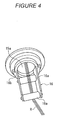
- Figure 4 is a perspective view showing a fiber opening guide.
- the fiber opening guide 16 is provided inside the guide ring portion 15 of the helical winding head 13 for each of the guide holes 15a.
- the fiber opening guide 16 comprises a pair of rotatable fiber opening rollers 16a, 16b.
- the fiber opening rollers 16a, 16a are arranged parallel to each other in a radial direction of the guide hole 15a.
- the fiber opening guide 16 comprises a rotating base 16b that is rotatable around the center of the guide hole 15a.
- the rotating base 16b supports the fiber opening rollers 16a, 16b.
- the fiber bundle R is inserted between the paired fiber opening guides 16a, 16a of the fiber opening guide 16.
- the fiber opening guide 16 rotates freely to allow the fiber opening rollers 16a, 16a to wind the fiber bundle R around the mandrel M in a fiber opening condition (with the width of the fiber bundle R increased).
- Figure 5 is a side view showing hoop winding and helical winding.
- the fiber bundle R is wound substantially perpendicularly to the mandrel shaft direction Mc.
- the fiber bundle R is wound around the mandrel M at the predetermined angle ⁇ ( ⁇ 1, ⁇ 2) to the mandrel shaft direction Mc.
- the hoop winding head 12 is used for the hoop winding.
- the helical winding head 13 is used for the helical winding.
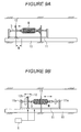
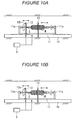
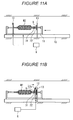
- Figures 6 to 13 are side views showing a manufacturing process in the fi lament winding automated system according to the first embodiment.
- the mandrel M is installed at and discharged from only a first end side (in the left of the figures) of the machine body 10.
- the filament winding automated system comprises a delivery device 3.
- the delivery device 3 comprises a delivery hand portion 30.
- the delivery hand portion 30 removably grips and holds a delivery spindle 30c.
- the delivery hand portion 30 comprises an expansion arm 30a that is expandable in a vertical direction.
- the delivery hand portion 30 comprises a moving base 30b that is movable in a horizontal direction along a guide rail (not shown in the drawings) provided on a ceiling portion T.
- the delivery hand portion 30 is drivingly controlled by the control section 6.
- the delivery spindle 30c holds a first delivery ring 31 and a second delivery ring 32.
- the delivery rings 31, 32 are slidable in an axial direction of the delivery spindle 30c while being regulated in a circumferential direction of the delivery spindle 30c.
- the delivery rings 31, 32 are coupled together by an installing and removing mechanism (not shown in the drawings) utilizing, for example, the magnetic force of a permanent magnet.
- the positions of the delivery rings 31, 32 are fixed by the delivery spindle 30c.
- the delivery rings 31, 32 are separated from each other or from the delivery spindle 30c during a subsequent step.
- the mandrel moving table 11 comprises mandrel rotating shafts 11a, 11a on the respective side wall portions 11b, 11b.
- the side wall portions 11b, 11b are set upright in the vertical direction for winding, and can be brought down in the horizontal direction to allow the mandrel M to be installed or discharged.
- the mandrel moving table 11 stands by with the opposite side wall portions 11b, 11b laid flat.
- the delivery hand portion 30 moves from a second end side (in the right of the figures) to the first end side (in the left of the figures) of the machine body 10 while gripping and holding the delivery spindle 30c.
- the delivery hand portion 30 positions the delivery spindle 30c inserted through the insertion portions 12d, 13d of the hoop winding head 12 and the helical winding head 13.
- the positions of the delivery rings 31, 32 are fixed by chuck mechanisms (not shown in the drawings) provided on the head portions 12, 13.
- the starting end of the fiber bundle R paid out from the head portion 12, 13 is secured to the first delivery ring 31 with a tape or the like.
- the filament winding automated system comprises an installing and discharging device 5.
- the installing and discharging device 5 comprises a first installing and discharging hand portion 51 and a second installing and discharging hand portion 52.
- the first and second installing and discharging hand portions 51, 52 removably grip the spindle for mandrel S to hold and move the mandrel M1 around which no fiber bundle has been wound yet and the mandrel M2 around which the fiber bundle has already been wound.
- first and second installing and discharging hand portions 51, 52 comprise expansion arms 51a, 52a and moving bases 51b, 52b, respectively.
- the first and second installing and discharging hand portions 51, 52 are drivingly controlled by the control section 6.
- the first and second installing and discharging hand portions 51, 52 grip and move the spindle for mandrel S on the opposite sides, respectively, of the mandrel M1 around which no fiber bundle has been wound yet.
- the first and second installing and discharging hand portions 51, 52 place the spindle for mandrel S such that a second end (in the right of the figures) of the spindle for mandrel S abuts against a first end (in the left of the figures) of the delivery spindle 30c.
- the first and second installing and discharging hand portions 51, 52 move the mandrel M1 toward the second end side (in the right of the figures) of the machine body 10.
- the delivery hand portion 30 moves the delivery spindle 30c toward the second end side (in the right of the figures) of the machine body 10.
- the spindle for mandrel S, and the delivery spindle 30c remain abutting against each other.
- the positions of the delivery rings 31, 32 are fixed by the chuck mechanisms (not shown in the drawings) on the head portions 12, 13.
- the delivery rings 31, 32 are thus fitted around (delivered to) the spindle for mandrel S through the delivery spindle 30c and held therein.
- the installing and removing mechanism (not shown in the drawings), fixing the position of the delivery rings 31, 32 to the delivery spindle 30c, exerts a weaker coupling force than the chuck mechanisms (not shown in the drawings).
- the above-described steps cause the delivery rings 31, 32 to leave the delivery spindle 30c.
- the installing and discharging device 5 comprises a third installing and discharging hand portion 53.
- the third installing and discharging hand portion 53 has the same configuration as that of the first installing and discharging hand portion 51 and the like, and comprises an expansion arm 53a and a moving base 53b.
- the third installing and discharging hand portion 53 is drivingly controlled by the control section 6.
- the third installing and discharging hand portion 53 holds the spindle for mandrel S at the second end side thereof (in the right of the figures).
- the second and third installing and discharging hand portions 52, 53 hold the spindle for mandrel S on the opposite sides, respectively, of the head portions 12, 13.
- the delivery hand portion 30 retracts the delivery spindle 30c.
- the second installing and discharging hand portion 52 releases the spindle for mandrel S and is retracted upward using the expansion arm 52a.
- the first and third installing and discharging hand portions 51, 53 move the mandrel M1 toward the second end side (in the right of the figures) of the machine body 10.
- the delivery ring 31 joins the mandrel M1.
- the mandrel moving table 11 rotatably supports the mandrel M1.
- the mandrel M1 around which no fiber bundle has been wound yet is installed at the winding position.
- the first and third installing and discharging hand portions 51, 53 releases the spindle for mandrel S and are retracted using the expansion arms 51a, 53a. Then, the installing and discharging hand portions 51 to 53 are retracted.
- the control section 6 allows the hoop winding head 12 to operate as described below.
- the hoop winding head 12 moves from the second end (in the right of the figures) to first end (in the left of the figures) of the mandrel M, while the bobbins 12b, 12b revolve.
- the mandrel moving table 11 is stopped, so that the mandrel M does not move or rotate.
- the fiber bundle R is paid out from each of the bobbins 12b, 12b.
- the fiber bundle R is wound around the mandrel M substantially orthogonally (slightly slantingly) to the mandrel axial direction Mc ( Figure 5 ) so that windings do not overlap one another but are arranged parallel to one another without any gap therebetween.
- the moving speed of the hoop winding head 12 and the revolving speed of the bobbins 12b, 12b are determined so as to achieve the above-described winding.
- the hoop winding head 12 moves from a second end (in the right of the figures) to a first end (in the left of the figures) of the mandrel cylindrical portion Ma ( Figure 5 ) to stack a layer of the fiber bundle R on the mandrel cylindrical portion Ma. Then, until a required number of layers of the fiber bundle R are stacked, the hoop winding head 12 reciprocates between one end (in the left of the figures) to other end (in the right of the figures) of the mandrel cylindrical portion Ma.
- the hoop winding head 12 is retracted to one end side (in the left of the figures) of the mandrel moving table 11 as shown in Figure 9A .
- the hoop winding head 12 is placed on the spindle for mandrel S at a predetermined distance W from the mandrel M.
- the control section 6 allows the mandrel moving table 11 to operate as described below.
- the mandrel moving table 11 moves so as to move the helical winding head 13 relative to the mandrel M from other end (in the right of the figures) to one end (in the left of the figures) of the mandrel M.
- the mandrel rotating shafts 11a, 11b rotate the mandrel M.
- the plurality of fiber bundles R paid out from the helical winding head 13 are wound at the winding angle ⁇ 1 to the mandrel axial direction Mc ( Figure 5 ) by a mandrel paralyzing portion so that windings do not overlap one another but are arranged parallel to one another without any gap therebetween.
- the moving speed of the mandrel moving table 11 (helical winding head 13) and the rotating speed of the mandrel rotating shaft 11a (mandrel M) are determined so as to achieve the above-described winding.
- the helical winding head 13 moves from other end (in the right of the figures) to one end (in the left of the figures) of the mandrel M to stack a layer of the fiber bundles R on the mandrel M. Then, until a required number of layers of the fiber bundles R are stacked, the helical winding head 13 reciprocates between one end (in the left of the figures) to other end (in the right of the figures) of the mandrel M.
- the hoop winding head 12 moves in synchronism with the mandrel moving table 11 so as to maintain a predetermined distance W from the mandrel M. Furthermore, the bobbins 12a, 12b revolve in the same direction as that of the mandrel M in synchronism with the rotation of the mandrel M so as to prevent extra fiber bundles R from being paid out from the bobbins 12b, 12b and wound around the spindle for mandrel S, by the rotation of the mandrel M.
- the mandrel moving table 11 moves to one end side (in the left of the figures) of the machine body 10.
- the helical winding head 13 is placed at other end side (in the right of the figures) of the mandrel moving stage 11.
- the fiber bundles R paid out from the helical winding head 13 are wound around the delivery rings 31, 32.
- the starting end is located on the first delivery ring (mandrel M-side delivery ring) 31.
- the terminal is located on the second delivery ring (the delivery ring located opposite the mandrel M) 32.
- the filament winding automated system comprises a cutting device 4.
- the cutting device 4 comprises a cutter portion 40.
- the cutter portion 40 comprises an expansion arm 40a and a moving base 40b.
- the cutter portion 40 is drivingly controlled by the control section 6.
- the cutter portion 40 places a cutting edge between the delivery rings 31, 32.
- the mandrel rotating shafts 11a, 11a rotate the delivery rings 31, 32 in conjunction with the mandrel M2.
- the fiber bundle R wound around the delivery rings 31, 32 is cut and separated between the delivery rings 31, 32.
- the first and third installing and discharging hand portions 51, 53 grip the opposite sides, respectively, of the spindle for mandrel S to hold the mandrel M2.
- the side wall portions 11b, 11b of the mandrel moving table 11 are brought down such that the mandrel M2 around which the fiber bundle has already been wound can be discharged from the winding position or the mandrel M2 around which no fiber bundle has been wound yet can be installed at the winding position.
- the delivery hand portion 30 moves the delivery spindle 30c.
- the delivery spindle 30c holds a third delivery ring 33.
- the delivery hand portion 30 causes one end (in the left of the figures) of the delivery spindle 30c to abut against other end (in the right of the figure) of the spindle for mandrel S.
- the first and third installing and discharging hand portions 51, 53 and the delivery hand portion 30 slightly move the mandrel M2 (spindle for mandrel S) and the delivery spindle 30c to one end side (in the left of the figures) of the machine body 10.
- the chuck mechanisms (not shown in the drawings) provided on the head portions 12, 13 release the first delivery ring 31 (the position of the second delivery ring 32 is fixed). Consequently, the first delivery ring 31 leaves the second delivery ring 32 together with the mandrel M2.
- the second installing and discharging portion 52 grips and holds the spindle for mandrel S between the first delivery ring 31 and the second delivery ring 32.
- the first and second installing and discharging portions 51, 52 hold the opposite sides, respectively, of the mandrel M2.
- the third installing and discharging portion 53 is retracted.
- the first and second installing and discharging portions 51, 52 and the delivery hand portion 30 move the spindle for mandrel S and the delivery spindle 30c to one end side (in the left of the figures) of the machine body 10.
- the second delivery ring 32 is fitted around (delivered to) the delivery spindle 30c through the spindle for mandrel S and held therein.
- the third delivery ring 33 is coupled to the second delivery ring 32 by the installing and removing mechanism (not shown in the drawings).
- the delivery spindle 30c holds the second delivery ring 32 and the third delivery ring 33.
- the first and second installing and discharging portions 51, 52 discharge the mandrel M2 around which the fiber bundle R has already been wound, from the winding position.
- the above-described manufacturing process completes one winding mandrel M2 (product).
- the fiber bundle R wound around the mandrel M2 is wound around the third delivery ring 33.
- the [cutting operation] ( Figures 12A ) and [discharging operation] ( Figure 12A to Figure 13B ) are performed.
- the third delivery ring 33 delivers the fiber bundle R from the mandrel M2 around which the fiber bundle R has already been wound to the mandrel M1 around which no fiber bundle has been wound yet.
- Figure 14 is a partly omitted perspective view showing a filament winding automated system according to the second embodiment.
- a plurality of the mandrels (M1, M2) are arranged on each of the opposite sides (the side closer to the reader and the side farther from the reader) of the winding device 1.
- the mandrels M (M1, M2) are arranged on each of one end side (in the left of the figures) and other end side (in the right of the figures) of the winding device 1.
- FIG 15 is an enlarged perspective view showing the winding device shown in Figure 14 .
- the winding device 1 comprises two hoop winding heads 12, 12' and the one helical head 13.
- the first hoop winding head 12 is located on one end side (in the left of the figures), and the second hoop winding head 12' is located on other end side (in the right of the figures).
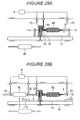
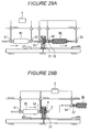
- Figures 16 to 30 are side views showing a manufacturing process in the filament winding automated system according to the second embodiment.
- the mandrels M are installed on and discharged from each of one end side (in the left of the figures) and other end side (in the right of the figures) of the machine body 10.
- the control section 6 allows the first and second installing and discharging hand portions 51, 52 grip and hold one of the mandrels M1 which are located on one end side (in the left of the figures) and around which no fiber bundle M1 has been wound yet.
- the first and second installing and discharging hand portion 51, 52 then move the mandrel M1 toward the mandrel moving table 11.
- the mandrel M1 holds the first delivery ring 31 and the second delivery ring 32 on other end side (in the right of the figures) of the spindle S for the mandrel M1.
- the rotation of the first delivery ring 31 and the second delivery ring 32 in the circumferential direction of the spindle for mandrel S is regulated by spline coupling or the like.
- the opposite side wall portions 11b, 11b of the mandrel moving table 11 are brought down so as to allow the mandrel M1 to move to the winding position.
- the first and second installing and discharging hand portions 51, 52 release the mandrel M1 and are retracted.
- the starting end of the fiber bundle R paid out from the head portions 12, 12', and 13 is fixed to the first delivery ring (mandrel M1-side delivery ring) 31.
- the positions of the first delivery ring 31 and the second delivery ring 32 are fixed by the chuck mechanisms (not shown in the drawings) provided on the head portions 12, 12' 13.
- the first delivery ring 31 is coupled to the mandrel M1 by a coupling mechanism (not shown in the drawings) such as a hook.
- the first delivery ring 31 and the second delivery ring 32 are coupled together by the installing and removing mechanism (not shown in the drawings) utilizing, for example, the magnetic force of the permanent magnet.
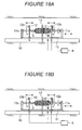
- the control section 6 allows the first hoop winding head 12 to operate. Until a require number of layers of the fiber bundle R are stacked, the first hoop winding head 12 reciprocates between one end (in the left of the figures) and other end (in the right of the figures) of the mandrel cylindrical portion Ma ( Figure 5 ). The mandrel moving table 11 and the second hoop winding head 12' are stopped.
- the first hoop winding head 12 is retracted to one end side (in the left of the figures) of the mandrel moving table 11 as shown in Figure 17B .
- the first hoop winding head 12 is located on the spindle for mandrel S at the predetermined distance from the mandrel M.
- the control section 6 allows the mandrel moving table 11 to operate. Until a required number of layers of the fiber bundle R are stacked (winding angle ⁇ 1), the mandrel moving table 11 moves relative to the mandrel M so as to reciprocate between one end (in the left of the figures) and other end (in the right of the figures) of the mandrel M.
- the first hoop winding head 12 moves so as to maintain the predetermined distance W from the mandrel M, and the second hoop winding head 12' moves so as to maintain the position of other end (in the right of the figures) of the mandrel M.
- the second hoop winding head 12' moves to other end side (in the right of the figures) of the mandrel moving table 11.
- the fiber bundle R paid out from the hoop winding head 12' is wound around the first delivery ring 31 and the second delivery ring 32.
- the mandrel moving table 11 moves to one end side (in the left of the figures) of the machine body 10.
- the helical winding head 13 is placed at other end side (in the right of the figures) of the mandrel M2.
- the fiber bundle R paid out from the helical winding head 13 is wound around the first delivery ring 31 and the second delivery ring 32.
- the first hoop winding head 12 moves to other end side (in the right of the figures) of the mandrel M2.
- the fiber bundle R paid out from the first hoop winding head 12 is wound around the first delivery ring 31 and the second delivery ring 32.
- the fiber bundle R paid out from the head portions 12, 12' 13 is wound and held around the first delivery ring 31 and the second delivery ring 32.
- the cutter portion 40 places the cutting edge between the first delivery ring 31 and the second delivery ring 32.
- the mandrel rotating shafts 11a, 11a rotate the first delivery ring 31 and the second delivery ring 32 in conjunction with the mandrel M.
- the fiber bundle R wound around the first delivery ring 31 and the second delivery ring 32 is cut and separated between the first delivery ring 31 and the second delivery ring 32.
- the installing and discharging device 5 comprises a fourth installing and discharging hand portion 54, and a fifth installing and discharging hand portion 55.
- the fourth and fifth installing and discharging hand portions 54, 55 have the same configuration as that of the first hand portion 30 and the like, and are drivingly controlled by the control section 6.
- the opposite side wall portions 11b, 11b of the mandrel moving head 11 are brought down so as to allow the mandrel M2 to be discharged from the winding position or to allow the mandrel M1 to move to the winding position.
- the control section 6 allows the fourth and fifth installing and discharging hand portions 54, 55 to move while gripping and holding the mandrel M1 around which no fiber bundle has been wound yet and which is located on other end side (in the right of the figures) of the machine body 10.
- One end (in the left of the figures) of the spindle S for the mandrel M1 (in the right of the figures) abuts against other end (in the right of the figure) of the spindle S for the mandrel M2 (in the left of the figures).
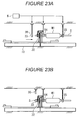
- the chuck mechanisms (not shown in the drawings) provided on the head portions 12, 12', 13 release the first delivery ring 31 (the position of the second delivery ring 32 is fixed). Consequently, the first delivery ring 31 leaves the second delivery ring 32 together with the mandrel M2.
- the second installing and discharging portion 52 grips and holds the spindle S for the mandrel M2 (in the left of the figures) between the first delivery ring 31 and the second delivery ring 32.
- the first and second installing and discharging portions 51, 52 hold the opposite sides, respectively, of the mandrel M2.
- the third installing and discharging portion 53 is retracted.
- the first, second, fourth, and fifth installing and discharging portions 51, 52, 54, 55 move the mandrel M2 (spindle for mandrel S) and the mandrel M1 (spindle for mandrel S) to one end side (in the left of the figures) of the machine body 10.
- the second delivery ring 32 is fitted around (delivered to) the spindle S for the mandrel M1 (in the right of the figures) through the spindle S for the mandrel M2 (in the left of the figures) and held therein.
- the first and second installing and discharging portions 51, 52 discharge the mandrel M2 around which the fiber bundle R has already been wound, from the winding position.
- the above-described manufacturing process completes one winding mandrel M2 (product).
- the fiber bundle R paid out from the head portions 12, 12', 13 is wound and held around the second delivery ring 32.
- control section 6 allows the delivery hand portion 30 to grip and hold the third delivery ring 33 and to move from one end side (in the left of the figures) of the machine body 10 to the mandrel M1 (in the right of the figures).
- the delivery hand portion 30 fits the third delivery ring 33 around the spindle S for the mandrel M1.
- the second delivery ring 32 and the third delivery ring 33 are coupled together by the installing and removing mechanism (not shown in the drawings) utilizing, for example, the magnetic fore of the permanent magnet.
- the delivery hand portion 30 is then retracted.
- the third and fifth installing and discharging hand portions 53, 55 are retracted.
- the positions of the second delivery ring 32 and the third delivery ring 33 are fixed by the chuck mechanisms (not shown in the drawings) provided on the head portions 12, 12', 13.
- the second delivery ring 32 is coupled to the mandrel M1 by the coupling mechanism (not shown in the drawings).
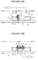
- the control section 6 allows the second hoop winding head 12' to operate. Until a require number of layers of the fiber bundle R are stacked, the second hoop winding head 12' reciprocates between one end (in the left of the figures) and other end (in the right of the figures) of the mandrel cylindrical portion Ma ( Figure 5 ). The mandrel moving table 11 and the first hoop winding head 12 are stopped.
- the fiber bundle R paid out from the second hoop winding head 12' is wound around the mandrel M1 through the second delivery ring 32.
- the second delivery ring 32 delivers the fiber bundle R from the mandrel M2 around which the fiber bundle R has already been wound to the mandrel M1 around which no fiber bundle R has been wound yet.
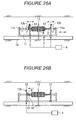
- the second hoop winding head 12' is retracted to other end side (in the right of the figures) of the mandrel moving table 11 as shown in Figure 25A .
- the second hoop winding head 12' is located on the spindle for mandrel S at the predetermined distance W from the mandrel M.
- the control section 6 allows the mandrel moving table 11 to operate. Until a required number of layers of the fiber bundle R are stacked, the mandrel moving table 11 reciprocates relative to the mandrel M between one end (in the left of the figures) and other end (in the right of the figures) of the mandrel M.
- the second hoop winding head 12' moves so as to maintain the predetermined distance W from the mandrel M, and the first hoop winding head 12 moves so as to maintain the position of one end (in the left of the figures) of the mandrel M.
- the first hoop winding head 12 moves to one end side (in the left of the figures) of the mandrel moving table 11.
- the fiber bundle R paid out from the hoop winding head 12 is wound around the second delivery ring 32 and the third delivery ring 33.
- the mandrel moving table 11 moves to other end side (in the right of the figures) of the machine body 10.
- the helical winding head 13 is placed at one end side (in the left of the figures) of the mandrel M2.
- the fiber bundle R paid out from the helical winding head 13 is wound around the second delivery ring 32 and the third delivery ring 33.
- the second hoop winding head 12' moves to one end side (in the left of the figures) of the mandrel moving table 11.
- the fiber bundle R paid out from the second hoop winding head 12' is wound around the second delivery ring 32 and the third delivery ring 33.
- the fiber bundle R paid out from the head portions 12, 12' 13 is wound and held around the second delivery ring 32 and the third delivery ring 33.
- the cutter portion 40 places the cutting edge between the second delivery ring 32 and the third delivery ring 33.
- the mandrel rotating shafts 11a, 11a rotate the second delivery ring 32 and the third delivery ring 33 in conjunction with the mandrel M2.
- the fiber bundle R wound around the second delivery ring 32 and the third delivery ring 33 is cut and separated between the second delivery ring 32 and the third delivery ring 33.
- the third and fifth installing and discharging hand portions 53, 55 grip and hold the mandrel M2.
- the opposite side wall portions 11b, 11b of the mandrel moving table 11 are brought down.
- the control section 6 allows the first and second installing and discharging hand portions 51, 52 to move while gripping and holding the mandrel M1 around which no fiber bundle has been wound yet and which is located on one end side (in the left of the figures) of the machine body 10.
- Other end (in the right of the figures) of the spindle S for the mandrel M1 (in the left of the figures) abuts against one end (in the left of the figure) of the spindle S for the mandrel M2 (in the right of the figures).
- the chuck mechanisms (not shown in the drawings) provided on the head portions 12, 12', 13 release the second delivery ring 32 (the position of the third delivery ring 33 is fixed). Consequently, the second delivery ring 32 leaves the third delivery ring 33 together with the mandrel M2.
- the fourth installing and discharging portion 54 grips and holds the spindle S for the mandrel M2 (in the left of the figures) between the second delivery ring 32 and the third delivery ring 33.
- the fourth and fifth installing and discharging portions 54, 55 hold the opposite sides, respectively, of the mandrel M2.
- the third installing and discharging portion 53 is retracted.
- the first, second, fourth, and fifth installing and discharging portions 51, 52, 54, 55 move the mandrel M2 (spindle for mandrel S) and the mandrel M1 (spindle for mandrel S) to other end side (in the right of the figures) of the machine body 10.
- the third delivery ring 33 is fitted around (delivered to) the spindle S for the mandrel M1 (in the left of the figures) through the spindle S for the mandrel M2 (in the right of the figures) and held therein.
- the fourth and fifth installing and discharging portions 54, 55 discharge the mandrel M2 around which the fiber bundle R has already been wound, from the winding position.
- the above-described manufacturing process further completes one winding mandrel M2 (product).
- the fiber bundle R paid out from the head portions 12, 12', 13 is wound and held around the third delivery ring 33.
- control section 6 allows the delivery hand portion 30 to grip and hold the fourth delivery ring 34 and to move from other end side (in the right of the figures) of the machine body 10 to the mandrel M1 (in the left of the figures).
- the delivery hand portion 30 fits the fourth delivery ring 34 around the spindle S for the mandrel M1.
- the delivery hand portion 30 is retracted.
- Figure 30B shows a condition corresponding to that shown in Figure 16A .
- the fiber bundle R wound around the mandrel M2 is wound around the fourth delivery ring 34 ( Figure 19B) to Figure 20 ). Subsequently, the [cutting operation], [installing and discharging operation] ( Figure 21 to Figure 30 ) are performed.
- the fourth delivery ring 34 delivers the fiber bundle R from the mandrel M2 around which the fiber bundle has already been wound to the mandrel M1 around which no fiber bundle has been wound yet.
- the production line can be automated by repeating the [installing operation ], [winding operation], [cutting operation], [discharging operation], and [ delivery operation] ( Figure 16B to Figure 30 ) as described above.
- the following operations can be performed on one end side (in the left side of the figures) and other end side (in the right side of the figures), respectively, of the machine body 10: the installing operation for the mandrel M1 around which no fiber bundle has been wound yet and the discharging operation for the mandrel M2 around which the fiber bundle R has been wound.
- the installing and discharging operations can thus be performed more efficiently.
Landscapes
- Engineering & Computer Science (AREA)
- Mechanical Engineering (AREA)
- Moulding By Coating Moulds (AREA)
Abstract
Description
- The present invention relates to a filament winding automated system having an automated production line based on a filament winding method.
- A filament winding device is a device that manufactures hollow containers such as pressure tanks or pipes on the basis of a filament winding method (see, for example, the Japanese Patent Application (Tokugan) No.
2007-34723 10-119138 - The fi lament winding device winds a fiber bundle paid out from a head portion, around a mandrel. The head portion is composed of a hoop winding head that winds the fiber bundle around the mandrel in hoop form, and a helical winding head that winds the fiber bundle around the mandrel in helical form. For the hoop winding, the fiber bundle is wound around the mandrel substantially perpendicularly to an axial direction of the mandrel (
Figure 5A ). For the helical winding, the fiber bundle is wound around the mandrel at a predetermined angle to the axial direction of the mandrel (Figures 5B and 5C ). - The filament winding device winds the fiber bundle around the mandrel installed at a winding position. To accomplish this, the filament winding device installs the mandrel at the winding position to start winding, and after the winding is completed, discharges the mandrel from the winding position. The operation of installing and discharging the mandrel is manually performed by an operator. Moreover, at the beginning of the winding, the operator fixes a starting end to the mandrel, and at the end of the winding, cuts the fiber bundle from the mandrel.
- Thus, the operator needs to perform various operations at the beginning and end of the winding. Disadvantageously, with an increase in the time required for operations performed by the operator and in the number of the operations, total production efficiency may decrease to increase costs.
- In view of the above-described problems, an object of the present invention is to provide a filament winding automated system that enables an increase in production efficiency and a reduction in costs.
- To accomplish this object, a filament winding automated system according to the present invention comprises a winding device winding a fiber bundle paid out from a head portion, around a mandrel, an installing device installing the mandrel around which no fiber bundle has been wound yet, at a winding position, a discharging device discharging the mandrel around which the fiber bundle has already been wound, from the winding position, a delivery device holding and delivering the fiber bundle from the mandrel around which the fiber bundle has already been wound to a mandrel around which no fiber bundle has been wound yet, and a cutting device cutting the fiber bundle.
- Moreover, in the filament winding automated system according to the present invention, after the winding is completed, the delivery device holds the fiber bundle paid out from the head portion, the cutting device cuts and separates the fiber bundle from the mandrel around which the fiber bundle has already been wound, the discharging device discharges the mandrel around which the fiber bundle has already been wound, the installing device installs the mandrel around which no fiber bundle has been wound yet, and the winding device starts winding the fiber bundle held by the delivery device, around the mandrel around which no fiber bundle has been wound yet.
- Preferably, the head portion comprises a hoop winding head winding the fiber bundle around mandrel in hoop form, and the hoop winding head comprises a bobbin from which the fiber bundle is paid out to the mandrel and a revolving mechanism revolving the bobbin in a circumferential direction of the mandrel, and reciprocates relative to the mandrel in an axial direction of the mandrel.
- Preferably, the head portion comprises a helical winding head winding the fiber bundle around the mandrel in helical form, and reciprocates relative to the mandrel in an axial direction of the mandrel.
- The filament winding automated system according to the present invention comprises the installing device and the discharging device. The installing device installs the mandrel around which no fiber bundle has been wound yet, at the winding position. The discharging device discharges the mandrel around which the fiber bundle has already been wound, from the winding position. Thus, the operator need not install the mandrel at the winding position or discharge the mandrel from the winding position.
- Moreover, the filament winding automated system according to the present invention comprises the delivery device and the cutting device. The delivery device holds and delivers the fiber bundle from the mandrel around which the fiber bundle has already been wound to the mandrel around which no fiber bundle has been wound yet. The cutting device cuts the fiber bundle. Thus, the operator need not attach the starting end of the fiber bundle to the mandrel at the beginning of the winding or cut and separate the fiber bundle from the mandrel at the end of the winding.
- Therefore, compared to conventional filament winding devices, the filament winding automated system according to the present invention allows almost all of the production line to be automated to sharply reduce the number of operations performed by the operator and the time required for the operations, enabling an increase in production efficiency and a reduction in labor and costs required.
- Other features, elements, processes, steps, characteristics and advantages of the present invention will become more apparent from the following detailed description of preferred embodiments of the present invention with reference to the attached drawings.
-
-
Figure 1 is a partly omitted perspective view showing a filament winding automated system according to a first embodiment. -
Figure 2 is an enlarged perspective view showing a winding device inFigure 1 . -
Figure 3 is a front view showing a helical windinghead 13. -
Figure 4 is a perspective view showing a fiber opening guide. -
Figure 5 is a side view showing hoop winding and helical winding. -
Figure 6 is a side view showing a manufacturing process in the filament winding automated system according to the first embodiment. -
Figure 7 is a side view continued fromFigure 6 . -
Figure 8 is a side view continued fromFigure 7 . -
Figure 9 is a side view continued fromFigure 8 . -
Figure 10 is a side view continued fromFigure 9 . -
Figure 11 is a side view continued fromFigure 10 . -
Figure 12 is a side view continued fromFigure 11 . -
Figure 13 is a side view continued fromFigure 12 . -
Figure 14 is a partly omitted perspective view showing a filament winding automated system according to a second embodiment. -
Figure 15 is an enlarged perspective view showing a winding device inFigure 14 . -
Figure 16 is a side view showing a manufacturing process in the filament winding automated system according to the second embodiment. -
Figure 17 is a side view continued fromFigure 16 . -
Figure 18 is a side view continued fromFigure 17 . -
Figure 19 is a side view continued fromFigure 18 . -
Figure 20 is a side view continued fromFigure 19 . -
Figure 21 is a side view continued fromFigure 20 . -
Figure 22 is a side view continued fromFigure 21 . -
Figure 23 is a side view continued fromFigure 22 . -
Figure 24 is a side view continued fromFigure 23 . -
Figure 25 is a side view continued fromFigure 24 . -
Figure 26 is a side view continued fromFigure 25 . -
Figure 27 is a side view continued fromFigure 26 . -
Figure 28 is a side view continued fromFigure 27 . -
Figure 29 is a side view continued fromFigure 28 . -
Figure 30 is a side view continued fromFigure 29 . - A filament winding automated system according to the present invention will be described below in detail with reference to the drawings.
- First, a first embodiment will be described.
-
Figure 1 is a partly omitted perspective view showing a filament winding automated system according to a first embodiment. The filament winding automated system comprises a winding device I and asupply portion 2. - The winding device 1 winds a fiber bundle R around a mandrel M.
The supply portion 2 comprisessupport portions creels 20 in each of thecreel support portions creels 20. - A fiber bundle R is made of, for example, a textile material formed using a textile material such as glass fibers and a synthetic resin. The
supply portion 2 supplies the fiber bundle R drawn out from eachcreel 20 to the winding device 1. - The fiber bundle R is pre-impregnated with a thermosetting synthetic resin material. The fiber bundle R may not be impregnated with any resin. In this case, a resin impregnating device (not shown in the drawings) is provided between the winding device 1 and the
supply portion 2. The resin impregnating device applies the resin to the fiber bundle R drawn out from thecreel 20 and supplies the resulting fiber bundle R to the winding device 1. - A plurality of mandrels M (M1, M2) are arranged on each of the opposite sides (the side closer to the reader and the side farther from the reader) of the winding device 1. The plurality of mandrels M1 around which no fiber bundle has been wound yet are arranged in front of the winding device 1 (closer to the reader). The plurality of mandrels M2 around which the fiber bundle has already been wound are arranged in front of the winding device 1 (farther to the reader). The mandrels M1, M2 are arranged at a first end (in the left of the figures) of the winding device 1.
-
Figure 2 is an enlarged perspective view showing the winding device inFigure 1 . The winding device 1 comprises amachine body 10. Themachine body 10 comprises a pair of parallelfirst guide rails longitudinal direction 1a. The winding device 1 comprises a mandrel moving table 11 on themachine body 10. The mandrel moving table 11 reciprocates along thefirst guide rails longitudinal direction 1a. - The mandrel M comprises a spindle for mandrel S extending in a mandrel shaft direction Mc. The mandrel moving table 11 rotatably supports the spindle for mandrel S between opposite
mandrel rotating shafts mandrel rotating shafts - When pressure tanks are manufactured, the mandrel M is formed of high-strength aluminum, metal, rein, or the like and shaped so as to have a cylindrical portion Ma and dome portions Mb arranged on the opposite sides of the cylindrical portion Ma (
Figure 5 ). The spindle for mandrel S is removably fixed to the mandrel M. Thelongitudinal direction 1a of themachine body 10 corresponds to a mandrel shaft direction Mc. The material, shape, or the like of the mandrel M may be varied depending on the product. - The winding device 1 comprises one
hoop winding head 12 and one helical windinghead 13. Thehoop winding head 12 winds the fiber bundle R around the mandrel M in hoop form. The helical windinghead 13 winds the fiber bundle R around the mandrel M in helical form. - The winding device 1 is drivingly controlled by a
control section 6. Thecontrol section 6 controls reciprocation of the mandrel moving table 11 and rotation of the mandrel M via themandrel rotating shafts control section 6 controls reciprocation of thehoop winding head 12, revolving of abobbin 12b, and the like. Furthermore, thecontrol section 6 controls drivingside wall portions - The
hoop winding head 12 comprises amain body portion 12a. Themain body portion 12a comprises aninsertion portion 12d having a central opening. Thehoop winding head 12 allows the mandrel M to be inserted through theinsertion portion 12d. - The
machine body 10 comprises a pair ofguide rails longitudinal direction 1a. Thehoop winding head 12 comprises a movingbase 12f and moves along thesecond guide rails longitudinal direction 1a. Thus, thehoop winding head 12 reciprocates with the mandrel M inserted through theinsertion portion 12d. - The
hoop winding head 12 comprises a plurality of (in the present embodiment, two)bobbins - The
hoop winding head 12 comprises a revolving mechanism. The revolving mechanism comprises agroove 12c formed along a mandrel circumferential direction Md and adriving section 12e such as a motor; theguide groove 12c and thedriving section 12e are arranged around the periphery of theinsertion portion 12d. Thebobbins guide groove 12c by means of power from thedriving section 12e. The fiber bundle R paid out from each of the revolvingbobbins - The helical winding
head 13 comprises amain body portion 13a. Themain body portion 13a comprises aninsertion portion 13d having a central opening. The helical windinghead 13 allows the mandrel M to be inserted through theinsertion portion 13d. The position of the helical windinghead 13 is fixed in a central portion of themachine body 10 in thelongitudinal direction 1a. - With the mandrel M inserted through the
insertion portion 13d of the helical windinghead 13, the mandrel moving table 11 reciprocates. Thus, the helical windinghead 13 reciprocates in thelongitudinal direction 1a relative to the mandrel M. - The helical winding
head 13 winds the fiber bundle R drawn out from thesupply portion 2, around the mandrel M. The helical windinghead 13 comprises an annularguide ring portion 15 located around the periphery of theinsertion portion 13d and extending along the mandrel circumferential direction Md. Themain body portion 13a comprisestension portions guide ring portion 15. Moreover, the helical windinghead 13 comprisesguide rollers main body portion 13a. - The helical winding
head 13 uses theguide rollers creel 20 to thetension portions tension portions tension portions -
Figure 3 is a front view showing the helical windinghead 13. The helical windinghead 13 comprises a plurality of ring-likeauxiliary guides 13e. The auxiliary guides 13e are arranged along the outside of theguide ring portion 15. - The fiber bundles R drawn out from the
creels 20 are fed from the opposite sides of the helical windinghead 13 through theguide rollers 13c to thetension portions 13b. The plurality of fiber bundles R are guided from thetension portions 13b via the auxiliary guides 13e to theguide ring portion 15. Moreover, the plurality of fiber bundles R are guided to the mandrel M via a plurality ofguide holes 15a formed along theguide ring portion 15. -
Figure 4 is a perspective view showing a fiber opening guide. Thefiber opening guide 16 is provided inside theguide ring portion 15 of the helical windinghead 13 for each of theguide holes 15a. Thefiber opening guide 16 comprises a pair of rotatablefiber opening rollers - The
fiber opening rollers guide hole 15a. Thefiber opening guide 16 comprises arotating base 16b that is rotatable around the center of theguide hole 15a. The rotatingbase 16b supports thefiber opening rollers - The fiber bundle R is inserted between the paired fiber opening guides 16a, 16a of the
fiber opening guide 16. Thus, even with a variation in a winding angle θ at which the fiber bundle R is wound around the mandrel M, thefiber opening guide 16 rotates freely to allow thefiber opening rollers -
Figure 5 is a side view showing hoop winding and helical winding. As shown inFigure 5A , for the hoop winding, the fiber bundle R is wound substantially perpendicularly to the mandrel shaft direction Mc. As shown inFigures 5B and 5C , for the helical winding, the fiber bundle R is wound around the mandrel M at the predetermined angle θ (θ1, θ2) to the mandrel shaft direction Mc. As described above, thehoop winding head 12 is used for the hoop winding. The helical windinghead 13 is used for the helical winding. -
Figures 6 to 13 are side views showing a manufacturing process in the fi lament winding automated system according to the first embodiment. In the first embodiment, the mandrel M is installed at and discharged from only a first end side (in the left of the figures) of themachine body 10. - As shown in
Figure 6A , the filament winding automated system comprises adelivery device 3. Thedelivery device 3 comprises adelivery hand portion 30. Thedelivery hand portion 30 removably grips and holds adelivery spindle 30c. Thedelivery hand portion 30 comprises anexpansion arm 30a that is expandable in a vertical direction. - Moreover, the
delivery hand portion 30 comprises a movingbase 30b that is movable in a horizontal direction along a guide rail (not shown in the drawings) provided on a ceiling portion T. Thedelivery hand portion 30 is drivingly controlled by thecontrol section 6. - The
delivery spindle 30c holds afirst delivery ring 31 and asecond delivery ring 32. On the basis of spline coupling or the like, the delivery rings 31, 32 are slidable in an axial direction of thedelivery spindle 30c while being regulated in a circumferential direction of thedelivery spindle 30c. - The delivery rings 31, 32 are coupled together by an installing and removing mechanism (not shown in the drawings) utilizing, for example, the magnetic force of a permanent magnet. The positions of the delivery rings 31, 32 are fixed by the
delivery spindle 30c. The delivery rings 31, 32 are separated from each other or from thedelivery spindle 30c during a subsequent step. - The mandrel moving table 11 comprises
mandrel rotating shafts side wall portions side wall portions - The mandrel moving table 11 stands by with the opposite
side wall portions delivery hand portion 30 moves from a second end side (in the right of the figures) to the first end side (in the left of the figures) of themachine body 10 while gripping and holding thedelivery spindle 30c. - As shown in
Figure 6B , thedelivery hand portion 30 positions thedelivery spindle 30c inserted through theinsertion portions hoop winding head 12 and the helical windinghead 13. - The positions of the delivery rings 31, 32 are fixed by chuck mechanisms (not shown in the drawings) provided on the
head portions head portion first delivery ring 31 with a tape or the like. - As shown in
Figure 7A , the filament winding automated system comprises an installing and dischargingdevice 5. The installing and dischargingdevice 5 comprises a first installing and discharginghand portion 51 and a second installing and discharginghand portion 52. The first and second installing and discharginghand portions - Like the
delivery hand portion 30, the first and second installing and discharginghand portions expansion arms bases hand portions control section 6. - The first and second installing and discharging
hand portions hand portions delivery spindle 30c. - As shown in
Figure 7B , the first and second installing and discharginghand portions machine body 10. In synchronism with this, thedelivery hand portion 30 moves thedelivery spindle 30c toward the second end side (in the right of the figures) of themachine body 10. Thus, the spindle for mandrel S, and thedelivery spindle 30c remain abutting against each other. - As described above, the positions of the delivery rings 31, 32 are fixed by the chuck mechanisms (not shown in the drawings) on the
head portions delivery spindle 30c and held therein. - The installing and removing mechanism (not shown in the drawings), fixing the position of the delivery rings 31, 32 to the
delivery spindle 30c, exerts a weaker coupling force than the chuck mechanisms (not shown in the drawings). Thus, the above-described steps cause the delivery rings 31, 32 to leave thedelivery spindle 30c. - The installing and discharging
device 5 comprises a third installing and discharginghand portion 53. The third installing and discharginghand portion 53 has the same configuration as that of the first installing and discharginghand portion 51 and the like, and comprises anexpansion arm 53a and a movingbase 53b. The third installing and discharginghand portion 53 is drivingly controlled by thecontrol section 6. - The third installing and discharging
hand portion 53 holds the spindle for mandrel S at the second end side thereof (in the right of the figures). Thus, the second and third installing and discharginghand portions head portions - As shown in
Figure 8A , thedelivery hand portion 30 retracts thedelivery spindle 30c. The second installing and discharginghand portion 52 releases the spindle for mandrel S and is retracted upward using theexpansion arm 52a. - Then, the first and third installing and discharging
hand portions machine body 10. Thus, thedelivery ring 31 joins the mandrel M1. - Then, the
side wall portions mandrel rotating shafts - Thus, the mandrel M1 around which no fiber bundle has been wound yet is installed at the winding position. The first and third installing and discharging
hand portions expansion arms hand portions 51 to 53 are retracted. - As shown in
Figure 8B , for hoop winding, thecontrol section 6 allows thehoop winding head 12 to operate as described below. Thehoop winding head 12 moves from the second end (in the right of the figures) to first end (in the left of the figures) of the mandrel M, while thebobbins - Thus, the fiber bundle R is paid out from each of the
bobbins Figure 5 ) so that windings do not overlap one another but are arranged parallel to one another without any gap therebetween. The moving speed of thehoop winding head 12 and the revolving speed of thebobbins - The
hoop winding head 12 moves from a second end (in the right of the figures) to a first end (in the left of the figures) of the mandrel cylindrical portion Ma (Figure 5 ) to stack a layer of the fiber bundle R on the mandrel cylindrical portion Ma. Then, until a required number of layers of the fiber bundle R are stacked, thehoop winding head 12 reciprocates between one end (in the left of the figures) to other end (in the right of the figures) of the mandrel cylindrical portion Ma. - After the hoop winding is completed, the
hoop winding head 12 is retracted to one end side (in the left of the figures) of the mandrel moving table 11 as shown inFigure 9A . Thehoop winding head 12 is placed on the spindle for mandrel S at a predetermined distance W from the mandrel M. - As shown in
Figure 9B , for helical winding, thecontrol section 6 allows the mandrel moving table 11 to operate as described below. The mandrel moving table 11 moves so as to move the helical windinghead 13 relative to the mandrel M from other end (in the right of the figures) to one end (in the left of the figures) of the mandrel M. In conjunction with the movement, themandrel rotating shafts - The plurality of fiber bundles R paid out from the helical winding
head 13 are wound at the winding angle θ1 to the mandrel axial direction Mc (Figure 5 ) by a mandrel paralyzing portion so that windings do not overlap one another but are arranged parallel to one another without any gap therebetween. The moving speed of the mandrel moving table 11 (helical winding head 13) and the rotating speed of themandrel rotating shaft 11a (mandrel M) are determined so as to achieve the above-described winding. - The helical winding
head 13 moves from other end (in the right of the figures) to one end (in the left of the figures) of the mandrel M to stack a layer of the fiber bundles R on the mandrel M. Then, until a required number of layers of the fiber bundles R are stacked, the helical windinghead 13 reciprocates between one end (in the left of the figures) to other end (in the right of the figures) of the mandrel M. - Moreover, the
hoop winding head 12 moves in synchronism with the mandrel moving table 11 so as to maintain a predetermined distance W from the mandrel M. Furthermore, thebobbins bobbins - When helical winding is performed at the winding angle θ2 (>θ1) as shown in
Figure 10A and subsequently performed at the winding angle θ1 again as shown inFigure 10B , the mandrel moving table 11 and thehoop winding head 12 move as described above. - As shown in
Figure 11A , after a required number of layers of helical winding are obtained, the mandrel moving table 11 moves to one end side (in the left of the figures) of themachine body 10. The helical windinghead 13 is placed at other end side (in the right of the figures) of themandrel moving stage 11. Thus, the fiber bundles R paid out from the helical windinghead 13 are wound around the delivery rings 31, 32. - As shown in
Figure 11B , after a required number of layers of hoop winding are obtained, thehoop winding head 12 moves to other end side (in the right of the figures) of the mandrel M2. Thus, the fiber bundle R paid out from thebobbin 12b is wound around the delivery rings 31, 32. - Consequently, the fiber bundles R paid out from the
head portions - As described above, for the fiber bundle R wound around the mandrel M2, the starting end is located on the first delivery ring (mandrel M-side delivery ring) 31. The terminal is located on the second delivery ring (the delivery ring located opposite the mandrel M) 32.
- As shown in
Figure 12A , the filament winding automated system comprises acutting device 4. Thecutting device 4 comprises acutter portion 40. Thecutter portion 40 comprises anexpansion arm 40a and a movingbase 40b. Thecutter portion 40 is drivingly controlled by thecontrol section 6. - The
cutter portion 40 places a cutting edge between the delivery rings 31, 32. Themandrel rotating shafts - As shown in
Figure 12B , the first and third installing and discharginghand portions side wall portions - The
delivery hand portion 30 moves thedelivery spindle 30c. Thedelivery spindle 30c holds athird delivery ring 33. Thedelivery hand portion 30 causes one end (in the left of the figures) of thedelivery spindle 30c to abut against other end (in the right of the figure) of the spindle for mandrel S. - As shown in
Figure 13A , with the spindle for mandrel S and thedelivery spindle 30c abutting against each other, the first and third installing and discharginghand portions delivery hand portion 30 slightly move the mandrel M2 (spindle for mandrel S) and thedelivery spindle 30c to one end side (in the left of the figures) of themachine body 10. - At this time, the chuck mechanisms (not shown in the drawings) provided on the
head portions second delivery ring 32 is fixed). Consequently, thefirst delivery ring 31 leaves thesecond delivery ring 32 together with the mandrel M2. - Then, the second installing and discharging
portion 52 grips and holds the spindle for mandrel S between thefirst delivery ring 31 and thesecond delivery ring 32. Thus, the first and second installing and dischargingportions portion 53 is retracted. - Moreover, with the spindle for mandrel S and the
delivery spindle 30c abutting against each other, the first and second installing and dischargingportions delivery hand portion 30 move the spindle for mandrel S and thedelivery spindle 30c to one end side (in the left of the figures) of themachine body 10. - As shown in
Figure 13B , thesecond delivery ring 32 is fitted around (delivered to) thedelivery spindle 30c through the spindle for mandrel S and held therein. Thethird delivery ring 33 is coupled to thesecond delivery ring 32 by the installing and removing mechanism (not shown in the drawings). Thedelivery spindle 30c holds thesecond delivery ring 32 and thethird delivery ring 33. - The first and second installing and discharging
portions - The fiber bundle R paid out from the
head portions second delivery ring 32.Figure 13B shows a condition corresponding to that shown inFigure 6B . - Subsequently, the above-described [installing operation] (
Figure 7A to Figure 8A ) and [winding operation] (Figure 8B to Figure 11C ) are performed. The fiber bundle R paid out from thehead portions second delivery ring 32. Consequently, thesecond delivery ring 32 delivers the fiber bundle R from the mandrel M2 around which the fiber bundle R has already been wound to the mandrel M1 around which no fiber bundle has been wound yet. - Then, after the winding operation is completed, the fiber bundle R wound around the mandrel M2 is wound around the
third delivery ring 33. Subsequently, the [cutting operation] (Figures 12A ) and [discharging operation] (Figure 12A to Figure 13B ) are performed. Thethird delivery ring 33 delivers the fiber bundle R from the mandrel M2 around which the fiber bundle R has already been wound to the mandrel M1 around which no fiber bundle has been wound yet. - With the [installing operation], [winding operation], [cutting operation], [discharging operation], and [delivery operation] (
Figures 7 to 13 ) repeated as described above, the production line can be automated and almost no operation needs to be performed by the operator. - Now, a second embodiment will be described. A detailed description will be given of arrangements of the second embodiment which are different from the corresponding ones of the first embodiment (arrangements of the second embodiment are the same as the corresponding ones of the first embodiment unless otherwise specified).
-
Figure 14 is a partly omitted perspective view showing a filament winding automated system according to the second embodiment. A plurality of the mandrels (M1, M2) are arranged on each of the opposite sides (the side closer to the reader and the side farther from the reader) of the winding device 1. In the second embodiment, the mandrels M (M1, M2) are arranged on each of one end side (in the left of the figures) and other end side (in the right of the figures) of the winding device 1. -
Figure 15 is an enlarged perspective view showing the winding device shown inFigure 14 . The winding device 1 comprises twohoop winding heads helical head 13. The firsthoop winding head 12 is located on one end side (in the left of the figures), and the secondhoop winding head 12' is located on other end side (in the right of the figures). -
Figures 16 to 30 are side views showing a manufacturing process in the filament winding automated system according to the second embodiment. In the second embodiment, the mandrels M are installed on and discharged from each of one end side (in the left of the figures) and other end side (in the right of the figures) of themachine body 10. - As shown in
Figure 16A , thecontrol section 6 allows the first and second installing and discharginghand portions hand portion - The mandrel M1 holds the
first delivery ring 31 and thesecond delivery ring 32 on other end side (in the right of the figures) of the spindle S for the mandrel M1. The rotation of thefirst delivery ring 31 and thesecond delivery ring 32 in the circumferential direction of the spindle for mandrel S is regulated by spline coupling or the like. The oppositeside wall portions - As shown in
Figure 16B , the oppositeside wall portions mandrel rotating shafts - The first and second installing and discharging
hand portions head portions - The positions of the
first delivery ring 31 and thesecond delivery ring 32 are fixed by the chuck mechanisms (not shown in the drawings) provided on thehead portions first delivery ring 31 is coupled to the mandrel M1 by a coupling mechanism (not shown in the drawings) such as a hook. Thefirst delivery ring 31 and thesecond delivery ring 32 are coupled together by the installing and removing mechanism (not shown in the drawings) utilizing, for example, the magnetic force of the permanent magnet. - As shown in
Figure 17A , for hoop winding, thecontrol section 6 allows the firsthoop winding head 12 to operate. Until a require number of layers of the fiber bundle R are stacked, the firsthoop winding head 12 reciprocates between one end (in the left of the figures) and other end (in the right of the figures) of the mandrel cylindrical portion Ma (Figure 5 ). The mandrel moving table 11 and the secondhoop winding head 12' are stopped. - After the hoop winding is completed, the first
hoop winding head 12 is retracted to one end side (in the left of the figures) of the mandrel moving table 11 as shown inFigure 17B . The firsthoop winding head 12 is located on the spindle for mandrel S at the predetermined distance from the mandrel M. - As shown in
Figure 18A , for helical winding, thecontrol section 6 allows the mandrel moving table 11 to operate. Until a required number of layers of the fiber bundle R are stacked (winding angle θ1), the mandrel moving table 11 moves relative to the mandrel M so as to reciprocate between one end (in the left of the figures) and other end (in the right of the figures) of the mandrel M. - In synchronism with the mandrel moving table 11, the first
hoop winding head 12 moves so as to maintain the predetermined distance W from the mandrel M, and the secondhoop winding head 12' moves so as to maintain the position of other end (in the right of the figures) of the mandrel M. - When helical winding is performed at the winding angle θ2 (>θ1) as shown in
Figure 18B and subsequently performed at the winding angle θ1 again as shown inFigure 19A , the mandrel moving table 11, and the first and secondhoop winding heads - As shown in
Figure 19B , the secondhoop winding head 12' moves to other end side (in the right of the figures) of the mandrel moving table 11. Thus, the fiber bundle R paid out from thehoop winding head 12' is wound around thefirst delivery ring 31 and thesecond delivery ring 32. - As shown in
Figure 20A , after a required number of layers of helical winding are obtained, the mandrel moving table 11 moves to one end side (in the left of the figures) of themachine body 10. The helical windinghead 13 is placed at other end side (in the right of the figures) of the mandrel M2. Thus, the fiber bundle R paid out from the helical windinghead 13 is wound around thefirst delivery ring 31 and thesecond delivery ring 32. - As shown in
Figure 20B , after a required number of layers of hoop winding are obtained, the firsthoop winding head 12 moves to other end side (in the right of the figures) of the mandrel M2. Thus, the fiber bundle R paid out from the firsthoop winding head 12 is wound around thefirst delivery ring 31 and thesecond delivery ring 32. - Consequently, the fiber bundle R paid out from the
head portions first delivery ring 31 and thesecond delivery ring 32. - As shown in
Figure 21A , thecutter portion 40 places the cutting edge between thefirst delivery ring 31 and thesecond delivery ring 32. Themandrel rotating shafts first delivery ring 31 and thesecond delivery ring 32 in conjunction with the mandrel M. Thus, the fiber bundle R wound around thefirst delivery ring 31 and thesecond delivery ring 32 is cut and separated between thefirst delivery ring 31 and thesecond delivery ring 32. - As shown in
Figure 21B , the first and third installing and discharginghand portions device 5 comprises a fourth installing and discharginghand portion 54, and a fifth installing and discharginghand portion 55. The fourth and fifth installing and discharginghand portions first hand portion 30 and the like, and are drivingly controlled by thecontrol section 6. - The opposite
side wall portions mandrel moving head 11 are brought down so as to allow the mandrel M2 to be discharged from the winding position or to allow the mandrel M1 to move to the winding position. Thecontrol section 6 allows the fourth and fifth installing and discharginghand portions machine body 10. One end (in the left of the figures) of the spindle S for the mandrel M1 (in the right of the figures) abuts against other end (in the right of the figure) of the spindle S for the mandrel M2 (in the left of the figures). - As shown in
Figure 22A , with the spindles for mandrel S, S abutting against each other, the first, third, fourth, and fifth installing and discharginghand portions machine body 10. - At this time, the chuck mechanisms (not shown in the drawings) provided on the
head portions second delivery ring 32 is fixed). Consequently, thefirst delivery ring 31 leaves thesecond delivery ring 32 together with the mandrel M2. - Then, the second installing and discharging
portion 52 grips and holds the spindle S for the mandrel M2 (in the left of the figures) between thefirst delivery ring 31 and thesecond delivery ring 32. Thus, the first and second installing and dischargingportions portion 53 is retracted. - Moreover, with the spindles for mandrel S, S abutting against each other, the first, second, fourth, and fifth installing and discharging
portions machine body 10. - Thus, the
second delivery ring 32 is fitted around (delivered to) the spindle S for the mandrel M1 (in the right of the figures) through the spindle S for the mandrel M2 (in the left of the figures) and held therein. - As shown in
Figure 22B , the first and second installing and dischargingportions head portions second delivery ring 32. - As shown in
Figure 23A , thecontrol section 6 allows thedelivery hand portion 30 to grip and hold thethird delivery ring 33 and to move from one end side (in the left of the figures) of themachine body 10 to the mandrel M1 (in the right of the figures). - As shown in
Figure 23B , thedelivery hand portion 30 fits thethird delivery ring 33 around the spindle S for the mandrel M1. Thesecond delivery ring 32 and thethird delivery ring 33 are coupled together by the installing and removing mechanism (not shown in the drawings) utilizing, for example, the magnetic fore of the permanent magnet. Thedelivery hand portion 30 is then retracted. - As shown in
Figure 24A , the oppositeside wall portions mandrel rotating shafts - The third and fifth installing and discharging
hand portions second delivery ring 32 and thethird delivery ring 33 are fixed by the chuck mechanisms (not shown in the drawings) provided on thehead portions second delivery ring 32 is coupled to the mandrel M1 by the coupling mechanism (not shown in the drawings). - As shown in
Figure 24B . for hoop winding, thecontrol section 6 allows the secondhoop winding head 12' to operate. Until a require number of layers of the fiber bundle R are stacked, the secondhoop winding head 12' reciprocates between one end (in the left of the figures) and other end (in the right of the figures) of the mandrel cylindrical portion Ma (Figure 5 ). The mandrel moving table 11 and the firsthoop winding head 12 are stopped. - The fiber bundle R paid out from the second
hoop winding head 12' is wound around the mandrel M1 through thesecond delivery ring 32. Thus, thesecond delivery ring 32 delivers the fiber bundle R from the mandrel M2 around which the fiber bundle R has already been wound to the mandrel M1 around which no fiber bundle R has been wound yet. - After the hoop winding is completed, the second
hoop winding head 12' is retracted to other end side (in the right of the figures) of the mandrel moving table 11 as shown inFigure 25A . The secondhoop winding head 12' is located on the spindle for mandrel S at the predetermined distance W from the mandrel M. - As shown in
Figure 25B , for helical winding (winding angle θ1), thecontrol section 6 allows the mandrel moving table 11 to operate. Until a required number of layers of the fiber bundle R are stacked, the mandrel moving table 11 reciprocates relative to the mandrel M between one end (in the left of the figures) and other end (in the right of the figures) of the mandrel M. - In synchronism with the mandrel moving table 11, the second
hoop winding head 12' moves so as to maintain the predetermined distance W from the mandrel M, and the firsthoop winding head 12 moves so as to maintain the position of one end (in the left of the figures) of the mandrel M. - When helical winding is performed at the winding angle θ2 (>θ1) as shown in
Figure 26A and subsequently performed at the winding angle θ1 again as shown inFigure 25B , the mandrel moving table 11 and the first and secondhoop winding heads - Subsequently, as shown in
Figure 26B , the firsthoop winding head 12 moves to one end side (in the left of the figures) of the mandrel moving table 11. Thus, the fiber bundle R paid out from thehoop winding head 12 is wound around thesecond delivery ring 32 and thethird delivery ring 33. - As shown in
Figure 27A , the mandrel moving table 11 moves to other end side (in the right of the figures) of themachine body 10. The helical windinghead 13 is placed at one end side (in the left of the figures) of the mandrel M2. Thus, the fiber bundle R paid out from the helical windinghead 13 is wound around thesecond delivery ring 32 and thethird delivery ring 33. - As shown in
Figure 27B , the secondhoop winding head 12' moves to one end side (in the left of the figures) of the mandrel moving table 11. Thus, the fiber bundle R paid out from the secondhoop winding head 12' is wound around thesecond delivery ring 32 and thethird delivery ring 33. - Consequently, the fiber bundle R paid out from the
head portions second delivery ring 32 and thethird delivery ring 33. - As shown in
Figure 28A , thecutter portion 40 places the cutting edge between thesecond delivery ring 32 and thethird delivery ring 33. Themandrel rotating shafts second delivery ring 32 and thethird delivery ring 33 in conjunction with the mandrel M2. Thus, the fiber bundle R wound around thesecond delivery ring 32 and thethird delivery ring 33 is cut and separated between thesecond delivery ring 32 and thethird delivery ring 33. - As shown in
Figure 28B , the third and fifth installing and discharginghand portions side wall portions control section 6 allows the first and second installing and discharginghand portions machine body 10. Other end (in the right of the figures) of the spindle S for the mandrel M1 (in the left of the figures) abuts against one end (in the left of the figure) of the spindle S for the mandrel M2 (in the right of the figures). - As shown in
Figure 29A , with the spindles for mandrel S, S abutting against each other, the first, second, third, and fifth installing and discharginghand portions machine body 10. - At this time, the chuck mechanisms (not shown in the drawings) provided on the
head portions third delivery ring 33 is fixed). Consequently, thesecond delivery ring 32 leaves thethird delivery ring 33 together with the mandrel M2. - Then, the fourth installing and discharging
portion 54 grips and holds the spindle S for the mandrel M2 (in the left of the figures) between thesecond delivery ring 32 and thethird delivery ring 33. Thus, the fourth and fifth installing and dischargingportions portion 53 is retracted. - Moreover, with the spindles for mandrel S, S abutting against each other, the first, second, fourth, and fifth installing and discharging
portions machine body 10. - Thus, the
third delivery ring 33 is fitted around (delivered to) the spindle S for the mandrel M1 (in the left of the figures) through the spindle S for the mandrel M2 (in the right of the figures) and held therein. - As shown in
Figure 29B , the fourth and fifth installing and dischargingportions head portions third delivery ring 33. - As shown in
Figure 30A , thecontrol section 6 allows thedelivery hand portion 30 to grip and hold thefourth delivery ring 34 and to move from other end side (in the right of the figures) of themachine body 10 to the mandrel M1 (in the left of the figures). - As shown in
Figure 30B , thedelivery hand portion 30 fits thefourth delivery ring 34 around the spindle S for the mandrel M1. Thedelivery hand portion 30 is retracted.Figure 30B shows a condition corresponding to that shown inFigure 16A . - Subsequently, the above-described [installing operation] (
Figure 16B ) and [ winding operation] (Figures 17 to 19A ) are performed. The fiber bundle R paid out from thehead portions third delivery ring 33. Consequently, thethird delivery ring 33 delivers the fiber bundle R from the mandrel M2 around which the fiber bundle has already been wound to the mandrel M1 around which no fiber bundle has been wound yet. - Then, after the winding operation is completed, the fiber bundle R wound around the mandrel M2 is wound around the fourth delivery ring 34 (
Figure 19B) to Figure 20 ). Subsequently, the [cutting operation], [installing and discharging operation] (Figure 21 to Figure 30 ) are performed. Thefourth delivery ring 34 delivers the fiber bundle R from the mandrel M2 around which the fiber bundle has already been wound to the mandrel M1 around which no fiber bundle has been wound yet. - The production line can be automated by repeating the [installing operation ], [winding operation], [cutting operation], [discharging operation], and [ delivery operation] (
Figure 16B to Figure 30 ) as described above. - In the second embodiment, the following operations can be performed on one end side (in the left side of the figures) and other end side (in the right side of the figures), respectively, of the machine body 10: the installing operation for the mandrel M1 around which no fiber bundle has been wound yet and the discharging operation for the mandrel M2 around which the fiber bundle R has been wound. The installing and discharging operations can thus be performed more efficiently.
- While the present invention has been described with respect to preferred embodiments thereof, it will be apparent to those skilled in the art that the disclosed invention may be modified in numerous ways and may assume many embodiments other than those specifically set out and described above. Accordingly, it is intented by the appended claims to cover all modifications of the present invention that fall within the true spirit and scope of the invention.
Claims (6)
- A filament winding automated system characterized by comprising a winding device winding a fiber bundle paid out from a head portion, around a mandrel, an installing device installing said mandrel around which no fiber bundle has been wound yet, at a winding position, a discharging device discharging said mandrel around which said fiber bundle has already been wound, from said winding position, a delivery device holding and delivering said fiber bundle from said mandrel around which said fiber bundle has already been wound to a mandrel around which no fiber bundle has been wound yet, and a cutting device cutting said fiber bundle, and
in that after the winding is completed, said delivery device holds said fiber bundle paid out from said head portion, said cutting device cuts and separates said fiber bundle from said mandrel around which said fiber bundle has already been wound, said discharging device discharges said mandrel around which said fiber bundle has already been wound, said installing device installs said mandrel around which no fiber bundle has been wound yet, and said winding device starts winding said fiber bundle held by said delivery device, around said mandrel around which no fiber bundle has been wound yet. - A filament winding automated system according to Claim 1, characterized in that said head portion comprises a hoop winding head winding said fiber bundle around the mandrel in hoop form, and said hoop winding head comprises a bobbin from which said fiber bundle is paid out to said mandrel and a revolving mechanism revolving said bobbin in a circumferential direction of said mandrel, and reciprocates relative to said mandrel in an axial direction of said mandrel.
- A filament winding automated system according to Claim 1 or Claim 2, characterized in that said head portion comprises a helical winding head winding said fiber bundle around said mandrel in helical form, and reciprocates relative to said mandrel in an axial direction of said mandrel.
- A filament winding automated system characterized by comprising a winding device winding a fiber bundle paid out from a head portion, around a mandrel, an installing device installing said mandrel around which no fiber bundle has been wound yet, at a winding position, a discharging device discharging said mandrel around which said fiber bundle has already been wound, from said winding position, a delivery device holding and delivering said fiber bundle from said mandrel around which said fiber bundle has already been wound to a mandrel around which no fiber bundle has been wound yet, and a cutting device cutting said fiber bundle,
said winding device comprising a helical head winding said fiber bundle around said mandrel in helical form, and a pair of hoop winding heads which are arranged on opposite sides of said helical winding head, to wind said fiber bundle around said mandrel in hoop form, and
in that after the winding is completed, said delivery device holds said fiber bundle paid out from said head portion, said cutting device cuts and separates said fiber bundle from said mandrel around which said fiber bundle has already been wound, said discharging device discharges said mandrel around which said fiber bundle has already been wound, said installing device installs said mandrel around which no fiber bundle has been wound yet, and said winding device starts winding said fiber bundle held by said delivery device, around said mandrel around which no fiber bundle has been wound yet. - A filament winding automated system according to Claim 4, characterized in that said hoop winding head comprises a moving base reciprocating in an axial direction of said mandrel, a bobbin from which said fiber bundle is supplied to said mandrel, and a revolving mechanism revolving said bobbin in a circumferential direction of said mandrel, and
when hoop winding is performed, a position of said mandrel is fixed and said revolving mechanism rotates said bobbin, while said moving base reciprocates said hoop winding head. - A filament winding automated system according to Claim 4 or Claim 5, characterized by further comprising a mandrel rotating shaft rotating said mandrel in the circumferential direction, and a mandrel moving table reciprocating said mandrel in the axial direction, and
when helical winding is performed, a position of said helical winding head is fixed and said mandrel rotating shaft rotates said mandrel, while said mandrel moving head reciprocates said mandrel.
Priority Applications (1)
| Application Number | Priority Date | Filing Date | Title |
|---|---|---|---|
| EP10169637.5A EP2255950B1 (en) | 2007-08-09 | 2008-06-26 | Method for operating a filament winding apparatus |
Applications Claiming Priority (2)
| Application Number | Priority Date | Filing Date | Title |
|---|---|---|---|
| JP2007207623A JP4362740B2 (en) | 2007-08-09 | 2007-08-09 | Filament winding automation system |
| JP2007217150A JP4404226B2 (en) | 2007-08-23 | 2007-08-23 | Filament winding automation system |
Related Child Applications (2)
| Application Number | Title | Priority Date | Filing Date |
|---|---|---|---|
| EP10169637.5A Division EP2255950B1 (en) | 2007-08-09 | 2008-06-26 | Method for operating a filament winding apparatus |
| EP10169637.5 Division-Into | 2010-07-15 |
Publications (2)
| Publication Number | Publication Date |
|---|---|
| EP2033766A1 true EP2033766A1 (en) | 2009-03-11 |
| EP2033766B1 EP2033766B1 (en) | 2011-09-07 |
Family
ID=39885234
Family Applications (2)
| Application Number | Title | Priority Date | Filing Date |
|---|---|---|---|
| EP10169637.5A Ceased EP2255950B1 (en) | 2007-08-09 | 2008-06-26 | Method for operating a filament winding apparatus |
| EP08011601A Ceased EP2033766B1 (en) | 2007-08-09 | 2008-06-26 | Automated filament winding system |
Family Applications Before (1)
| Application Number | Title | Priority Date | Filing Date |
|---|---|---|---|
| EP10169637.5A Ceased EP2255950B1 (en) | 2007-08-09 | 2008-06-26 | Method for operating a filament winding apparatus |
Country Status (2)
| Country | Link |
|---|---|
| US (1) | US7810754B2 (en) |
| EP (2) | EP2255950B1 (en) |
Cited By (6)
| Publication number | Priority date | Publication date | Assignee | Title |
|---|---|---|---|---|
| EP2135728A1 (en) * | 2008-06-20 | 2009-12-23 | Murata Machinery, Ltd. | Filament Winding Apparatus and Method thereof |
| EP2151311A1 (en) * | 2008-08-05 | 2010-02-10 | Murata Machinery Ltd. | Filament winding apparatus |
| CN102218816A (en) * | 2011-04-17 | 2011-10-19 | 宁波大洋实业发展有限公司 | Automatic winding shaping mill of multilayer composite rubber tube |
| CN105562465A (en) * | 2016-03-17 | 2016-05-11 | 苏州金钜松机电有限公司 | Folding type take-up spool of wire drawer |
| WO2017167858A3 (en) * | 2016-03-30 | 2017-12-14 | Plastic Omnium Advanced Innovation And Research | Pressure vessel and method for forming an outer layer of a pressure vessel |
| GB2596810A (en) * | 2020-07-06 | 2022-01-12 | Cygnet Texkimp Ltd | Filament winder, method and filament-reinforced body |
Families Citing this family (25)
| Publication number | Priority date | Publication date | Assignee | Title |
|---|---|---|---|---|
| JP4245065B2 (en) * | 2007-06-07 | 2009-03-25 | ダイキン工業株式会社 | Fluid pressure unit |
| CN103140344B (en) * | 2010-09-28 | 2016-05-11 | 村田机械株式会社 | Ultimate fibre coiler device |
| EP2623299B1 (en) * | 2010-09-28 | 2018-10-24 | Murata Machinery, Ltd. | Filament winding apparatus |
| KR101543679B1 (en) * | 2011-02-21 | 2015-08-12 | 무라다기카이가부시끼가이샤 | Filament winding device |
| JP5656752B2 (en) * | 2011-06-10 | 2015-01-21 | トヨタ自動車株式会社 | Filament winding method, filament winding apparatus and tank |
| JP5687979B2 (en) * | 2011-09-16 | 2015-03-25 | 村田機械株式会社 | Filament winding method and filament winding apparatus |
| JP5752627B2 (en) * | 2012-03-19 | 2015-07-22 | 村田機械株式会社 | Filament winding equipment |
| DE112013005120B4 (en) * | 2012-10-23 | 2025-04-17 | Murata Machinery, Ltd. | Tape winding device and fiber winding device |
| JP5756821B2 (en) * | 2013-03-14 | 2015-07-29 | 村田機械株式会社 | Filament winding equipment |
| JP6018119B2 (en) * | 2014-05-14 | 2016-11-02 | トヨタ自動車株式会社 | Tank manufacturing method, helical winding device, and filament winding device |
| DE102015012791B4 (en) * | 2015-10-05 | 2023-08-10 | Brandenburger Liner Gmbh & Co. Kg | Process for producing a lining tube for lining pipelines and a device for carrying out the process |
| CN105290149A (en) * | 2015-11-06 | 2016-02-03 | 遵义智鹏高新铝材有限公司 | Aluminum wire winding machine |
| CN105562460A (en) * | 2016-03-17 | 2016-05-11 | 苏州金钜松机电有限公司 | Combined overturning type wire take-up disc for wire stretching machine |
| JP6881138B2 (en) * | 2017-08-07 | 2021-06-02 | 村田機械株式会社 | Filament winding device |
| US10737445B1 (en) | 2018-01-30 | 2020-08-11 | U.S. Government As Represented By The Secretary Of The Army | Filament winding for orientation and spreading on a substrate |
| JP7099270B2 (en) * | 2018-11-15 | 2022-07-12 | 村田機械株式会社 | Filament winding device |
| US11440399B2 (en) | 2019-03-22 | 2022-09-13 | Agility Fuel Systems Llc | Fuel system mountable to a vehicle frame |
| US20200347992A1 (en) | 2019-05-02 | 2020-11-05 | Agility Fuel Systems Llc | Polymeric liner based gas cylinder with reduced permeability |
| US11220070B2 (en) | 2019-08-06 | 2022-01-11 | Goodrich Corporation | Apparatus and method for making composite shafts |
| CN116133824A (en) * | 2020-07-22 | 2023-05-16 | 巴斯夫欧洲公司 | Apparatus and method for producing a composite part comprising at least one layer of wound fiber-reinforced polymer |
| US12358365B1 (en) | 2021-05-07 | 2025-07-15 | Agility Fuel Systems Llc | Vehicles having composite interwoven gas containment assemblies |
| EP4291818A4 (en) | 2021-05-07 | 2025-01-08 | Agility Fuel Systems LLC | COMPOSITE INTERLACED GAS CONTAINMENT ASSEMBLIES |
| US11911976B2 (en) | 2021-06-11 | 2024-02-27 | Saudi Arabian Oil Company | System for in-situ consolidation and curing of composite structures |
| CN113386329B (en) * | 2021-07-01 | 2023-07-28 | 西安英利科电气科技有限公司 | Fiber winding machine and winding method |
| CN115230201B (en) * | 2022-09-20 | 2022-12-27 | 太原理工大学 | Method for manufacturing storage container by spirally winding multiple bundles of fibers |
Citations (7)
| Publication number | Priority date | Publication date | Assignee | Title |
|---|---|---|---|---|
| US4024006A (en) * | 1975-06-09 | 1977-05-17 | U.S. Concrete Pipe Co. | System for finishing pipes |
| EP0036447A1 (en) * | 1980-03-15 | 1981-09-30 | Messerschmitt-Bölkow-Blohm Gesellschaft mit beschränkter Haftung | Method and device for the mechanical production of tubular coil forms |
| EP0212033A1 (en) * | 1985-07-24 | 1987-03-04 | Mitsubishi Jukogyo Kabushiki Kaisha | Method of and an apparatus for molding a belt for transmitting power |
| DE3735778A1 (en) * | 1987-10-22 | 1989-05-03 | Baer Maschf Josef | Fibre winding machine for producing composite articles from plastic and fibres |
| DE3840788A1 (en) * | 1987-12-08 | 1989-06-22 | Volkswagen Ag | Process and apparatus for producing mouldings from fibrous composite material |
| JPH10119138A (en) | 1996-10-21 | 1998-05-12 | Mitsubishi Heavy Ind Ltd | Production of filament wounding pressure vessel |
| JP2007034723A (en) | 2005-07-27 | 2007-02-08 | Glory Ltd | Face image detection device, face image detection method, and face image detection program |
Family Cites Families (17)
| Publication number | Priority date | Publication date | Assignee | Title |
|---|---|---|---|---|
| US3616061A (en) * | 1970-02-05 | 1971-10-26 | Ciba Geigy Corp | Apparatus for making curved wound articles |
| US3963185A (en) * | 1971-12-14 | 1976-06-15 | Hills-Mccanna Company | Filament winding method |
| US3886029A (en) * | 1972-01-12 | 1975-05-27 | Owens Corning Fiberglass Corp | Method and apparatus for the continuous production of fiber reinforced plastic pipes of variable wall thickness |
| GB1497834A (en) * | 1974-06-05 | 1978-01-12 | Montagut Guix J Salvador | Manufacture of elongated hollow bodies from fibre-reinforced synthetic resins |
| US4172562A (en) * | 1976-12-23 | 1979-10-30 | Union Carbide Corporation | Process for winding filaments on a mandrel |
| DE69221132T2 (en) | 1992-05-27 | 1998-01-15 | Toray Industries | Fiber winding device |
| FI105261B (en) * | 1997-05-22 | 2000-07-14 | Pro Mark Center Oy | Unrolling equipment with continuous and alternating function for reinforced plastic products |
| JP3346366B2 (en) * | 2000-02-10 | 2002-11-18 | 株式会社豊田自動織機 | Wire rod winding device |
| JP3346371B2 (en) * | 2000-03-30 | 2002-11-18 | 株式会社豊田自動織機 | End processing method and apparatus for yarn in filament winding apparatus and filament winding apparatus |
| JP3671852B2 (en) | 2001-03-27 | 2005-07-13 | 株式会社豊田自動織機 | Filament winding equipment |
| JP3994853B2 (en) | 2002-11-01 | 2007-10-24 | 株式会社豊田自動織機 | Filament winding equipment |
| JP4085780B2 (en) | 2002-11-01 | 2008-05-14 | 株式会社豊田自動織機 | Pressure vessel manufacturing method and fiber bundle array device |
| JP4431469B2 (en) | 2004-09-14 | 2010-03-17 | 富士重工業株式会社 | Pressure vessel manufacturing method and fiber bundle winding device |
| JP2006132746A (en) | 2004-11-09 | 2006-05-25 | Toyota Industries Corp | Pressure vessel, hydrogen storage tank, and pressure vessel manufacturing method |
| US7300014B2 (en) * | 2005-01-11 | 2007-11-27 | Lotus Designs, Llc | Centerless and openable tool carrier for processing of complex shapes |
| WO2007104826A1 (en) * | 2006-03-13 | 2007-09-20 | Jaemiae Aulis | A method for producing a tube reinforced by means of fibres |
| JP5067533B2 (en) * | 2007-02-15 | 2012-11-07 | 村田機械株式会社 | Filament winding equipment |
-
2008
- 2008-06-26 EP EP10169637.5A patent/EP2255950B1/en not_active Ceased
- 2008-06-26 EP EP08011601A patent/EP2033766B1/en not_active Ceased
- 2008-07-02 US US12/167,070 patent/US7810754B2/en active Active
Patent Citations (7)
| Publication number | Priority date | Publication date | Assignee | Title |
|---|---|---|---|---|
| US4024006A (en) * | 1975-06-09 | 1977-05-17 | U.S. Concrete Pipe Co. | System for finishing pipes |
| EP0036447A1 (en) * | 1980-03-15 | 1981-09-30 | Messerschmitt-Bölkow-Blohm Gesellschaft mit beschränkter Haftung | Method and device for the mechanical production of tubular coil forms |
| EP0212033A1 (en) * | 1985-07-24 | 1987-03-04 | Mitsubishi Jukogyo Kabushiki Kaisha | Method of and an apparatus for molding a belt for transmitting power |
| DE3735778A1 (en) * | 1987-10-22 | 1989-05-03 | Baer Maschf Josef | Fibre winding machine for producing composite articles from plastic and fibres |
| DE3840788A1 (en) * | 1987-12-08 | 1989-06-22 | Volkswagen Ag | Process and apparatus for producing mouldings from fibrous composite material |
| JPH10119138A (en) | 1996-10-21 | 1998-05-12 | Mitsubishi Heavy Ind Ltd | Production of filament wounding pressure vessel |
| JP2007034723A (en) | 2005-07-27 | 2007-02-08 | Glory Ltd | Face image detection device, face image detection method, and face image detection program |
Cited By (10)
| Publication number | Priority date | Publication date | Assignee | Title |
|---|---|---|---|---|
| EP2135728A1 (en) * | 2008-06-20 | 2009-12-23 | Murata Machinery, Ltd. | Filament Winding Apparatus and Method thereof |
| US8105454B2 (en) | 2008-06-20 | 2012-01-31 | Murata Machinery, Ltd. | Filament winding apparatus and method thereof |
| EP2151311A1 (en) * | 2008-08-05 | 2010-02-10 | Murata Machinery Ltd. | Filament winding apparatus |
| US8113457B2 (en) | 2008-08-05 | 2012-02-14 | Murata Machinery, Ltd. | Filament winding apparatus |
| CN102218816A (en) * | 2011-04-17 | 2011-10-19 | 宁波大洋实业发展有限公司 | Automatic winding shaping mill of multilayer composite rubber tube |
| CN102218816B (en) * | 2011-04-17 | 2013-09-04 | 宁波大洋实业发展有限公司 | Automatic winding shaping mill of multilayer composite rubber tube |
| CN105562465A (en) * | 2016-03-17 | 2016-05-11 | 苏州金钜松机电有限公司 | Folding type take-up spool of wire drawer |
| WO2017167858A3 (en) * | 2016-03-30 | 2017-12-14 | Plastic Omnium Advanced Innovation And Research | Pressure vessel and method for forming an outer layer of a pressure vessel |
| GB2596810A (en) * | 2020-07-06 | 2022-01-12 | Cygnet Texkimp Ltd | Filament winder, method and filament-reinforced body |
| WO2022008888A1 (en) * | 2020-07-06 | 2022-01-13 | Cygnet Texkimp Limited | Filament winder, method and filament-reinforced body |
Also Published As
| Publication number | Publication date |
|---|---|
| EP2255950B1 (en) | 2016-11-09 |
| EP2033766B1 (en) | 2011-09-07 |
| US7810754B2 (en) | 2010-10-12 |
| EP2255950A1 (en) | 2010-12-01 |
| US20090038759A1 (en) | 2009-02-12 |
Similar Documents
| Publication | Publication Date | Title |
|---|---|---|
| US7810754B2 (en) | Filament winding automated system | |
| JP5206949B2 (en) | Filament winding apparatus and method | |
| JP4362740B2 (en) | Filament winding automation system | |
| US9688508B2 (en) | Filament winding method and apparatus, and tank | |
| JP6110477B2 (en) | Apparatus and method for slitting prepreg tape | |
| JP4403522B2 (en) | Filament winding equipment | |
| JP4404226B2 (en) | Filament winding automation system | |
| US7780110B2 (en) | Filament winding apparatus | |
| EP3912945B1 (en) | Filament winding device | |
| KR20160121625A (en) | Optical cable Winding System | |
| JP5278662B2 (en) | Filament winding equipment | |
| JP2008195000A (en) | Filament winding equipment | |
| JP2010010180A (en) | Coil winding method and coil winding device | |
| US11383425B2 (en) | Filament winding device | |
| CN117836118A (en) | Filament winding machine with a rotating support having multiple winding heads | |
| US4288267A (en) | Preliminary and end winding method and apparatus | |
| JP5796724B2 (en) | Filament winding equipment | |
| JP4735858B2 (en) | Filament winding automation system | |
| JP5206950B2 (en) | Yarn delivery ring mechanism in filament winding equipment | |
| JP5781907B2 (en) | Split core winding method | |
| JP7732966B2 (en) | Filament winding device and filament winding method | |
| CN103930360A (en) | Winder | |
| KR20200025460A (en) | Wire handler | |
| JP6187165B2 (en) | Filament winding equipment |
Legal Events
| Date | Code | Title | Description |
|---|---|---|---|
| PUAI | Public reference made under article 153(3) epc to a published international application that has entered the european phase |
Free format text: ORIGINAL CODE: 0009012 |
|
| AK | Designated contracting states |
Kind code of ref document: A1 Designated state(s): AT BE BG CH CY CZ DE DK EE ES FI FR GB GR HR HU IE IS IT LI LT LU LV MC MT NL NO PL PT RO SE SI SK TR |
|
| AX | Request for extension of the european patent |
Extension state: AL BA MK RS |
|
| 17P | Request for examination filed |
Effective date: 20090911 |
|
| 17Q | First examination report despatched |
Effective date: 20091014 |
|
| AKX | Designation fees paid |
Designated state(s): DE |
|
| GRAP | Despatch of communication of intention to grant a patent |
Free format text: ORIGINAL CODE: EPIDOSNIGR1 |
|
| GRAS | Grant fee paid |
Free format text: ORIGINAL CODE: EPIDOSNIGR3 |
|
| GRAA | (expected) grant |
Free format text: ORIGINAL CODE: 0009210 |
|
| REG | Reference to a national code |
Ref country code: DE Ref legal event code: R096 Ref document number: 602008009451 Country of ref document: DE Effective date: 20111201 |
|
| PLBE | No opposition filed within time limit |
Free format text: ORIGINAL CODE: 0009261 |
|
| STAA | Information on the status of an ep patent application or granted ep patent |
Free format text: STATUS: NO OPPOSITION FILED WITHIN TIME LIMIT |
|
| 26N | No opposition filed |
Effective date: 20120611 |
|
| REG | Reference to a national code |
Ref country code: DE Ref legal event code: R097 Ref document number: 602008009451 Country of ref document: DE Effective date: 20120611 |
|
| PGFP | Annual fee paid to national office [announced via postgrant information from national office to epo] |
Ref country code: DE Payment date: 20240521 Year of fee payment: 17 |
|
| REG | Reference to a national code |
Ref country code: DE Ref legal event code: R119 Ref document number: 602008009451 Country of ref document: DE |
|
| PG25 | Lapsed in a contracting state [announced via postgrant information from national office to epo] |
Ref country code: DE Free format text: LAPSE BECAUSE OF NON-PAYMENT OF DUE FEES Effective date: 20260101 |