EP2033567A1 - Image processing device and image processing program - Google Patents
Image processing device and image processing program Download PDFInfo
- Publication number
- EP2033567A1 EP2033567A1 EP07741360A EP07741360A EP2033567A1 EP 2033567 A1 EP2033567 A1 EP 2033567A1 EP 07741360 A EP07741360 A EP 07741360A EP 07741360 A EP07741360 A EP 07741360A EP 2033567 A1 EP2033567 A1 EP 2033567A1
- Authority
- EP
- European Patent Office
- Prior art keywords
- bubble
- image
- image processing
- correlation value
- area
- Prior art date
- Legal status (The legal status is an assumption and is not a legal conclusion. Google has not performed a legal analysis and makes no representation as to the accuracy of the status listed.)
- Granted
Links
Images


Classifications
-
- A—HUMAN NECESSITIES
- A61—MEDICAL OR VETERINARY SCIENCE; HYGIENE
- A61B—DIAGNOSIS; SURGERY; IDENTIFICATION
- A61B1/00—Instruments for performing medical examinations of the interior of cavities or tubes of the body by visual or photographical inspection, e.g. endoscopes; Illuminating arrangements therefor
- A61B1/04—Instruments for performing medical examinations of the interior of cavities or tubes of the body by visual or photographical inspection, e.g. endoscopes; Illuminating arrangements therefor combined with photographic or television appliances
- A61B1/041—Capsule endoscopes for imaging
-
- G—PHYSICS
- G06—COMPUTING; CALCULATING OR COUNTING
- G06T—IMAGE DATA PROCESSING OR GENERATION, IN GENERAL
- G06T5/00—Image enhancement or restoration
- G06T5/20—Image enhancement or restoration by the use of local operators
-
- G—PHYSICS
- G06—COMPUTING; CALCULATING OR COUNTING
- G06T—IMAGE DATA PROCESSING OR GENERATION, IN GENERAL
- G06T7/00—Image analysis
- G06T7/10—Segmentation; Edge detection
- G06T7/13—Edge detection
-
- G—PHYSICS
- G06—COMPUTING; CALCULATING OR COUNTING
- G06T—IMAGE DATA PROCESSING OR GENERATION, IN GENERAL
- G06T7/00—Image analysis
- G06T7/10—Segmentation; Edge detection
- G06T7/155—Segmentation; Edge detection involving morphological operators
-
- G—PHYSICS
- G06—COMPUTING; CALCULATING OR COUNTING
- G06T—IMAGE DATA PROCESSING OR GENERATION, IN GENERAL
- G06T7/00—Image analysis
- G06T7/90—Determination of colour characteristics
-
- G—PHYSICS
- G06—COMPUTING; CALCULATING OR COUNTING
- G06T—IMAGE DATA PROCESSING OR GENERATION, IN GENERAL
- G06T2207/00—Indexing scheme for image analysis or image enhancement
- G06T2207/10—Image acquisition modality
- G06T2207/10068—Endoscopic image
-
- G—PHYSICS
- G06—COMPUTING; CALCULATING OR COUNTING
- G06T—IMAGE DATA PROCESSING OR GENERATION, IN GENERAL
- G06T2207/00—Indexing scheme for image analysis or image enhancement
- G06T2207/30—Subject of image; Context of image processing
- G06T2207/30004—Biomedical image processing
Definitions
- the present invention relates to an image processing apparatus and an image processing program which detect a bubble area present in an image, and specifically to an image processing apparatus and an image processing program which detect a bubble area present in an image captured in a body cavity.
- Patent Document 1 discloses, as an image processing on an intra-cavity image, a processing of determining an organ based on average color information of an image captured by a capsule endoscope. Specifically, an average value of a red color level and an average value of a blue color level in a pixel of the image are calculated, a discoloration edge position whose amount of change in each color level is not less than a predetermined amount is detected after the calculated values are smoothed in a time-line direction, and a transition of organs is determined in each image among images which are captured by a capsule endoscope and loaded as time-series successive images.
- Patent Document 2 discloses a processing of detecting a diseased site based on color information of each pixel in an image captured by a capsule endoscope. Specifically, each pixel or an averaged pixel value in the image is mapped onto a feature space based on the color information, a cluster for a normal mucous membrane and a cluster for a diseased site are specified after performing clustering in the feature space, and a pixel area classified as the diseased site cluster is detected as a diseased site.
- an air bubble (hereinafter simply referred to as "a bubble") is present in a body cavity captured by a capsule endoscope, it often happens that a bubble as well as a mucous membrane are captured in an intra-cavity image.
- an average value, calculated in Patent Document 1 of each color level in the image is not a value which adequately reflects an original color level of the mucous membrane due to an influence of the bubble.
- an accuracy of an organ determination deteriorates.
- a distribution of a pixel of a bubble area is very wide in the feature space based on the color information and overlaps a distribution of a normal mucous membrane and a diseased site. Therefore, when a detection of a diseased site is performed including pixel information of a bubble area, an accuracy of detection deteriorates in Patent Document 2, too.
- the present invention has be achieved in view of the foregoing, and an object of the present invention is to provide an image processing apparatus and an image processing program which can detect, in an intra-cavity image, a bubble area that causes a deterioration in accuracy of an organ determination and a diseased site detection.
- an image processing apparatus includes: an edge intensity calculator which calculates an edge intensity of a pixel in an image; a correlation value calculator which calculates a correlation value between the calculated edge intensity and a bubble model set in advance based on characteristics of a bubble image; and a bubble area detector which detects a bubble area based on the calculated correlation value.
- the correlation value calculator calculates correlation values with plural kinds of bubble models
- the bubble area detector detects the bubble area based on the correlation values calculated with the plural kinds of bubble models.
- the image processing apparatus as set forth in the invention described above further includes an area divider which divides the image into areas based on an edge in the image, wherein the bubble area detector detects the bubble area based on the correlation value and a result of the area division.
- the bubble model is a template pattern having an intensity structural part of an arc shape.
- the bubble model is a template pattern having an intensity structural part of a ring shape.
- the bubble model is a template pattern having a high intensity structural part of a ring shape and another high intensity structural part positioned inside the ring shape.
- the edge intensity calculator uses a processing of a quadratic differentiation for each direction to calculate the edge intensity.
- the image processing apparatus as set forth in the invention described above further includes a morphologic processor which performs a morphologic processing with respect to a detection result of the bubble area detector.
- the image is an image captured in a body cavity.
- An image processing program which makes an image processing apparatus execute a processing of detecting a bubble area in an image according to the present invention, causes the image processing apparatus to execute: an edge intensity calculating procedure which calculates an edge intensity of a pixel in an image; a correlation value calculating procedure which calculates a correlation value between the calculated edge intensity and a bubble model set in advance based on characteristics of a bubble image; and a bubble area detecting procedure which detects a bubble area based on the calculated correlation value.
- the correlation value calculating procedure calculates correlation values with plural kinds of bubble models
- the bubble area detecting procedure detects the bubble area based on the correlation values calculated with the plural kinds of bubble models.
- the image processing program according to the present invention as set forth in the invention described above further causes the image processing apparatus to execute an area dividing procedure which divides the image into areas based on an edge in the image, wherein the bubble area detecting procedure detects the bubble area based on the correlation value and a result of the area division.
- the bubble model used for calculating the correlation value is a template pattern having an intensity structural part of an arc shape.
- the bubble model used for calculating the correlation value is a template pattern having an intensity structural part of a ring shape.
- the bubble model used for calculating the correlation value is a template pattern having a high intensity structural part of a ring shape and another high intensity structural part positioned inside the ring shape.
- the edge intensity calculating procedure uses a processing of a quadratic differentiation for each direction to calculate the edge intensity.
- the image processing program according to the present invention as set forth in the invention described above further causes the image processing apparatus to execute a morphologic processing procedure which performs a morphologic processing with respect to a detection result of the bubble area detecting procedure.
- the image is an image captured in a body cavity.
- the image processing apparatus and the image processing program according to the present invention have an advantageous effect that a bubble area in an image can be detected properly thanks to a configuration in which an edge intensity of a pixel in the image is calculated, a correlation value between the calculated edge intensity and a bubble model which is set in advance based on characteristics of a bubble image is calculated, and a bubble area in the image is detected based on the calculated correlation value.
- the image processing apparatus and the image processing program according to the present invention have an advantageous effect that more accurate detection, with a correspondence to a contour edge of a bubble, of a bubble area can be realized and be useful for a proper detection of a diseased site and the like thanks to a configuration in which a bubble area in the image is detected based on, in addition to the correlation value between the calculated edge intensity and the bubble model, a result of dividing the image into areas based on an edge in the image.
- An intra-cavity image captured by a capsule endoscope is normally a color image having a pixel level (a pixel value) for each of red (R), green (G), and blue (B) colors in each pixel position.
- an intra-cavity image in the embodiment is assumed to be a light-and-shade image, which is converted from such a color image as described above via a known conversion method, like an image expressed by a luminance (via an YCbCr conversion), a luminosity (via an HSI conversion), and the like.
- the G component of the color image may be used to make the light-and-shade image since it is generally known that a change in color hue of an intra-cavity image normally depends most on an absorption spectrum (wavelength) of hemoglobin in blood in a case of not using a pigment, a stain, and the like and that structural information is mostly included in the G component.
- FIG. 1 is a schematic block diagram of a structure of an image processing apparatus according to a first embodiment.
- FIG. 2 shows an example of an intra-cavity image, including a bubble, captured by a capsule endoscope and the like.
- An image processing apparatus 100 according to the first embodiment includes: a calculation unit 110 which is constructed by a microcomputer and has an edge intensity calculator 101 that calculates an edge intensity of a pixel in such an intra-cavity image obtained by imaging an inside of a body cavity as shown in FIG.
- a correlation value calculator 102 that calculates a correlation value between the calculated edge intensity and a bubble model which is set in advance based on characteristics of a bubble image, and a bubble area detector 103 that detects a bubble area in the image based on the calculated correlation value; and a memory 120 which stores obtained intra-cavity images and data used by each part.
- a configuration for inputting intra-cavity images as a processing subject into the image processing apparatus 100 and a configuration for processing the result of the bubble area detection after the result is output no specific limitation is set in the embodiment.
- FIG. 3 is a schematic flowchart of a processing executed by the calculation unit 110 of the image processing apparatus 100 according to the first embodiment. An image processing procedure will be explained below in contrast with the structure shown in FIG. 1 .
- FIG. 4 is an explanatory view of directions of a quadratic differentiation calculation in the edge intensity calculation.
- a quadratic differentiation in a horizontal direction dH, a quadratic differentiation in a vertical direction dV, a quadratic differentiation in a first diagonal direction dD1, and a quadratic differentiation in a second diagonal direction dD2 as shown in FIG. 4 are calculated with respect to a pixel (x, y) of the intra-cavity image by the following equations (1) to (4).
- P(x, y) is a pixel value of coordinates (x, y) of the intra-cavity image and r is a parameter (integer) showing a pixel range in the quadratic differentiation calculation.
- r is a parameter (integer) showing a pixel range in the quadratic differentiation calculation.
- the parameter r may be set statically in advance or set dynamically based on an image and the like. Alternatively, the parameter r may be configured to be given from an outside and processed.
- E x ⁇ y max 0 , dH x ⁇ y , dV ( x , y ) , dD ⁇ 1 ( x , y ) , dD ⁇ 2 x ⁇ y
- the edge intensity calculation is performed so that an edge intensity is large at a part where a change in a pixel value within the range specified by the parameter r exhibits a convex shape in any one of the horizontal direction, the vertical direction, the first diagonal direction, and the second diagonal direction.
- a change in a pixel value of a part along a line A-A' in an image of a bubble part shown in FIG. 5A is shown in FIG. 5B .
- a convex edge due to a reflection of an illumination for imaging is present in a contour part and an inside of the bubble of the intra-cavity image.
- the processing described above enables obtaining an edge intensity which reflects characteristics of a bubble structure while suppressing a change in a pixel value attributed to other structures in a body cavity.
- a result example of the edge intensity calculation with respect to the intra-cavity image shown in FIG. 2 is shown in FIG. 6 .
- the calculation method of the edge intensity of the intra-cavity image via the quadratic differentiation for each direction is shown so far in the first embodiment, the calculation method of the edge intensity may be modified to any other methods depending on an illumination system and an imaging system for illuminating and capturing the intra-cavity image.
- the calculation can be performed via a spatial filtering by using already known linear differential filters (the Prewitt filter, the Sobel filter, and the like) and quadratic differentiation filters (the Laplacian filter, the Laplacian of Gaussian (LOG) filter, and the like) (reference: Digital Image Processing; Edge Extraction, Computer Graphic Arts Society, p.114).
- the correlation value calculator 102 calculates a correlation value between the edge intensity calculated by the edge intensity calculator 101 and a bubble model (step S103).
- the bubble model is set based on characteristics in a bubble image, for example characteristics of having a convex edge of an arc shape present in a contour part and an inside of the bubble due to a reflection of an illumination in a bubble image in an intra-cavity image obtained by an illumination and imaging system of a capsule endoscope, and is a template pattern having a high intensity structural part 131 of a ring shape and a high intensity structural part 132 positioned in an inside of the ring shape as shown in FIG. 7 .
- the bubble model can be created by creating a basic graphic constituted by a background part of low intensity and a structural part of high intensity as shown in FIG. 8 , and using a smoothing filter (the Gaussian filter and the like) to perform a spatial filtering.
- a radius R1 and a radius R2 respectively of the high intensity structural parts 131 and 132, and a width t of the high intensity structural part 131 are parameters concerning a graphic size in the example of the basic graphic for creating the bubble model shown in FIG. 8 , and may be set statically in advance or set dynamically based on an image and the like. Alternatively, the parameters may be configured to be given from an outside and processed. The same applies to parameters for adjusting a degree of smoothing.
- a bubble model 133 shown in FIG. 9A has an intensity structural part 134 of a slightly elliptical and flattened ring shape.
- a bubble model 135 shown in FIG. 9B has paired intensity structural parts 136a and 136b each having an arc shape.
- a bubble model 140 shown in FIG. 9D has paired intensity structural parts 141a and 141b each having an arc shape, and paired high intensity structural parts 142a and 142b positioned in an inside of the intensity structural parts 141a and 141b.
- the correlation between the edge intensity and the bubble model can be calculated by converting both of the edge intensity and the bubble model into a frequency space via the Fourier transform, and performing the inverse Fourier transform of both products as shown in equation (6).
- c F - 1 F E ⁇ F R a
- C indicates a correlation value
- E indicates an edge intensity
- a indicates a bubble model
- F ⁇ indicates the Fourier transform
- F -1 ⁇ indicates the inverse Fourier transform
- R ⁇ indicates a rotation of 180 degrees.
- FIG. 10 shows a calculation result of a correlation value between the result example of the edge intensity calculation shown in FIG. 6 and the bubble model shown in FIG. 7 . Since the processing performed by the correlation value calculator 102 is no more and no less than to calculate a similarity between the edge intensity and the bubble model as a correlation value, other methods of calculating a similarity (SAD: Sum of Absolute Differences, SSD: Sum of Squared Differences, and the like) which are already known as a method for a template matching may be utilized (reference: Digital Image Processing; Similarity, Computer Graphic Arts Society, p.203).
- FIG. 11 shows a result example of the correlation value calculation by using plural kinds of bubble models with respect to the result example of the edge intensity calculation shown in FIG. 6 .
- the bubble area detector 103 detects a bubble area in the intra-cavity image based on the correlation value calculated by the correlation value calculator 102 (step S104).
- a part which exhibits a high correlation with the bubble model showing characteristics of a bubble has high possibility of being ascribed to a bubble area. So, the bubble area detector 103 sets a predetermined threshold value and detects a part having a correlation value higher than the threshold value as a bubble area in the intra-cavity image.
- FIG. 12 shows a bubble area detection result based on the correlation value, an outline on a colored background being a part detected as a bubble area.
- the calculation unit 110 outputs information of the bubble area detected by the bubble area detector 103 (step S105) and the processing in the image processing apparatus 100 ends.
- a bubble area in an intra-cavity image can be detected properly thanks to a configuration in which an edge intensity of a pixel in the intra-cavity image is calculated, a correlation value between the calculated edge intensity and a bubble model which is set in advance based on characteristics of a bubble image, and a bubble area in the intra-cavity image is detected based on the calculated correlation value.
- a deterioration in accuracy of an organ determination and a diseased site detection in the intra-cavity image can be suppressed by eliminating, as an invalid pixel, a pixel of the bubble area in the intra-cavity image captured by a capsule endoscope and the like from a subsequent image processing.
- FIG. 13 is a schematic block diagram of a structure of an image processing apparatus according to a second embodiment of the present invention.
- An image processing apparatus 200 according to the second embodiment includes:
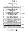
- FIG. 14 is a schematic flowchart of a processing executed by the calculation unit 210 of the image processing apparatus 200 according to the second embodiment. It should be noted that processing steps S201 to S203 are the same as the processing steps S101 to S103 in the first embodiment. Processing steps S204 to S207 will be explained below in contrast with the structure shown in FIG. 13 .
- the area divider 203 divides the intra-cavity image into areas based on an edge in the intra-cavity image (step S204).
- an area division method a technique disclosed in Japanese Patent Application No. 2005-24511 by the same applicant as the present invention is used.
- a gradient direction of a pixel value of each pixel is calculated after a smoothing processing for the purpose of eliminating a noise is performed with respect to the intra-cavity image.
- the gradient direction is a direction in which an intensity difference with a neighborhood pixel is the smallest (a direction of the largest subtractive value).
- FIG. 15 is a view showing an example of scanning from a given pixel of interest T shown by coordinates (x1, y1) to a pixel of extreme value M shown by coordinates (x4, y4).
- FIG. 16 shows an example of a result of performing the area division with respect to the intra-cavity image shown in FIG. 2 by using the area divider 203.
- a method of using a watershed algorithm is also available, for example (reference: Luc Vincent and Pierre Soille, Watersheds in digital spaces: An efficient algorithm based on immersion simulations, Transactions on Pattern Analysis and Machine Intelligence, Vol.13, No.6, pp.583-598, June 1991 ).
- the watershed algorithm is a method of dividing an image so that, when a geography in which pixel value information of the image is expressed by an altitude is filled with water, a boundary is formed between different water hollows.
- the bubble area detector 204 detects a bubble area in the intra-cavity image based on the correlation value calculated by the correlation value calculator 202 and the result of the area division performed by the area divider 203 (step S205).
- the bubble area detector 204 first obtains an average value of correlation values for each area in the area division result. Since a correlation value obtained in an area ascribed to the bubble area is high, the bubble area detector 204 sets a predetermined threshold value and detects as the bubble area an area whose average correlation value is higher than the threshold value.
- FIG. 17 shows the result of the detection by the bubble area detector 204. As seen from FIG. 17 , it is possible to obtain a boundary of the bubble area more accurately with correspondence to a contour edge of a bubble in the intra-cavity image by using the result of the area division performed by the area divider 203.
- the morphologic processor 205 trims an irregularity in shape of the bubble area due to such noises via a morphologic processing (step S206) (reference: Hidefumi KOBATAKE, Mathematic Morphology, CORONA PUBLISHING CO., LTC .).
- a basic of the morphologic processing is two processings i.e., a dilation and an erosion, and an object area is processed by using a basic graphic (reference image) called a structural element in each processing.
- a content of each processing is as follows. Dilation: to output an area covered by a structural element B at a time of parallel translation of an original point of the structural element B in an object area A (see FIG. 18 ). Erosion: to output an area covered by an original point of a structural element B at a time of parallel translation of the structural element B in an object area A (see FIG. 19 ).
- a closing to perform the erosion after the dilation with respect to an object area: see FIG. 20
- an opening to perform the dilation after the erosion with respect to an object area
- a content of each processing is as follows. Closing: to output an area surrounded by a structural element B at a time of translation of the structural element B circumscribing an outside of an object area A (see FIG. 20 ). Opening: to output an area surrounded by a structural element B at a time of translation of the structural element B inscribing an inside of an object area A.
- FIG. 21 shows an example of a result of performing the closing processing with respect to the detection result of the bubble area shown in FIG. 17 by using a circular structural element, and a state of trimmed shapes of parts A and B in FIG. 17 can be seen.
- the morphologic processor 205 performs various morphologic processings depending on an intended use in a way of performing the closing processing for eliminating a foramen in a bubble area; the opening processing for eliminating, except for a bubble area, an area having a minute noise; and the dilation processing for obtaining an area slightly wider than the detected bubble area.
- the calculation unit 210 outputs information of the trimmed bubble area (step S207) and the processing in the image processing apparatus 200 ends.
- the image processing apparatus 200 since a bubble area in an image is detected based on, in addition to the correlation value between the calculated edge intensity and the bubble model, the result of dividing the image into areas based on an edge in the intra-cavity image, more accurate detection, with a correspondence to a contour edge of a bubble, of the bubble area can be realized. Thus, even in a case where the bubble area is present in the vicinity of a diseased site, the image processing apparatus 200 can be made good use of for more properly detecting a diseased site and the like without detecting the diseased site inclusively as the bubble area.
- the processing procedure shown in FIGS. 3 , 14 , and the like performed by each of the edge intensity calculators 101 and 201, the correlation value calculators 102 and 202, the area divider 203, the bubble area detectors 103 and 204, and the morphologic processor 205 may be realized by making an image processing apparatus constructed by a computer such as a personal computer execute prepared image processing program.
- the image processing program can be distributed via a network such as the Internet.
- the image processing program can be recorded in a recording medium such as a hard disk drive, a floppy disk, a compact disk read only memory, a magnetic disk, and a digital versatile disk which can be read by a computer, and executed by being read out from the recording medium by the computer.
- the image processing apparatus and the image processing program according to the present invention are useful for detecting a bubble area present in an image, and specifically suitable for detecting a bubble area present in an image captured in a body cavity.
Abstract
Description
- The present invention relates to an image processing apparatus and an image processing program which detect a bubble area present in an image, and specifically to an image processing apparatus and an image processing program which detect a bubble area present in an image captured in a body cavity.
- Patent Document 1 discloses, as an image processing on an intra-cavity image, a processing of determining an organ based on average color information of an image captured by a capsule endoscope. Specifically, an average value of a red color level and an average value of a blue color level in a pixel of the image are calculated, a discoloration edge position whose amount of change in each color level is not less than a predetermined amount is detected after the calculated values are smoothed in a time-line direction, and a transition of organs is determined in each image among images which are captured by a capsule endoscope and loaded as time-series successive images.
- Patent Document 2 discloses a processing of detecting a diseased site based on color information of each pixel in an image captured by a capsule endoscope. Specifically, each pixel or an averaged pixel value in the image is mapped onto a feature space based on the color information, a cluster for a normal mucous membrane and a cluster for a diseased site are specified after performing clustering in the feature space, and a pixel area classified as the diseased site cluster is detected as a diseased site.
-
- Patent Document 1: Japanese Patent Application Laid-Open No.
2004-337596 - Patent Document 2: Japanese Patent Application Laid-Open No.
2005-192880 - However, since an air bubble (hereinafter simply referred to as "a bubble") is present in a body cavity captured by a capsule endoscope, it often happens that a bubble as well as a mucous membrane are captured in an intra-cavity image. When a bubble is present in an image, an average value, calculated in Patent Document 1, of each color level in the image is not a value which adequately reflects an original color level of the mucous membrane due to an influence of the bubble. Thus, an accuracy of an organ determination deteriorates.
- Besides, a distribution of a pixel of a bubble area is very wide in the feature space based on the color information and overlaps a distribution of a normal mucous membrane and a diseased site. Therefore, when a detection of a diseased site is performed including pixel information of a bubble area, an accuracy of detection deteriorates in Patent Document 2, too.
- In both of the above cases, as long as a bubble area can be detected in an intra-cavity image, a deterioration in accuracy of an organ determination and a diseased site detection can be suppressed by eliminating a pixel corresponding to the bubble area as an invalid pixel from a subsequent processing. However, the current situation is that no effective solution has been found out to deal with the problem of detecting a bubble area in an intra-cavity image so far.
- The present invention has be achieved in view of the foregoing, and an object of the present invention is to provide an image processing apparatus and an image processing program which can detect, in an intra-cavity image, a bubble area that causes a deterioration in accuracy of an organ determination and a diseased site detection.
- To solve the problem described above and to achieve the object, an image processing apparatus according to the present invention includes: an edge intensity calculator which calculates an edge intensity of a pixel in an image; a correlation value calculator which calculates a correlation value between the calculated edge intensity and a bubble model set in advance based on characteristics of a bubble image; and a bubble area detector which detects a bubble area based on the calculated correlation value.
- In the image processing apparatus according to the present invention as set forth in the invention described above, the correlation value calculator calculates correlation values with plural kinds of bubble models, and the bubble area detector detects the bubble area based on the correlation values calculated with the plural kinds of bubble models.
- The image processing apparatus according to the present invention as set forth in the invention described above further includes an area divider which divides the image into areas based on an edge in the image, wherein the bubble area detector detects the bubble area based on the correlation value and a result of the area division.
- In the image processing apparatus according to the present invention as set forth in the invention described above, the bubble model is a template pattern having an intensity structural part of an arc shape.
- In the image processing apparatus according to the present invention as set forth in the invention described above, the bubble model is a template pattern having an intensity structural part of a ring shape.
- In the image processing apparatus according to the present invention as set forth in the invention described above, the bubble model is a template pattern having a high intensity structural part of a ring shape and another high intensity structural part positioned inside the ring shape.
- In the image processing apparatus according to the present invention as set forth in the invention described above, the edge intensity calculator uses a processing of a quadratic differentiation for each direction to calculate the edge intensity.
- The image processing apparatus according to the present invention as set forth in the invention described above further includes a morphologic processor which performs a morphologic processing with respect to a detection result of the bubble area detector.
- In the image processing apparatus according to the present invention as set forth in the invention described above, the image is an image captured in a body cavity.
- An image processing program which makes an image processing apparatus execute a processing of detecting a bubble area in an image according to the present invention, causes the image processing apparatus to execute: an edge intensity calculating procedure which calculates an edge intensity of a pixel in an image; a correlation value calculating procedure which calculates a correlation value between the calculated edge intensity and a bubble model set in advance based on characteristics of a bubble image; and a bubble area detecting procedure which detects a bubble area based on the calculated correlation value.
- In the image processing program according to the present invention as set forth in the invention described above, the correlation value calculating procedure calculates correlation values with plural kinds of bubble models, and the bubble area detecting procedure detects the bubble area based on the correlation values calculated with the plural kinds of bubble models.
- The image processing program according to the present invention as set forth in the invention described above further causes the image processing apparatus to execute an area dividing procedure which divides the image into areas based on an edge in the image, wherein the bubble area detecting procedure detects the bubble area based on the correlation value and a result of the area division.
- In the image processing program according to the present invention as set forth in the invention described above, the bubble model used for calculating the correlation value is a template pattern having an intensity structural part of an arc shape.
- In the image processing program according to the present invention as set forth in the invention described above, the bubble model used for calculating the correlation value is a template pattern having an intensity structural part of a ring shape.
- In the image processing program according to the present invention as set forth in the invention described above, the bubble model used for calculating the correlation value is a template pattern having a high intensity structural part of a ring shape and another high intensity structural part positioned inside the ring shape.
- In the image processing program according to the present invention as set forth in the invention described above, the edge intensity calculating procedure uses a processing of a quadratic differentiation for each direction to calculate the edge intensity.
- The image processing program according to the present invention as set forth in the invention described above further causes the image processing apparatus to execute a morphologic processing procedure which performs a morphologic processing with respect to a detection result of the bubble area detecting procedure.
- In the image processing program according to the present invention as set forth in the invention described above, the image is an image captured in a body cavity.
- The image processing apparatus and the image processing program according to the present invention have an advantageous effect that a bubble area in an image can be detected properly thanks to a configuration in which an edge intensity of a pixel in the image is calculated, a correlation value between the calculated edge intensity and a bubble model which is set in advance based on characteristics of a bubble image is calculated, and a bubble area in the image is detected based on the calculated correlation value.
- Besides, the image processing apparatus and the image processing program according to the present invention have an advantageous effect that more accurate detection, with a correspondence to a contour edge of a bubble, of a bubble area can be realized and be useful for a proper detection of a diseased site and the like thanks to a configuration in which a bubble area in the image is detected based on, in addition to the correlation value between the calculated edge intensity and the bubble model, a result of dividing the image into areas based on an edge in the image.
-
-
FIG. 1 is a schematic block diagram of a structure of an image processing apparatus according to a first embodiment of the present invention; -
FIG. 2 shows an example of an intra-cavity image, including a bubble, captured by a capsule endoscope and the like; -
FIG. 3 is a schematic flowchart of a processing executed by a calculation unit of the image processing apparatus according to the first embodiment; -
FIG. 4 is an explanatory view of directions of a quadratic differentiation calculation in an edge intensity calculation; -
FIG. 5A shows an image example of a bubble part; -
FIG. 5B shows a change in a pixel value of a part along a line A-A' in the image of the bubble part shown inFIG. 5A ; -
FIG. 6 shows an example of a result of the edge intensity calculation; -
FIG. 7 shows an example of a bubble model; -
FIG. 8 shows an example of a basic graphic for creating the bubble model; -
FIG. 9A shows a modification example of the bubble model; -
FIG. 9B shows another modification example of the bubble model; -
FIG. 9C shows still another modification example of the bubble model; -
FIG. 9D shows still another modification example of the bubble model; -
FIG. 10 shows a calculation result of a correlation value between the result example of the edge intensity calculation shown inFIG. 6 and the bubble model shown inFIG. 7 ; -
FIG. 11 shows an example of a calculation result of a correlation value obtained by using plural kinds of bubble models with respect to the result example of the edge intensity calculation shown inFIG. 6 ; -
FIG. 12 shows a detection result of a bubble area based on the correlation value; -
FIG. 13 is a schematic block diagram of a structure of an image processing apparatus according to a second embodiment of the present invention; -
FIG. 14 is a schematic flowchart of a processing executed by a calculation unit of the image processing apparatus according to the second embodiment; -
FIG. 15 is a view showing an example of scanning from a given pixel of interest T shown by coordinates (x1, y1) to a pixel of extreme value M shown by coordinates (x4, y4) ; -
FIG. 16 shows an example of a result of performing an area division with respect to the intra-cavity image shown inFIG. 2 by using an area divider; -
FIG. 17 shows a result of detection by a bubble area detector; -
FIG. 18 is a view showing a dilation processing; -
FIG. 19 is a view showing an erosion processing; -
FIG. 20 is a view showing a closing processing; and -
FIG. 21 shows an example of a result of performing the closing processing with respect to the result of the bubble area detection shown inFIG. 17 by using a circular structural element. -
- 101
- Edge intensity calculator
- 102
- Correlation value calculator
- 103
- Bubble area detector
- 130
- Bubble model
- 131,
- 132 High intensity structural part
- 133,
- 135 Bubble model
- 136a,
- 136b Intensity structural part of arc shape
- 137
- Bubble model
- 138a,
- 138b Intensity structural part of arc shape
- 140
- Bubble model
- 201
- Edge intensity calculator
- 202
- Correlation value calculator
- 203
- Area divider
- 204
- Bubble area detector
- 205
- Morphologic processor
- Best mode(s) for carrying out the invention will be explained with reference to the accompanying drawings. In exemplary embodiments of the present invention described below, an image processing apparatus which detects a bubble area in an intra-cavity image captured by a capsule endoscope and the like will be shown. An intra-cavity image captured by a capsule endoscope is normally a color image having a pixel level (a pixel value) for each of red (R), green (G), and blue (B) colors in each pixel position. However, an intra-cavity image in the embodiment is assumed to be a light-and-shade image, which is converted from such a color image as described above via a known conversion method, like an image expressed by a luminance (via an YCbCr conversion), a luminosity (via an HSI conversion), and the like. As for the conversion, though it is more preferable that image information of a bubble part is less lost, only the G component of the color image may be used to make the light-and-shade image since it is generally known that a change in color hue of an intra-cavity image normally depends most on an absorption spectrum (wavelength) of hemoglobin in blood in a case of not using a pigment, a stain, and the like and that structural information is mostly included in the G component.
-
FIG. 1 is a schematic block diagram of a structure of an image processing apparatus according to a first embodiment.FIG. 2 shows an example of an intra-cavity image, including a bubble, captured by a capsule endoscope and the like. An image processing apparatus 100 according to the first embodiment includes: acalculation unit 110 which is constructed by a microcomputer and has anedge intensity calculator 101 that calculates an edge intensity of a pixel in such an intra-cavity image obtained by imaging an inside of a body cavity as shown inFIG. 2 , acorrelation value calculator 102 that calculates a correlation value between the calculated edge intensity and a bubble model which is set in advance based on characteristics of a bubble image, and abubble area detector 103 that detects a bubble area in the image based on the calculated correlation value; and amemory 120 which stores obtained intra-cavity images and data used by each part. As for a configuration for inputting intra-cavity images as a processing subject into the image processing apparatus 100 and a configuration for processing the result of the bubble area detection after the result is output, no specific limitation is set in the embodiment. -
FIG. 3 is a schematic flowchart of a processing executed by thecalculation unit 110 of the image processing apparatus 100 according to the first embodiment. An image processing procedure will be explained below in contrast with the structure shown inFIG. 1 . - First of all, the
calculation unit 110 obtains an intra-cavity image as a processing subject (step S101). Next, theedge intensity calculator 101 calculates an edge intensity of a pixel of the obtained intra-cavity image (step S102). While there are various methods for calculating the edge intensity, a method of using a processing of a quadratic differentiation for each direction will be explained here.FIG. 4 is an explanatory view of directions of a quadratic differentiation calculation in the edge intensity calculation. First, a quadratic differentiation in a horizontal direction dH, a quadratic differentiation in a vertical direction dV, a quadratic differentiation in a first diagonal direction dD1, and a quadratic differentiation in a second diagonal direction dD2 as shown inFIG. 4 are calculated with respect to a pixel (x, y) of the intra-cavity image by the following equations (1) to (4). -


- It should be noted that P(x, y) is a pixel value of coordinates (x, y) of the intra-cavity image and r is a parameter (integer) showing a pixel range in the quadratic differentiation calculation. When the parameter r is set to a small value, an edge component of high frequency can be calculated, and when the parameter r is set to a large value, an edge component of low frequency can be calculated. Here, the parameter r may be set statically in advance or set dynamically based on an image and the like. Alternatively, the parameter r may be configured to be given from an outside and processed.
- Next, a maximum value on a plus side of the calculation result of the quadratic differentiation for each direction is calculated by the following equation (5) and is treated as an edge intensity E in the pixel.

- By the above described processing, the edge intensity calculation is performed so that an edge intensity is large at a part where a change in a pixel value within the range specified by the parameter r exhibits a convex shape in any one of the horizontal direction, the vertical direction, the first diagonal direction, and the second diagonal direction. A change in a pixel value of a part along a line A-A' in an image of a bubble part shown in
FIG. 5A is shown inFIG. 5B . Based on the characteristics, shown inFIG. 5B , of the bubble image, a convex edge due to a reflection of an illumination for imaging is present in a contour part and an inside of the bubble of the intra-cavity image. Therefore, the processing described above enables obtaining an edge intensity which reflects characteristics of a bubble structure while suppressing a change in a pixel value attributed to other structures in a body cavity. A result example of the edge intensity calculation with respect to the intra-cavity image shown inFIG. 2 is shown inFIG. 6 . - Though the calculation method of the edge intensity of the intra-cavity image via the quadratic differentiation for each direction is shown so far in the first embodiment, the calculation method of the edge intensity may be modified to any other methods depending on an illumination system and an imaging system for illuminating and capturing the intra-cavity image. For example, the calculation can be performed via a spatial filtering by using already known linear differential filters (the Prewitt filter, the Sobel filter, and the like) and quadratic differentiation filters (the Laplacian filter, the Laplacian of Gaussian (LOG) filter, and the like) (reference: Digital Image Processing; Edge Extraction, Computer Graphic Arts Society, p.114).
- Next, the
correlation value calculator 102 calculates a correlation value between the edge intensity calculated by theedge intensity calculator 101 and a bubble model (step S103). Here, the bubble model is set based on characteristics in a bubble image, for example characteristics of having a convex edge of an arc shape present in a contour part and an inside of the bubble due to a reflection of an illumination in a bubble image in an intra-cavity image obtained by an illumination and imaging system of a capsule endoscope, and is a template pattern having a high intensitystructural part 131 of a ring shape and a high intensitystructural part 132 positioned in an inside of the ring shape as shown inFIG. 7 . Though there are a variety of methods of creating the bubble model, the bubble model can be created by creating a basic graphic constituted by a background part of low intensity and a structural part of high intensity as shown inFIG. 8 , and using a smoothing filter (the Gaussian filter and the like) to perform a spatial filtering. Here, a radius R1 and a radius R2 respectively of the high intensitystructural parts structural part 131 are parameters concerning a graphic size in the example of the basic graphic for creating the bubble model shown inFIG. 8 , and may be set statically in advance or set dynamically based on an image and the like. Alternatively, the parameters may be configured to be given from an outside and processed. The same applies to parameters for adjusting a degree of smoothing. - When characteristics of the bubble image in the intra-cavity image to be detected are taken into consideration, it is important for the bubble model to have an intensity structural part at least having an arc shape since an assembly of arc shapes forms the bubble image, and the bubble model is not limited to
such bubble model 130 as shown inFIG. 7 and other bubble models as shown inFIGS. 9A to 9D may be used, for example. Abubble model 133 shown inFIG. 9A has an intensitystructural part 134 of a slightly elliptical and flattened ring shape. Abubble model 135 shown inFIG. 9B has paired intensitystructural parts FIG. 9C has paired intensitystructural parts structural part 139 positioned in an inside of the intensitystructural parts bubble model 140 shown inFIG. 9D has paired intensitystructural parts structural parts structural parts - Here, the correlation between the edge intensity and the bubble model can be calculated by converting both of the edge intensity and the bubble model into a frequency space via the Fourier transform, and performing the inverse Fourier transform of both products as shown in equation (6).

-
FIG. 10 shows a calculation result of a correlation value between the result example of the edge intensity calculation shown inFIG. 6 and the bubble model shown inFIG. 7 . Since the processing performed by thecorrelation value calculator 102 is no more and no less than to calculate a similarity between the edge intensity and the bubble model as a correlation value, other methods of calculating a similarity (SAD: Sum of Absolute Differences, SSD: Sum of Squared Differences, and the like) which are already known as a method for a template matching may be utilized (reference: Digital Image Processing; Similarity, Computer Graphic Arts Society, p.203). - Besides, though the example of obtaining a correlation with one bubble model is shown in the first embodiment, it is possible to deal with a greater variety of bubbles by setting in advance plural kinds of bubble models whose size and shape are different, and obtaining a maximum correlation value for each pixel position after obtaining a correlation value between the edge intensity and each bubble model.
FIG. 11 shows a result example of the correlation value calculation by using plural kinds of bubble models with respect to the result example of the edge intensity calculation shown inFIG. 6 . - Next, the
bubble area detector 103 detects a bubble area in the intra-cavity image based on the correlation value calculated by the correlation value calculator 102 (step S104). A part which exhibits a high correlation with the bubble model showing characteristics of a bubble has high possibility of being ascribed to a bubble area. So, thebubble area detector 103 sets a predetermined threshold value and detects a part having a correlation value higher than the threshold value as a bubble area in the intra-cavity image.FIG. 12 shows a bubble area detection result based on the correlation value, an outline on a colored background being a part detected as a bubble area. - Finally, the
calculation unit 110 outputs information of the bubble area detected by the bubble area detector 103 (step S105) and the processing in the image processing apparatus 100 ends. - In the image processing apparatus 100 according to the first embodiment described above, a bubble area in an intra-cavity image can be detected properly thanks to a configuration in which an edge intensity of a pixel in the intra-cavity image is calculated, a correlation value between the calculated edge intensity and a bubble model which is set in advance based on characteristics of a bubble image, and a bubble area in the intra-cavity image is detected based on the calculated correlation value.
Thus, a deterioration in accuracy of an organ determination and a diseased site detection in the intra-cavity image can be suppressed by eliminating, as an invalid pixel, a pixel of the bubble area in the intra-cavity image captured by a capsule endoscope and the like from a subsequent image processing. -
FIG. 13 is a schematic block diagram of a structure of an image processing apparatus according to a second embodiment of the present invention. An image processing apparatus 200 according to the second embodiment includes: - a
calculation unit 210 which is constructed by a microcomputer and has anedge intensity calculator 201 and - a
correlation value calculator 202 respectively having the same functions as theedge intensity calculator 101 and thecorrelation value calculator 102 in the image processing apparatus 100 according to the first embodiment, anarea divider 203 that divides an intra-cavity image into areas based on an edge in the intra-cavity image, abubble area detector 204 that detects a bubble area in the intra-cavity image based on the correlation value calculated by thecorrelation value calculator 202 and the result of the area division performed by thearea divider 203, and amorphologic processor 205 that performs a morphologic processing with respect to the result of the bubble area detection performed by thebubble area detector 204; and amemory 220 which stores obtained intra-cavity images and - data used by each part. As for a configuration for inputting intra-cavity images as a processing subject into the image processing apparatus 200 and a configuration for processing the result of the bubble area detection after the result is output, no specific limitation is set in the embodiment similarly to the first embodiment.
-
FIG. 14 is a schematic flowchart of a processing executed by thecalculation unit 210 of the image processing apparatus 200 according to the second embodiment. It should be noted that processing steps S201 to S203 are the same as the processing steps S101 to S103 in the first embodiment. Processing steps S204 to S207 will be explained below in contrast with the structure shown inFIG. 13 . - The
area divider 203 divides the intra-cavity image into areas based on an edge in the intra-cavity image (step S204). As an area division method, a technique disclosed in Japanese Patent Application No.2005-24511
FIG. 15 is a view showing an example of scanning from a given pixel of interest T shown by coordinates (x1, y1) to a pixel of extreme value M shown by coordinates (x4, y4).
FIG. 16 shows an example of a result of performing the area division with respect to the intra-cavity image shown inFIG. 2 by using thearea divider 203. - As another area division method, a method of using a watershed algorithm is also available, for example (reference: Luc Vincent and Pierre Soille, Watersheds in digital spaces: An efficient algorithm based on immersion simulations, Transactions on Pattern Analysis and Machine Intelligence, Vol.13, No.6, pp.583-598, June 1991). The watershed algorithm is a method of dividing an image so that, when a geography in which pixel value information of the image is expressed by an altitude is filled with water, a boundary is formed between different water hollows. By applying the watershed algorithm after performing a proper smoothing with respect to the intra-cavity image, a result of area division similar to the result shown in
FIG. 16 can be obtained. - Next, the
bubble area detector 204 detects a bubble area in the intra-cavity image based on the correlation value calculated by thecorrelation value calculator 202 and the result of the area division performed by the area divider 203 (step S205). In fact, thebubble area detector 204 first obtains an average value of correlation values for each area in the area division result. Since a correlation value obtained in an area ascribed to the bubble area is high, thebubble area detector 204 sets a predetermined threshold value and detects as the bubble area an area whose average correlation value is higher than the threshold value.FIG. 17 shows the result of the detection by thebubble area detector 204. As seen fromFIG. 17 , it is possible to obtain a boundary of the bubble area more accurately with correspondence to a contour edge of a bubble in the intra-cavity image by using the result of the area division performed by thearea divider 203. - Here, there is a case where a proper boundary cannot be partially obtained due to an influence of a noise and the like, as shown at parts A and B in
FIG. 17 . Besides, there is a case where a foramen or a minute area which is not a bubble area is present inside the bubble area, like the result of the bubble area detection shown inFIG. 12 in the first embodiment. Then, themorphologic processor 205 trims an irregularity in shape of the bubble area due to such noises via a morphologic processing (step S206) (reference: Hidefumi KOBATAKE, Mathematic Morphology, CORONA PUBLISHING CO., LTC.). A basic of the morphologic processing is two processings i.e., a dilation and an erosion, and an object area is processed by using a basic graphic (reference image) called a structural element in each processing. A content of each processing is as follows.
Dilation: to output an area covered by a structural element B at a time of parallel translation of an original point of the structural element B in an object area A (seeFIG. 18 ).
Erosion: to output an area covered by an original point of a structural element B at a time of parallel translation of the structural element B in an object area A (seeFIG. 19 ). - As a processing formed by a combination of the two processings, a closing (to perform the erosion after the dilation with respect to an object area: see
FIG. 20 ) and an opening (to perform the dilation after the erosion with respect to an object area) are available. Accordingly, a content of each processing is as follows.
Closing: to output an area surrounded by a structural element B at a time of translation of the structural element B circumscribing an outside of an object area A (seeFIG. 20 ).
Opening: to output an area surrounded by a structural element B at a time of translation of the structural element B inscribing an inside of an object area A. - By performing these processings with respect to the detected bubble area, an irregularity in shape can be trimmed.
FIG. 21 shows an example of a result of performing the closing processing with respect to the detection result of the bubble area shown inFIG. 17 by using a circular structural element, and a state of trimmed shapes of parts A and B inFIG. 17 can be seen. Themorphologic processor 205 performs various morphologic processings depending on an intended use in a way of performing the closing processing for eliminating a foramen in a bubble area; the opening processing for eliminating, except for a bubble area, an area having a minute noise; and the dilation processing for obtaining an area slightly wider than the detected bubble area. - Finally, the
calculation unit 210 outputs information of the trimmed bubble area (step S207) and the processing in the image processing apparatus 200 ends. - In the image processing apparatus 200 according to the second embodiment described above, since a bubble area in an image is detected based on, in addition to the correlation value between the calculated edge intensity and the bubble model, the result of dividing the image into areas based on an edge in the intra-cavity image, more accurate detection, with a correspondence to a contour edge of a bubble, of the bubble area can be realized. Thus, even in a case where the bubble area is present in the vicinity of a diseased site, the image processing apparatus 200 can be made good use of for more properly detecting a diseased site and the like without detecting the diseased site inclusively as the bubble area.
- The processing procedure shown in
FIGS. 3 ,14 , and the like performed by each of theedge intensity calculators correlation value calculators area divider 203, thebubble area detectors morphologic processor 205 may be realized by making an image processing apparatus constructed by a computer such as a personal computer execute prepared image processing program. The image processing program can be distributed via a network such as the Internet. Besides, the image processing program can be recorded in a recording medium such as a hard disk drive, a floppy disk, a compact disk read only memory, a magnetic disk, and a digital versatile disk which can be read by a computer, and executed by being read out from the recording medium by the computer. - As described above, the image processing apparatus and the image processing program according to the present invention are useful for detecting a bubble area present in an image, and specifically suitable for detecting a bubble area present in an image captured in a body cavity.
Claims (18)
- An image processing apparatus, comprising:an edge intensity calculator which calculates an edge intensity of a pixel in an image;a correlation value calculator which calculates a correlation value between the calculated edge intensity and a bubble model set in advance based on characteristics of a bubble image; anda bubble area detector which detects a bubble area based on the calculated correlation value.
- The image processing apparatus according to claim 1, wherein
the correlation value calculator calculates correlation values with plural kinds of bubble models, and
the bubble area detector detects the bubble area based on the correlation values calculated with the plural kinds of bubble models. - The image processing apparatus according to claim 1 or 2, further comprising an area divider which divides the image into areas based on an edge in the image, wherein
the bubble area detector detects the bubble area based on the correlation value and a result of the area division. - The image processing apparatus according to any one of claims 1 to 3, wherein the bubble model is a template pattern having an intensity structural part of an arc shape.
- The image processing apparatus according to any one of claims 1 to 3, wherein the bubble model is a template pattern having an intensity structural part of a ring shape.
- The image processing apparatus according to any one of claims 1 to 3, wherein the bubble model is a template pattern having a high intensity structural part of a ring shape and another high intensity structural part positioned inside the ring shape.
- The image processing apparatus according to any one of claims 1 to 6, wherein the edge intensity calculator uses a processing of a quadratic differentiation for each direction to calculate the edge intensity.
- The image processing apparatus according to any one of claims 1 to 7, further comprising a morphologic processor which performs a morphologic processing with respect to a detection result of the bubble area detector.
- The image processing apparatus according to any one of claims 1 to 8, wherein the image is an image captured in a body cavity.
- An image processing program which makes an image processing apparatus execute a processing of detecting a bubble area in an image, the image processing program causing the image processing apparatus to execute:an edge intensity calculating procedure which calculates an edge intensity of a pixel in an image;a correlation value calculating procedure which calculates a correlation value between the calculated edge intensity and a bubble model set in advance based on characteristics of a bubble image; anda bubble area detecting procedure which detects a bubble area based on the calculated correlation value.
- The image processing program according to claim 10, wherein
the correlation value calculating procedure calculates correlation values with plural kinds of bubble models, and
the bubble area detecting procedure detects the bubble area based on the correlation values calculated with the plural kinds of bubble models. - The image processing program according to claim 10 or 11, further causing the image processing apparatus to execute an area dividing procedure which divides the image into areas based on an edge in the image, wherein
the bubble area detecting procedure detects the bubble area based on the correlation value and a result of the area division. - The image processing program according to any one of claims 10 to 12, wherein the bubble model used for calculating the correlation value is a template pattern having an intensity structural part of an arc shape.
- The image processing program according to any one of claims 10 to 12, wherein the bubble model used for calculating the correlation value is a template pattern having an intensity structural part of a ring shape.
- The image processing program according to any one of claims 10 to 12, wherein the bubble model used for calculating the correlation value is a template pattern having a high intensity structural part of a ring shape and another high intensity structural part positioned inside the ring shape.
- The image processing program according to any one of claims 10 to 15, wherein the edge intensity calculating procedure uses a processing of a quadratic differentiation for each direction to calculate the edge intensity.
- The image processing program according to any one of claims 10 to 16, further causing the image processing apparatus to execute a morphologic processing procedure which performs a morphologic processing with respect to a detection result of the bubble area detecting procedure.
- The image processing program according to any one of claims 10 to 17, wherein the image is an image captured in a body cavity.
Applications Claiming Priority (2)
| Application Number | Priority Date | Filing Date | Title |
|---|---|---|---|
| JP2006147316A JP5086563B2 (en) | 2006-05-26 | 2006-05-26 | Image processing apparatus and image processing program |
| PCT/JP2007/057924 WO2007138792A1 (en) | 2006-05-26 | 2007-04-10 | Image processing device and image processing program |
Publications (3)
| Publication Number | Publication Date |
|---|---|
| EP2033567A1 true EP2033567A1 (en) | 2009-03-11 |
| EP2033567A4 EP2033567A4 (en) | 2010-03-10 |
| EP2033567B1 EP2033567B1 (en) | 2015-08-26 |
Family
ID=38778315
Family Applications (1)
| Application Number | Title | Priority Date | Filing Date |
|---|---|---|---|
| EP07741360.7A Expired - Fee Related EP2033567B1 (en) | 2006-05-26 | 2007-04-10 | Image processing device and image processing program |
Country Status (4)
| Country | Link |
|---|---|
| US (1) | US8116531B2 (en) |
| EP (1) | EP2033567B1 (en) |
| JP (1) | JP5086563B2 (en) |
| WO (1) | WO2007138792A1 (en) |
Cited By (6)
| Publication number | Priority date | Publication date | Assignee | Title |
|---|---|---|---|---|
| WO2012110324A1 (en) * | 2011-02-15 | 2012-08-23 | Siemens Aktiengesellschaft | Method and device for examining a hollow organ using a magnet-guided endoscope capsule |
| EP2567651A1 (en) * | 2011-02-01 | 2013-03-13 | Olympus Medical Systems Corp. | Diagnosis assistance apparatus |
| EP2584526A3 (en) * | 2011-10-18 | 2017-05-17 | Olympus Corporation | Image processing device, image processing method, and image processing program |
| WO2020172422A1 (en) * | 2019-02-21 | 2020-08-27 | Medtronic Navigation, Inc. | Method and apparatus for magnetic resonance imaging thermometry |
| US11403760B2 (en) | 2019-02-21 | 2022-08-02 | Medtronic Navigation, Inc. | Method and apparatus for magnetic resonance imaging thermometry |
| US11426229B2 (en) | 2019-02-21 | 2022-08-30 | Medtronic Navigation, Inc. | Method and apparatus for magnetic resonance imaging thermometry |
Families Citing this family (25)
| Publication number | Priority date | Publication date | Assignee | Title |
|---|---|---|---|---|
| US8213698B2 (en) * | 2006-09-19 | 2012-07-03 | Capso Vision Inc. | Systems and methods for capsule camera control |
| JP4859713B2 (en) * | 2007-03-08 | 2012-01-25 | トヨタ自動車株式会社 | Method for measuring the number of non-metallic inclusions |
| JP2010217553A (en) * | 2009-03-17 | 2010-09-30 | Sony Corp | Image generating device and image generating method |
| JP5361530B2 (en) * | 2009-05-20 | 2013-12-04 | キヤノン株式会社 | Image recognition apparatus, imaging apparatus, and image recognition method |
| CN102414720B (en) * | 2010-03-19 | 2015-08-19 | 松下电器(美国)知识产权公司 | Characteristic quantity calculation element, characteristic quantity calculating method |
| CN102724909B (en) | 2010-04-12 | 2015-03-18 | 奥林巴斯医疗株式会社 | Medical image processing apparatus and medical image processing method |
| JP5597049B2 (en) * | 2010-07-07 | 2014-10-01 | オリンパス株式会社 | Image processing apparatus, image processing method, and image processing program |
| JP5757724B2 (en) | 2010-12-10 | 2015-07-29 | オリンパス株式会社 | Image processing apparatus, image processing method, and image processing program |
| JP5576782B2 (en) | 2010-12-16 | 2014-08-20 | オリンパス株式会社 | Image processing apparatus, image processing method, and image processing program |
| JP5526044B2 (en) * | 2011-01-11 | 2014-06-18 | オリンパス株式会社 | Image processing apparatus, image processing method, and image processing program |
| JP6279825B2 (en) * | 2011-05-18 | 2018-02-14 | ソニー株式会社 | Image processing apparatus, image processing method, program, and imaging apparatus |
| KR101248808B1 (en) * | 2011-06-03 | 2013-04-01 | 주식회사 동부하이텍 | Apparatus and method for removing noise on edge area |
| JP5959168B2 (en) | 2011-08-31 | 2016-08-02 | オリンパス株式会社 | Image processing apparatus, operation method of image processing apparatus, and image processing program |
| JP6265588B2 (en) | 2012-06-12 | 2018-01-24 | オリンパス株式会社 | Image processing apparatus, operation method of image processing apparatus, and image processing program |
| JP6242072B2 (en) | 2012-09-27 | 2017-12-06 | オリンパス株式会社 | Image processing apparatus, program, and method of operating image processing apparatus |
| JP5948200B2 (en) | 2012-09-27 | 2016-07-06 | オリンパス株式会社 | Image processing apparatus, program, and image processing method |
| JP6422198B2 (en) | 2012-11-29 | 2018-11-14 | オリンパス株式会社 | Image processing apparatus, image processing method, and image processing program |
| KR20140121711A (en) * | 2013-04-08 | 2014-10-16 | 삼성전자주식회사 | Method of image proccessing, Computer readable storage medium of recording the method and a digital photographing apparatus |
| JP5937286B1 (en) * | 2014-09-29 | 2016-06-22 | オリンパス株式会社 | Image processing apparatus, image processing method, and image processing program |
| US9773154B2 (en) * | 2015-10-09 | 2017-09-26 | Universidad Nacional Autónoma de México | System for the identification and quantification of helminth eggs in environmental samples |
| US10318845B2 (en) * | 2016-04-14 | 2019-06-11 | Research International, Inc. | Coupon reader |
| DE112016006913T5 (en) | 2016-05-27 | 2019-02-14 | Olympus Corporation | Image processing apparatus, operating method of the image processing apparatus, and operation program of the image processing apparatus |
| JP6346721B1 (en) | 2016-11-07 | 2018-06-20 | オリンパス株式会社 | Capsule endoscope, receiving apparatus, capsule endoscope operating method, and capsule endoscope operating program |
| CN114821072B (en) * | 2022-06-08 | 2023-04-18 | 四川大学 | Method, device, equipment and medium for extracting bubbles from dynamic ice image |
| CN115797654B (en) * | 2022-12-09 | 2023-06-23 | 中国民用航空飞行学院 | Bubble bottom parameter identification method in gas-liquid two-phase flow |
Citations (2)
| Publication number | Priority date | Publication date | Assignee | Title |
|---|---|---|---|---|
| WO2002094098A1 (en) * | 2001-05-18 | 2002-11-28 | Polartechnics Limited | Diagnostic feature extraction in dermatological examination |
| WO2005101314A2 (en) * | 2004-04-12 | 2005-10-27 | The General Hospital Corporation | Method and apparatus for processing images in a bowel subtraction system |
Family Cites Families (11)
| Publication number | Priority date | Publication date | Assignee | Title |
|---|---|---|---|---|
| US5566249A (en) * | 1994-09-20 | 1996-10-15 | Neopath, Inc. | Apparatus for detecting bubbles in coverslip adhesive |
| US5835620A (en) * | 1995-12-19 | 1998-11-10 | Neuromedical Systems, Inc. | Boundary mapping system and method |
| FI114414B (en) * | 1999-05-05 | 2004-10-15 | Outokumpu Oy | Method and apparatus for monitoring and analyzing foamed surface |
| JP4493386B2 (en) | 2003-04-25 | 2010-06-30 | オリンパス株式会社 | Image display device, image display method, and image display program |
| JP4254347B2 (en) * | 2003-05-27 | 2009-04-15 | パナソニック電工株式会社 | Method and apparatus for detecting foreign matter in liquid in container |
| JP4254923B2 (en) | 2003-07-03 | 2009-04-15 | 株式会社山武 | Flow rate detection device and flow rate control device |
| JP5129480B2 (en) * | 2003-09-25 | 2013-01-30 | パイエオン インコーポレイテッド | System for performing three-dimensional reconstruction of tubular organ and method for operating blood vessel imaging device |
| US7676257B2 (en) * | 2003-11-25 | 2010-03-09 | General Electric Company | Method and apparatus for segmenting structure in CT angiography |
| JP4652694B2 (en) | 2004-01-08 | 2011-03-16 | オリンパス株式会社 | Image processing method |
| JP4615963B2 (en) * | 2004-10-29 | 2011-01-19 | オリンパス株式会社 | Capsule endoscope device |
| JP4630127B2 (en) * | 2005-05-17 | 2011-02-09 | 株式会社日立製作所 | Ultrasound diagnostic treatment device |
-
2006
- 2006-05-26 JP JP2006147316A patent/JP5086563B2/en active Active
-
2007
- 2007-04-10 WO PCT/JP2007/057924 patent/WO2007138792A1/en active Application Filing
- 2007-04-10 EP EP07741360.7A patent/EP2033567B1/en not_active Expired - Fee Related
-
2008
- 2008-11-25 US US12/277,775 patent/US8116531B2/en active Active
Patent Citations (2)
| Publication number | Priority date | Publication date | Assignee | Title |
|---|---|---|---|---|
| WO2002094098A1 (en) * | 2001-05-18 | 2002-11-28 | Polartechnics Limited | Diagnostic feature extraction in dermatological examination |
| WO2005101314A2 (en) * | 2004-04-12 | 2005-10-27 | The General Hospital Corporation | Method and apparatus for processing images in a bowel subtraction system |
Non-Patent Citations (2)
| Title |
|---|
| E.R: Davies: "Machine Vision: Theory, Algorithms, Practicalities" 2005, Morgan Kaufmann - Elsevier , XP002564427 ISBN: 0122060938 * page 141 - page 143 * * page 232 - page 248 * * |
| See also references of WO2007138792A1 * |
Cited By (10)
| Publication number | Priority date | Publication date | Assignee | Title |
|---|---|---|---|---|
| EP2567651A1 (en) * | 2011-02-01 | 2013-03-13 | Olympus Medical Systems Corp. | Diagnosis assistance apparatus |
| EP2567651A4 (en) * | 2011-02-01 | 2013-04-03 | Olympus Medical Systems Corp | Diagnosis assistance apparatus |
| US8682418B2 (en) | 2011-02-01 | 2014-03-25 | Olympus Medical Systems Corp. | Diagnosis supporting apparatus and control method of diagnosis supporting apparatus |
| WO2012110324A1 (en) * | 2011-02-15 | 2012-08-23 | Siemens Aktiengesellschaft | Method and device for examining a hollow organ using a magnet-guided endoscope capsule |
| EP2584526A3 (en) * | 2011-10-18 | 2017-05-17 | Olympus Corporation | Image processing device, image processing method, and image processing program |
| WO2020172422A1 (en) * | 2019-02-21 | 2020-08-27 | Medtronic Navigation, Inc. | Method and apparatus for magnetic resonance imaging thermometry |
| US11276174B2 (en) | 2019-02-21 | 2022-03-15 | Medtronic Navigation, Inc. | Method and apparatus for magnetic resonance imaging thermometry |
| US11403760B2 (en) | 2019-02-21 | 2022-08-02 | Medtronic Navigation, Inc. | Method and apparatus for magnetic resonance imaging thermometry |
| US11426229B2 (en) | 2019-02-21 | 2022-08-30 | Medtronic Navigation, Inc. | Method and apparatus for magnetic resonance imaging thermometry |
| US11896288B2 (en) | 2019-02-21 | 2024-02-13 | Medtronic Navigation, Inc. | Method and apparatus for magnetic resonance imaging thermometry |
Also Published As
| Publication number | Publication date |
|---|---|
| JP5086563B2 (en) | 2012-11-28 |
| JP2007313119A (en) | 2007-12-06 |
| EP2033567A4 (en) | 2010-03-10 |
| EP2033567B1 (en) | 2015-08-26 |
| US8116531B2 (en) | 2012-02-14 |
| WO2007138792A1 (en) | 2007-12-06 |
| US20090148014A1 (en) | 2009-06-11 |
Similar Documents
| Publication | Publication Date | Title |
|---|---|---|
| EP2033567A1 (en) | Image processing device and image processing program | |
| Kiani et al. | E-shaver: An improved DullRazor® for digitally removing dark and light-colored hairs in dermoscopic images | |
| Yang-Mao et al. | Edge enhancement nucleus and cytoplast contour detector of cervical smear images | |
| EP2466541B1 (en) | Image processing apparatus, image processing method and image processing program | |
| Ahn et al. | Automated saliency-based lesion segmentation in dermoscopic images | |
| JP5926937B2 (en) | Image processing apparatus, image processing method, and image processing program | |
| Luengo-Oroz et al. | Robust iris segmentation on uncalibrated noisy images using mathematical morphology | |
| EP2523164B1 (en) | Image processing apparatus, image processing method, and image processing program | |
| CN108629343B (en) | License plate positioning method and system based on edge detection and improved Harris corner detection | |
| JP5851160B2 (en) | Image processing apparatus, operation method of image processing apparatus, and image processing program | |
| EP2869261B1 (en) | Method for processing image data representing a three-dimensional volume | |
| Zhou et al. | Feature-preserving artifact removal from dermoscopy images | |
| US10540765B2 (en) | Image processing device, image processing method, and computer program product thereon | |
| EP2224401A1 (en) | Computer-aided detection of lesions | |
| CN108601509B (en) | Image processing apparatus, image processing method, and program-recorded medium | |
| CN109255775A (en) | A kind of gastrointestinal epithelial crypts structure based on optical fiber microendoscopic image quantifies analysis method and system automatically | |
| US10856799B2 (en) | Three-dimensional representation of skin structure | |
| Zheng et al. | A review of image segmentation methods for lung nodule detection based on computed tomography images | |
| CN116993764B (en) | Stomach CT intelligent segmentation extraction method | |
| Kim et al. | Tongue diagnosis method for extraction of effective region and classification of tongue coating | |
| CN107529962B (en) | Image processing apparatus, image processing method, and recording medium | |
| CN111260673B (en) | Visceral organ parenchyma segmentation method and device suitable for edge-breaking visceral organ radiography | |
| CN111223116B (en) | Two-stage edge detection method and device for broken edge target | |
| Sengupta et al. | Edge detection in dermascopic images by linear structuring element | |
| Wirth et al. | Combination of color and focus segmentation for medical images with low depth-of-field |
Legal Events
| Date | Code | Title | Description |
|---|---|---|---|
| PUAI | Public reference made under article 153(3) epc to a published international application that has entered the european phase |
Free format text: ORIGINAL CODE: 0009012 |
|
| 17P | Request for examination filed |
Effective date: 20081201 |
|
| AK | Designated contracting states |
Kind code of ref document: A1 Designated state(s): AT BE BG CH CY CZ DE DK EE ES FI FR GB GR HU IE IS IT LI LT LU LV MC MT NL PL PT RO SE SI SK TR |
|
| AX | Request for extension of the european patent |
Extension state: AL BA HR MK RS |
|
| DAX | Request for extension of the european patent (deleted) | ||
| RBV | Designated contracting states (corrected) |
Designated state(s): DE FR GB |
|
| A4 | Supplementary search report drawn up and despatched |
Effective date: 20100208 |
|
| 17Q | First examination report despatched |
Effective date: 20100507 |
|
| GRAP | Despatch of communication of intention to grant a patent |
Free format text: ORIGINAL CODE: EPIDOSNIGR1 |
|
| INTG | Intention to grant announced |
Effective date: 20150324 |
|
| GRAS | Grant fee paid |
Free format text: ORIGINAL CODE: EPIDOSNIGR3 |
|
| GRAA | (expected) grant |
Free format text: ORIGINAL CODE: 0009210 |
|
| AK | Designated contracting states |
Kind code of ref document: B1 Designated state(s): DE FR GB |
|
| REG | Reference to a national code |
Ref country code: GB Ref legal event code: FG4D |
|
| REG | Reference to a national code |
Ref country code: DE Ref legal event code: R096 Ref document number: 602007042784 Country of ref document: DE |
|
| REG | Reference to a national code |
Ref country code: DE Ref legal event code: R097 Ref document number: 602007042784 Country of ref document: DE |
|
| PLBE | No opposition filed within time limit |
Free format text: ORIGINAL CODE: 0009261 |
|
| STAA | Information on the status of an ep patent application or granted ep patent |
Free format text: STATUS: NO OPPOSITION FILED WITHIN TIME LIMIT |
|
| 26N | No opposition filed |
Effective date: 20160530 |
|
| GBPC | Gb: european patent ceased through non-payment of renewal fee |
Effective date: 20160410 |
|
| REG | Reference to a national code |
Ref country code: FR Ref legal event code: ST Effective date: 20161230 |
|
| PG25 | Lapsed in a contracting state [announced via postgrant information from national office to epo] |
Ref country code: FR Free format text: LAPSE BECAUSE OF NON-PAYMENT OF DUE FEES Effective date: 20160502 Ref country code: GB Free format text: LAPSE BECAUSE OF NON-PAYMENT OF DUE FEES Effective date: 20160410 |
|
| PGFP | Annual fee paid to national office [announced via postgrant information from national office to epo] |
Ref country code: DE Payment date: 20170404 Year of fee payment: 11 |
|
| REG | Reference to a national code |
Ref country code: DE Ref legal event code: R119 Ref document number: 602007042784 Country of ref document: DE |
|
| PG25 | Lapsed in a contracting state [announced via postgrant information from national office to epo] |
Ref country code: DE Free format text: LAPSE BECAUSE OF NON-PAYMENT OF DUE FEES Effective date: 20181101 |