EP2033342B1 - Verfahren und system zur leistungsverwaltung in optischen netzwerken - Google Patents
Verfahren und system zur leistungsverwaltung in optischen netzwerken Download PDFInfo
- Publication number
- EP2033342B1 EP2033342B1 EP20070734887 EP07734887A EP2033342B1 EP 2033342 B1 EP2033342 B1 EP 2033342B1 EP 20070734887 EP20070734887 EP 20070734887 EP 07734887 A EP07734887 A EP 07734887A EP 2033342 B1 EP2033342 B1 EP 2033342B1
- Authority
- EP
- European Patent Office
- Prior art keywords
- power
- signal
- carrier
- measurement
- specific
- Prior art date
- Legal status (The legal status is an assumption and is not a legal conclusion. Google has not performed a legal analysis and makes no representation as to the accuracy of the status listed.)
- Not-in-force
Links
- 230000003287 optical effect Effects 0.000 title claims description 103
- 238000000034 method Methods 0.000 title claims description 59
- 238000005259 measurement Methods 0.000 claims description 83
- 239000002131 composite material Substances 0.000 claims description 71
- 238000012544 monitoring process Methods 0.000 claims description 27
- 238000012937 correction Methods 0.000 claims description 14
- 238000004891 communication Methods 0.000 claims description 7
- 238000010183 spectrum analysis Methods 0.000 claims description 5
- 238000001228 spectrum Methods 0.000 claims description 4
- 230000005540 biological transmission Effects 0.000 description 26
- 239000000835 fiber Substances 0.000 description 23
- 230000008569 process Effects 0.000 description 14
- 238000012545 processing Methods 0.000 description 14
- 239000000969 carrier Substances 0.000 description 9
- 230000008859 change Effects 0.000 description 8
- 230000001902 propagating effect Effects 0.000 description 8
- 238000001069 Raman spectroscopy Methods 0.000 description 5
- 230000000694 effects Effects 0.000 description 5
- 238000012806 monitoring device Methods 0.000 description 5
- 230000003321 amplification Effects 0.000 description 4
- 238000012986 modification Methods 0.000 description 4
- 230000004048 modification Effects 0.000 description 4
- 238000003199 nucleic acid amplification method Methods 0.000 description 4
- 238000010079 rubber tapping Methods 0.000 description 4
- 238000001514 detection method Methods 0.000 description 3
- 239000013307 optical fiber Substances 0.000 description 3
- 230000004044 response Effects 0.000 description 3
- 238000012546 transfer Methods 0.000 description 3
- 238000000149 argon plasma sintering Methods 0.000 description 2
- 230000002301 combined effect Effects 0.000 description 2
- 230000002349 favourable effect Effects 0.000 description 2
- 230000035945 sensitivity Effects 0.000 description 2
- 230000003595 spectral effect Effects 0.000 description 2
- 229910052691 Erbium Inorganic materials 0.000 description 1
- 238000005452 bending Methods 0.000 description 1
- 238000006243 chemical reaction Methods 0.000 description 1
- 125000004122 cyclic group Chemical group 0.000 description 1
- 230000001419 dependent effect Effects 0.000 description 1
- 238000009795 derivation Methods 0.000 description 1
- 230000001066 destructive effect Effects 0.000 description 1
- 238000010586 diagram Methods 0.000 description 1
- UYAHIZSMUZPPFV-UHFFFAOYSA-N erbium Chemical compound [Er] UYAHIZSMUZPPFV-UHFFFAOYSA-N 0.000 description 1
- 230000003993 interaction Effects 0.000 description 1
- 239000000203 mixture Substances 0.000 description 1
- 239000004065 semiconductor Substances 0.000 description 1
- 230000000638 stimulation Effects 0.000 description 1
- 230000032258 transport Effects 0.000 description 1
Images


Classifications
-
- H—ELECTRICITY
- H04—ELECTRIC COMMUNICATION TECHNIQUE
- H04B—TRANSMISSION
- H04B10/00—Transmission systems employing electromagnetic waves other than radio-waves, e.g. infrared, visible or ultraviolet light, or employing corpuscular radiation, e.g. quantum communication
- H04B10/80—Optical aspects relating to the use of optical transmission for specific applications, not provided for in groups H04B10/03 - H04B10/70, e.g. optical power feeding or optical transmission through water
- H04B10/85—Protection from unauthorised access, e.g. eavesdrop protection
-
- H—ELECTRICITY
- H04—ELECTRIC COMMUNICATION TECHNIQUE
- H04B—TRANSMISSION
- H04B10/00—Transmission systems employing electromagnetic waves other than radio-waves, e.g. infrared, visible or ultraviolet light, or employing corpuscular radiation, e.g. quantum communication
- H04B10/07—Arrangements for monitoring or testing transmission systems; Arrangements for fault measurement of transmission systems
- H04B10/075—Arrangements for monitoring or testing transmission systems; Arrangements for fault measurement of transmission systems using an in-service signal
- H04B10/077—Arrangements for monitoring or testing transmission systems; Arrangements for fault measurement of transmission systems using an in-service signal using a supervisory or additional signal
- H04B10/0775—Performance monitoring and measurement of transmission parameters
-
- H—ELECTRICITY
- H04—ELECTRIC COMMUNICATION TECHNIQUE
- H04B—TRANSMISSION
- H04B10/00—Transmission systems employing electromagnetic waves other than radio-waves, e.g. infrared, visible or ultraviolet light, or employing corpuscular radiation, e.g. quantum communication
- H04B10/07—Arrangements for monitoring or testing transmission systems; Arrangements for fault measurement of transmission systems
- H04B10/075—Arrangements for monitoring or testing transmission systems; Arrangements for fault measurement of transmission systems using an in-service signal
- H04B10/079—Arrangements for monitoring or testing transmission systems; Arrangements for fault measurement of transmission systems using an in-service signal using measurements of the data signal
- H04B10/0795—Performance monitoring; Measurement of transmission parameters
- H04B10/07955—Monitoring or measuring power
Definitions
- the invention relates to optical networks, and in particular, to a method and system for power management in optical networks, where crosstalk due to optical-power scattering is present.
- low frequency tones are often used for providing both power monitoring and identification of optical channels.
- low-frequency tones each of a frequency between 10 kHz and 1 MHz may be used to modulate the amplitude of individual optical carriers at the edge of the network.
- an optical tap may be used to extract a measured sample of the propagating optical signal comprising wavelength-multiplexed carrier signals.
- the tapped optical signal is processed to detect the individual modulating tones, determine their frequency content, and measure the power levels of individual tones. Tapped-signal processing may be realized using low cost circuitry.
- the document US 2005/0002677 - MCALLISTER discloses methods and apparatus for measuring strength of carriers in an optical communications system employing wavelength division multiplexing.
- Carrier identifiers are applied after data modulation of the carriers, so that the degree of modulation may be reduced in comparison with a system in which carrier identifiers are applied at the source. With this manner, the noise introduced by the carrier identifiers can be reduced.
- the document EP 1564 913 - CORNING Inc discloses a system for detecting optical power loss caused by bending a fiber link, any form of fiber tapping, or natural causes.
- At least one photodetector circuitry coupled to a fiber link at a monitor point detects a change in power ratio between a first wavelength channel and a second wavelength channel to determine potential power loss at any location along the fiber link.
- Optical amplifiers such as the Erbium Doped Fiber Amplifier (EDFA) and the Semiconductor Optical Amplifier (SOA), typically generate cross-talk among wavelength channels of different wavelengths.
- EDFA Erbium Doped Fiber Amplifier
- SOA Semiconductor Optical Amplifier
- the method employs a smart amplifier which includes a conventional optical amplifier and a cross-talk cancellation unit. The method is based on detecting tones at input and output of the smart amplifier, comparing the detected tones, and generating destructive tones having appropriate amplitudes and phases to offset cross-talk components.
- the measured power level of a specific tone, modulating a specific carrier signal may reflect contributions of more than one carrier signal and, hence, may not accurately represent the power of the specific carrier signal.
- the present application is directed towards optical-power control in an optical network employing wavelength-division multiplexed (WDM) optical-fiber links.
- WDM wavelength-division multiplexed
- the present invention provides methods and apparatus for accurate measurement of individual carrier-power levels in an optical transmission system comprising optical channel-routing nodes interconnected by wavelength-division multiplexed (WDM) fiber links.
- the optical network in which the method and apparatus of the present invention is applied uses tone-modulation of optical-carrier signals for tracking end-to-end paths.
- a tone is characterized by a frequency content and power level.
- the frequency content of a tone identifies a carrier signal and the power level of the tone may be used to monitor the power level of the carrier signal it modulates because both the carrier signal and the modulating tone signal experience the same transmission attenuation and similar scattering gain or loss.
- the disclosed method and apparatus are devised to circumvent the effect of optical-power scattering, known as Raman scattering, on the accuracy of carrier-power measurements.
- the present invention provides a method for measuring signal power in a link in a communications network, the link transporting a plurality of carrier signals where each carrier signal is modulated by a respective information signal.
- the method comprises steps of modulating a specific carrier signal with an identifying signal to produce a composite carrier signal where the power of the identifying signal is selected to have a predefined ratio to the power of the specific carrier signal.
- a portion of the light signal comprising the plurality of carrier signals is extracted and analyzed to detect the identifying signal and to obtain a first measurement of power of the identifying signal.
- the power of the composite signal is then modified by a first factor, the identifying signal is detected again, and a second measurement of power of the identifying signal is obtained.
- a first estimate of power of the specific carrier signal is computed as a function of the first measurement, the second measurement, the first factor, and the predefined power ratio.
- An estimate of crosstalk-power component of the identifying signal detected at the monitoring point is determined as the first measurement minus the first estimate.
- An estimate of crosstalk-power component of the specific carrier signal at the monitoring point is determined as the cross-talk power component divided by the predefined power ratio.
- the first factor may be selected as (1- ⁇ ), where 0 ⁇ 1, and the first estimate is determined as (the first measurement - the second measurement)/( ⁇ R), where R is the predefined power ratio.
- the first factor is selected as (1+ ⁇ ), where ⁇ >0, and the first estimate is determined as (the second measurement - the first measurement)/( ⁇ R).
- the method comprises further steps of: modifying the composite carrier signal by a second factor; detecting the identifying signal; obtaining a third measurement of power of the identifying signal; and determining a second estimate of power of the specific carrier signal as a function of the second measurement, the third measurement, the first factor, the second factor, and the predefined power ratio.
- An estimate of crosstalk-power component of the identifying signal detected at the monitoring point is determined as the first measurement minus the second estimate; and an estimate of crosstalk-power component of the specific carrier signal at the monitoring point is determined as the cross-talk power component divided by the predefined power ratio.
- the identifying signal may be selected as a sinusoidal signal spectrally distinct from information signals modulating the carrier signals.
- the identifying signal may comprise time-multiplexed sinusoidal signals which are spectrally distinct from the information signals modulating the carrier signals.
- the first measurement, the second measurement, and the third measurement are obtained by electronic means using either analog spectral analysis or analog-to-digital converters and digital spectral analysis.
- the digital spectral analysis is preferably based on using Fast-Fourier-Transform.
- each other carrier signal may be modulated with a respective identifying signal.
- the method of measuring signal power applies to each carrier signal individually.
- the present invention provides a method for measuring signal power in a link in an optical network, the link transporting a wavelength-multiplexed signal comprising m>1 carrier signals, indexed as 1 to m, where each carrier signal is modulated by a respective information signal and where crosstalk among the modulated carrier signals is present.
- the method comprise a step of amplitude-modulating a specific carrier signal of index j, 1 ⁇ j ⁇ m, and power u j with an identifying signal of power R ⁇ u j , R ⁇ 1, to produce a composite signal prior to transmitting the specific carrier signal.
- Further steps, implemented at a monitoring point along the link include: detecting the identifying signal to obtain a detected identifying signal; obtaining an initial measurement of power ⁇ j of the detected identifying signal; modifying power of the composite signal by a first factor (1+ ⁇ j), where
- > and ⁇ j >-1, being a lower bound of the magnitude of ⁇ j ; obtaining a new measurement ⁇ * j of power of the identifying signal; and determining power of the carrier signal of index j as W j ( ⁇ * j - ⁇ j )/( ⁇ j ⁇ R).
- the value of ⁇ j has a predetermined upper bound â.
- the present invention provides a system for measuring signal power in a link in a communications network, the link transporting m>1 carrier signals modulated by respective information signals, where crosstalk among the carrier signals is present.
- the system comprises: an amplitude modulator for modulating a carrier signal with an identifying signal to produce a composite signal; a detector for detecting the identifying signal from the total optical signal of the link to obtain a detected identifying signal; a signal analyzer for obtaining a power measurement of the detected identifying signal, and a wavelength-selective gain-control device for modifying power of a selected composite signal by a controllable factor.
- the system further comprises a controller communicatively coupled to the wavelength-selective gain-control device and to the signal analyzer.
- the controller sets a first value of the controllable factor; obtains from the signal analyzer a first power measurement of the detected identifying signal corresponding to the first value of the controllable factor; sets a second value of the controllable factor; obtains from the signal analyzer a second power measurement of the detected identifying signal corresponding to the second value of the controllable factor; and determines power of the identifying signal in the composite signal as a function of the first value, the first power measurement, the second value, and the second power measurement.
- the amplitude modulator comprises a power-level selector for selecting a power level of the identifying signal to have a predetermined ratio to a power level of the carrier signal.
- the controller determines power of a carrier-signal component of the selected composite signal as the power of the identifying-signal component divided by the predetermined ratio.
- the wavelength-selective gain-control device may be incorporated in a reconfigurable optical add-drop multiplexer, or a wavelength-selective optical switch.
- the detector may be an analog amplitude detector.
- the signal analyzer preferably comprises: a signal sampler for obtaining samples of the detected identifying signal; an analog-to-digital converter for converting the samples into digital data; and a processor for performing discrete transform of the digital data.
- the present invention provides a method for controlling signal power in an optical network comprising a plurality of optical nodes interconnected by a plurality of links, where each link transports a plurality of composite signals, each composite signal being a carrier signal modulated by a distinctive identifying tone, and where each link has at least one monitoring device with a collocated gain-control device.
- the method comprises steps of cyclically selecting a link according to a predetermined order and sequentially selecting a monitoring device of the link at which the carrier power of each composite signal is estimated.
- the composite signals carried by the link are selected sequentially.
- a first measurement of power of the identifying tone is obtained; the power of the composite signal is modified according to a specific factor; a second measurement of power is obtained; an estimate of power of the identifying tone is determined using the first measurement, the second measurement, and the specific factor; and a correction factor is determined as a ratio of an objective power level to the estimate of power.
- the method further comprises a step of adjusting a power level of the composite signal under consideration at a point in the link preceding the monitoring point according to the correction factor.
- the predetermined order of processing the links may be based on several criteria, such as a number of end-to-end paths traversing each link in the plurality of links.
- the composite signals of each link are preferably arranged in a specific order, such as a descending order of wavelength, for sequential processing.
- An estimate of power of a carrier signal of a composite signal is determined according to a predefined power ratio of the identifying signal to the carrier signal of the composite signal.
- the specific factor may be expressed as (1+ ⁇ ), where -1 ⁇ â, and
- An optical switching node is a device for receiving optical signals from at least two input channels and directing each received optical signal to one of at least two output channels.
- the optical switching node considered herein may take the form of a space switch or a wavelength-channel add-drop multiplexer.
- the input channels may comprise channels arriving from another switching node and sharing an input wavelength-division multiplexed (WDM) link as well as channels from local data sources.
- the output channels may comprise channels directed to another switching node and sharing an output WDM link as well as output channels leading to local data sinks.
- WDM wavelength-division multiplexed
- An optical transmission node is a passive device used for processing signals received from input channels and placing the processed signals to output channels having one-to-one correspondence to the input channels.
- the signalprocessing function may include overall amplification or wavelength-selective gain control.
- Wavelength-tracking unit used in the network of the present invention has a primary function of ensuring proper routing of each carried optical signal.
- the unit may be further provided with a capability to measure optical power.
- Wavelength-selective gain-control device used in the network of the present invention is provided with a capability to apply a predetermined gain (or attenuation) to a selected carrier signal or to any subset of carrier signals.
- Carrier signal The term carrier signal is used to indicate an optical signal of a single frequency (single wavelength).
- An information signal refers to a "payload" signal, modulating a carrier signal.
- a typical information signal is a digital signal of 2.5 or 10 Gigabits per second.
- An identifying signal is a specific signal used to modulate a carrier signal in order to identify the carrier signal as it propagates through switching node to ensure proper routing.
- Signature An identifying signal is often referenced as a "signature" to emphasize its role in tracking (modulated) carrier signals.
- Tone An identifying signal is conveniently devised as a low-frequency sinusoidal signal called "tone".
- tone The term is also used herein to refer to an identifying signal comprising multiple low-frequency sinusoidal signals which may be time-interleaved.
- Tone band A tone comprising multiple-sinusoidal signals, however organized, may occupy a (low) frequency band which may be contiguous or spread.
- Composite carrier signal A carrier signal modulated by both an identifying signal and an information signal is called a "composite carrier signal", or "a composite signal". Modulation by the identifying signal should not interfere with detection of the information signal.
- Wavelength channel A composite carrier signal occupies an optical-frequency band (a wavelength band) within the bandwidth of a fiber link.
- the occupied band is loosely called a "wavelength channel” or a "channel”.
- a link is a transmission medium connecting one switching node to another switching node.
- a WDM link may comprise several wavelength channels.
- a link may comprise a concatenation of fiber-optic spans joined at passive transmission nodes.
- a path comprises a wavelength channel in each of a series of links connecting a first (source) switching node to a second (destination) switching node.
- FIG. 1 illustrates a network 100 in which the present invention may be deployed.
- the network 100 comprises a plurality of optical switching nodes 120 interconnected by optical wavelength-division-multiplexed (WDM) fiber links 125.
- a fiber link 125 exceeding a predetermined length may traverse passive transmission nodes for signal enhancement.
- the passive transmission nodes divide the link into a number of spans as will be illustrated in FIG. 3 .
- a fiber link connecting a first switching node to a second switching node may comprise multiple spans where a first span connects the first switching node to a first passive transmission node. If the fiber link traverses only one passive transmission node, a second span connects the first passive transmission node to the second switching node. Otherwise, the second span connects the first passive transmission node to a second passive transmission node, and a third span connects the second passive transmission node to either the second switching node or to a third passive transmission node, if any, and so on.
- WDM wavelength-di
- An optical switching node 120 may be an edge node directly connected to signal sources and sinks or a core optical node for routing optical signals among edge nodes.
- the network 100 may comprise several tracking units 135 to ensure routing sanity.
- a tracking unit 135 may also be provided with power-measurement devices to ensure appropriate signal power and wavelength-selective gain-control devices to provide power control where needed.
- At least one tracking unit 135 may be placed along a path from one switching node 120 to another.
- a global network controller 160 which may be geographically distributed in the form of well-coordinated control nodes, is communicatively coupled to each of the tracking units 135 either directly through links 162 or through some external network.
- Fig. 1 illustrates two communicatively coupled network controllers 160-1 and 160-2.
- a path from an optical switching node 120 to another may traverse several links 125 where the path includes one wavelength channel in each link.
- An optical node 120 may perform wavelength channel switching, including simple add-drop multiplexing, and may monitor and adjust optical-signal levels.
- each link 125 are individually and uniquely modulated by identifying signals, also called tones, dither tones, or signatures.
- the identifying signals of wavelength channels within a link are distinct.
- An identifying signal associated with a wavelength channel may carry information identifying the channel for tracking purposes.
- An identifying signal may also indicate signal intensity at different points along a WDM link and may be devised to carry other control information.
- each end-to-end path in the network 100 is given a distinct signature and, consequently, a specific signature may appear in two or more links traversed by an end-to-end path.
- the signatures are indicated as s 1 , s 2 ,..., s 804 .
- the required number of distinct signatures is then at least equal to the number of end-to-end paths.
- a signature may not appear in more than one link.
- the number of required signatures is then substantially higher than that of the first scheme.
- Several techniques may be employed to increase the number of available signatures using combinations of identifiers.
- a simple identifier is a low-frequency tone having a frequency within a frequency band or occupying non-contiguous frequency bands carefully selected to meet several criteria.
- the global network control node 160 determines and assigns the individual signatures and distributes relevant information to optical switching nodes 120 of network 100 as well as to any intervening passive optical transmission nodes as illustrated in FIG. 3 .
- the global network controller 160 would have the extra burden of interrelating signatures of channels constituting an end-to-end path.
- a local controller operating in the electronic domain (not illustrated) is associated with each optical switching node and each optical transmission node that participate in the power-monitoring system.
- a network controller 160 may communicate directly with selected local controllers.
- a path from node 120A to node 120D traverses nodes 120B and 120C.
- the path is identified by a signature s 1 which appears in all links 125 connecting optical node 120A to node 120D.
- a path from node 120A to node 120E is identified by a signature s 3 which appears in the three links connecting node 120A to node 120E.
- the channels of each link 125 are monitored to ensure proper routing and proper signal levels.
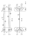
- FIG. 2A illustrates m>1 wavelength channels 215 connecting a first optical node 120X to a second optical node 120Y in a hypothetical arrangement where each of the m channels exclusively occupies a fiber link 215 connecting a port 214 in node 120X to a port 218 in node 120Y.
- m links are needed to connect the first node 120X to the second node 120Y.
- the m channels are centered at wavelengths ⁇ 1 . ⁇ 2 , ..., ⁇ m .
- a channel C j 1 ⁇ j ⁇ m, carries u 1 watts at the sending end (the first node 120X).
- Channel C j delivers W j watts to the second node 120Y.
- the ratio W j /u j is determined by the intrinsic attenuation of link j and any possible amplification along link j.
- the link attenuation (or amplification) is considered time-invariant. There is no interaction among the m channels and, hence, power measurements at the second node may be used directly to adjust the power level at the input of any of the m links.
- spectral multiplexer 224 multiplexes the m channels onto a common link 225. If the attenuation and/or gain of each channel C j , 1 ⁇ j ⁇ m, in the common link 225 is the same as that of link j in the arrangement of FIG. 2A , and if the m wavelengths are spaced to render crosstalk negligible (implying a small number m of channels), then the power carried by channel C j at the second node would be substantially equal to the power W j delivered by link j in the arrangement of FIG. 2A .
- the power- denoted W* j - carried by channel C j at the second node 120 differs from W j by an amount determined by the crosstalk power received from channels of wavelengths shorter than ⁇ j , if any, and crosstalk power transferred to channels of wavelengths greater than ⁇ j , if any.
- a spectral demultiplexer 228 may be used at node 120Y to separate the multiplexed carrier signals and a power-measuring device deployed at the second node 120Y would measure the values W* j , 1 ⁇ j ⁇ m. The contribution of crosstalk to the carrier power W* j of channel C j at the second node 120Y is not directly known.
- a preferred method of measurement uses the identifying signals (also called tones or signatures) described above with reference to FIG. 1 to monitor power levels in any span in any link 125.
- FIG. 3 illustrates a WDM link 125AB in the network of FIG. 1 connecting two optical switching nodes 120A and 120B and traversing two passive transmission nodes 320-1 and 320-2 dividing the link into three spans: a first span (span-1) connecting optical switching node 120A to passive transmission node 320-1; a second span (span-2) connecting the first transmission node 320-1 to the second transmission node 320-2; and the third span (span-3) connecting the second transmission node 320-2 to the second switching node 120B.
- Optical-power control may be applied separately for each of the three spans, to a concatenation of any two spans, or to the entire WDM link 125AB.
- Wavelength tracking units 135 may be provided at all or at a subset of nodes 120A, 320-1, 320-2, and 120B.
- a tracking unit 135 ensures proper routing of wavelength channels by detecting identifying signals of composite carrier signals propagating through a link and comparing with a reference list of expected identifying signals.
- a tracking unit may also include a power detector to determine signal power and a wavelength-selective gain-control device to adjust signal power levels. Signal power levels are adjusted either "permanently" for operational purposes or temporarily for executing the methods of the present invention for accurate power monitoring in the presence of crosstalk as will be detailed below.
- the channel-routing function in network 100 assigns wavelength channels C 1 , C 2 , ..., C m , of carrier wavelengths ⁇ 1 , ⁇ 2 , ..., ⁇ m , to link 125AB.
- the m wavelength channels are expected to be present and at appropriate power levels in each span in link 125AB because each of transmission nodes 320-1 and 320-B is a passive node which may perform signal processing but does not switch a signal to a different path.
- a tracking unit 135-1 provided at a designated output port of switching node 120A verifies that the m channels have been switched properly in switching node 120A and a tracking unit 135-2 provided at transmission node 320-2 verifies that the m channels have maintained appropriate power levels through span-1 and span-2.
- FIG. 4 illustrates a segment of a link 125 in network 100 traversing fiber spans 430, 440, and 460 and including two optical amplifiers 432A and 432B.
- a first wavelength-selective gain-control device 428 receives a WDM optical signal from a fiber link 420 and may adjust the power level of any carrier signal if required.
- Device 428 is illustrated schematically to include a component 422 for isolating a specific (modulated) optical carrier signal, a component 426 for applying a desired gain or attenuation to the specific optical signal, and a combiner 424.
- An optical-signal tapping device 462 is positioned following the second span 440.
- a second wavelength-selective gain-control device 458 is provided in the vicinity of, but preceding, the tapping device 462.
- Components 452, 456, and 454 are similar to components 422, 426, and 424, respectively.
- the device 458 is controlled by a local controller 490 which selects a value of gain (or attenuation) to be applied to a selected wavelength channel.
- Local controller 490 has a control path 492 to the second wavelength-selective gain-control device 458.
- Local controller 490 communicates with the first wavelength-selective gain-control device 428 through a network controller 160.
- the received signal from incoming fiber link 420 comprises a number of carrier signals each carrier signal modulated with an identifying signal in addition to an information signal. Modulating a carrier signal by an identifying signal may take place at a node, preceding fiber link 420, presented in FIG. 4 as node 416. Node 416 may not be directly connected to fiber link 420. Link 420 may, however, carry unmodulated carrier signals in addition to the modulated carrier signals.
- Device 428 may be incorporated in an optical switching node 120, which may be a space switch or an add-drop multiplexer. The output of device 428 comprises m modulated carrier signals propagating through fiber-optic spans 430, 440 and 460 towards some destination.
- the monitoring device 462 taps a portion of the optical signal and the tapped signal is supplied via a (short) link 464 to a low-frequency detector 470.
- the detected low-frequency signal which comprises tone signals of individual carrier signals and other low-frequency components resulting from cross modulation, is supplied to a signal analyzer 480 through an internal path 474.
- the ratio ⁇ of tapped-signal power to the propagating signal power is precisely determined.
- a typical value of the ratio ⁇ is 0.05. It is important to note that any tone-power measurement obtained by any means, analog or digital, is preferably automatically adjusted according to the ratio ⁇ to yield the actual tone power of the corresponding composite signal propagating through the monitored link. Alternatively, the ratio ⁇ may be incorporated in a ratio of tone-signal power in a tapped-signal to actual carrier power.
- a low-frequency signal analyzer 480 may measure the power of any of the tone signals. The measurements are supplied to a local controller 490 through internal path 484, and the local controller 490 communicates the measurements, or a power correction factor based on the measurements, to a network controller 160. A power correction factor is determined by comparing a power measurement with a predetermined objective power level. Controller 160 has a control path (not illustrated) to the first wavelength-selective gain-control device 428, as well as control paths to other monitoring devices as illustrated in FIG. 1 .
- the signal analyzer 480 may be an analog instrument or a digital instrument employing discrete spectral-analysis techniques. If an analog instrument is used, its output is converted to digital format which is directed to the local controller 490.
- any of available software programs for evaluating the discrete Fourier transform of a sampled signal may be used.
- a typical program uses a "Fast-Fourier-Transform" algorithm which lends itself easily to digital realization.
- the derivation of the discrete Fourier transform may be performed in either the signal analyzer 480 or the local controller 490.
- the local controller 490 further implements the methods of the invention to accurately estimate individual carrier power levels at the monitoring point and transmit the results to a respective network controller which instructs the first wavelength-selective gain-control device 428 to adjust carrier-signal power accordingly.
- FIG. 5 illustrates crosstalk power components within a WDM link transporting tone-modulated composite carrier signals.
- the crosstalk among the tone-modulated carrier signals produces composite carrier signals each having an envelope containing the tone-frequencies of all other carriers in addition to the pair-wise sums and differences of the tone frequencies, as illustrated in FIG. 5 which illustrates crosstalk products for a WDM link having six wavelength carriers of wavelengths ⁇ 1 , ⁇ 2 , ⁇ 3 , ⁇ 4 , ⁇ 5 , ⁇ 6 , where ⁇ 1 > ⁇ 2 > ⁇ 3 > ⁇ 4 > ⁇ 5 > ⁇ 6 .
- Each wavelength carrier is modulated with a respective information signal and further amplitude-modulated by a distinctive identifying tone to produce a composite carrier signal.
- each composite carrier signal is said to occupy a "wavelength channel", or simply a "channel”, where each channel corresponds to a wavelength band (an optical-frequency band) centered on a corresponding wavelength (a corresponding optical frequency).
- a channel centered on wavelength ⁇ j is referenced as C j .
- the tone power bears a predetermined ratio to the carrier power.
- the tone signals for the six wavelength channels ⁇ 1 to ⁇ 6 have tone-frequency bands ⁇ 1 , ⁇ 2 , ⁇ 3 , ⁇ 4 , ⁇ 5 , and ⁇ 6 , respectively.
- Other resulting low frequencies are grouped in one column with entries marked 'x'.
- a frequency band ⁇ j , 1 ⁇ j ⁇ 6, may contain a single discrete frequency or a mix of multiple discrete frequencies, and the frequency band is selected to meet certain criteria; for example a frequency band should not overlap the frequency spectrum of information signals modulating the carrier signal.
- the discrete frequencies of different tone-frequency bands may, however, interleave.
- the WDM link may be considered to be ideal, offering unity gain (zero decibels) for each of the composite-signals. This simplification will be reconsidered below.
- the power received at the monitoring point related to wavelength channel C 4 assumes a value of W 4 , where the difference (W* 4 -W 4 ) may be positive, if, due to scattering, channel C 4 receives more power from channels C 5 and C 6 than it imparts to channels C 3 , C 2 , and C 1 , or negative otherwise.
- the tone power of the composite carrier signal received at the monitoring point would be p 4 where the difference (p* 4 -p 4 ) may be positive or negative.
- wavelength channel C 4 imparts to wavelength channels C 3 , C 2 , and C 1 tone power, in frequency band ⁇ 4 , of values ⁇ 4,3 , ⁇ 4,2 , and ⁇ 4,1 , respectively.
- channel C 5 imparts to wavelength channel C 4 tone power, in frequency band ⁇ 5 , of value ⁇ 5,4
- channel C 6 imparts to wavelength channel C 4 tone power, in frequency band ⁇ 6 , of value ⁇ 6,4 .
- the transfer of power from channel C 4 to channels C 1 , C 2 , and C 3 results in amplitude modulation of the carrier signals of channel C 4 , with tones in frequency bands ⁇ 1 , ⁇ 2 , ⁇ 3 , and the power of channel C 4 contains corresponding tone power of values ⁇ 1,4 , ⁇ 2,4 , and ⁇ 3,4 , respectively.
- the transfer of power, from channels C 5 and C 6 to channel C 4 results in amplitude modulation of the carrier signals of channels C 5 , and C 6 with tones in frequency band ⁇ 4 , with corresponding tone power of values ⁇ 4,5 , ⁇ 4,6 , respectively.
- the tone power component p 4 within channel C 4 is indicative of the carrier power W 4 received at the monitoring point.
- the power components identified in row 520 constitute the total power within the wavelength-band (optical-frequency band) occupied by channel C 4 .
- the power components identified in column 530 constitute the total power ⁇ 4 (reference 540) in low-frequency tone band ⁇ 4 as seen by the low-frequency detector 470, and after accounting for instrumentation parameters, such as the proportion of optical-signal power tapped by optical-signal tapping device 462.
- a temporary gain is applied to the signal of channel C j and the corresponding change in the power of channel C j is measured. It is essential, however, that the temporary gain be discriminatory, being applied to either of the components p j or q j , but not both.
- the total power of the composite carrier signal of channel C 4 is multiplied by a predetermined factor (1+ ⁇ ) where -1 ⁇ â, and ⁇ ⁇ a ⁇ .
- the upper bound â is constrained by crosstalk tolerance and the lower bound is based on the sensitivity of detection and measurement instruments.
- FIG. 6 illustrates application of selective gain, in accordance with an embodiment of the present invention, to a composite carrier signal to determine carrier power at a monitoring point along a WDM link.
- the power components identified in row 620 constitute the total power within the wavelength-band (optical-frequency band) occupied by channel C 4 after introducing the temporary gain (1+ ⁇ ). Each power component in row 620 has a value (1+ ⁇ ) times its counterpart in row 520 of FIG. 5 .
- the power components identified in column 630 constitute the total power ⁇ * 4 (reference 640) in low-frequency tone band ⁇ 4 with only the component p 4 being modified by the factor (1+ ⁇ ).
- the WDM link is considered to offer unity gain to each composite carrier signal.
- the gain is determined by the combined effect of intrinsic attenuation, which may be wavelength dependent, and optical-amplifier gain.
- the estimation of carrier-signal power is determined by applying wavelength-selective gain (or attenuation) at the monitoring point and, hence, preceding gain or attenuation is irrelevant.
- FIG. 7 illustrates the combined effect of crosstalk caused by optical-power scattering and crosstalk occurring within optical amplifiers of the passive optical nodes 320 ( FIG. 3 ).
- An optical signal propagating in a link having intermediate optical amplifiers such as Erbium-Doped Fiber Amplifiers (EDFA) suffers from both scattering-induced crosstalk (such as the Raman Stimulation crosstalk) and internal crosstalk within each amplifier.
- EDFA Erbium-Doped Fiber Amplifiers
- a detected tone signal at a monitoring point would be affected by the two crosstalk types.
- the power gain or loss of a tone signal is predominantly caused by the scattering crosstalk.
- Scattering crosstalk may increase (or decrease) the amplitude of the tone with a relative (normalized) increment (or decrement) of ⁇ 1 to result in a corresponding power change proportional to (1 ⁇ 1 ) 2 .
- the crosstalk (of relative magnitude ⁇ 2 ) generated within an EDFA is orthogonal to the scattering crosstalk as illustrated in FIG. 7 .
- the vector diagrams of FIG. 7 illustrate intensity level of a tone signal in the presence of the two types of crosstalk. With an orthogonal relative amplitude increment of ⁇ 2 , (
- the relative power change due to scattering crosstalk is approximately ( ⁇ 2 ⁇ 1 ).
- FIG. 7 The contribution of scattering crosstalk and EDFA crosstalk is illustrated in FIG. 7 where tone-measurement error is plotted as a function of Raman crosstalk levels and EDFA crosstalk levels. It is seen that a contour 740 indicates minor measurement change as EDFA crosstalk varies from -10 decibels to -40 decibels. A contour 760 indicates a significant increase in measurement error as the Raman crosstalk increases from -40 decibels to -10 decibels.
- FIG. 8 illustrates the method, according to the present invention, of determining carrier power, at a monitoring point along a WDM link, of a selected composite carrier signal from among m composite carrier signals sharing a WDM link.
- the method is preferably implemented by local controller 490 ( FIG. 4 ).
- variations of the procedure of FIG. 8 may divide the computational effort between local controller 490 and a respective network controller 160.
- tone power ⁇ j of each channel C j 1 ⁇ j ⁇ m, is measured. Estimation of the individual carrier power for the m channels may be performed in any selected order.
- a channel C j is selected and in step 814 the carrier power ⁇ j of channel C j , as determined in step 810, is compared with a predetermined threshold. If the tone power ⁇ j is found to be below the threshold, the tone power and carrier power of channel C j are considered inadequate for further processing.
- an indication of an indefinite measurement is formed and the processing is directed to step 840.
- step 825 is activated to execute the process of the selective power modification of the present invention and estimation of power in channel C j .
- the result of step 825 is directed to step 840 and local controller 490 reports the computed tone power, carrier power, and crosstalk power to a respective network controller 160.
- Step 840 directs the power-estimation process to step 824 which determines whether to select a subsequent wavelength channel C j (if any) to process a corresponding composite-carrier signal, or to indicate that the process is complete.
- FIG. 9 details a first implementation of step 825 of FIG. 8 .
- a temporary power gain (1+ ⁇ ) is applied to channel C j .
- the method of application of the gain depends on the structure of the detection and monitoring devices used at the monitoring point.
- the value of ⁇ is selected to be below a predetermined upper bound to limit the impact on other wavelength channels.
- a negative value of ⁇ , indicating attenuation, may be used, but should not be close to unity, otherwise subsequent measurements related to channel C j would be unreliable.
- the magnitude of ⁇ regardless whether ⁇ is positive or negative, should be above a certain lower bound in order to produce a measurable effect. The value of depends to a large extent on the sensitivity of the measuring devices.
- step 930 the tone power ⁇ * j in (low) frequency band ⁇ j is measured and the measurement is used in step 940 to compute the power of both the tone and the carrier signals of the composite carrier signal of channel C j .
- FIG. 10 illustrates an alternate implementation of step 825 (referenced as 825A) of FIG. 8 .
- step 1020 a temporary attenuation (1- ⁇ ) is applied to the composite carrier signal of channel C j and in step 1022 the tone power in frequency band ⁇ j is measured to yield a value ⁇ - j .
- step 1024 a subsequent temporary gain (1+ ⁇ ) is applied to the unperturbed composite carrier signal of channel C j and in step 1026 the tone power in frequency band ⁇ j is measured to yield a value ⁇ + j .
- step 1040 the carrier power and crosstalk power of both the tone and the carrier signals of the composite carrier signal of channel C j are computed. Step 1040, to be described below, is quite similar to step 940.
- FIG. 11 details a first implementation of step 940 of FIG. 9 .
- Step 940 is reached from step 930 of FIG. 9 which provides a measurement ⁇ * j of tone power after applying the temporary gain.
- the carrier power W j is determined as p j /R j , R j being the ratio of tone power to carrier power of the composite carrier signal of channel C j at the sending end.
- R j may depend on the corresponding carrier wavelength ⁇ j , where the composite carrier signal of shortest wavelength (being predominantly a donor of scattered power) is given a higher ratio R j , and generally R j >R k for ⁇ j ⁇ k .
- Step 1040 of FIG. 10 is similar to step 940 of FIG. 9 .
- FIG. 12 details a second implementation of step 940 (referenced as 940A) of FIG. 9 .
- a WDM link connecting two optical switching nodes may comprise more than one span where a span connects any two nodes which may be switching nodes, transmission nodes, or one of each.
- the method described above applies to (1) a single span within a WDM link, (2) a path traversing several spans belonging to a single WDM link, (3) a path traversing several spans belonging to concatenated WDM links, or (4) to an end-to-end path from a source optical node 120 to a sink optical node 120.
- the measurement process described in the present application requires an experimental temporary modification of a composite carrier signal over a link of interest.
- the level of power modification is judicially selected so as to avoid undue interference in any other carrier signal.
- Within a single link only one carrier signal is processed at a time as described above. Applying the power-measurement procedure concurrently to any two composite carrier signals propagating in two different links where the two links have a common composite carrier signal may falsify the measurements, or at least reduce the accuracy of the respective carrier-power estimates.
- the accuracy of carrier-power estimation may also be reduced even if the two links do not have a common composite carrier signal. This occurs if at least one carrier signal in the first link and at least one carrier signal in the second link share an intermediate link.
- the network controller 160 may schedule the measurements so that only one carrier signal is considered at a time.
- the network controller 160 may identify groups of links 125 ( FIG. 1 ) each group comprising links 125 that are not directly or indirectly coupled. The links in each group may then be processed concurrently.
- FIG. 13 describes a process executed by a network controller 160 for optical power control of optical-fiber spans across optical network 100.
- the controller 160 maintains a record for each link 125 with detailed information on the wavelength channels and spans of each link 125.
- the controller 160 determines an order of processing the spans of interest in network 100.
- controller 160 selects a link 125 and in step 1322, the wavelength channels of the selected links are identified.
- the controller 160 selects a span within link 125.
- controller 160 determines a specific order of processing the wavelength channels.
- controller 160 receives power measurements and/or an estimated carrier-signal power for a currently considered wavelength channel from a local controller (local controller 490 of FIG. 4 ) to be used for instructing a sending end to adjust power level of the transmitted carried signal if required.
- step 1324 is revisited (from step 1328). Otherwise, step 1328 directs the process to step 1320 to select a new WDM link in network 100.
- the process may execute continuously, thus, when all links 125 have been considered, the first link in the ordered list is revisited.
- the links 125 may be arranged in a preferred order for cyclic processing. For example, the links 125 may be ranked according to the number of end-to-end paths traversing each link; an end-to-end-path being a path traversing links from a source optical node 120 to a sink optical node 120. A link shared by a large number of end-to-end-paths, or a link of high traffic occupancy, may be processed ahead of others.
- the wavelength channels may be considered in step 1326 in a favorable order which takes into account the light-scattering properties.
- a favorable order may be a descending order of wavelengths of the m composite carriers.
- FIG. 14 details step 1326.
- controller 160 identifies a first local controller at the sending end of the selected span and a second local controller (local controller 490, FIG. 4 ) at the receiving end of the span.
- controller 160 selects a wavelength channel.
- controller 160 sends an index j of the selected channel C j to the second local controller and in step 1430 it receives measurements, and/or an estimate of carrier-signal power for channel C j , from the second local controller.
- controller 160 determines a power correction factor for channel C j to be applied at the sending end of the span under consideration. If power correction is to be applied, the index j and the correction factor are sent to the first local controller.
- step 1440 controller 160 receives a response from the first local controller indicating that a correction has been applied to channel C j and step 1436 is executed. If, in step 1434 it is determined that a correction is not needed, step 1436 is executed. If step 1436 determines that all channels of the span under consideration have been considered a subsequent channel from the ordered list is selected in step 1424 and the steps starting with step 1426 and ending in step 1436 are executed again. If step 1436 determines that all wavelength channels have been considered, the process is directed to step 1328 of FIG. 13 .
- FIG. 15 illustrates a process executed by the second local controller (local controller 490 of FIG. 4 ) of the span under consideration for estimating carrier-signal power and determining the correction factor described above.
- the second local controller receives from a network controller 160 an index j of a carrier signal to be measured next (step 1512).
- the power ⁇ j of tone ⁇ j is measured.
- step 1516 if the measured power ⁇ j is found to be insufficient for further processing, step 1520 assigns a default value to p j and other variables to be reported in step 1540.
- step 1516 if the measured power is found to be sufficiently large to permit further processing, the wavelength-selective gain-control device 458 applies a temporary gain to the identified carrier signal and the process described in step 825 of FIG. 8 is executed to compute the carrier-signal power.
- the second local controller maintains a table of objective carrier-signal power for each carrier signal routed through the monitored link or span.
- a ratio ⁇ j of the computed carrier-signal power to a respective objective power is determined (step 1530) and reported (step 1540), together with the carrier-signal power W j to the network controller 160 (step 1560).
- the network controller 160 instructs a controller at the sending end of the monitored link (or span) to adjust power level of the carrier signal.
Landscapes
- Engineering & Computer Science (AREA)
- Physics & Mathematics (AREA)
- Electromagnetism (AREA)
- Computer Networks & Wireless Communication (AREA)
- Signal Processing (AREA)
- Computer Security & Cryptography (AREA)
- Optical Communication System (AREA)
Claims (15)
- Verfahren zur Messung der Signalleistung in einer optischen Verbindung (125, 430, 440, 460) in einem Kommunikationsnetzwerk (100), wobei die besagte optische Verbindung eine Vielzahl von wellenlängengemultiplexten optischen Trägersignalen transportiert, wobei zwischen den Trägersignalen ein Nebensprechen besteht, wobei das Verfahren gekennzeichnet ist durch:Modulieren (416) eines jeden Trägersignals der besagten Vielzahl von wellenlängengemultiplexten optischen Trägersignalen mit einem jeweiligen Kennsignal, welches zu einem jeden besagten Trägersignal ein jeweiliges vordefiniertes Leistungsverhältnis aufweist, um eine jeweilige Vielzahl von zusammengesetzten Signalen zu erzeugen, und an jedem Überwachungspunkt (462) entlang der besagten optischen Verbindung:Auswählen eines spezifischen zusammengesetzten Signals unter der besagten Vielzahl von zusammengesetzten Signalen, wobei das besagte spezifische zusammengesetzte Signal ein durch ein spezifisches Kennsignal moduliertes spezifisches Trägersignal umfasst;Erfassen (470) des besagten spezifischen Kennsignals aus der besagten optischen Verbindung;Gewinnen (480) eines ersten Messwerts (540) der Leistung des spezifischen Kennsignals;Anwenden einer Leistungsverstärkung (458, 920) auf das besagte spezifische zusammengesetzte Signal;Erfassen (470) des besagten spezifischen Kennsignals aus der besagten optischen Verbindung im Anschluss an das besagte Anwenden einer Leistungsverstärkung;Gewinnen (480) eines zweiten Messwerts (640) der Leistung des besagten spezifischen Kennsignals im Anschluss an das besagte Anwenden einer Leistungsverstärkung; undBestimmen (1140, 1180) der Leistung des besagten spezifischen Trägersignals als:
 die besagte Leistungsverstärkung (1+α) entspricht;R ein vordefiniertes Leistungsverhältnis des besagten spezifischen Kennsignals zu dem besagten spezifischen Trägersignal ist; undder Wert von α derart gewählt wird, dass:
die Größe von α niedriger als eine vorbestimmte untere Grenze ist. - Verfahren nach Anspruch 1, weiterhin umfassend das Wählen eines Wertes der besagten vorbestimmten unteren Grenze, welcher ausreicht, um eine messbare Differenz zwischen dem besagten zweiten Messwert und dem besagten ersten Messwert zu ergeben, und eines Wertes der besagten vorbestimmten unteren Grenze in Anhängigkeit von der Nebensprechtoleranz.
- Verfahren nach einem beliebigen der Ansprüche 1 bis 2, wobei das Gewinnen des besagten ersten Messwerts und das Gewinnen des besagten zweiten Messwerts das Anwenden eines schnellen Fourier-Transformationsalgorithmus umfasst.
- Verfahren nach einem beliebigen der Ansprüche 1 bis 3, weiterhin umfassend einen Schritt des aufeinanderfolgenden Auswählens (1422) des besagten spezifischen zusammengesetzten Signals unter zusammengesetzten Signalen, welche der besagten Vielzahl von Trägersignalen entsprechen.
- Verfahren nach einem beliebigen der Verfahren 1 bis 4, weiterhin umfassend einen Schritt des Bestimmens (940A, FIG. 12) eines Verhältnisses p von Nebensprechleistung zu Trägersignalleistung des Trägersignals von Index j als:

wobei π* der besagte zweite Messwert (640) ist und π der besagte erste Messwert (540) ist. - Verfahren nach einem beliebigen der Ansprüche 1 bis 5, weiterhin umfassend einen Schritt des Bestimmens eines Leistungskorrekturfaktors für das besagte spezifische zusammengesetzte Signal als ein Verhältnis eines vordefinierten angestrebten Leistungspegels zu der besagten Leistung des besagten spezifischen Trägersignals.
- System zur Messung der Signalleistung in einer optischen Verbindung (125, 430, 440, 460), welche eine Vielzahl von wellenlängengemultiplexten optischen Trägersignalen transportiert, in einem Kommunikationsnetzwerk (100), wobei zwischen den Trägersignalen ein Nebensprechen besteht, wobei das System gekennzeichnet ist durch:Einen Amplitudenmodulator (416) zum Modulieren eines jeden Trägersignals der besagten Vielzahl von wellenlängengemultiplexten optischen Trägersignalen, mit einem jeweiligen Kennsignal, welches zu einem jeden besagten Trägersignal ein jeweiliges vordefiniertes Leistungsverhältnis aufweist, um eine jeweilige Vielzahl von zusammengesetzten Signalen zu erzeugen;eine wellenlängenselektive Verstärkungsregelungsvorrichtung (458), welche an einem Überwachungspunkt (462) entlang der besagten optischen Verbindung angeordnet und dazu bestimmt ist, eine Leistungsverstärkung auf ein unter der besagten Vielzahl von zusammengesetzten Signalen ausgewähltes zusammengesetztes Signal anzuwenden, wobei das besagte ausgewählte zusammengesetzte Signal ein durch ein spezifisches Kennsignal moduliertes spezifisches Trägersignal umfasst;einen Detektor (470), welcher an die besagte wellenlängenselektive Verstärkungsregelungsvorrichtung (458) gekoppelt ist, zum Erfassen des besagten spezifischen Kennsignals aus der besagten optischen Verbindung;einen Signalanalysator (480), welcher an den besagten Detektor (470) gekoppelt ist;einen Controller (490), welcher kommunikativ an den besagten Signalanalysator (480) und an die besagte wellenlängenselektive Verstärkungsregelungsvorrichtung (458) gekoppelt (492) ist, konfiguriert für:das Gewinnen, von dem besagten Signalanalysator (480), eines ersten Messwerts (540) der Leistung des besagten spezifischen Kennsignals;Anwenden einer Leistungsverstärkung (458, 920) auf das besagte spezifische zusammengesetzte Signal;das Anweisen der besagten Verstärkungsregelungsvorrichtung (458), eine Leistungsverstärkung auf das besagte ausgewählte zusammengesetzte Signal anzuwenden (920);das Gewinnen, von dem besagten Signalanalysator (480), eines zweiten Messwerts (640) der Leistung des besagten spezifischen Kennsignals,welcher der besagten Leistungsverstärkung entspricht; unddas Bestimmen (1140, 1180) der Leistung des besagten spezifischen Trägersignals als:
 die besagte Leistungsverstärkung (1+α) entspricht;R ein vordefiniertes Leistungsverhältnis des besagten spezifischen Kennsignals zu dem besagten spezifischen Trägersignal ist; undder Wert von α derart gewählt wird, dass:
 die Größe von α niedriger als eine vorbestimmte untere Grenze ist.
 - System nach Anspruch 7, wobei der besagte Amplitudenmodulator (416) einen Leistungspegel-Wahlschalter zum Auswählen eines Leistungspegels des besagten spezifischen Kennsignals umfasst.
- System nach einem beliebigen der Ansprüche 7 bis 8, wobei die besagte vorbestimmte obere Grenze von der Nebensprechtoleranz abhängt.
- System nach einem beliebigen der Ansprüche 7 bis 8, wobei die besagte vorbestimmte untere Grenze ausreicht, um eine messbare Differenz zwischen dem besagten zweiten Messwert und dem besagten ersten Messwert zu ergeben.
- System nach einem beliebigen der Ansprüche 7 bis 10, wobei die besagten mehreren wellenlängengemultiplexten optischen Trägersignale weiterhin durch jeweilige Informationssignale moduliert werden und das besagte jeweilige Kennsignal eine Sinuswelle einer Frequenz ist, welche sich von einem Frequenzspektrum eines jeden der besagten jeweiligen Informationssignale unterscheidet.
- System nach einem beliebigen der Ansprüche 7 bis 11, wobei der besagte Detektor ein analoger Amplitudendetektor ist und der besagte Signalanalysator umfasst:einen Signalabtaster zum Gewinnen von Abtastwerten des besagten spezifischen Kennsignals;einen Analog-Digital-Umsetzer zur Umsetzung der besagten Abtastwerte in digitale Daten; undeinen Prozessor zum Durchführen einer diskreten Transformation der besagten digitalen Daten.
- System nach einem beliebigen der Ansprüche 7 bis 12, wobei der besagte Controller (490) konfiguriert ist für:Das Bestimmen eines Leistungskorrekturfaktors für das besagte spezifische zusammengesetzte Signal als ein Verhältnis eines vordefinierten angestrebten Leistungspegels zu der besagten Leistung des besagten spezifischen Trägersignals; unddas Anweisen des das besagte spezifische zusammengesetzte Signal sendenden Endes, den Leistungspegel des besagten spezifischen zusammengesetzten Signals gemäß dem besagten Korrekturfaktor anzupassen.
- System nach einem beliebigen der Ansprüche 7 bis 13, wobei der besagte Signalanalysator (480) für das Durchführen einer digitalen Spektralanalyse konfiguriert ist, um den besagten ersten Messwert (540) der Leistung und den besagten zweiten Messwert (640) der Leistung zu ermitteln.
- System nach einem beliebigen der Ansprüche 7 bis 13, wobei der besagte Signalanalysator (480) für das Anwenden eines schnellen Fourier-Transformationsalgorithmus konfiguriert ist, um den besagten ersten Messwert (540) der Leistung und den besagten zweiten Messwert (640) der Leistung zu ermitteln.
Applications Claiming Priority (3)
| Application Number | Priority Date | Filing Date | Title |
|---|---|---|---|
| US80897506P | 2006-05-30 | 2006-05-30 | |
| US11/754,675 US7715710B2 (en) | 2006-05-30 | 2007-05-29 | Method and system for power management in optical networks |
| PCT/IB2007/001704 WO2007138476A1 (en) | 2006-05-30 | 2007-05-30 | Method and system for power management in optical networks |
Publications (2)
| Publication Number | Publication Date |
|---|---|
| EP2033342A1 EP2033342A1 (de) | 2009-03-11 |
| EP2033342B1 true EP2033342B1 (de) | 2014-02-26 |
Family
ID=38472919
Family Applications (1)
| Application Number | Title | Priority Date | Filing Date |
|---|---|---|---|
| EP20070734887 Not-in-force EP2033342B1 (de) | 2006-05-30 | 2007-05-30 | Verfahren und system zur leistungsverwaltung in optischen netzwerken |
Country Status (4)
| Country | Link |
|---|---|
| US (1) | US7715710B2 (de) |
| EP (1) | EP2033342B1 (de) |
| CN (1) | CN101455005B (de) |
| WO (1) | WO2007138476A1 (de) |
Families Citing this family (32)
| Publication number | Priority date | Publication date | Assignee | Title |
|---|---|---|---|---|
| TWI416193B (zh) * | 2007-12-31 | 2013-11-21 | Hon Hai Prec Ind Co Ltd | 測試鏡頭模組組裝元件之方法 |
| CN101588208B (zh) * | 2008-05-23 | 2012-04-04 | 中兴通讯股份有限公司 | 功率管理方法和装置 |
| US8433192B2 (en) * | 2008-12-08 | 2013-04-30 | Ciena Corporation | Dynamic performance monitoring systems and methods for optical networks |
| US9490894B2 (en) * | 2008-12-08 | 2016-11-08 | Ciena Corporation | Coherent probe and optical service channel systems and methods for optical networks |
| GB2498336A (en) * | 2012-01-04 | 2013-07-17 | Oclaro Technology Plc | Monitoring multiple optical channels |
| WO2013185321A1 (zh) * | 2012-06-14 | 2013-12-19 | 华为技术有限公司 | 信号传输方法、发射机和信号传输系统 |
| US9621261B2 (en) * | 2012-07-26 | 2017-04-11 | Xieon Networks S.A.R.L. | Method and arrangement for channel set up in an optical WDM-network |
| US9363585B2 (en) * | 2014-04-17 | 2016-06-07 | Alcatel Lucent | Operations administration and management service for an optical layer of a communication network |
| US9608723B2 (en) * | 2014-10-20 | 2017-03-28 | Huawei Technologies Co., Ltd. | Carrier-signal power ratio control in direct detection optical systems |
| US9846470B2 (en) | 2015-08-06 | 2017-12-19 | Seagate Technology Llc | Data storage power management |
| CA3006971A1 (en) * | 2015-12-03 | 2017-06-08 | The Arizona Board Of Regents On Behalf Of The University Of Arizona | Fast probing of signal quality in a wdm network |
| US9941991B2 (en) * | 2016-08-29 | 2018-04-10 | Huawei Technologies Co., Ltd. | Method and system for controlling spectral occupancy |
| US10992389B2 (en) | 2018-02-07 | 2021-04-27 | Infinera Corporation | Independently routable digital subcarriers with configurable spacing for optical communication networks |
| US10630416B2 (en) * | 2018-04-11 | 2020-04-21 | Huawei Technologies Co., Ltd. | System and method for optical channel reconfiguration |
| US11368228B2 (en) | 2018-04-13 | 2022-06-21 | Infinera Corporation | Apparatuses and methods for digital subcarrier parameter modifications for optical communication networks |
| US11095389B2 (en) | 2018-07-12 | 2021-08-17 | Infiriera Corporation | Subcarrier based data center network architecture |
| US11095364B2 (en) | 2019-03-04 | 2021-08-17 | Infiriera Corporation | Frequency division multiple access optical subcarriers |
| US11258528B2 (en) | 2019-09-22 | 2022-02-22 | Infinera Corporation | Frequency division multiple access optical subcarriers |
| US11336369B2 (en) | 2019-03-22 | 2022-05-17 | Infinera Corporation | Framework for handling signal integrity using ASE in optical networks |
| US10965439B2 (en) | 2019-04-19 | 2021-03-30 | Infinera Corporation | Synchronization for subcarrier communication |
| US10972184B2 (en) | 2019-05-07 | 2021-04-06 | Infinera Corporation | Bidirectional optical communications |
| US11190291B2 (en) | 2019-05-14 | 2021-11-30 | Infinera Corporation | Out-of-band communication channel for subcarrier-based optical communication systems |
| US11476966B2 (en) | 2019-05-14 | 2022-10-18 | Infinera Corporation | Out-of-band communication channel for subcarrier-based optical communication systems |
| US11095374B2 (en) | 2019-05-14 | 2021-08-17 | Infinera Corporation | Out-of-band communication channel for sub-carrier-based optical communication systems |
| US11239935B2 (en) * | 2019-05-14 | 2022-02-01 | Infinera Corporation | Out-of-band communication channel for subcarrier-based optical communication systems |
| US11489613B2 (en) | 2019-05-14 | 2022-11-01 | Infinera Corporation | Out-of-band communication channel for subcarrier-based optical communication systems |
| US11296812B2 (en) | 2019-05-14 | 2022-04-05 | Infinera Corporation | Out-of-band communication channel for subcarrier-based optical communication systems |
| US11297005B2 (en) | 2019-09-05 | 2022-04-05 | Infiriera Corporation | Dynamically switching queueing schemes for network switches |
| EP4042606A1 (de) | 2019-10-10 | 2022-08-17 | Infinera Corporation | Optischer unterträger-zweiwegschutz und wiederherstellung für optische kommunikationsnetzwerke |
| US12081269B2 (en) | 2019-10-10 | 2024-09-03 | Infinera Corporation | Hub-leaf laser synchronization |
| US11743621B2 (en) | 2019-10-10 | 2023-08-29 | Infinera Corporation | Network switches systems for optical communications networks |
| CN110769335B (zh) * | 2019-11-05 | 2021-08-03 | 苏州大学 | 多纤芯频谱灵活光网络专用保护方法与系统 |
Family Cites Families (9)
| Publication number | Priority date | Publication date | Assignee | Title |
|---|---|---|---|---|
| JP4651231B2 (ja) * | 2001-07-26 | 2011-03-16 | 富士通株式会社 | 光伝送システム |
| CA2358382C (en) | 2001-10-05 | 2008-09-09 | Ping Wai Wan | Channel identification in communications networks |
| US6842561B2 (en) * | 2002-03-29 | 2005-01-11 | Nortel Networks Limited | Optical performance monitoring scheme |
| US7031050B2 (en) | 2002-08-14 | 2006-04-18 | Tropic Networds Inc. | Method and system for precision cross-talk cancellation in optical amplifiers |
| US7248798B2 (en) | 2002-09-30 | 2007-07-24 | Tropic Networks Inc. | Method and system for identification of channels in an optical network |
| US7139486B2 (en) | 2002-12-05 | 2006-11-21 | Tropic Networks Inc. | Method and apparatus for optical add/drop multiplexing in optical networks |
| US7127165B2 (en) | 2003-02-19 | 2006-10-24 | Tropic Networks Inc. | Method and system for compensating for side effects of cross gain modulation in amplified optical networks |
| US20050002677A1 (en) | 2003-07-03 | 2005-01-06 | Polychromix, Inc. | Methods and apparatus for monitoring the strength of carriers in an optical communication system |
| US20050174563A1 (en) * | 2004-02-11 | 2005-08-11 | Evans Alan F. | Active fiber loss monitor and method |
-
2007
- 2007-05-29 US US11/754,675 patent/US7715710B2/en not_active Expired - Fee Related
- 2007-05-30 CN CN2007800198275A patent/CN101455005B/zh not_active Expired - Fee Related
- 2007-05-30 EP EP20070734887 patent/EP2033342B1/de not_active Not-in-force
- 2007-05-30 WO PCT/IB2007/001704 patent/WO2007138476A1/en not_active Ceased
Also Published As
| Publication number | Publication date |
|---|---|
| US20070280687A1 (en) | 2007-12-06 |
| WO2007138476A1 (en) | 2007-12-06 |
| CN101455005B (zh) | 2013-02-20 |
| EP2033342A1 (de) | 2009-03-11 |
| US7715710B2 (en) | 2010-05-11 |
| CN101455005A (zh) | 2009-06-10 |
Similar Documents
| Publication | Publication Date | Title |
|---|---|---|
| EP2033342B1 (de) | Verfahren und system zur leistungsverwaltung in optischen netzwerken | |
| US8014668B2 (en) | Method and system for distributed measurement and compensation of chromatic dispersion in an optical network | |
| CN111279631B (zh) | 利用导频音监测光网络设备的性能 | |
| EP3590210B1 (de) | Systeme und verfahren zur optischen leistungsüberwachung auf multiband-pilottonbasis | |
| US9413455B2 (en) | Apparatus and method for creating calibration coefficient used to monitor optical signal-to-noise ratio | |
| US8655170B2 (en) | OSNR monitor device and OSNR measurement device | |
| CN102714544B (zh) | 确定带内噪声参数的方法和设备及确定光信噪比的方法 | |
| EP0924888A2 (de) | Verfahren und Vorrichtung zum Kanalausgleich in Wellenlängen-Multiplex-Systemen | |
| JP2015106829A (ja) | 光信号品質モニタ装置、光伝送装置、及び、光信号品質モニタ方法 | |
| JP2014064049A (ja) | マルチコアファイバを含む空間分割多重装置及び自己ホモダイン検波方法 | |
| CA2449563C (en) | System and method for measuring power of optical signals carried over a fiber optic link | |
| JP6311443B2 (ja) | 測定装置、測定方法および伝送システム | |
| EP0911994B1 (de) | Überwachung der optischen Signalleistung mit einem Signaturbitmuster in WDM Systemen | |
| JP6497439B2 (ja) | 通信装置、通信方法、及び、通信システム | |
| JP2005502221A (ja) | 光ファイバ・リンクによって伝送された信号においてpmdパラメータを検出し補償するための方法及び装置、並びにこれらを用いた通信システム | |
| EP3417552B1 (de) | Verfahren und vorrichtung zur bereitstellung eines pilottons | |
| US7184672B2 (en) | Analogue maintenance detection | |
| US6549018B1 (en) | Method for measuring the individual crosstalk in wavelength-division multiplex systems and wavelength division multiplex system | |
| EP1517459B1 (de) | Verfahren und Vorrichtung zur Analyse eines über eine Kommunikationsverbindung gesendeten Signals | |
| US8798464B2 (en) | Setting optical power for an optical communications network channel |
Legal Events
| Date | Code | Title | Description |
|---|---|---|---|
| PUAI | Public reference made under article 153(3) epc to a published international application that has entered the european phase |
Free format text: ORIGINAL CODE: 0009012 |
|
| 17P | Request for examination filed |
Effective date: 20081230 |
|
| AK | Designated contracting states |
Kind code of ref document: A1 Designated state(s): AT BE BG CH CY CZ DE DK EE ES FI FR GB GR HU IE IS IT LI LT LU LV MC MT NL PL PT RO SE SI SK TR |
|
| AX | Request for extension of the european patent |
Extension state: AL BA HR MK RS |
|
| 17Q | First examination report despatched |
Effective date: 20100809 |
|
| RAP1 | Party data changed (applicant data changed or rights of an application transferred) |
Owner name: ALCATEL LUCENT |
|
| DAX | Request for extension of the european patent (deleted) | ||
| REG | Reference to a national code |
Ref country code: DE Ref legal event code: R079 Ref document number: 602007035209 Country of ref document: DE Free format text: PREVIOUS MAIN CLASS: H04B0010080000 Ipc: H04B0010077000 |
|
| RIC1 | Information provided on ipc code assigned before grant |
Ipc: H04B 10/077 20130101AFI20130813BHEP Ipc: H04B 10/079 20130101ALI20130813BHEP Ipc: H04B 10/85 20130101ALI20130813BHEP |
|
| 111Z | Information provided on other rights and legal means of execution |
Free format text: AT BE BG CH CY CZ DE DK EE ES FI FR GB GR HU IE IS IT LI LT LU LV MC MT NL PL PT RO SE SI SK TR Effective date: 20130410 |
|
| GRAP | Despatch of communication of intention to grant a patent |
Free format text: ORIGINAL CODE: EPIDOSNIGR1 |
|
| INTG | Intention to grant announced |
Effective date: 20131002 |
|
| GRAS | Grant fee paid |
Free format text: ORIGINAL CODE: EPIDOSNIGR3 |
|
| GRAA | (expected) grant |
Free format text: ORIGINAL CODE: 0009210 |
|
| AK | Designated contracting states |
Kind code of ref document: B1 Designated state(s): AT BE BG CH CY CZ DE DK EE ES FI FR GB GR HU IE IS IT LI LT LU LV MC MT NL PL PT RO SE SI SK TR |
|
| REG | Reference to a national code |
Ref country code: GB Ref legal event code: FG4D |
|
| REG | Reference to a national code |
Ref country code: CH Ref legal event code: EP |
|
| REG | Reference to a national code |
Ref country code: AT Ref legal event code: REF Ref document number: 654107 Country of ref document: AT Kind code of ref document: T Effective date: 20140315 |
|
| REG | Reference to a national code |
Ref country code: IE Ref legal event code: FG4D |
|
| REG | Reference to a national code |
Ref country code: DE Ref legal event code: R096 Ref document number: 602007035209 Country of ref document: DE Effective date: 20140410 |
|
| REG | Reference to a national code |
Ref country code: GB Ref legal event code: 732E Free format text: REGISTERED BETWEEN 20140529 AND 20140604 |
|
| REG | Reference to a national code |
Ref country code: NL Ref legal event code: VDEP Effective date: 20140226 |
|
| REG | Reference to a national code |
Ref country code: AT Ref legal event code: MK05 Ref document number: 654107 Country of ref document: AT Kind code of ref document: T Effective date: 20140226 |
|
| REG | Reference to a national code |
Ref country code: LT Ref legal event code: MG4D |
|
| PG25 | Lapsed in a contracting state [announced via postgrant information from national office to epo] |
Ref country code: IS Free format text: LAPSE BECAUSE OF FAILURE TO SUBMIT A TRANSLATION OF THE DESCRIPTION OR TO PAY THE FEE WITHIN THE PRESCRIBED TIME-LIMIT Effective date: 20140626 Ref country code: LT Free format text: LAPSE BECAUSE OF FAILURE TO SUBMIT A TRANSLATION OF THE DESCRIPTION OR TO PAY THE FEE WITHIN THE PRESCRIBED TIME-LIMIT Effective date: 20140226 |
|
| REG | Reference to a national code |
Ref country code: CH Ref legal event code: PCOW Free format text: NEW ADDRESS: 148/152 ROUTE DE LA REINE, 92100 BOULOGNE-BILLANCOURT (FR) |
|
| REG | Reference to a national code |
Ref country code: FR Ref legal event code: GC Effective date: 20140602 |
|
| RAP2 | Party data changed (patent owner data changed or rights of a patent transferred) |
Owner name: ALCATEL LUCENT |
|
| PG25 | Lapsed in a contracting state [announced via postgrant information from national office to epo] |
Ref country code: SE Free format text: LAPSE BECAUSE OF FAILURE TO SUBMIT A TRANSLATION OF THE DESCRIPTION OR TO PAY THE FEE WITHIN THE PRESCRIBED TIME-LIMIT Effective date: 20140226 Ref country code: CY Free format text: LAPSE BECAUSE OF FAILURE TO SUBMIT A TRANSLATION OF THE DESCRIPTION OR TO PAY THE FEE WITHIN THE PRESCRIBED TIME-LIMIT Effective date: 20140226 Ref country code: FI Free format text: LAPSE BECAUSE OF FAILURE TO SUBMIT A TRANSLATION OF THE DESCRIPTION OR TO PAY THE FEE WITHIN THE PRESCRIBED TIME-LIMIT Effective date: 20140226 Ref country code: NL Free format text: LAPSE BECAUSE OF FAILURE TO SUBMIT A TRANSLATION OF THE DESCRIPTION OR TO PAY THE FEE WITHIN THE PRESCRIBED TIME-LIMIT Effective date: 20140226 Ref country code: AT Free format text: LAPSE BECAUSE OF FAILURE TO SUBMIT A TRANSLATION OF THE DESCRIPTION OR TO PAY THE FEE WITHIN THE PRESCRIBED TIME-LIMIT Effective date: 20140226 Ref country code: PT Free format text: LAPSE BECAUSE OF FAILURE TO SUBMIT A TRANSLATION OF THE DESCRIPTION OR TO PAY THE FEE WITHIN THE PRESCRIBED TIME-LIMIT Effective date: 20140626 |
|
| PG25 | Lapsed in a contracting state [announced via postgrant information from national office to epo] |
Ref country code: BE Free format text: LAPSE BECAUSE OF FAILURE TO SUBMIT A TRANSLATION OF THE DESCRIPTION OR TO PAY THE FEE WITHIN THE PRESCRIBED TIME-LIMIT Effective date: 20140226 Ref country code: LV Free format text: LAPSE BECAUSE OF FAILURE TO SUBMIT A TRANSLATION OF THE DESCRIPTION OR TO PAY THE FEE WITHIN THE PRESCRIBED TIME-LIMIT Effective date: 20140226 |
|
| PG25 | Lapsed in a contracting state [announced via postgrant information from national office to epo] |
Ref country code: DK Free format text: LAPSE BECAUSE OF FAILURE TO SUBMIT A TRANSLATION OF THE DESCRIPTION OR TO PAY THE FEE WITHIN THE PRESCRIBED TIME-LIMIT Effective date: 20140226 Ref country code: EE Free format text: LAPSE BECAUSE OF FAILURE TO SUBMIT A TRANSLATION OF THE DESCRIPTION OR TO PAY THE FEE WITHIN THE PRESCRIBED TIME-LIMIT Effective date: 20140226 Ref country code: CZ Free format text: LAPSE BECAUSE OF FAILURE TO SUBMIT A TRANSLATION OF THE DESCRIPTION OR TO PAY THE FEE WITHIN THE PRESCRIBED TIME-LIMIT Effective date: 20140226 Ref country code: RO Free format text: LAPSE BECAUSE OF FAILURE TO SUBMIT A TRANSLATION OF THE DESCRIPTION OR TO PAY THE FEE WITHIN THE PRESCRIBED TIME-LIMIT Effective date: 20140226 |
|
| REG | Reference to a national code |
Ref country code: DE Ref legal event code: R097 Ref document number: 602007035209 Country of ref document: DE |
|
| PG25 | Lapsed in a contracting state [announced via postgrant information from national office to epo] |
Ref country code: ES Free format text: LAPSE BECAUSE OF FAILURE TO SUBMIT A TRANSLATION OF THE DESCRIPTION OR TO PAY THE FEE WITHIN THE PRESCRIBED TIME-LIMIT Effective date: 20140226 Ref country code: SK Free format text: LAPSE BECAUSE OF FAILURE TO SUBMIT A TRANSLATION OF THE DESCRIPTION OR TO PAY THE FEE WITHIN THE PRESCRIBED TIME-LIMIT Effective date: 20140226 Ref country code: PL Free format text: LAPSE BECAUSE OF FAILURE TO SUBMIT A TRANSLATION OF THE DESCRIPTION OR TO PAY THE FEE WITHIN THE PRESCRIBED TIME-LIMIT Effective date: 20140226 |
|
| REG | Reference to a national code |
Ref country code: FR Ref legal event code: RG Effective date: 20141016 |
|
| PG25 | Lapsed in a contracting state [announced via postgrant information from national office to epo] |
Ref country code: LU Free format text: LAPSE BECAUSE OF FAILURE TO SUBMIT A TRANSLATION OF THE DESCRIPTION OR TO PAY THE FEE WITHIN THE PRESCRIBED TIME-LIMIT Effective date: 20140530 |
|
| REG | Reference to a national code |
Ref country code: CH Ref legal event code: PL |
|
| PLBE | No opposition filed within time limit |
Free format text: ORIGINAL CODE: 0009261 |
|
| STAA | Information on the status of an ep patent application or granted ep patent |
Free format text: STATUS: NO OPPOSITION FILED WITHIN TIME LIMIT |
|
| PG25 | Lapsed in a contracting state [announced via postgrant information from national office to epo] |
Ref country code: LI Free format text: LAPSE BECAUSE OF NON-PAYMENT OF DUE FEES Effective date: 20140531 Ref country code: CH Free format text: LAPSE BECAUSE OF NON-PAYMENT OF DUE FEES Effective date: 20140531 Ref country code: MC Free format text: LAPSE BECAUSE OF FAILURE TO SUBMIT A TRANSLATION OF THE DESCRIPTION OR TO PAY THE FEE WITHIN THE PRESCRIBED TIME-LIMIT Effective date: 20140226 |
|
| 26N | No opposition filed |
Effective date: 20141127 |
|
| REG | Reference to a national code |
Ref country code: IE Ref legal event code: MM4A |
|
| REG | Reference to a national code |
Ref country code: DE Ref legal event code: R097 Ref document number: 602007035209 Country of ref document: DE Effective date: 20141127 |
|
| PG25 | Lapsed in a contracting state [announced via postgrant information from national office to epo] |
Ref country code: IT Free format text: LAPSE BECAUSE OF FAILURE TO SUBMIT A TRANSLATION OF THE DESCRIPTION OR TO PAY THE FEE WITHIN THE PRESCRIBED TIME-LIMIT Effective date: 20140226 |
|
| PG25 | Lapsed in a contracting state [announced via postgrant information from national office to epo] |
Ref country code: IE Free format text: LAPSE BECAUSE OF NON-PAYMENT OF DUE FEES Effective date: 20140530 |
|
| REG | Reference to a national code |
Ref country code: FR Ref legal event code: PLFP Year of fee payment: 9 |
|
| PG25 | Lapsed in a contracting state [announced via postgrant information from national office to epo] |
Ref country code: SI Free format text: LAPSE BECAUSE OF FAILURE TO SUBMIT A TRANSLATION OF THE DESCRIPTION OR TO PAY THE FEE WITHIN THE PRESCRIBED TIME-LIMIT Effective date: 20140226 |
|
| PG25 | Lapsed in a contracting state [announced via postgrant information from national office to epo] |
Ref country code: MT Free format text: LAPSE BECAUSE OF FAILURE TO SUBMIT A TRANSLATION OF THE DESCRIPTION OR TO PAY THE FEE WITHIN THE PRESCRIBED TIME-LIMIT Effective date: 20140226 |
|
| REG | Reference to a national code |
Ref country code: FR Ref legal event code: PLFP Year of fee payment: 10 |
|
| PG25 | Lapsed in a contracting state [announced via postgrant information from national office to epo] |
Ref country code: BG Free format text: LAPSE BECAUSE OF FAILURE TO SUBMIT A TRANSLATION OF THE DESCRIPTION OR TO PAY THE FEE WITHIN THE PRESCRIBED TIME-LIMIT Effective date: 20140226 |
|
| PG25 | Lapsed in a contracting state [announced via postgrant information from national office to epo] |
Ref country code: GR Free format text: LAPSE BECAUSE OF FAILURE TO SUBMIT A TRANSLATION OF THE DESCRIPTION OR TO PAY THE FEE WITHIN THE PRESCRIBED TIME-LIMIT Effective date: 20140527 |
|
| PG25 | Lapsed in a contracting state [announced via postgrant information from national office to epo] |
Ref country code: TR Free format text: LAPSE BECAUSE OF FAILURE TO SUBMIT A TRANSLATION OF THE DESCRIPTION OR TO PAY THE FEE WITHIN THE PRESCRIBED TIME-LIMIT Effective date: 20140226 Ref country code: HU Free format text: LAPSE BECAUSE OF FAILURE TO SUBMIT A TRANSLATION OF THE DESCRIPTION OR TO PAY THE FEE WITHIN THE PRESCRIBED TIME-LIMIT; INVALID AB INITIO Effective date: 20070530 |
|
| REG | Reference to a national code |
Ref country code: FR Ref legal event code: PLFP Year of fee payment: 11 |
|
| REG | Reference to a national code |
Ref country code: FR Ref legal event code: PLFP Year of fee payment: 12 |
|
| PGFP | Annual fee paid to national office [announced via postgrant information from national office to epo] |
Ref country code: DE Payment date: 20180522 Year of fee payment: 12 |
|
| PGFP | Annual fee paid to national office [announced via postgrant information from national office to epo] |
Ref country code: GB Payment date: 20180518 Year of fee payment: 12 |
|
| PGFP | Annual fee paid to national office [announced via postgrant information from national office to epo] |
Ref country code: FR Payment date: 20190410 Year of fee payment: 13 |
|
| REG | Reference to a national code |
Ref country code: DE Ref legal event code: R119 Ref document number: 602007035209 Country of ref document: DE |
|
| GBPC | Gb: european patent ceased through non-payment of renewal fee |
Effective date: 20190530 |
|
| PG25 | Lapsed in a contracting state [announced via postgrant information from national office to epo] |
Ref country code: GB Free format text: LAPSE BECAUSE OF NON-PAYMENT OF DUE FEES Effective date: 20190530 Ref country code: DE Free format text: LAPSE BECAUSE OF NON-PAYMENT OF DUE FEES Effective date: 20191203 |
|
| PG25 | Lapsed in a contracting state [announced via postgrant information from national office to epo] |
Ref country code: FR Free format text: LAPSE BECAUSE OF NON-PAYMENT OF DUE FEES Effective date: 20200531 |