EP2033032B1 - Light-emitting device - Google Patents
Light-emitting device Download PDFInfo
- Publication number
- EP2033032B1 EP2033032B1 EP07722487.1A EP07722487A EP2033032B1 EP 2033032 B1 EP2033032 B1 EP 2033032B1 EP 07722487 A EP07722487 A EP 07722487A EP 2033032 B1 EP2033032 B1 EP 2033032B1
- Authority
- EP
- European Patent Office
- Prior art keywords
- light
- radiation
- optical waveguide
- electrically conductive
- radiation source
- Prior art date
- Legal status (The legal status is an assumption and is not a legal conclusion. Google has not performed a legal analysis and makes no representation as to the accuracy of the status listed.)
- Active
Links
- 230000005855 radiation Effects 0.000 claims description 129
- 230000003287 optical effect Effects 0.000 claims description 61
- 239000000463 material Substances 0.000 claims description 58
- 238000001514 detection method Methods 0.000 claims description 23
- 239000002105 nanoparticle Substances 0.000 claims description 10
- 238000005286 illumination Methods 0.000 claims description 7
- 239000013307 optical fiber Substances 0.000 description 33
- 238000000576 coating method Methods 0.000 description 18
- 238000006243 chemical reaction Methods 0.000 description 17
- 239000011248 coating agent Substances 0.000 description 17
- 238000005253 cladding Methods 0.000 description 12
- 239000011521 glass Substances 0.000 description 10
- 238000001816 cooling Methods 0.000 description 6
- 239000000835 fiber Substances 0.000 description 6
- 239000007787 solid Substances 0.000 description 6
- 239000011575 calcium Substances 0.000 description 5
- 230000008878 coupling Effects 0.000 description 5
- 238000010168 coupling process Methods 0.000 description 5
- 238000005859 coupling reaction Methods 0.000 description 5
- 239000003365 glass fiber Substances 0.000 description 5
- 229910052712 strontium Inorganic materials 0.000 description 5
- 229910052788 barium Inorganic materials 0.000 description 4
- 229910052791 calcium Inorganic materials 0.000 description 4
- 150000001875 compounds Chemical class 0.000 description 4
- 230000000694 effects Effects 0.000 description 4
- 239000000203 mixture Substances 0.000 description 4
- 229910052693 Europium Inorganic materials 0.000 description 3
- 238000000149 argon plasma sintering Methods 0.000 description 3
- -1 barium-magnesium aluminates Chemical class 0.000 description 3
- 239000003990 capacitor Substances 0.000 description 3
- OGPBJKLSAFTDLK-UHFFFAOYSA-N europium atom Chemical compound [Eu] OGPBJKLSAFTDLK-UHFFFAOYSA-N 0.000 description 3
- CIOAGBVUUVVLOB-UHFFFAOYSA-N strontium atom Chemical compound [Sr] CIOAGBVUUVVLOB-UHFFFAOYSA-N 0.000 description 3
- OYPRJOBELJOOCE-UHFFFAOYSA-N Calcium Chemical compound [Ca] OYPRJOBELJOOCE-UHFFFAOYSA-N 0.000 description 2
- OAICVXFJPJFONN-UHFFFAOYSA-N Phosphorus Chemical compound [P] OAICVXFJPJFONN-UHFFFAOYSA-N 0.000 description 2
- DSAJWYNOEDNPEQ-UHFFFAOYSA-N barium atom Chemical compound [Ba] DSAJWYNOEDNPEQ-UHFFFAOYSA-N 0.000 description 2
- 230000008901 benefit Effects 0.000 description 2
- 230000000052 comparative effect Effects 0.000 description 2
- 239000011777 magnesium Substances 0.000 description 2
- 229910052751 metal Inorganic materials 0.000 description 2
- 239000002184 metal Substances 0.000 description 2
- 239000002245 particle Substances 0.000 description 2
- 241001248537 Eurema daira Species 0.000 description 1
- FYYHWMGAXLPEAU-UHFFFAOYSA-N Magnesium Chemical compound [Mg] FYYHWMGAXLPEAU-UHFFFAOYSA-N 0.000 description 1
- 229910004283 SiO 4 Inorganic materials 0.000 description 1
- 229910003668 SrAl Inorganic materials 0.000 description 1
- 239000005084 Strontium aluminate Substances 0.000 description 1
- HCHKCACWOHOZIP-UHFFFAOYSA-N Zinc Chemical compound [Zn] HCHKCACWOHOZIP-UHFFFAOYSA-N 0.000 description 1
- 230000009102 absorption Effects 0.000 description 1
- 238000010521 absorption reaction Methods 0.000 description 1
- 229910001420 alkaline earth metal ion Inorganic materials 0.000 description 1
- 230000008859 change Effects 0.000 description 1
- GTDCAOYDHVNFCP-UHFFFAOYSA-N chloro(trihydroxy)silane Chemical class O[Si](O)(O)Cl GTDCAOYDHVNFCP-UHFFFAOYSA-N 0.000 description 1
- 230000001419 dependent effect Effects 0.000 description 1
- 230000005489 elastic deformation Effects 0.000 description 1
- 230000005611 electricity Effects 0.000 description 1
- 230000005284 excitation Effects 0.000 description 1
- 238000000605 extraction Methods 0.000 description 1
- 230000020169 heat generation Effects 0.000 description 1
- 239000004973 liquid crystal related substance Substances 0.000 description 1
- 229910052749 magnesium Inorganic materials 0.000 description 1
- 239000011572 manganese Substances 0.000 description 1
- WPBNNNQJVZRUHP-UHFFFAOYSA-L manganese(2+);methyl n-[[2-(methoxycarbonylcarbamothioylamino)phenyl]carbamothioyl]carbamate;n-[2-(sulfidocarbothioylamino)ethyl]carbamodithioate Chemical compound [Mn+2].[S-]C(=S)NCCNC([S-])=S.COC(=O)NC(=S)NC1=CC=CC=C1NC(=S)NC(=O)OC WPBNNNQJVZRUHP-UHFFFAOYSA-L 0.000 description 1
- 238000012634 optical imaging Methods 0.000 description 1
- 230000009103 reabsorption Effects 0.000 description 1
- 230000004044 response Effects 0.000 description 1
- 230000035945 sensitivity Effects 0.000 description 1
- 230000005476 size effect Effects 0.000 description 1
- FNWBQFMGIFLWII-UHFFFAOYSA-N strontium aluminate Chemical compound [O-2].[O-2].[O-2].[O-2].[O-2].[Al+3].[Al+3].[Sr+2].[Sr+2] FNWBQFMGIFLWII-UHFFFAOYSA-N 0.000 description 1
- ZEGFMFQPWDMMEP-UHFFFAOYSA-N strontium;sulfide Chemical class [S-2].[Sr+2] ZEGFMFQPWDMMEP-UHFFFAOYSA-N 0.000 description 1
- 239000000725 suspension Substances 0.000 description 1
- 239000011701 zinc Substances 0.000 description 1
- 229910052725 zinc Inorganic materials 0.000 description 1
Images


Classifications
-
- G—PHYSICS
- G02—OPTICS
- G02B—OPTICAL ELEMENTS, SYSTEMS OR APPARATUS
- G02B6/00—Light guides; Structural details of arrangements comprising light guides and other optical elements, e.g. couplings
- G02B6/24—Coupling light guides
- G02B6/42—Coupling light guides with opto-electronic elements
-
- G—PHYSICS
- G02—OPTICS
- G02B—OPTICAL ELEMENTS, SYSTEMS OR APPARATUS
- G02B6/00—Light guides; Structural details of arrangements comprising light guides and other optical elements, e.g. couplings
- G02B6/0001—Light guides; Structural details of arrangements comprising light guides and other optical elements, e.g. couplings specially adapted for lighting devices or systems
- G02B6/0003—Light guides; Structural details of arrangements comprising light guides and other optical elements, e.g. couplings specially adapted for lighting devices or systems the light guides being doped with fluorescent agents
-
- F—MECHANICAL ENGINEERING; LIGHTING; HEATING; WEAPONS; BLASTING
- F21—LIGHTING
- F21S—NON-PORTABLE LIGHTING DEVICES; SYSTEMS THEREOF; VEHICLE LIGHTING DEVICES SPECIALLY ADAPTED FOR VEHICLE EXTERIORS
- F21S41/00—Illuminating devices specially adapted for vehicle exteriors, e.g. headlamps
- F21S41/10—Illuminating devices specially adapted for vehicle exteriors, e.g. headlamps characterised by the light source
- F21S41/12—Illuminating devices specially adapted for vehicle exteriors, e.g. headlamps characterised by the light source characterised by the type of emitted light
- F21S41/13—Ultraviolet light; Infrared light
-
- F—MECHANICAL ENGINEERING; LIGHTING; HEATING; WEAPONS; BLASTING
- F21—LIGHTING
- F21S—NON-PORTABLE LIGHTING DEVICES; SYSTEMS THEREOF; VEHICLE LIGHTING DEVICES SPECIALLY ADAPTED FOR VEHICLE EXTERIORS
- F21S41/00—Illuminating devices specially adapted for vehicle exteriors, e.g. headlamps
- F21S41/10—Illuminating devices specially adapted for vehicle exteriors, e.g. headlamps characterised by the light source
- F21S41/12—Illuminating devices specially adapted for vehicle exteriors, e.g. headlamps characterised by the light source characterised by the type of emitted light
- F21S41/135—Polarised
-
- F—MECHANICAL ENGINEERING; LIGHTING; HEATING; WEAPONS; BLASTING
- F21—LIGHTING
- F21S—NON-PORTABLE LIGHTING DEVICES; SYSTEMS THEREOF; VEHICLE LIGHTING DEVICES SPECIALLY ADAPTED FOR VEHICLE EXTERIORS
- F21S41/00—Illuminating devices specially adapted for vehicle exteriors, e.g. headlamps
- F21S41/10—Illuminating devices specially adapted for vehicle exteriors, e.g. headlamps characterised by the light source
- F21S41/14—Illuminating devices specially adapted for vehicle exteriors, e.g. headlamps characterised by the light source characterised by the type of light source
- F21S41/16—Laser light sources
-
- F—MECHANICAL ENGINEERING; LIGHTING; HEATING; WEAPONS; BLASTING
- F21—LIGHTING
- F21S—NON-PORTABLE LIGHTING DEVICES; SYSTEMS THEREOF; VEHICLE LIGHTING DEVICES SPECIALLY ADAPTED FOR VEHICLE EXTERIORS
- F21S41/00—Illuminating devices specially adapted for vehicle exteriors, e.g. headlamps
- F21S41/10—Illuminating devices specially adapted for vehicle exteriors, e.g. headlamps characterised by the light source
- F21S41/14—Illuminating devices specially adapted for vehicle exteriors, e.g. headlamps characterised by the light source characterised by the type of light source
- F21S41/176—Light sources where the light is generated by photoluminescent material spaced from a primary light generating element
-
- F—MECHANICAL ENGINEERING; LIGHTING; HEATING; WEAPONS; BLASTING
- F21—LIGHTING
- F21S—NON-PORTABLE LIGHTING DEVICES; SYSTEMS THEREOF; VEHICLE LIGHTING DEVICES SPECIALLY ADAPTED FOR VEHICLE EXTERIORS
- F21S41/00—Illuminating devices specially adapted for vehicle exteriors, e.g. headlamps
- F21S41/20—Illuminating devices specially adapted for vehicle exteriors, e.g. headlamps characterised by refractors, transparent cover plates, light guides or filters
- F21S41/24—Light guides
-
- F—MECHANICAL ENGINEERING; LIGHTING; HEATING; WEAPONS; BLASTING
- F21—LIGHTING
- F21S—NON-PORTABLE LIGHTING DEVICES; SYSTEMS THEREOF; VEHICLE LIGHTING DEVICES SPECIALLY ADAPTED FOR VEHICLE EXTERIORS
- F21S45/00—Arrangements within vehicle lighting devices specially adapted for vehicle exteriors, for purposes other than emission or distribution of light
- F21S45/70—Prevention of harmful light leakage
-
- G—PHYSICS
- G01—MEASURING; TESTING
- G01M—TESTING STATIC OR DYNAMIC BALANCE OF MACHINES OR STRUCTURES; TESTING OF STRUCTURES OR APPARATUS, NOT OTHERWISE PROVIDED FOR
- G01M11/00—Testing of optical apparatus; Testing structures by optical methods not otherwise provided for
- G01M11/02—Testing optical properties
- G01M11/06—Testing the alignment of vehicle headlight devices
- G01M11/062—Testing the alignment of vehicle headlight devices using an indicator mounted on the head-light
-
- G—PHYSICS
- G01—MEASURING; TESTING
- G01M—TESTING STATIC OR DYNAMIC BALANCE OF MACHINES OR STRUCTURES; TESTING OF STRUCTURES OR APPARATUS, NOT OTHERWISE PROVIDED FOR
- G01M11/00—Testing of optical apparatus; Testing structures by optical methods not otherwise provided for
- G01M11/08—Testing mechanical properties
- G01M11/088—Testing mechanical properties of optical fibres; Mechanical features associated with the optical testing of optical fibres
-
- G—PHYSICS
- G01—MEASURING; TESTING
- G01M—TESTING STATIC OR DYNAMIC BALANCE OF MACHINES OR STRUCTURES; TESTING OF STRUCTURES OR APPARATUS, NOT OTHERWISE PROVIDED FOR
- G01M11/00—Testing of optical apparatus; Testing structures by optical methods not otherwise provided for
- G01M11/30—Testing of optical devices, constituted by fibre optics or optical waveguides
- G01M11/31—Testing of optical devices, constituted by fibre optics or optical waveguides with a light emitter and a light receiver being disposed at the same side of a fibre or waveguide end-face, e.g. reflectometers
-
- G—PHYSICS
- G01—MEASURING; TESTING
- G01M—TESTING STATIC OR DYNAMIC BALANCE OF MACHINES OR STRUCTURES; TESTING OF STRUCTURES OR APPARATUS, NOT OTHERWISE PROVIDED FOR
- G01M11/00—Testing of optical apparatus; Testing structures by optical methods not otherwise provided for
- G01M11/30—Testing of optical devices, constituted by fibre optics or optical waveguides
- G01M11/33—Testing of optical devices, constituted by fibre optics or optical waveguides with a light emitter being disposed at one fibre or waveguide end-face, and a light receiver at the other end-face
-
- G—PHYSICS
- G02—OPTICS
- G02B—OPTICAL ELEMENTS, SYSTEMS OR APPARATUS
- G02B6/00—Light guides; Structural details of arrangements comprising light guides and other optical elements, e.g. couplings
- G02B6/0001—Light guides; Structural details of arrangements comprising light guides and other optical elements, e.g. couplings specially adapted for lighting devices or systems
-
- G—PHYSICS
- G02—OPTICS
- G02B—OPTICAL ELEMENTS, SYSTEMS OR APPARATUS
- G02B6/00—Light guides; Structural details of arrangements comprising light guides and other optical elements, e.g. couplings
- G02B6/44—Mechanical structures for providing tensile strength and external protection for fibres, e.g. optical transmission cables
- G02B6/4439—Auxiliary devices
- G02B6/4469—Security aspects
-
- G—PHYSICS
- G02—OPTICS
- G02B—OPTICAL ELEMENTS, SYSTEMS OR APPARATUS
- G02B6/00—Light guides; Structural details of arrangements comprising light guides and other optical elements, e.g. couplings
- G02B6/46—Processes or apparatus adapted for installing or repairing optical fibres or optical cables
- G02B6/56—Processes for repairing optical cables
- G02B6/562—Processes for repairing optical cables locatable, e.g. using magnetic means
Definitions
- the invention relates to light-emitting devices with a light guide.
- Light-emitting devices with a light guide for example, from the document WO 2006/038502 A1 known.
- the pamphlets WO 01/40701 A . JP 2005 205195 A . JP 2005 328921 A . JP 61034436 . JP 2003 278444 A . DE 10 2004 010275 B3 and JP 04019601 A describe light emitting devices.
- the device of JP 61034436 in this case also includes a detection device for detecting a damage of a light guide, which is coupled to a light source and a light converter material.
- the object of certain embodiments of the invention is to provide further light-emitting devices with a light guide.
- the efficiency of the light conversion can be increased in this light-emitting device in that the converter material is not arranged in the immediate vicinity of the radiation-emitting radiation source, but is separated by the light guide from the radiation source.
- a reabsorption of the converted light of the longer, second wavelength can be reduced by the radiation source.
- the location of the generation of the visible light from the location of the heat generation, the radiation source is spatially separated, with the result that the operating temperature of the converter material can be lowered, which can increase their reliability.
- Such a spacing of the converter material from the radiation source can also be referred to as "remote phosphor configuration".
- the radiation of the first wavelength can be converted into-preferably visible light-a second wavelength, the second wavelength being greater than the first wavelength of the exciting radiation.
- the radiation-emitting radiation source emits short-wave radiation in the range of 210 to 500 nm, preferably in the range of 210 nm to 420 nm, more preferably in the range of 360 nm to 420 nm or in the more blue range of about 420 nm up to 500 nm.
- the preferably converted-converted light of the second wavelength emitted after the conversion has a longer wavelength than the radiation originally emitted by the radiation source and can be dependent on of this radiation in a wavelength range of 400 to 800 nm.
- the converter material may in particular be a phosphor which can be excited by the radiation emitted by the radiation source, for example to fluorescence.
- oxide-based phosphors such as barium-magnesium aluminates doped with europium, may be used, such as BaMgAl 10 O 17 : Eu 2+ .
- strontium magnesium aluminates which are likewise doped with europium, for example SrMgAl 10 O 17 : Eu 2+ and also chlorapatites with strontium, barium or calcium of the formula (Sr, Ba, Ca) 5 (PO 4 ) 3 Cl: Eu 2+ .
- Green-emitting phosphors are, for example, SrAl 2 O 4 : Eu 2+ .
- Green to green-yellow emitting phosphors are, for example, chloro-silicates of the formula Ca 8 Mg (SiO 4 ) 4 Cl 2 : Eu 2+ , Mn 2+ , which are doped with europium or manganese, and thiogallates of the general formula AGa 2 S 4 : Eu 2+ , Ce 2+ , where A may be selected from calcium, strontium, barium, zinc and magnesium.
- the converter materials or phosphors can also be used in such a way that they emit visible white light upon excitation with short-wave radiation and thus lead to a conversion of the short-wave radiation into visible white light comes.
- the conversion of the radiation of the first wavelength can also result in visible light of the second wavelength, which does not leave a white light impression in the viewer, but z. B. yellow, green red or any other color.
- the optical fiber may comprise fibers containing a material selected from glass and plastic.
- the light guide may also include fiber optic cables or light guide rods.
- UV light are particularly well suited optical fiber based on glass.
- the optical fiber may be constructed like a fiber, wherein a cross section through such a fiber shows a high refractive index core region surrounded by a cladding region having a lower refractive index than the core region.
- the core region is capable of coupled modes of light and short-wave radiation z. B. by means of interference and reflection.
- a plurality of optical fibers may also be present, which are combined, for example, to form an optical fiber bundle, each individual optical fiber separately being emitted by the radiation source
- Radiation first wavelength after coupling to the converter material can transport.
- a further embodiment of a light-emitting device according to the invention may also comprise a plurality of radiation sources, it being possible, for example, for a radiation source to be present for each one light guide. The radiation of the first wavelength emitted by these radiation sources can then be bundled by means of the light guides into, for example, an optical fiber bundle and converted into the light of the second, longer wavelength after the radiation has been transported through the optical fiber bundle by means of the converter material.
- the radiation of the various radiation sources which is coupled into different optical fibers is converted by means of different converter materials in visible light of different second wavelength, resulting in a mixture of this visible light of different wavelength then a homogeneous white light impression for the viewer. So z.
- the optical components and / or transparent bodies described below may be used for such a mixture.
- an optical component can be present which interacts with the converted light or with the radiation of the first wavelength emerging from the light guide.
- This optical component for example, with the converted light or with the exiting from the light guide radiation of the first wavelength, z. B. short-wave radiation by means of scattering, refraction, reflection, deflection or diffraction interact.
- the optical component may, for example, comprise a lens which may, for example, focus the converted light.
- the converter material can be arranged at one end of the optical waveguide and this end can be arranged in the focal point of the optical component.
- the longer-wavelength visible light generated by the converter material is then radiated in parallel through the optical component, for example, a lens, so that parallel directed light emission of the converted light in a particular radiation direction is possible.
- the end of the optical waveguide with the converter material is arranged outside the focal point of the optical component and can then serve, for example, for defocusing the visible light produced by means of conversion.
- z. B. the radiation of a Punklichtario, which is due to the conversion of z. B. short-wave radiation (eg., UV radiation) to visible radiation at one end of a glass fiber can arise as a light guide, expand with the result that then a larger area can be illuminated by the point light source.
- the radiation source may comprise, for example, a short-wave radiation source, in particular a UV laser diode, for example an N-based laser diode such as an InGaN laser diode.
- a short-wave radiation source in particular a UV laser diode, for example an N-based laser diode such as an InGaN laser diode.
- UV laser diodes are particularly well suited to emit a directional UV radiation that can be well coupled into an optical fiber.
- light-emitting devices can achieve a particularly good optical imaging quality by realizing a bright, point-like light source by virtue of the radiation of the first wavelength (eg UV radiation) of the radiation source passing through an optical waveguide which is, for example, a glass fiber. is transported.
- Particularly good point light sources can be achieved by using UV lasers with optical fibers and converter materials. Point light sources have a narrow spatial extent, with a large contrast between illuminated and non-illuminated areas.
- the radiation source can be connected to dissipate the heat loss, for example, with a heat sink.
- the radiation source can be directly connected to the heat sink, or be in thermal contact with it.
- the converter material may comprise nanoparticles.
- the advantage of nanoparticles can be that they reduce the light scattering and thus the luminous intensity of the visible light emitted by the converter material becomes more uniform.
- the nanoparticles have particle diameters which at some nanometers, for example between 2 to 50 nm, more preferably between 2 nm to 10 nm, since such small nanoparticles reduce light scattering of the converted visible light particularly well.
- the particle diameter, the wavelength of the converted light z. B. due to the quantum size effect. For example, smaller diameter nanoparticles produce converted light of shorter wavelength compared to larger diameter nanoparticles.
- a detection device is additionally present which can detect and thus indicate damage to the light guide.
- the detection device which can detect damage to the light guide, also controls a power supply (current and / or voltage supply) for the preferably short-wave radiation emitting radiation source and can thus turn off the power supply in case of damage to the light guide, with the result that the potentially dangerous emission of short-wave radiation, eg. B. UV radiation from the damaged optical fiber is interrupted.
- a power supply current and / or voltage supply
- the detection device comprises a first detector for detecting the converted light, wherein then the detection of the converted light indicates the operability of the light guide.
- the light generated by the converter material of the second, longer, z. B. visible wavelength of the converter material are emitted isotropically in all directions. Since the detection device is present at one end of the light guide and the conversion material is present at the other end of the light guide, there is a coupling of converted light into the light guide, this converted light through the light guide back to the first detector at the other end of the optical fiber Optical fiber is transported. Detection of converted light by the first detector indicates that the light guide is functioning and intact.
- the first detector or the detection device can switch off a power supply of the radiation source.
- the detection device may be part of a circuit arrangement, which supplies the power supply of the radiation source with electricity and which interrupts this circuit in the absence of detection of the converted light.
- the radiation source for example, a UV laser diode with low power is turned on when turning on the light-emitting device and then deactivated when starting the laser, the original power switch for the laser
- a control circuit in which the detection device forms a component takes over the control of the laser.
- the laser is then operated only in response to a successful detection of the converted light by the detection device and can be switched off immediately when no longer existing detection of the converted light.
- the first detector is coupled to one end of a light guide in a light-conducting manner, wherein the converter material is then arranged at the other end of this light guide.
- This light guide may be part of a larger optical fiber network, such as a fiber optic bundle.
- the other optical fibers of this bundle can be connected to the radiation source and z. B. only this one optical fiber to be connected to the first detector. It is also possible to mount a beam splitter in the optical waveguide, which guides at least parts of the converted light transported back through the optical waveguide to the first detector (see, for example, US Pat. Fig. 3 ).
- dielectric mirrors may be present which are transparent to the first wavelength radiation but which reflect portions of the converted second wavelength light.
- the dielectric mirror (s) may reflect back the red portions of the converted light, with the result that the emission from the light pipe is amplified but not reflecting yellow portions, which yellow portions are then fed back through the light pipe and z. B. can be detected by the first detector.
- the radiation source and the first detector are present at the same end of the light guide or light guide bundle. Then, by way of back reflection of the visible light converted by the converter material, it is particularly easy to detect the functionality of the optical waveguide over virtually its entire length. Furthermore, then a high design freedom of optics, z. B. the optical component or the transparent body at the other end of the light guide possible.
- a second detector for detecting ambient light is additionally present.
- a detector is intended to detect the ambient light transported by an optical fiber not connected to the radiation source and to serve as reference and reference point for the converted light detected by the first detector.
- the detection device which can detect damage to the light guide, may additionally comprise a first electrically conductive connection extending in the light guide. Furthermore, there are then means for checking the operability of this first electrically conductive connection, wherein the operability of the first electrically conductive connection indicates the functionality of the light guide.
- the first electrically conductive connection advantageously runs along the main axis of the optical waveguide and can thus particularly sensitive indicate damage to the optical waveguide.
- Means for checking the operability of this first electrically conductive connection include a power supply, which gives an electrical pulse in the first electrically conductive connection, such as a wire, and thus checks its length over the course of the light guide. The length of the first electrically conductive connection, for example of the wire, is then determined by the pulse reflection at the other end of the wire and the transit time.
- a second electrically conductive connection to additionally run through the light guide, which forms a circuit with the first electrically conductive connection and furthermore the means for checking the functionality of this first electrically conductive connection comprise a device which measures the current flowing in the circuit can detect.
- This may be, for example, a transistor circuit which only supplies the radiation source with energy when the circuit is closed and thus indicates the integrity of the light guide.
- the first and second electrically conductive connections can be brought together, for example, at the end of the optical waveguide on which the converter material is arranged to form a current loop, for example by means of a metal sleeve or a metal ring.
- the second electrically conductive connection extends through the light guide at a distance from the first electrically conductive connection and the means for checking the operability of the first electrically conductive connection can detect a voltage applied between the first and second electrical connection voltage.
- the capacitor effect between the spaced-apart first and second electrically conductive connection can be measured, and thus the integrity of the light guide can be checked via a change in capacitance or RC resonance shift.
- the optical waveguide has a cladding region and a core region, wherein the electrically conductive compounds are more brittle than the core region.
- the electrically conductive connections can also run on or in the cladding region of the light guide, or z. B. between the cladding region and the core region.
- the electrically conductive connections can also be arranged circumferentially in or on the optical waveguide, so that then advantageously a mechanical load which rests on the optical waveguide can also be detected from different directions.
- the electrically conductive connections can also be made so thin that they preferably break before the light guide, in particular the core region breaks.
- Brittleness is generally understood to mean the property of solids under stress to break rather than undergo plastic or elastic deformation.
- one end of the light guide is light-conductively connected to a transparent body.
- a transparent body For example, it is possible that one end of the light guide is surrounded by the transparent body and can be plugged, for example, into a bore of the transparent body.
- the transparent body may be, for example, a glass or plastic body, wherein the transparent body may be both a hollow body and solid.
- the transparent body is advantageously transparent to the converted visible light or transparent to the Strtahlung transported by the optical fiber first wavelength, preferably short-wave radiation.
- a short-wave radiation-reflecting layer or a radiation-first wavelength reflecting layer or corresponding absorption layers may be provided, for example to prevent or reduce emission of unconverted short-wave light from the light-emitting device.
- the end of the light guide is light-conducting connected to the transparent body or surrounded by this, from which the radiation of the radiation source transported into the light guide exits.
- the conversion material for the conversion of the radiation of the first wavelength eg, UV radiation
- a second wavelength eg, visible light
- a coating reflecting the converted light can be arranged. This coating can then z. B. the generated by means of the conversion material at the end of the light guide converted visible light to focus on a surface to be illuminated.
- the transparent body has a light exit surface whose geometric shape largely determines the shape of a surface to be illuminated. For example, it is possible to form a round, oval or for example rectangular or triangular light exit surface on the transparent body, which then form a corresponding freeform surface, which is used to illuminate the environment. In this way, it is possible, for example, to convert point light sources, which emit visible light generated by means of conversion at the end of the light guide, into surface areas covering larger areas.
- the transparent body can for example form a paraboloid, with a round or oval light exit surface, which then forms a corresponding surface light source.
- the transparent body can have an elongate, for example, rod-shaped light exit surface, which can then be used to illuminate larger areas than is usually the case with point light sources.
- the transparent body in which the converter material is arranged, wherein the cavity is light-conducting is connected to the light guide or one end of the light guide.
- the cavity may, for example, be elongated and then extend along a major axis of the likewise elongate transparent body and thus cause an expansion of the point light source.
- a light-conducting medium for example a light-conducting rod or a light guide such as a glass fiber, may also be present in the transparent body, which runs along the main axis of the transparent body, wherein this light-conducting medium is connected in a light-conducting manner to the end of the light guide.
- the surface of such a light-conducting medium may, for example, be roughened and thus develop a diffuser effect by means of which the light from the light-conducting medium can be coupled out into the transparent body in a particularly simple manner.
- the conversion material can be arranged in the light-conducting medium or on its surface.
- the converter material may be arranged, for example, in the form of a layer in the beam path of the radiation of the first wavelength transported through the optical fiber.
- the radiation is conveniently bundled by a reflector and passed to the converter layer and converted there only in visible light.
- a radiation of the first wavelength-reflecting, visible-light-transmitting layer in the beam path of the device is connected downstream of the converter material.
- This layer may, for example, be a dielectric mirror for short-wave radiation.
- Such a layer may advantageously have an emission of prevent unconverted short-wave radiation from the light-emitting device and the unconverted short-wave radiation back reflect z. B. on the converter material.
- Another embodiment of the invention also relates to a lighting device comprising one of the above-mentioned light-emitting devices.
- a lighting device may be, for example, a lamp, table lamp, ceiling light or any other lighting devices.
- a further embodiment of the invention is also a display comprising one of the above-mentioned light-emitting devices. It is particularly advantageous to use as a component of such a display a light-emitting device which emits a narrow band of light of converted light. Such a light strip is suitable, for example, especially for coupling into a glass / plastic plate for LCD backlighting.
- the invention also relates to displays in which the backlighting contains a light-emitting device as described above.
- the displays are preferably not self-emissive and are, for example, liquid crystal displays.
- the subject of further embodiments of the invention is also a vehicle with a headlamp which contains a light-emitting device as described above.
- the vehicle can z. B. be a motor vehicle or rail vehicle and having a motor with a cooling. It is advantageous if the radiation source of the light-emitting device is in thermal contact with the cooling. In this case, it is particularly easy to cool not only the motor but also the radiation source of the light-emitting device with the cooling.
- FIG. 1 shows a light-emitting device 1 in which a radiation source 5, for example a UV diode laser, which is thermally conductively connected to a heat sink 6, emits short-wave radiation 11 (eg UV radiation) which is coupled into an optical waveguide 10 becomes.
- the short-wave light 11 emitted by the radiation source 5 is coupled in at the end 10A of the light guide 10.
- the light guide 10 also includes a cladding region 10C.
- the short-wave radiation 11 transported through the optical waveguide 10 is coupled out of the optical waveguide 10 at the second end 10B of the optical waveguide 10 and converted by a converter material 15 into visible light of a longer wavelength 20.
- the transparent body 35 is fastened to the light guide 10 by means of the plug connection 17. Between the light guide and the transparent body is the converter material 15, which can also be applied to the light guide or can be accommodated by means of a bore in the transparent body 35 (glass or plastic body). This transparent body 35 is transparent to the converted light 20 and has on its surfaces advantageously a UV absorbing or UV reflecting coating (not shown here). In the beam path, an optical component 30, a lens is connected downstream of the transparent body 35. In this case, the converter material 15 is advantageously in the focus (focal point) of the optical component 30, so that the converted light 20 interacting with the optical component 30 is emitted parallel and directionally in a preferred direction. Both the lens and the transparent body cause a widening of the point light source occurring at the end 10B of the light guide 10.
- the optical component 30 and the transparent body 35 may also be integrally formed.
- FIG. 2 shows another comparative light-emitting device in which a detection device 25 is present, which can detect damage to the light guide 10.
- a first electrical connection 25A as a wire
- a second electrically conductive connection 25B likewise formed as a wire, run parallel to one another in the jacket region 10C of the optical waveguide 10.
- Both electrically conductive connections 25A and 25B are connected in a circuit and are in electrical contact with the means 25C for checking the operability of the electrically conductive connection.
- these means 25C for example a transistor circuit, simultaneously control the power supply for the radiation source 5.
- the power supply for the radiation source 5 can thus be immediately switched off and thus the emission of potentially harmful short-wave radiation 11 (eg UV radiation ) are prevented from the light emitting device 1 out.
- the converter material 15 is directly followed by a lens as an optical component 30, which ensures directional focusing and radiation of the converted light 20.
- the light-emitting device 1 has another detection device 25C, which can detect damage to the optical fiber 10.
- an optical fiber bundle is used with the end 10A of a bundle optical fiber 10 being photoconductively coupled to a visible light detector 25C.
- the radiation source 5 emits short-wave radiation 11 at the end 10A of the optical fiber bundle is coupled into the optical waveguide and at the other end 10B of the optical waveguide 10, by means of the converter material 15 in visible light of longer wavelength 20 is converted. It will be appreciated that a portion of the converted visible light 20 is focused and directed out of the light emitting device by a lens as the optical component 30. Another part of the converted light 20 is fed back from the converter material layer 15 into the light guide 10 and can then be detected by the detector 25C.
- This detector 25C also controls the power supply of the radiation source 5 (UV laser diode) and can switch off the power supply in the absence of detection of the visible converted light 20, so that further emission of short-wave light from the laser is suppressed.
- UV laser diode UV laser dio
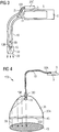
- FIG. 4 shows a lighting device 100, in which a light-emitting comparator is integrated.
- the short-wave radiation emitted by the radiation source 5 is coupled into a light guide 10 at one end 10A of the light guide and converted into converted visible light by means of a converter material 15 after being transported through the light guide 10 at the other end 10B of the light guide.
- the converter material 15 is located directly at the end 10B of the optical fiber 10 to minimize the unintended emission of short wavelength radiation.
- the converted visible light 20 is, for example, in the transparent body 35 is coupled to a solid glass body and is reflected by the reflective coating 35A on the surface of the transparent body 35, so that a directional radiation of the converted light takes place on a surface 40 to be illuminated.
- the transparent body 35 has a parabolic shape.
- the converter material 15 is located at the focal point of this parabolic mirror in order to achieve a particularly good focus of the converted radiation.
- a short-wave radiation-reflecting coating 45 is arranged on the light exit surface 35D of the transparent body 35, which prevents the unintentional emission of unconverted short-wave radiation.
- the transparent body 35 may also be a hollow body, for example a curved mirror. This hollow body may then have on the light exit surface 35D a transparent to visible light cover, which is coated with the UV reflective coating 45.
- the UV reflective coating 45 may be a dielectric mirror tuned to the wavelength of the short wavelength radiation source.
- the reflective coating 35A may be a mirrored surface or allow for total reflection of the converted radiation by refractive index jump, or may include a combination of a mirrored surface having a refractive index jump. It is possible, for example, for one subarea to be mirrored and another subarea to have flat angles of incidence of light and therefore reflect losslessly by refractive index jump. Furthermore, a low-index intermediate layer under the reflective coating 35A is also possible.
- the geometrical 3D shape of the transparent body 35 can furthermore be designed such that the parabolic curvature differs into two sectional planes rotated relative to one another about the optical axis are, which then results in an elliptical light distribution.
- Such lighting devices 100 can produce a sharp light spot 40 and can be used, for example, as reading lamps, spotlights, also theater spotlights and spotlights.
- the in FIG. 5 is shown, a rectangular area to be illuminated 40 illuminated.
- the transparent body 35 has a long parabolic shape having, for example, a light exit surface 35D having a rectangular cross section. It can be clearly seen that the geometric shape of the light exit surface 35D largely also determines the geometric shape of the surface 40 to be illuminated, wherein the surface 40 to be illuminated is somewhat elongated than the light exit surface 35D.
- the short-wave light 11 is transported via a light guide and coupled into the transparent body 35 at the end 10B of the light guide 10.
- the transparent body 35 there is a bore which runs along the main axis of the transparent body 35 and is filled with converter material 15, which converts the short-wave light 11 into visible light 20.
- This converter material 15 may include, for example, nanoparticles, since in these the light scattering is reduced and so the luminous intensity of the bore is more uniform with the converter.
- the converted visible light 20 can then be reflected on the surface of this transparent body 35, for example by means of a refractive index jump or by a mirror coating or both, and through the light exit surface 35D are disconnected.
- the light-emitting surface 35D of the transparent body 35 is provided with a UV-reflecting coating 45 which prevents the emission of unconverted short-wave radiation.
- FIG. 6 shows a similar illumination device 100, as in FIG. 5 shown illumination device.
- a photoconductive medium 35C for example, a glass rod or a glass fiber, which is light-conductively connected to the end 10B of the light guide 10.
- the light-conducting medium can be a glass rod which has a converter coating.
- the glass rod for example, less than 1 mm thick, for example, less than 100 microns.
- Such lighting devices can be used for example as a display backlighting with high coupling efficiency in the backlight plate, for example, in laptops.
- the photoconductive medium 25C comprises no converter material.
- the light exit surface 35D may preferably also be roughened or contain scattering centers and thus be itself a secondary luminous surface.
- Such an embodiment is advantageous when an open-form illuminated surface is required, which can optionally be imaged optically on surfaces or objects to be illuminated.
- the light-conducting medium 35C may preferably also be roughened on its surface (roughened rod or fiber) or contain scattering centers, thereby improving the light extraction from the light-conducting medium.
- the short-wave radiation-reflecting coating can then also be arranged together with the converter coating 15 and 45 on the light exit surface 35D.
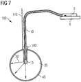
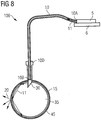
- FIG. 7 shows a ceiling lighting device 100, in which a lamp suspension 110 is provided for attachment to the ceiling.
- the short-wave light transported by the light guide 10 is converted at the end of the light guide by means of the converter material 15 into visible light 20 and then into a spherical transparent body 35, which may be either a solid or a hollow body coupled.
- an optical fiber attachment 10D is still present on the transparent body 35.
- On the outer surface of this transparent spherical body may then be a UV reflective coating 45, which reflects unconverted short-wave radiation.
- the short-wave radiation 11 at the end 10A of the optical waveguide 10 is coupled into the transparent body 35 by means of an optical component 30, which may comprise a scattering lens or scattering optics, which may again be a hollow or a solid ball body and may for example consist of glass or plastic.
- an optical component 30 which may comprise a scattering lens or scattering optics, which may again be a hollow or a solid ball body and may for example consist of glass or plastic.
- a converter material 15 to be arranged on the inner surface of the hollow body 35, which converts the short-wave radiation 11 into converted light 20.
- a UV-reflecting coating 45 may then be present, which reflects or absorbs unconverted short-wave radiation.
- this ceiling lighting device 100 is that the irradiation density of the converter material 15 is lower compared to an arrangement in which this material 15 is arranged directly at the end 10A of the light guide 10. As a result, a higher conversion efficiency can be achieved.
- the optical component 30 may also include a deflection prism that provides for irradiation of the short wavelength radiation at a shallow angle so that it is often reflected back to the transparent body 35 at the short wavelength radiation reflective coating so that more uniform illumination after conversion is reached.
- FIG. 9 shows a vehicle 150 having a headlight 160 that includes a light-emitting device. It can be seen that the transparent body 35 is arranged in the headlight 160 as well as optionally further optical components 30, which ensure a directed radiation of the generated radiation 20. Furthermore, a heat sink 170 is provided, which is used for cooling the motor, wherein particularly advantageous the radiation source 5 is arranged with the heat sink 6 so close to the cooling 170, that a thermal coupling takes place and the cooling 170 and the radiation source 5 cools.
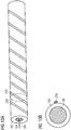
- the Figures 10A and 10B show a light guide 10 comprising a core region 10E, and a cladding region 10C surrounding the core region 10E, the core region having a higher refractive index than the cladding region.
- the core region can reflect light and radiation, eg. B. conduct shortwave radiation.
- a first electrically conductive connection 25A is present, which winds around the cladding region or is arranged circumferentially around the optical waveguide and thus can detect possible damage or breakage of the optical waveguide at the various points.
- Fig. 10B is a cross section through the light guide at the 200 marked position.
- two electrically conductive connections could also run on the cladding region 10C in such a way, for example. B. as described above form a closed circuit or the capacitor effect between the parallel connections can be determined and thus damage to the light guide could be detected.
- a first electrically conductive connection 25A and a second electrically conductive Connection 25B in the cladding region 10C of the light guide 10th Fig. 11B is again a cross section through the in Fig. 11A shown light guide.
- the two electrically conductive compounds can be z. B. parallel to the main axis 300 of the optical fiber, or as in Figs. 10A and 10B also shown to be tortuous.
Landscapes
- Physics & Mathematics (AREA)
- General Engineering & Computer Science (AREA)
- Engineering & Computer Science (AREA)
- General Physics & Mathematics (AREA)
- Optics & Photonics (AREA)
- Analytical Chemistry (AREA)
- Chemical & Material Sciences (AREA)
- Optical Couplings Of Light Guides (AREA)
- Planar Illumination Modules (AREA)
- Arrangement Of Elements, Cooling, Sealing, Or The Like Of Lighting Devices (AREA)
- Non-Portable Lighting Devices Or Systems Thereof (AREA)
- Semiconductor Lasers (AREA)
- Light Guides In General And Applications Therefor (AREA)
Description
Die Erfindung betrifft Licht emittierende Vorrichtungen mit einem Lichtleiter.The invention relates to light-emitting devices with a light guide.
Licht emittierende Vorrichtungen mit einem Lichtleiter sind beispielsweise aus der Druckschrift
Die Druckschriften
Diese Aufgabe wird gelöst durch eine Licht emittierende Vorrichtung nach Anspruch 1. Weitere Ausgestaltungen der Lichtemittierenden Vorrichtung sowie Beleuchtungseinrichtungen mit der Licht emittierenden Vorrichtung und ein Display sowie ein Fahrzeug mit der Licht emittierenden Vorrichtung sind Gegenstand weiterer Ansprüche. Eine Ausführungsform der Erfindung stellt eine Licht emittierende Vorrichtung zur Verfügung, die umfasst:
- eine, eine Strahlung erster Wellenlänge emittierende Strahlungsquelle,
- einen Lichtleiter, in dem die von der Strahlungsquelle emittierte Strahlung eingekoppelt wird, und
- ein Konvertermaterial, das die durch den Lichtleiter transportierte Strahlung in Licht einer zweiten, längeren Wellenlänge konvertiert.
- a radiation source emitting radiation of the first wavelength,
- a light guide in which the radiation emitted by the radiation source is coupled in, and
- a converter material that converts the radiation transported by the light guide into light of a second, longer wavelength.
Die Effizienz der Lichtkonversion kann bei dieser Licht emittierenden Vorrichtung dadurch erhöht sein, dass das Konvertermaterial nicht in unmittelbarer Nähe der Strahlung emittierenden Strahlungsquelle angeordnet ist, sondern durch den Lichtleiter von der Strahlungsquelle getrennt ist. Dadurch kann beispielsweise eine Reabsorption des konvertierten Lichts der längeren, zweiten Wellenlänge durch die Strahlungsquelle vermindert werden. Weiterhin wird der Ort der Erzeugung des sichtbaren Lichts von dem Ort der Wärmeerzeugung, der Strahlungsquelle räumlich getrennt, mit der Folge, dass die Betriebstemperatur des Konvertermaterials gesenkt werden kann, was deren Zuverlässigkeit erhöhen kann. Eine derartige Beabstandung des Konvertermaterials von der Strahlungsquelle kann auch als "remote phosphor configuration" bezeichnet werden. Durch die Konversion kann die Strahlung der ersten Wellenlänge in - bevorzugt sichtbares Licht- einer zweiten Wellenlänge konvertiert werden, wobei die zweite Wellenlänge größer ist als die erste Wellenlänge der anregenden Strahlung.The efficiency of the light conversion can be increased in this light-emitting device in that the converter material is not arranged in the immediate vicinity of the radiation-emitting radiation source, but is separated by the light guide from the radiation source. As a result, for example, a reabsorption of the converted light of the longer, second wavelength can be reduced by the radiation source. Furthermore, the location of the generation of the visible light from the location of the heat generation, the radiation source is spatially separated, with the result that the operating temperature of the converter material can be lowered, which can increase their reliability. Such a spacing of the converter material from the radiation source can also be referred to as "remote phosphor configuration". As a result of the conversion, the radiation of the first wavelength can be converted into-preferably visible light-a second wavelength, the second wavelength being greater than the first wavelength of the exciting radiation.
Bei einer weiteren Ausführungsform der Erfindung emittiert die Strahlen emittierende Strahlungsquelle kurzwellige Strahlung im Bereich von 210 bis 500 nm, bevorzugt im Bereich von 210 nm bis 420 nm, weiter bevorzugt im Bereich von 360 nm bis 420 nm oder im eher blauen Bereich von etwa 420 nm bis 500 nm. Das nach der Konversion ausgestrahlte -bevorzugt sichtbare- konvertierte Licht der zweiten Wellenlänge weist dabei eine längere Wellenlänge auf als die ursprünglich von der Strahlungsquelle emittierte Strahlung und kann in Abhängigkeit von dieser Strahlung in einem Wellenlängenbereich von 400 bis 800 nm liegen.In a further embodiment of the invention, the radiation-emitting radiation source emits short-wave radiation in the range of 210 to 500 nm, preferably in the range of 210 nm to 420 nm, more preferably in the range of 360 nm to 420 nm or in the more blue range of about 420 nm up to 500 nm. The preferably converted-converted light of the second wavelength emitted after the conversion has a longer wavelength than the radiation originally emitted by the radiation source and can be dependent on of this radiation in a wavelength range of 400 to 800 nm.
Das Konvertermaterial kann dabei insbesondere ein Leuchtstoff sein, der durch die von der Strahlungsquelle emittierte Strahlung angeregt werden kann, beispielsweise zu Fluoreszenz. Im nahen UV können beispielsweise Leuchtstoffe auf O-xidbasis, wie zum Beispiel Barium-Magnesium-Aluminate, die mit Europium dotiert sind, verwendet werden, wie zum Beispiel BaMgAl10O17:Eu2+. Verwendet werden können auch Strontium-Magnesium-Aluminate, die ebenfalls mit Europium dotiert sind, wie zum Beispiel SrMgAl10O17:Eu2+ sowie Chlorapatite mit Strontium, Barium oder Calcium der Formel (Sr, Ba, Ca)5(PO4)3Cl:Eu2+. Es können auch Bariumaluminate, zum Beispiel Ba3Al28O45:Eu2+ verwendet werden. All die genannten Verbindungen emittieren Licht im blauen Wellenlängenbereich, wenn sie im nahen UV gepumpt werden. Grün emittierende Leuchtstoffe sind beispielsweise SrAl2O4:Eu2+. Grün bis grüngelb emittierende Leuchtstoffe sind beispielsweise Chloro-Silikate der Formel Ca8Mg(SiO4)4Cl2:Eu2+, Mn2+, die mit Europium oder Mangan dotiert sind, sowie Thiogallate der allgemeinen Formel AGa2S4:Eu2+, Ce2+, wobei A ausgewählt sein kann aus Calcium, Strontium, Barium, Zink und Magnesium. Weiterhin können als rot emittierende Leuchtstoffe und Konvertermaterialien beispielsweise Erdalkali-substituierte Strontium-Sulfide der allgemeinen Formel ((A, Sr)S:Eu2+ mit A= Erdalkalimetallionen, sowie Nitridosilikate der Formel M2Si5N5N8:Eu2+ mit M = Ca oder Sr verwendet werden.The converter material may in particular be a phosphor which can be excited by the radiation emitted by the radiation source, for example to fluorescence. In the near UV, for example, oxide-based phosphors, such as barium-magnesium aluminates doped with europium, may be used, such as BaMgAl 10 O 17 : Eu 2+ . It is also possible to use strontium magnesium aluminates which are likewise doped with europium, for example SrMgAl 10 O 17 : Eu 2+ and also chlorapatites with strontium, barium or calcium of the formula (Sr, Ba, Ca) 5 (PO 4 ) 3 Cl: Eu 2+ . It is also possible to use barium aluminates, for example Ba 3 Al 28 O 45 : Eu 2 +. All these compounds emit light in the blue wavelength range when pumped in the near UV. Green-emitting phosphors are, for example, SrAl 2 O 4 : Eu 2+ . Green to green-yellow emitting phosphors are, for example, chloro-silicates of the formula Ca 8 Mg (SiO 4 ) 4 Cl 2 : Eu 2+ , Mn 2+ , which are doped with europium or manganese, and thiogallates of the general formula AGa 2 S 4 : Eu 2+ , Ce 2+ , where A may be selected from calcium, strontium, barium, zinc and magnesium. Furthermore, as the red-emitting phosphors and converter materials, for example, alkaline earth-substituted strontium sulfides of the general formula ((A, Sr) S: Eu 2+ with A = alkaline earth metal ions, and nitridosilicates of the formula M 2 Si 5 N 5 N 8 : Eu 2+ with M = Ca or Sr.
Die Konvertermaterialien, beziehungsweise Leuchtstoffe können auch derart eingesetzt werden, dass diese bei Anregung mit kurzwelliger Strahlung sichtbares Weißlicht emittieren und es somit zu einer Konversion der kurzwelligen Strahlung in sichtbares Weißlicht kommt. Eine Mischung von beispielsweise 47 Gew-% Strontium-Chlorapatit, 48 Gew-% Strontium-Aluminat und 5 Gew-% Nitridosilikate kann bei einer Anregung bei 405 nm Weißlicht mit einem Farbort x = 0,354 und y = 0,386 in der CIE-Norm Farbtafel emittieren. Bei weiteren Ausführungsformen der Erfindung kann durch die Konversion der Strahlung erster Wellenlänge auch sichtbares Licht der zweiten Wellenlänge resultieren, dass keinen Weislichteindruck beim Betrachter hinterlässt, sondern z. B. gelb, grün rot oder eine andere beliebige Farbe aufweist. Weiterhin ist es möglich, dass lichtemittierende Vorrichtungen Licht emittieren, dass eine Mischung aus nicht konvertierter kurzwelliger Strahlung und konvertierten Licht ist.The converter materials or phosphors can also be used in such a way that they emit visible white light upon excitation with short-wave radiation and thus lead to a conversion of the short-wave radiation into visible white light comes. A mixture of, for example, 47 wt% strontium chloroapatite, 48 wt% strontium aluminate, and 5 wt% nitridosilicates can emit when excited at 405 nm white light with a color location x = 0.354 and y = 0.386 in the CIE standard color chart , In further embodiments of the invention, the conversion of the radiation of the first wavelength can also result in visible light of the second wavelength, which does not leave a white light impression in the viewer, but z. B. yellow, green red or any other color. Furthermore, it is possible for light emitting devices to emit light that is a mixture of unconverted short wavelength radiation and converted light.
Der Lichtleiter kann beispielsweise Fasern umfassen, die ein Material enthalten, das ausgewählt ist aus Glas und Kunststoff. Somit kann der Lichtleiter auch Glasfaserkabel oder Lichtleitstäbe umfassen. Zum Einkoppeln und zum Transport des von der Strahlungsquelle bei einigen Ausführungsformen der Erfindung emittierten kurzwelligen Lichts, z. B. UV-Lichts sind besonders gut Lichtleiter auf der Basis von Glas geeignet. Der Lichtleiter kann wie eine Faser aufgebaut sein, wobei ein Querschnitt durch eine derartige Faser einen Kernbereich mit hohen Brechungsindex zeigt, der von einem Mantelbereich mit geringeren Brechungsindex als der Kernbereich umgeben ist. Der Kernbereich ist dabei in der Lage eingekoppelte Moden von Licht und kurzwelliger Strahlung z. B. mittels Interferenz und Reflexion zu transportieren.For example, the optical fiber may comprise fibers containing a material selected from glass and plastic. Thus, the light guide may also include fiber optic cables or light guide rods. For launching and transporting the shortwave light emitted by the radiation source in some embodiments of the invention, e.g. B. UV light are particularly well suited optical fiber based on glass. The optical fiber may be constructed like a fiber, wherein a cross section through such a fiber shows a high refractive index core region surrounded by a cladding region having a lower refractive index than the core region. The core region is capable of coupled modes of light and short-wave radiation z. B. by means of interference and reflection.
Bei einer weiteren Ausführung der Erfindung können auch mehrere Lichtleiter vorhanden sein, die beispielsweise zu einem Lichtleiterbündel zusammengefasst werden, wobei jeder einzelne Lichtleiter separat die von der Strahlungsquelle emittierte Strahlung erster Wellenlänge nach der Einkopplung zum Konvertermaterial transportieren kann. Eine weitere Ausführungsform einer erfindungsgemäßen Licht emittierenden Vorrichtung kann dabei auch mehrere Strahlungsquellen umfassen, wobei es beispielsweise möglich ist, dass für je einen Lichtleiter eine Strahlungsquelle vorhanden ist. Die von diesen Strahlungsquellen emittierte Strahlung erster Wellenlänge kann dann mittels der Lichtleiter in zum Beispiel einem Lichtleiterbündel gebündelt werden und nach dem Transport der Strahlung durch das Lichtleiterbündel mittels des Konvertermaterials in das Licht der zweiten, längeren Wellenlänge konvertiert werden. Dabei ist es auch möglich, dass die Strahlung der verschiedenen Strahlungsquellen, die in verschiedene Lichtleiter eingekoppelt wird, mittels unterschiedlicher Konvertermaterialien in sichtbares Licht unterschiedlicher zweiter Wellenlänge konvertiert wird, wobei durch eine Mischung dieses sichtbaren Lichts verschiedener Wellenlänge dann ein homogener Weißlichteindruck für den Betrachter resultiert. So können z. B. die noch weiter unter beschriebenen optische Bauteile und/oder transparenten Körper für ein derartige Mischung verwendet werden.In a further embodiment of the invention, a plurality of optical fibers may also be present, which are combined, for example, to form an optical fiber bundle, each individual optical fiber separately being emitted by the radiation source Radiation first wavelength after coupling to the converter material can transport. A further embodiment of a light-emitting device according to the invention may also comprise a plurality of radiation sources, it being possible, for example, for a radiation source to be present for each one light guide. The radiation of the first wavelength emitted by these radiation sources can then be bundled by means of the light guides into, for example, an optical fiber bundle and converted into the light of the second, longer wavelength after the radiation has been transported through the optical fiber bundle by means of the converter material. It is also possible that the radiation of the various radiation sources, which is coupled into different optical fibers is converted by means of different converter materials in visible light of different second wavelength, resulting in a mixture of this visible light of different wavelength then a homogeneous white light impression for the viewer. So z. For example, the optical components and / or transparent bodies described below may be used for such a mixture.
Weiterhin kann bei einer Licht emittierenden Vorrichtung nach einem weiteren Ausführungsbeispiel der Erfindung ein optisches Bauteil vorhanden sein, das mit dem konvertierten Licht oder mit der aus dem Lichtleiter austretenden Strahlung erster Wellenlänge wechselwirkt. Dieses optische Bauteil kann beispielsweise mit dem konvertierten Licht oder mit der aus dem Lichtleiter austretenden Strahlung erster Wellenlänge, z. B. kurzwelliger Strahlung mittels Streuung, Brechung, Reflexion, Umlenkung oder Beugung wechselwirken. Das optische Bauteil kann beispielsweise eine Linse umfassen, die zum Beispiel das konvertierte Licht bündeln kann. Wenn die Licht emittierende Vorrichtung mehrere Lichtleiter enthält, die beispielsweise zu einem Bündel zusammengefasst sind, so kann dieses Bündel beispielsweise in eine gemeinsame Bohrung des optischen Bauteils gesteckt werden.Furthermore, in a light-emitting device according to a further exemplary embodiment of the invention, an optical component can be present which interacts with the converted light or with the radiation of the first wavelength emerging from the light guide. This optical component, for example, with the converted light or with the exiting from the light guide radiation of the first wavelength, z. B. short-wave radiation by means of scattering, refraction, reflection, deflection or diffraction interact. The optical component may, for example, comprise a lens which may, for example, focus the converted light. When the light-emitting Device contains a plurality of optical fibers, which are combined, for example, into a bundle, so this bundle can be inserted, for example, in a common bore of the optical component.
Bei einer weiteren Ausführungsform der Erfindung kann das Konvertermaterial an einem Ende des Lichtleiters angeordnet sein und dieses Ende im Brennpunkt des optischen Bauteils angeordnet sein.In a further embodiment of the invention, the converter material can be arranged at one end of the optical waveguide and this end can be arranged in the focal point of the optical component.
Bei einer derartigen Licht emittierenden Vorrichtung wird dann das mittels des Konvertermaterials erzeugte sichtbare Licht längerer Wellenlänge parallel durch das optische Bauteil, beispielsweise eine Linse abgestrahlt, sodass eine parallele gerichtete Lichtemission des konvertierten Lichts in eine besondere Abstrahlrichtung möglich ist.In such a light-emitting device, the longer-wavelength visible light generated by the converter material is then radiated in parallel through the optical component, for example, a lens, so that parallel directed light emission of the converted light in a particular radiation direction is possible.
Weiterhin ist es auch möglich, dass das Ende des Lichtleiters mit dem Konvertermaterial außerhalb des Brennpunkts des optischen Bauteils angeordnet ist und dann beispielsweise zur Defokussierung des mittels Konversion erzeugten sichtbaren Lichts dienen kann. Auf diese Weise lässt sich z. B. die Abstrahlung einer Punklichtquelle, die durch die Konversion der z. B. kurzwelligen Strahlung (z. B. UV-Strahlung) zu sichtbarer Strahlung an einem Ende einer Glasfaser als Lichtleiter entstehen kann, aufweiten mit der Folge, dass dann auch eine größere Fläche durch die Punktlichtquelle beleuchtet werden kann.Furthermore, it is also possible that the end of the optical waveguide with the converter material is arranged outside the focal point of the optical component and can then serve, for example, for defocusing the visible light produced by means of conversion. In this way, z. B. the radiation of a Punklichtquelle, which is due to the conversion of z. B. short-wave radiation (eg., UV radiation) to visible radiation at one end of a glass fiber can arise as a light guide, expand with the result that then a larger area can be illuminated by the point light source.
Die Strahlungsquelle kann beispielsweise eine kurzwellige Strahlungsquelle, insbesondere eine UV-Laserdiode, zum Beispiel eine N-basierte Laserdiode wie eine InGaN-Laserdiode umfassen. Insbesondere können Materialien der allgemeinen Formel AlxInyGazN mit x, y, z ≥ 0 und x+y+z = 1 verwendet werden, z. B. eine Laserdiode mit einer Emissionswellenlänge von 365 nm bis 425 nm mit einem In-Gehalt von 0-10 Atom% (z. B. x = 0; y = 0-0,1; z = 0,9-1,0) in der lichterzeugenden Schicht. UV-Laserdioden sind besonders gut geeignet, eine gerichtete UV-Strahlung zu emittieren, die gut in einen Lichtleiter eingekoppelt werden kann.The radiation source may comprise, for example, a short-wave radiation source, in particular a UV laser diode, for example an N-based laser diode such as an InGaN laser diode. In particular, materials of the general Formula Al x In y Ga z N where x, y, z ≥ 0 and x + y + z = 1 are used, e.g. For example, a laser diode having an emission wavelength of 365 nm to 425 nm with an In content of 0-10 at% (eg, x = 0, y = 0-0.1, z = 0.9-1.0 ) in the photogenerating layer. UV laser diodes are particularly well suited to emit a directional UV radiation that can be well coupled into an optical fiber.
Erfindungsgemäße Licht emittierende Vorrichtungen können beispielsweise eine besonders gute optische Abbildungsqualität dadurch erreichen, dass eine helle, punktartige Lichtquelle dadurch realisiert wird, dass die Strahlung erster Wellenlänge (z. B. UV-Strahlung) der Strahlungsquelle durch einen Lichtleiter, der beispielsweise eine Glasfaser ist, transportiert wird. Besonders gute Punktlichtquellen lassen sich durch die Verwendung von UV-Lasern mit Lichtleitern und Konvertermaterialien erzielen. Punktlichtquellen weisen eine eng begrenzte räumliche Ausdehnung auf, wobei ein großer Kontrast zwischen beleuchten und nicht beleuchteten Bereichen vorhanden ist.For example, light-emitting devices according to the invention can achieve a particularly good optical imaging quality by realizing a bright, point-like light source by virtue of the radiation of the first wavelength (eg UV radiation) of the radiation source passing through an optical waveguide which is, for example, a glass fiber. is transported. Particularly good point light sources can be achieved by using UV lasers with optical fibers and converter materials. Point light sources have a narrow spatial extent, with a large contrast between illuminated and non-illuminated areas.
Die Strahlungsquelle kann zur Abfuhr der Verlustwärme beispielsweise mit einer Wärmesenke verbunden sein. Die Strahlungsquelle kann dabei direkt mit der Wärmesenke verbunden sein, oder in thermischen Kontakt mit ihr stehen.The radiation source can be connected to dissipate the heat loss, for example, with a heat sink. The radiation source can be directly connected to the heat sink, or be in thermal contact with it.
In einer weiteren Ausführungsform von erfindungsgemäßen Licht emittierenden Vorrichtungen kann das Konvertermaterial Nanopartikel umfassen. Der Vorteil von Nanopartikeln kann darin bestehen, dass bei diesen die Lichtstreuung vermindert wird und so die Leuchtstärke des von dem Konvertermaterial emittierten sichtbaren Lichts gleichmäßiger wird. Vorteilhafterweise weisen die Nanopartikel Partikeldurchmesser auf, die bei einigen Nanometern liegen, beispielsweise zwischen 2 bis 50 nm, weiter bevorzugt zwischen 2 nm bis 10 nm, da derartig kleine Nanopartikel besonders gut eine Lichtstreuung des konvertierten sichtbaren Lichts vermindern. Weiterhin kann auch der Partikeldurchmesser die Wellenlänge des konvertierten Licht z. B. aufgrund des Quantengrößen-Effekts beeinflussen. So erzeugen Nanopartikel mit kleineren Durchmessern konvertiertes Licht mit kürzerer Wellenlänge im Vergleich zu Nanopartikeln mit größeren Durchmessern.In a further embodiment of light-emitting devices according to the invention, the converter material may comprise nanoparticles. The advantage of nanoparticles can be that they reduce the light scattering and thus the luminous intensity of the visible light emitted by the converter material becomes more uniform. Advantageously, the nanoparticles have particle diameters which at some nanometers, for example between 2 to 50 nm, more preferably between 2 nm to 10 nm, since such small nanoparticles reduce light scattering of the converted visible light particularly well. Furthermore, the particle diameter, the wavelength of the converted light z. B. due to the quantum size effect. For example, smaller diameter nanoparticles produce converted light of shorter wavelength compared to larger diameter nanoparticles.
Bei allen Ausführungsformen einer erfindungsgemäßen Licht emittierenden Vorrichtung ist auch zusätzlich eine Detektionsvorrichtung vorhanden, die eine Beschädigung des Lichtleiters detektieren und damit anzeigen kann.In all embodiments of a light-emitting device according to the invention, a detection device is additionally present which can detect and thus indicate damage to the light guide.
Dies ist besonders vorteilhaft, da dadurch schnell detektiert werden kann, ob der Lichtleiter beschädigt ist und damit auch für den Betrachter eventuell schädliches kurzwelliges Licht nach außen abgestrahlt wird.This is particularly advantageous because it can be detected quickly, whether the optical fiber is damaged and thus possibly harmful to the viewer shortwave light is emitted to the outside.
Besonders vorteilhaft kontrolliert die Detektionsvorrichtung, die eine Beschädigung des Lichtleiters detektieren kann, auch eine Energieversorgung (Strom- und/oder Spannungsversorgung) für die bevorzugt kurzwellige Strahlung emittierende Strahlungsquelle und kann somit bei Beschädigung des Lichtleiters die Energieversorgung abstellen, mit der Folge, dass auch die potentiell gefährliche Emission von kurzwelliger Strahlung, z. B. UV-Strahlung aus dem beschädigten Lichtleiter unterbrochen wird.Particularly advantageously, the detection device, which can detect damage to the light guide, also controls a power supply (current and / or voltage supply) for the preferably short-wave radiation emitting radiation source and can thus turn off the power supply in case of damage to the light guide, with the result that the potentially dangerous emission of short-wave radiation, eg. B. UV radiation from the damaged optical fiber is interrupted.
Die Detektionsvorrichtung umfasst einen ersten Detektor zur Detektion des konvertierten Lichts, wobei dann die Detektion des konvertierten Lichts die Funktionsfähigkeit des Lichtleiters anzeigt.The detection device comprises a first detector for detecting the converted light, wherein then the detection of the converted light indicates the operability of the light guide.
Bei der Konversion der Strahlung erster Wellenlänge, bevorzugt kurzwellige Strahlung kann das mittels des Konvertermaterials erzeugte Licht der zweiten, längeren, z. B. sichtbaren Wellenlänge von dem Konvertermaterial isotrop in alle Richtungen emittiert werden. Da die Detektionsvorrichtung an einem Ende des Lichtleiters vorhanden ist und das Konversionsmaterial an dem anderen Ende des Lichtleiters vorhanden ist, kommt es zu einer Einkopplung von konvertierten Licht in den Lichtleiter, wobei dieses konvertierte Licht durch den Lichtleiter hindurch wieder zum ersten Detektor am anderen Ende des Lichtleiters transportiert wird. Eine Detektion von konvertiertem Licht durch den ersten Detektor zeigt an, dass der Lichtleiter funktionsfähig und unversehrt ist. In dem Fall, dass kein konvertiertes Licht mehr durch den ersten Detektor detektiert wird, ist davon auszugehen, dass beispielsweise aufgrund eines Bruchs des Lichtleiters ein Transport des konvertierten Lichts vom Konvertermaterial zum ersten Detektor nicht mehr möglich ist. In diesem Fall ist es dann besonders vorteilhaft, wenn der erste Detektor beziehungsweise die Detektionsvorrichtung eine Energieversorgung der Strahlungsquelle ausschalten kann. Beispielsweise kann die Detektionsvorrichtung Bestandteil einer Schaltungsanordnung sein, die die Energieversorgung der Strahlungsquelle mit Strom versorgt und die bei fehlender Detektion des konvertierten Lichts diesem Stromkreis unterbricht. Weiterhin besteht die Möglichkeit, dass die Strahlungsquelle, zum Beispiel eine UV-Laserdiode mit kleiner Leistung beim Anschalten der Licht emittierenden Vorrichtung angeschaltet wird und dann beim Hochfahren des Lasers die ursprüngliche Einschaltvorrichtung für den Laser deaktiviert wird und stattdessen eine Steuerungsschaltung, bei der die Detektionsvorrichtung eine Komponente bildet, die Steuerung des Lasers übernimmt. Somit wird dann der Laser nur noch in Abhängigkeit von einer erfolgten Detektion des konvertierten Lichts durch die Detektionsvorrichtung betrieben und kann bei nicht mehr vorhandener Detektion des konvertierten Lichts sofort abgeschaltet werden. Der erste Detektor ist an ein Ende eines Lichtleiters lichtleitend angekoppelt wobei am anderen Ende dieses Lichtleiters dann das Konvertermaterial angeordnet ist. Dieser Lichtleiter kann Bestandteil eines größeren Lichtleiterverbundes, beispielsweise eines Lichtleiterbündels, sein. In diesem Fall können dann die anderen Lichtleiter dieses Bündels mit der Strahlungsquelle verbunden sein und z. B. nur diese eine Lichtleiterfaser mit dem ersten Detektor verbunden sein. Es ist auch möglich einen Strahlteiler im Lichtleiter anzubringen, der zumindest Teile des durch den Lichtleiter rücktransportierten konvertierten Lichts zu dem ersten Detektor leitet (siehe z. B.
Weiterhin können zwischen dem Ende des Lichtleiters und dem Konvertermaterial auch ein oder mehrere Beschichtungen, z. B. dielektrische Spiegel vorhanden sein, die transparent für die Strahlung erster Wellenlänge sind, aber Teile des konvertierten Lichts der zweiten Wellenlänge reflektieren. Beispielsweise besteht die Möglichkeit, dass der oder die dielektrischen Spiegel die Rotanteile des konvertierten Lichts rückreflektieren mit der Folge das die Emission aus dem Lichtleiter verstärkt wird, aber Gelbanteile nicht reflektieren, wobei diese Gelbanteile dann durch den Lichtleiter rückgekoppelt werden und z. B. vom ersten Detektor detektiert werden können.Furthermore, between the end of the light guide and the converter material and one or more coatings, for. For example, dielectric mirrors may be present which are transparent to the first wavelength radiation but which reflect portions of the converted second wavelength light. For example, there is the possibility that the dielectric mirror (s) may reflect back the red portions of the converted light, with the result that the emission from the light pipe is amplified but not reflecting yellow portions, which yellow portions are then fed back through the light pipe and z. B. can be detected by the first detector.
Besonders vorteilhaft ist es, wenn die Strahlungsquelle und der erste Detektor am gleichen Ende des Lichtleiters beziehungsweise Lichtleiterbündels vorhanden sind. Dann kann über Rückreflexion des durch das Konvertermaterial konvertierten sichtbaren Lichts besonders einfach die Funktionsfähigkeit des Lichtleiters über praktisch seine gesamte Länge detektiert werden. Weiterhin ist dann auch eine hohe Gestaltungsfreiheit der Optik, z. B. des optischen Bauteils oder des transparenten Körpers am anderen Ende des Lichtleiters möglich.It is particularly advantageous if the radiation source and the first detector are present at the same end of the light guide or light guide bundle. Then, by way of back reflection of the visible light converted by the converter material, it is particularly easy to detect the functionality of the optical waveguide over virtually its entire length. Furthermore, then a high design freedom of optics, z. B. the optical component or the transparent body at the other end of the light guide possible.
Weiterhin ist zusätzlich ein zweiter Detektor zur Detektion von Umgebungslicht vorhanden. Ein derartiger Detektor soll das durch einen nicht mit der Strahlungsquelle verbundenen Lichtleiter transportierte Umgebungslicht detektieren und als Referenz und Bezugspunkt für das vom ersten Detektor detektierte konvertierte Licht dienen. Mittels des ersten und zweiten Detektors ist es somit einfacher möglich, die Empfindlichkeit der Detektion des konvertierten Lichts zu steigern und somit ein Kontrollsystem für die Funktionsfähigkeit des Lichtleiters zu erhalten, das besonders empfindlich ist.Furthermore, a second detector for detecting ambient light is additionally present. Such a detector is intended to detect the ambient light transported by an optical fiber not connected to the radiation source and to serve as reference and reference point for the converted light detected by the first detector. By means of the first and second detectors, it is thus easier to increase the sensitivity of the detection of the converted light and thus to obtain a control system for the operability of the light guide, which is particularly sensitive.
Die Detektionsvorrichtung, die eine Beschädigung des Lichtleiters detektieren kann, kann zusätzlich auch eine erste elektrisch leitfähige Verbindung umfassen, die in dem Lichtleiter verläuft. Weiterhin sind dann Mittel zur Überprüfung der Funktionsfähigkeit dieser ersten elektrisch leitenden Verbindung vorhanden, wobei die Funktionsfähigkeit der ersten elektrisch leitfähigen Verbindung die Funktionsfähigkeit des Lichtleiters anzeigt.The detection device, which can detect damage to the light guide, may additionally comprise a first electrically conductive connection extending in the light guide. Furthermore, there are then means for checking the operability of this first electrically conductive connection, wherein the operability of the first electrically conductive connection indicates the functionality of the light guide.
Im Falle eines kabelförmigen Lichtleiters, beispielsweise eines Lichtleitstabes oder einer Glasfaser, verläuft die erste elektrisch leitfähige Verbindung vorteilhaft entlang der Hauptachse des Lichtleiters und kann somit besonders empfindlich Beschädigungen des Lichtleiters anzeigen. Mittel zur Überprüfung der Funktionsfähigkeit dieser ersten elektrisch leitfähigen Verbindung können beispielsweise eine Stromversorgung umfassen, die einen elektrischen Puls in die erste elektrisch leitfähige Verbindung, beispielsweise einen Draht gibt, und somit dessen Länge über den Verlauf des Lichtleiters überprüft. Die Länge der ersten elektrisch leitfähigen Verbindung, beispielsweise des Drahtes, wird dann über die Pulsreflexion am anderen Drahtende und die Laufzeit bestimmt.In the case of a cable-shaped optical waveguide, for example a light-conducting rod or a glass fiber, the first electrically conductive connection advantageously runs along the main axis of the optical waveguide and can thus particularly sensitive indicate damage to the optical waveguide. Means for checking the operability of this first electrically conductive connection, for example, include a power supply, which gives an electrical pulse in the first electrically conductive connection, such as a wire, and thus checks its length over the course of the light guide. The length of the first electrically conductive connection, for example of the wire, is then determined by the pulse reflection at the other end of the wire and the transit time.
Weiterhin ist es möglich, dass zusätzlich eine zweite elektrisch leitfähige Verbindung durch den Lichtleiter verläuft, die mit der ersten elektrisch leitfähigen Verbindung einen Stromkreis bildet und weiterhin die Mittel zur Überprüfung der Funktionsfähigkeit dieser ersten elektrisch leitfähigen Verbindung eine Vorrichtung umfassen, die den im Stromkreis fließenden Strom detektieren kann. Dies kann beispielsweise eine Transistorschaltung sein, die nur dann die Strahlungsquelle mit Energie versorgt, wenn der Stromkreis geschlossen ist und somit die Unversehrtheit des Lichtleiters anzeigt. Die erste und zweite elektrisch leitfähige Verbindung können beispielsweise an dem Ende des Lichtleiters, an dem das Konvertermaterial angeordnet ist, zu einer Stromschleife zusammengeführt werden, zum Beispiel mittels einer Metallhülse oder eines Metallrings.Furthermore, it is possible for a second electrically conductive connection to additionally run through the light guide, which forms a circuit with the first electrically conductive connection and furthermore the means for checking the functionality of this first electrically conductive connection comprise a device which measures the current flowing in the circuit can detect. This may be, for example, a transistor circuit which only supplies the radiation source with energy when the circuit is closed and thus indicates the integrity of the light guide. The first and second electrically conductive connections can be brought together, for example, at the end of the optical waveguide on which the converter material is arranged to form a current loop, for example by means of a metal sleeve or a metal ring.
Möglich ist auch, dass die zweite elektrisch leitfähige Verbindung durch den Lichtleiter im Abstand zur ersten elektrisch leitfähigen Verbindung verläuft und die Mittel zur Überprüfung der Funktionsfähigkeit der ersten elektrisch leitenden Verbindung eine zwischen der ersten und zweiten elektrischen Verbindung anliegende Spannung detektieren können. Beispielsweise kann der Kondensatoreffekt zwischen den voneinander beabstandeten ersten und zweiten elektrisch leitfähigen Verbindung gemessen werden und somit über eine Kapazitätsänderung beziehungsweise RC-Resonanzverschiebung die Unversehrtheit des Lichtleiters überprüft werden.It is also possible that the second electrically conductive connection extends through the light guide at a distance from the first electrically conductive connection and the means for checking the operability of the first electrically conductive connection can detect a voltage applied between the first and second electrical connection voltage. For example, the capacitor effect between the spaced-apart first and second electrically conductive connection can be measured, and thus the integrity of the light guide can be checked via a change in capacitance or RC resonance shift.
Vorteilhafterweise weist der Lichtleiter einen Mantelbereich und einen Kernbereich auf, wobei die elektrisch leitfähigen Verbindungen spröder sind als der Kernbereich. In diesem Falle ist dann gewährleistet, dass bei mechanischer Belastung die elektrisch leitfähigen Verbindungen unterbrochen werden, noch bevor der Lichtleiter bricht oder beschädigt wird. Die elektrisch leitfähigen Verbindungen können dabei auch auf oder im Mantelbereich des Lichtleiters verlaufen, oder z. B. zwischen dem Mantelbereich und dem Kernbereich verlaufen. Die elektrisch leitfähigen Verbindungen können im bzw. auf den Lichtleiter auch umlaufend um diesen angeordnet sein, so dass dann vorteilhafterweise eine mechanische Belastung, die auf dem Lichtleiter lastet auch von verschiedenen Richtungen detektiert werden kann. Die elektrisch leitfähigen Verbindungen können auch so dünn ausgeführt sein, das sie bevorzugt brechen, bevor der Lichtleiter, insbesondere der Kernbereich bricht.Advantageously, the optical waveguide has a cladding region and a core region, wherein the electrically conductive compounds are more brittle than the core region. In this case, it is then ensured that under mechanical load, the electrically conductive connections are interrupted, even before the optical fiber breaks or is damaged. The electrically conductive connections can also run on or in the cladding region of the light guide, or z. B. between the cladding region and the core region. The electrically conductive connections can also be arranged circumferentially in or on the optical waveguide, so that then advantageously a mechanical load which rests on the optical waveguide can also be detected from different directions. The electrically conductive connections can also be made so thin that they preferably break before the light guide, in particular the core region breaks.
Unter Sprödigkeit versteht man allgemein die Eigenschaft von Festkörpern, unter Beanspruchung zu Zerbrechen anstatt plastische oder elastische Deformation zu erleiden. In diesem Zusammenhang wird auf das Stichwort "Sprödigkeit" im Römp Chemielexikon, 9. erweiterte und neu bearbeitete Auflage, Georg-Thieme-Verlag Stuttgart, verwiesen, auf dass hiermit voll inhaltlich Bezug genommen wird.Brittleness is generally understood to mean the property of solids under stress to break rather than undergo plastic or elastic deformation. In this context, the keyword "brittleness" in Römp Chemielexikon, 9th extended and revised edition, Georg-Thieme-Verlag Stuttgart, pointed out, that hereby full contentwise reference is made.
Bei einer weiteren Ausführungsform einer erfindungsgemäßen Licht emittierenden Vorrichtung ist ein Ende des Lichtleiters Licht leitend mit einem transparenten Körper verbunden. Beispielsweise ist es möglich, dass ein Ende des Lichtleiters von dem transparenten Körper umgeben ist und zum Beispiel in eine Bohrung des transparenten Körpers gesteckt werden kann. Bei dem transparenten Körper kann es sich beispielsweise um einen Glas- oder Kunststoffkörper handeln, wobei der transparente Körper sowohl ein Hohlkörper als auch massiv ausgebildet sein kann. Der transparente Körper ist vorteilhafterweise transparent für das konvertierte sichtbare Licht oder auch transparent für die durch den Lichtleiter transportierte Strtahlung erster Wellenlänge, bevorzugt kurzwellige Strahlung. Auf zumindest Teilbereichen der Oberfläche des transparenten Körpers können eine kurzwellige Strahlung reflektierende Schicht bzw. eine Strahlung erster Wellenlänge reflektierende Schicht oder entsprechende Absorptionsschichten vorgesehen sein, um beispielsweise eine Emission von nicht konvertiertem kurzwelligen Licht aus der Licht emittierenden Vorrichtung heraus zu verhindern beziehungsweise zu vermindern.In a further embodiment of a light-emitting device according to the invention, one end of the light guide is light-conductively connected to a transparent body. For example, it is possible that one end of the light guide is surrounded by the transparent body and can be plugged, for example, into a bore of the transparent body. The transparent body may be, for example, a glass or plastic body, wherein the transparent body may be both a hollow body and solid. The transparent body is advantageously transparent to the converted visible light or transparent to the Strtahlung transported by the optical fiber first wavelength, preferably short-wave radiation. On at least partial areas of the surface of the transparent body, a short-wave radiation-reflecting layer or a radiation-first wavelength reflecting layer or corresponding absorption layers may be provided, for example to prevent or reduce emission of unconverted short-wave light from the light-emitting device.
Günstigerweise ist das Ende des Lichtleiters Licht leitend mit dem transparenten Körper verbunden oder von diesem umgeben, aus dem die in den Lichtleiter transportierte Strahlung der Strahlungsquelle austritt.Conveniently, the end of the light guide is light-conducting connected to the transparent body or surrounded by this, from which the radiation of the radiation source transported into the light guide exits.
Weiterhin ist es möglich, dass an dem Ende des Lichtleiters, an dem der transparente Körper vorhanden ist, das Konversionsmaterial zur Konversion der Strahlung erster Wellenlänge (z. B. UV-Strahlung) in Licht einer zweiten Wellenlänge (z. B. sichtbares Licht) vorhanden ist.Furthermore, it is possible that at the end of the light guide on which the transparent body is present, the conversion material for the conversion of the radiation of the first wavelength (eg, UV radiation) in light of a second wavelength (eg, visible light).
Weiterhin kann zumindest auf Teilbereichen der Oberfläche des transparenten Körpers eine für das konvertierte Licht reflektierende Beschichtung angeordnet sein. Diese Beschichtung kann dann z. B. das mittels des Konversionsmaterials am Ende des Lichtleiters erzeugte konvertierte sichtbare Licht auf eine zu beleuchtende Fläche bündeln.Furthermore, at least on partial areas of the surface of the transparent body, a coating reflecting the converted light can be arranged. This coating can then z. B. the generated by means of the conversion material at the end of the light guide converted visible light to focus on a surface to be illuminated.
Weiterhin ist es möglich, dass der transparente Körper eine Lichtaustrittsfläche aufweist, deren geometrische Form weitestgehend die Form einer zu beleuchtenden Fläche bestimmt. Beispielsweise ist es möglich, eine runde, ovale oder beispielsweise rechteckige oder dreieckige Lichtaustrittsfläche an den transparenten Körper auszuformen, die dann eine dementsprechende Freiformfläche bilden, die zur Beleuchtung der Umgebung verwendet wird. Auf diese Art und Weise ist es beispielsweise möglich, Punktlichtquellen, die mittels Konversion erzeugtes sichtbares Licht am Ende des Lichtleiters emittieren, in größere Flächen abdeckende Flächenlichtquellen zu überführen. Der transparente Körper kann beispielsweise ein Paraboloid bilden, mit einer runden beziehungsweise ovalen Lichtaustrittsfläche, die dann eine entsprechende Flächenlichtquelle bildet. Beispielsweise kann der transparente Körper eine lang gestreckte, beispielsweise stabförmige Lichtaustrittsfläche aufweisen, die dann zur Beleuchtung größerer Flächen verwendet werden kann, als dies üblicherweise bei Punktlichtquellen der Fall ist.Furthermore, it is possible that the transparent body has a light exit surface whose geometric shape largely determines the shape of a surface to be illuminated. For example, it is possible to form a round, oval or for example rectangular or triangular light exit surface on the transparent body, which then form a corresponding freeform surface, which is used to illuminate the environment. In this way, it is possible, for example, to convert point light sources, which emit visible light generated by means of conversion at the end of the light guide, into surface areas covering larger areas. The transparent body can for example form a paraboloid, with a round or oval light exit surface, which then forms a corresponding surface light source. For example, the transparent body can have an elongate, for example, rod-shaped light exit surface, which can then be used to illuminate larger areas than is usually the case with point light sources.
Beispielsweise ist es möglich, dass in dem transparenten Körper zumindest ein Hohlraum vorhanden ist, in dem das Konvertermaterial angeordnet ist, wobei der Hohlraum lichtleitend mit dem Lichtleiter beziehungsweise einem Ende des Lichtleiters verbunden ist. Der Hohlraum kann beispielsweise lang gestreckt sein und sich dann entlang einer Hauptachse des ebenfalls lang gestreckten transparenten Körpers erstrecken und somit eine Aufweitung der Punktlichtquelle bedingen.For example, it is possible that at least one cavity is present in the transparent body, in which the converter material is arranged, wherein the cavity is light-conducting is connected to the light guide or one end of the light guide. The cavity may, for example, be elongated and then extend along a major axis of the likewise elongate transparent body and thus cause an expansion of the point light source.
Beispielsweise kann auch in dem transparenten Körper ein lichtleitendes Medium, zum Beispiel ein Lichtleitstab oder ein Lichtleiter wie eine Glasfaser, vorhanden sein, der entlang der Hauptachse des transparenten Körpers verläuft, wobei dieses Licht leitende Medium lichtleitend mit dem Ende des Lichtleiters verbunden ist. Die Oberfläche eines derartigen Licht leitenden Mediums kann beispielsweise aufgeraut sein und somit eine Diffusorwirkung entfalten, mittels der besonders einfach das Licht von dem Licht leitenden Medium in den transparenten Körper ausgekoppelt werden kann. In dem Licht leitenden Medium beziehungsweise auf dessen Oberfläche kann das Konversionsmaterial angeordnet werden.For example, a light-conducting medium, for example a light-conducting rod or a light guide such as a glass fiber, may also be present in the transparent body, which runs along the main axis of the transparent body, wherein this light-conducting medium is connected in a light-conducting manner to the end of the light guide. The surface of such a light-conducting medium may, for example, be roughened and thus develop a diffuser effect by means of which the light from the light-conducting medium can be coupled out into the transparent body in a particularly simple manner. In the light-conducting medium or on its surface, the conversion material can be arranged.
Das Konvertermaterial kann beispielsweise schichtförmig im Strahlengang der durch den Lichtleiter transportierten Strahlung erster Wellenlänge angeordnet sein. In diesem Fall wird günstigerweise die Strahlung durch einen Reflektor gebündelt und auf die Konverterschicht geleitet und dort erst in sichtbares Licht konvertiert.The converter material may be arranged, for example, in the form of a layer in the beam path of the radiation of the first wavelength transported through the optical fiber. In this case, the radiation is conveniently bundled by a reflector and passed to the converter layer and converted there only in visible light.
Bei weiteren Ausführungsformen von erfindungsgemäßen Licht emittierenden Vorrichtungen ist eine Strahlung erster Wellenlänge reflektierende, für sichtbares Licht durchlässige Schicht im Strahlengang der Vorrichtung dem Konvertermaterial nachgeschaltet. Diese Schicht kann beispielsweise ein dielektrischer Spiegel für kurzwellige Strahlung sein. Eine derartige Schicht kann vorteilhafterweise eine Emission von nicht konvertierter kurzwelliger Strahlung aus der Licht emittierenden Vorrichtung verhindern und die nicht konvertierte kurzwellige Strahlung zurückreflektieren z. B. auf das Konvertermaterial. Durch eine derartige kurzwellige Strahlung reflektierende Schicht wird somit zum einen die Emission der potentiell schädlichen kurzwelligen Strahlung aus der Licht emittierenden Vorrichtung heraus vermindert beziehungsweise verhindert und gleichzeitig die Effizienz der Lichtkonversion durch die Rückreflexion gesteigert.In further embodiments of light-emitting devices according to the invention, a radiation of the first wavelength-reflecting, visible-light-transmitting layer in the beam path of the device is connected downstream of the converter material. This layer may, for example, be a dielectric mirror for short-wave radiation. Such a layer may advantageously have an emission of prevent unconverted short-wave radiation from the light-emitting device and the unconverted short-wave radiation back reflect z. B. on the converter material. By such a short-wave radiation-reflecting layer is thus on the one hand, the emission of the potentially harmful short-wave radiation from the light-emitting device out or reduced while increasing the efficiency of the light conversion by the back reflection.
Gegenstand weiterer Ausführungsformen der Erfindung ist auch eine Beleuchtungsvorrichtung, die eine der oben genannten Licht emittierenden Vorrichtungen umfasst. Eine derartige Beleuchtungseinrichtung kann beispielsweise eine Lampe, Tischleuchte, Deckenleuchte oder beliebige andere Beleuchtungseinrichtungen sein.Another embodiment of the invention also relates to a lighting device comprising one of the above-mentioned light-emitting devices. Such a lighting device may be, for example, a lamp, table lamp, ceiling light or any other lighting devices.
Gegenstand einer weiteren Ausführungsform der Erfindung ist auch ein Display, das eine der oben genannten Licht emittierenden Vorrichtungen umfasst. Besonders vorteilhaft wird als eine Komponente eines derartigen Displays eine Licht emittierende Vorrichtung verwendet, die einen schmalen Lichtstreifen konvertierten Lichts emittiert. Ein derartiger Lichtstreifen ist zum Beispiel besonders zur Einkopplung in eine Glas-/ Kunststoffplatte zur LCD-Hinterleuchtung geeignet.A further embodiment of the invention is also a display comprising one of the above-mentioned light-emitting devices. It is particularly advantageous to use as a component of such a display a light-emitting device which emits a narrow band of light of converted light. Such a light strip is suitable, for example, especially for coupling into a glass / plastic plate for LCD backlighting.
Somit sind Gegenstand der Erfindung nach weiteren Ausführungsformen auch Displays, bei denen die Hinterleuchtung eine Licht emittierende Vorrichtung wie oben beschrieben, enthält. Die Displays sind bevorzugt nicht selbst emissiv und sind zum Beispiel Flüssigkristalldisplays.Thus, according to further embodiments, the invention also relates to displays in which the backlighting contains a light-emitting device as described above. The displays are preferably not self-emissive and are, for example, liquid crystal displays.
Gegenstand weiterer Ausführungsformen der Erfindung ist auch ein Fahrzeug mit einem Scheinwerfer, der eine Licht emittierende Vorrichtung wie oben beschrieben enthält. Das Fahrzeug kann z. B. ein Kraftfahrzeug oder Schienenfahrzeug sein und einen Motor mit einer Kühlung aufweisen. Dabei ist es vorteilhaft, wenn die Strahlungsquelle der Licht emittierenden Vorrichtung im thermischen Kontakt mit der Kühlung steht. In diesem Fall ist es besonders einfach möglich, nicht nur den Motor sondern auch die Strahlungsquelle der Licht emittierenden Vorrichtung mit der Kühlung zu kühlen.The subject of further embodiments of the invention is also a vehicle with a headlamp which contains a light-emitting device as described above. The vehicle can z. B. be a motor vehicle or rail vehicle and having a motor with a cooling. It is advantageous if the radiation source of the light-emitting device is in thermal contact with the cooling. In this case, it is particularly easy to cool not only the motor but also the radiation source of the light-emitting device with the cooling.
Im Folgenden soll die Erfindung anhand von Ausführungsbeispielen und Figuren noch näher erläutert werden. Bei den Figuren handelt es sich um nicht maßstabsgetreue, schematische Zeichnungen. In den verschiedenen Figuren kennzeichnen mit gleichen Bezugszeichen versehene Elemente gleiche oder gleichwirkende Elemente.
Die Figuren 1 bis 3- zeigen Licht emittierende Vorrichtungen mit einem optischen Bauteil.
- Die Figuren 4 bis 8
- zeigen weitere Licht emittierende Vorrichtungen mit einem transparenten Körper.
- Figur 9
- zeigt schematisch ein Automobil mit einem Scheinwerfer, der eine Licht emittierende Vorrichtung beinhaltet.
Figuren 10A bis 12B- zeigen verschiedene Vergleichsbeispiele eines Lichtleiters mit elektrisch leitfähigen Verbindungen
- Figures 1 to 3
- show light emitting devices with an optical component.
- FIGS. 4 to 8
- show further light-emitting devices with a transparent body.
- FIG. 9
- schematically shows an automobile with a headlamp, which includes a light-emitting device.
- FIGS. 10A to 12B
- show various comparative examples of a light guide with electrically conductive compounds
Der transparente Körper 35 ist mittels der Steckverbindung 17 an dem Lichtleiter 10 befestigt. Zwischen dem Lichtleiter und dem transparenten Körper befindet sich das Konvertermaterial 15, das auch auf dem Lichtleiter aufgebracht sein kann oder mittels einer Bohrung in dem transparenten Körper 35 (Glas- oder Kunststoffkörper) untergebracht sein kann. Dieser transparente Körper 35 ist transparent für das konvertierte Licht 20 und weist auf dessen Oberflächen vorteilhafterweise eine UV absorbierende beziehungsweise UV reflektierende Beschichtung auf (hier nicht gezeigt). Im Strahlengang ist ein optisches Bauteil 30, eine Linse dem transparenten Körper 35 nachgeschaltet. Das Konvertermaterial 15 befindet sich dabei vorteilhafterweise im Fokus (Brennpunkt) des optischen Bauteils 30, sodass das mit dem optischen Bauteil 30 wechselwirkende konvertierte Licht 20 parallel und gerichtet in eine Vorzugsrichtung abgestrahlt wird. Sowohl die Linse als auch der transparente Körper bedingen eine Aufweitung der an Ende 10B des Lichtleiters 10 auftretenden Punktlichtquelle. Das optische Bauteil 30 und der transparente Körper 35 können auch einstückig ausgeformt sein.The
Die in
Anstatt von Bündelungs- oder Fokussierungsoptiken können auch defokussierte Optiken, Zerstreu-Linsen oder -Linsensysteme sowie einstellbare Zoomoptiken bei erfindungsgemäßen Licht emittierenden Vorrichtungen verwendet werden.Instead of focusing or focusing optics, it is also possible to use defocused optics, scattering lenses or lens systems and adjustable zoom optics in light-emitting devices according to the invention.
Derartige Beleuchtungseinrichtungen 100 können einen scharfen Lichtfleck 40 erzeugen und können beispielsweise als Leseleuchten, Scheinwerfer, auch Theaterscheinwerfer und Spotlights eingesetzt werden.
Im Gegensatz zur Beleuchtungseinrichtung 100 der
Durch diese Anordnung kann ein wohl definierter Leuchtstrich gebildet werden, der gleichzeitig eine gleichmäßige Helligkeit durch die Nanopartikel umfassenden Konvertermaterialien ermöglicht. Weiterhin können scharfe Hell-Dunkel-Grenzen durch Positionierung dieser stabartigen Beleuchtungseinrichtung 100 in dem Parabolkörper erzielt werden.By this arrangement, a well-defined luminous line can be formed, which at the same time allows a uniform brightness through the converter materials comprising nanoparticles. Furthermore, sharp cut-off lines can be achieved by positioning this rod-
Es ist auch möglich, dass das lichtleitende Medium 25C kein Konvertermaterial umfasst. Auch bei einer derartigen Anordnung kann die Lichtaustrittsfläche 35D vorzugsweise auch aufgeraut sein oder Streuzentren enthalten und somit selbst eine sekundäre Leuchtfläche sein. Eine derartige Ausführung ist dann vorteilhaft, wenn eine Freiformleuchtfläche benötigt wird, die gegebenenfalls optisch auf zu beleuchtenden Flächen oder Gegenständen abgebildet werden kann. Das Licht leitende Medium 35C kann bevorzugt auf dessen Oberfläche ebenfalls aufgeraut sein (aufgerauter Stab oder Faser) oder Streuzentren enthalten und dadurch die Lichtauskopplung aus dem Licht leitenden Medium verbessert werden. Die kurzwellige Strahlung reflektierende Beschichtung kann dann auch zusammen mit der Konverterbeschichtung 15 und 45 auf der Lichtaustrittsfläche 35D angeordnet sein.It is also possible that the
Bei der Deckenbeleuchtungseinrichtung 100 der
Das optische Bauteil 30 kann auch ein Umlenkprisma umfassen, das für eine Einstrahlung der kurzwelligen Strahlung unter einem flachen Winkel sorgt, so dass diese häufig an der kurzwelligen Strahlung reflektierenden Beschichtung zurück in den transparenten Körper 35 reflektiert wird, so dass nach der Konversion eine gleichmäßigere Ausleuchtung erreicht wird.The
Weiterhin ist es bei allen Vorrichtungen möglich, dass das Konvertermaterial bzw. die Konverter-Nanopartikel im Volumen des transparenten Körpers 35 angeordnet sind, wenn dieser ein Vollkörper ist.
Die
Im Gegensatz zu den
Claims (14)
- A light-emitting device (1) comprising:- a radiation source (5), which emits a radiation having a first wavelength,- an optical waveguide (10), into which the radiation emitted by the radiation source is coupled, and- a converter material (15), which converts the radiation transported through the optical waveguide (10) into light (20) having a second, longer wavelength,- a detection device (25), which can detect damage to the optical waveguide (10), said detection device (25) comprising a first detector (25D) for detecting the converted light (20), wherein the first detector (25D) is present at one end (10A) of the optical waveguide (10) and the converter material (15) is present at another end (10B) of the optical waveguide (10), wherein the light-emitting device is characterized in that a second detector for detecting ambient light is additionally present, wherein the second detector detects the ambient light transported through an optical waveguide that is not connected to the radiation source and serves as a reference and reference point for the converted light detected by the first detector.
- The device as claimed in the preceding claim,
wherein the radiation source (5) comprises a short-wave radiation source, which emits radiation in the range from 210 nm to 500 nm. - The device as claimed in any of the preceding claims,
wherein the converter material (15) comprises nanoparticles. - The device as claimed in the preceding claim,
wherein the detection device (25) is able to switch off a power supply of the radiation source (5) depending on the detection of the converted light. - The device as claimed in claim 4, wherein the radiation source (5) and the first detector (25D) are present at identical ends (10A) of the optical waveguide (10).
- The device as claimed in the preceding claim,- wherein a first electrically conductive connection (25A) runs in the optical waveguide (10), and- means (25C) for checking the functionality of said first electrically conductive connection (25A) are present,- wherein the functionality of the first electrically conductive connection indicates the functionality of the optical waveguide (10).
- The device as claimed in claim 6, wherein a power supply for the radiation source (5) is present, which can be switched off in the case where converted light (20) is not detected.
- The device as claimed in any of claims 6 to 7,- wherein a second electrically conductive connection (25B) runs through the optical waveguide (10), said second connection forming an electric circuit with the first electrically conductive connection (25A), and- the means (25C) for checking the functionality of said first electrically conductive connection comprise a device that can detect the current flowing in the electric circuit.
- The device as claimed in any of claims 6 to 7,- wherein a second electrically conductive connection (25B) runs through the optical waveguide (10) at a distance from the first electrically conductive connection (25A), and- the means (25C) for checking the functionality of the first electrically conductive connection can detect a voltage present between the first and second electrical connection.
- The device as claimed in any of the preceding claims, wherein an optical component (30) is present, which interacts with the converted light (20) or with the radiation (11) emerging from the optical waveguide.
- The device as claimed in any of the preceding claims, wherein the converter material (15) is arranged in layered fashion in the beam path of the radiation having a first wavelength that is transported through the optical waveguide.
- The device as claimed in any of the preceding claims, wherein the converter material is arranged at the end (10B) of the optical waveguide (10) from which the radiation transported through the optical waveguide emerges.
- The device as claimed in any of the preceding claims, wherein a layer (45) that reflects radiation having a first wavelength and is transmissive to the light of second wavelength is disposed downstream of the converter material (15) in the beam path of the device.
- An illumination device (100), comprising: a light-emitting device (1) as claimed in any of the preceding claims.
Applications Claiming Priority (2)
| Application Number | Priority Date | Filing Date | Title |
|---|---|---|---|
| DE102006029203.0A DE102006029203B9 (en) | 2006-06-26 | 2006-06-26 | Light Emitting Device |
| PCT/DE2007/000972 WO2008000208A1 (en) | 2006-06-26 | 2007-05-31 | Light-emitting device |
Publications (2)
| Publication Number | Publication Date |
|---|---|
| EP2033032A1 EP2033032A1 (en) | 2009-03-11 |
| EP2033032B1 true EP2033032B1 (en) | 2018-07-04 |
Family
ID=38353435
Family Applications (1)
| Application Number | Title | Priority Date | Filing Date |
|---|---|---|---|
| EP07722487.1A Active EP2033032B1 (en) | 2006-06-26 | 2007-05-31 | Light-emitting device |
Country Status (8)
| Country | Link |
|---|---|
| US (1) | US8256947B2 (en) |
| EP (1) | EP2033032B1 (en) |
| JP (1) | JP2009541950A (en) |
| KR (1) | KR20090024279A (en) |
| CN (1) | CN101479635A (en) |
| DE (1) | DE102006029203B9 (en) |
| TW (1) | TW200809139A (en) |
| WO (1) | WO2008000208A1 (en) |
Families Citing this family (80)
| Publication number | Priority date | Publication date | Assignee | Title |
|---|---|---|---|---|
| US8128272B2 (en) | 2005-06-07 | 2012-03-06 | Oree, Inc. | Illumination apparatus |
| US8272758B2 (en) | 2005-06-07 | 2012-09-25 | Oree, Inc. | Illumination apparatus and methods of forming the same |
| DE102007030288A1 (en) * | 2007-06-29 | 2009-01-02 | Osram Opto Semiconductors Gmbh | Display backlight, particularly for liquid crystal display and for electrical devices such as notebook, pocket computer, mobile phone or monitor, has illuminating layer for background lighting of display |
| DE102007041439A1 (en) * | 2007-08-28 | 2009-03-05 | Carl Zeiss Surgical Gmbh | Secondary light source |
| DE102008012316B4 (en) | 2007-09-28 | 2023-02-02 | OSRAM Opto Semiconductors Gesellschaft mit beschränkter Haftung | Semiconductor light source with a primary radiation source and a luminescence conversion element |
| US8182128B2 (en) | 2007-12-19 | 2012-05-22 | Oree, Inc. | Planar white illumination apparatus |
| US8172447B2 (en) | 2007-12-19 | 2012-05-08 | Oree, Inc. | Discrete lighting elements and planar assembly thereof |
| WO2009109974A2 (en) | 2008-03-05 | 2009-09-11 | Oree, Advanced Illumination Solutions Inc. | Illumination apparatus and methods of forming the same |
| US8301002B2 (en) | 2008-07-10 | 2012-10-30 | Oree, Inc. | Slim waveguide coupling apparatus and method |
| US8297786B2 (en) | 2008-07-10 | 2012-10-30 | Oree, Inc. | Slim waveguide coupling apparatus and method |
| US8727597B2 (en) | 2009-06-24 | 2014-05-20 | Oree, Inc. | Illumination apparatus with high conversion efficiency and methods of forming the same |
| FR2947665A1 (en) * | 2009-07-01 | 2011-01-07 | Nexans | CABLE COMPRISING DETECTION MEANS FOR DETECTING THE PRESENCE OF AN ELECTRICALLY CONDUCTIVE BODY OUTSIDE THE CABLE |
| JP5478232B2 (en) * | 2009-12-11 | 2014-04-23 | オリンパス株式会社 | Lighting device |
| JP4991834B2 (en) | 2009-12-17 | 2012-08-01 | シャープ株式会社 | Vehicle headlamp |
| JP5232815B2 (en) | 2010-02-10 | 2013-07-10 | シャープ株式会社 | Vehicle headlamp |
| JP5053417B2 (en) * | 2010-05-17 | 2012-10-17 | シャープ株式会社 | Light emitting device, lighting device, and vehicle headlamp |
| US8733996B2 (en) | 2010-05-17 | 2014-05-27 | Sharp Kabushiki Kaisha | Light emitting device, illuminating device, and vehicle headlamp |
| JP5053415B2 (en) * | 2010-05-17 | 2012-10-17 | シャープ株式会社 | Light emitting device, lighting device, and vehicle headlamp |
| JP5053418B2 (en) * | 2010-05-17 | 2012-10-17 | シャープ株式会社 | Light emitting device, lighting device, and vehicle headlamp |
| JP5053416B2 (en) * | 2010-05-17 | 2012-10-17 | シャープ株式会社 | Light emitting device, lighting device, and vehicle headlamp |
| CN102313166B (en) * | 2010-05-17 | 2015-01-14 | 夏普株式会社 | Light emitting element, light emitting device, illuminating device, and vehicle headlamp |
| JP2011249538A (en) * | 2010-05-26 | 2011-12-08 | Sharp Corp | Light emitting device and lighting system |
| US9816677B2 (en) | 2010-10-29 | 2017-11-14 | Sharp Kabushiki Kaisha | Light emitting device, vehicle headlamp, illumination device, and laser element |
| JP2012123940A (en) * | 2010-12-06 | 2012-06-28 | Sharp Corp | Lighting device and vehicular headlight |
| FR2972975B1 (en) * | 2011-01-18 | 2014-08-22 | Valeo Vision | OPTICAL UNIT FOR SIGNALING AND / OR LIGHTING DEVICE |
| WO2012128324A1 (en) * | 2011-03-24 | 2012-09-27 | オリンパス株式会社 | Illuminating system |
| JP2012204107A (en) * | 2011-03-24 | 2012-10-22 | Olympus Corp | Illumination system |
| JP2012204106A (en) * | 2011-03-24 | 2012-10-22 | Olympus Corp | Lighting system |
| WO2012166103A1 (en) * | 2011-05-27 | 2012-12-06 | Empire Technology Development Llc | Lighting using natural light |
| JP6012936B2 (en) * | 2011-06-13 | 2016-10-25 | オリンパス株式会社 | Lighting device |
| JP2013026162A (en) * | 2011-07-25 | 2013-02-04 | Sharp Corp | Lighting system and headlight for vehicle |
| DE102011085385A1 (en) * | 2011-10-28 | 2013-05-02 | Bayerische Motoren Werke Aktiengesellschaft | Lighting device for a motor vehicle |
| CN103158604A (en) * | 2011-12-13 | 2013-06-19 | 苏州洲通光电科技有限公司 | Light system in car |
| GB2497949A (en) * | 2011-12-22 | 2013-07-03 | Sharp Kk | Headlight system with adaptive beam function |
| JP5894433B2 (en) * | 2011-12-26 | 2016-03-30 | 株式会社小糸製作所 | Vehicle lighting |
| US20130208496A1 (en) * | 2012-01-31 | 2013-08-15 | Sharp Kabushiki Kaisha | Illuminating device |
| AT512589B1 (en) | 2012-03-12 | 2014-06-15 | Zizala Lichtsysteme Gmbh | Light guide element for a laser vehicle headlight and vehicle headlights |
| DE102012205435A1 (en) * | 2012-04-03 | 2013-10-10 | Bayerische Motoren Werke Aktiengesellschaft | Lighting device for a motor vehicle |
| DE102012007121A1 (en) * | 2012-04-05 | 2013-07-11 | Audi Ag | Lighting system integrated motor car, has light source heat conductively connected with heat exchanger, and light conductor connecting light source with illumination device, which radiates light produced by light source |
| WO2014006501A1 (en) | 2012-07-03 | 2014-01-09 | Yosi Shani | Planar remote phosphor illumination apparatus |
| JP5518964B2 (en) * | 2012-09-06 | 2014-06-11 | シャープ株式会社 | Light emitting device, lighting device, and vehicle headlamp |
| DE102012109088B4 (en) | 2012-09-26 | 2019-05-09 | Schott Ag | Fiber optic conversion module |
| TW201425820A (en) * | 2012-12-24 | 2014-07-01 | Hon Hai Prec Ind Co Ltd | Light source and LED automobile lamp with the light source |
| DE102013005403A1 (en) | 2013-03-28 | 2014-10-02 | Daimler Ag | Light source unit for a vehicle |
| DE102013207841A1 (en) * | 2013-04-29 | 2014-10-30 | Osram Gmbh | lighting device |
| JP2015005439A (en) * | 2013-06-21 | 2015-01-08 | スタンレー電気株式会社 | Vehicle headlamp and optical fiber bundle used in vehicle headlamp |
| EP3012523A4 (en) * | 2013-06-21 | 2016-06-01 | Panasonic Ip Man Co Ltd | Wavelength conversion member, light source and vehicle headlamp |
| WO2015032795A2 (en) * | 2013-09-03 | 2015-03-12 | Jaguar Land Rover Limited | System for imaging |
| CN103527953A (en) * | 2013-10-22 | 2014-01-22 | 云南邦桥节能科技有限公司 | Illuminating lamp |
| US9327643B2 (en) | 2013-11-21 | 2016-05-03 | Ford Global Technologies, Llc | Photoluminescent lift gate lamp |
| DE102013225015A1 (en) * | 2013-12-05 | 2015-06-11 | Bayerische Motoren Werke Aktiengesellschaft | vehicle light |
| DE102014205294A1 (en) | 2014-03-21 | 2015-09-24 | Automotive Lighting Reutlingen Gmbh | lighting device |
| JP2014157842A (en) * | 2014-06-05 | 2014-08-28 | Sharp Corp | Lighting device, vehicular headlight |
| DE102014008775A1 (en) | 2014-06-12 | 2014-12-11 | Daimler Ag | Device for emitting light |
| DE102014010372A1 (en) | 2014-06-26 | 2015-12-31 | Daimler Ag | Device for emitting light and vehicle light |
| DE102014214544A1 (en) | 2014-07-24 | 2016-01-28 | Automotive Lighting Reutlingen Gmbh | Light module and vehicle lighting device |
| JP5859619B2 (en) * | 2014-09-12 | 2016-02-10 | シャープ株式会社 | Lighting device and vehicle headlamp |
| DE102015101424B4 (en) | 2015-01-30 | 2017-04-27 | pmdtechnologies ag | lighting device |
| JP5905142B2 (en) * | 2015-05-01 | 2016-04-20 | オリンパス株式会社 | Lighting system |
| JP5905143B2 (en) * | 2015-05-01 | 2016-04-20 | オリンパス株式会社 | Lighting system |
| DE102015113551A1 (en) | 2015-08-17 | 2017-02-23 | Schott Ag | Conversion module with a fiber optic light guide for a lighting device |
| CN108139066B (en) | 2015-08-17 | 2021-01-05 | 肖特股份有限公司 | Method for aligning light spots generated on an optical transducer, device comprising light spots and use thereof, and transducer-cooling body assembly using a metallic solder connection |
| DE102015113552B4 (en) | 2015-08-17 | 2018-12-13 | Schott Ag | Method for adjusting a light spot generated on an optical converter and device with adjusted light spot and their uses |
| US9683730B1 (en) * | 2016-02-08 | 2017-06-20 | Parhelion Incorporated | System and method of optimizing white light |
| KR102490945B1 (en) * | 2016-02-12 | 2023-01-25 | 엘지이노텍 주식회사 | Lighting apparatus |
| US10598327B2 (en) * | 2016-04-27 | 2020-03-24 | Lumileds Llc | Laser-based light source |
| DE102016210363B4 (en) * | 2016-06-10 | 2020-11-05 | Audi Ag | Lighting device for a motor vehicle, motor vehicle with lighting device and method for operating a lighting device |
| KR102071429B1 (en) * | 2016-06-10 | 2020-01-30 | 주식회사 유제이엘 | Lighting apparatus |
| IT201600084979A1 (en) * | 2016-08-12 | 2018-02-12 | Ralph Ciech | PROTECTION CASE FOR A SMARTPHONE |
| CN108528328A (en) * | 2018-04-03 | 2018-09-14 | 北京汽车研究总院有限公司 | Baggage compartment lamp and vehicle with it |
| DE102018118225A1 (en) | 2018-07-27 | 2020-01-30 | Schott Ag | Optical-electrical conductor arrangement with optical waveguide and electrical conductive layer |
| US10539285B1 (en) * | 2018-07-31 | 2020-01-21 | Ford Global Technologies, Llc | Vehicle lighting assembly |
| US11421843B2 (en) | 2018-12-21 | 2022-08-23 | Kyocera Sld Laser, Inc. | Fiber-delivered laser-induced dynamic light system |
| US11239637B2 (en) | 2018-12-21 | 2022-02-01 | Kyocera Sld Laser, Inc. | Fiber delivered laser induced white light system |
| US11884202B2 (en) | 2019-01-18 | 2024-01-30 | Kyocera Sld Laser, Inc. | Laser-based fiber-coupled white light system |
| US12000552B2 (en) | 2019-01-18 | 2024-06-04 | Kyocera Sld Laser, Inc. | Laser-based fiber-coupled white light system for a vehicle |
| DE102019120324A1 (en) | 2019-07-26 | 2021-01-28 | Schott Ag | Optical-electrical conductor system with adapter sleeve |
| JP2021163628A (en) * | 2020-03-31 | 2021-10-11 | 市光工業株式会社 | Vehicular lighting fixture |
| CN114545574A (en) * | 2020-11-24 | 2022-05-27 | 台达电子工业股份有限公司 | Optical fiber protection system |
| FR3143099A1 (en) * | 2022-12-09 | 2024-06-14 | Psa Automobiles Sa | Optical block with optical fiber |
Citations (1)
| Publication number | Priority date | Publication date | Assignee | Title |
|---|---|---|---|---|
| JP2003309273A (en) * | 2002-04-15 | 2003-10-31 | Hoya−Schott株式会社 | Light quantity detection means, and illuminator and sensor device having the same |
Family Cites Families (40)
| Publication number | Priority date | Publication date | Assignee | Title |
|---|---|---|---|---|
| DE10028266A1 (en) * | 2000-06-09 | 2001-12-13 | Patent Treuhand Ges Fuer Elektrische Gluehlampen Mbh | Luminescent material used for emitting green light is of the thiogallate class |
| JPS54103098U (en) | 1977-12-29 | 1979-07-20 | ||
| JPS6134436A (en) | 1984-07-26 | 1986-02-18 | Toshiba Electric Equip Corp | Optical fiber transmission line device |
| US4883054A (en) | 1987-12-09 | 1989-11-28 | Fuller Research Corporation | Optical fiber break detector |
| JPH0419601A (en) | 1990-05-15 | 1992-01-23 | Hisankabutsu Glass Kenkyu Kaihatsu Kk | Method and device for monitoring failure of fiber for energy transmission |
| JPH04339037A (en) * | 1991-01-25 | 1992-11-26 | Toshiba Lighting & Technol Corp | Illuminating device |
| JPH06130515A (en) * | 1991-11-28 | 1994-05-13 | Kasei Optonix Co Ltd | Radiation image information reader |
| DE4326525A1 (en) | 1992-08-07 | 1994-02-10 | Bridgestone Corp | Watertight lighting unit for use underwater or range of suspended applications - has light source output transmitted through flexible tube to outlet point with tube sealed against water ingress |
| DE4314031A1 (en) * | 1993-04-29 | 1994-11-03 | Fraunhofer Ges Forschung | Monitoring and protection device for optical-fibre cables (fibre-optic cables) |
| DE29603002U1 (en) * | 1996-02-07 | 1996-04-18 | Siemens AG, 80333 München | Lighting device for a flat screen |
| DE19853106A1 (en) | 1998-11-18 | 2000-05-31 | Bayer Ag | Fluorescent, structured shaped bodies |
| US6299338B1 (en) * | 1998-11-30 | 2001-10-09 | General Electric Company | Decorative lighting apparatus with light source and luminescent material |
| JP2000326785A (en) * | 1999-05-19 | 2000-11-28 | Ichikoh Ind Ltd | Lighting system for vehicle |
| JP2000326786A (en) * | 1999-05-20 | 2000-11-28 | Ichikoh Ind Ltd | Lighting system for vehicle and structure of light emitting part in the same |
| US6350041B1 (en) | 1999-12-03 | 2002-02-26 | Cree Lighting Company | High output radial dispersing lamp using a solid state light source |
| FR2804745B1 (en) * | 2000-02-09 | 2002-05-31 | Peugeot Citroen Automobiles Sa | OPTICAL BLOCK WITH FORCED VENTILATION UNDER LOW PRESSURE |
| DE10006286C1 (en) * | 2000-02-14 | 2001-10-18 | 3M Espe Ag | Light wave converter device and its use in the dental field |
| KR100318744B1 (en) | 2000-02-21 | 2001-12-28 | 윤종용 | Apparatus for back lighting of LCD having an optical fiber |
| DE10026435A1 (en) | 2000-05-29 | 2002-04-18 | Osram Opto Semiconductors Gmbh | Calcium-magnesium-chlorosilicate phosphor and its application in luminescence conversion LEDs |
| CA2380444A1 (en) * | 2000-05-29 | 2001-12-06 | Patent-Treuhand-Gesellschaft Fuer Elektrische Gluehlampen Mbh | Led-based white-emitting illumination unit |
| DE20108013U1 (en) | 2001-05-11 | 2001-08-02 | OSRAM Opto Semiconductors GmbH & Co. oHG, 93049 Regensburg | White-emitting LED-based lighting unit |
| US6883926B2 (en) * | 2000-07-25 | 2005-04-26 | General Electric Company | Light emitting semi-conductor device apparatus for display illumination |
| DE10036940A1 (en) * | 2000-07-28 | 2002-02-07 | Patent Treuhand Ges Fuer Elektrische Gluehlampen Mbh | Luminescence conversion LED |
| CN1407271A (en) * | 2001-09-03 | 2003-04-02 | 王伟民 | Fluorescent energy-saving lamp with LED clip |
| JP3685134B2 (en) * | 2002-01-23 | 2005-08-17 | セイコーエプソン株式会社 | Backlight control device for liquid crystal display and liquid crystal display |
| JP2003278444A (en) * | 2002-03-27 | 2003-10-02 | Nabco Ltd | Operating system for door or window |
| DE10233050B4 (en) | 2002-07-19 | 2012-06-14 | Osram Opto Semiconductors Gmbh | LED-based light source for generating light using the color mixing principle |
| MY142684A (en) * | 2003-02-26 | 2010-12-31 | Cree Inc | Composite white light source and method for fabricating |
| CN1784572A (en) | 2003-05-09 | 2006-06-07 | 皇家飞利浦电子股份有限公司 | Uv light source coated with nano-particles of phosphor |
| GB0312297D0 (en) | 2003-05-29 | 2003-07-02 | Sawitz Abraham | Illuminatable sign |
| JP2005142005A (en) * | 2003-11-06 | 2005-06-02 | Toshiba Lighting & Technology Corp | Light emitting diode spotlight |
| JP5302491B2 (en) | 2003-12-22 | 2013-10-02 | 日亜化学工業株式会社 | LIGHT EMITTING DEVICE AND ENDOSCOPE DEVICE |
| JP4231418B2 (en) | 2004-01-07 | 2009-02-25 | 株式会社小糸製作所 | Light emitting module and vehicle lamp |
| DE102004010275B3 (en) | 2004-03-03 | 2005-09-01 | Trumpf Laser Gmbh + Co. Kg | Monitoring device for laser light cable has third electrical circuit for monitoring capacitance between inner and outer metal casings in addition to first and second monitoring circuits |
| US20050244116A1 (en) * | 2004-04-28 | 2005-11-03 | Evans Alan F | Cables and cable installations |
| JP4689190B2 (en) * | 2004-05-18 | 2011-05-25 | オリンパス株式会社 | Endoscope device and endoscope adapter |
| DE102004046256A1 (en) * | 2004-09-23 | 2006-04-06 | Osram Opto Semiconductors Gmbh | Surface lighting system for rearward lighting of liquid crystal display, has light conductors for emitting electromagnetic radiation at its front side, and radiation sources positioned such that their optical axes cut each other |
| JP4379474B2 (en) * | 2004-10-01 | 2009-12-09 | 日亜化学工業株式会社 | Light emitting device |
| JP2006324152A (en) * | 2005-05-19 | 2006-11-30 | Koito Mfg Co Ltd | Vehicular lighting tool |
| US7360934B2 (en) * | 2005-10-24 | 2008-04-22 | Sumitomo Electric Industries, Ltd. | Light supply unit, illumination unit, and illumination system |
-
2006
- 2006-06-26 DE DE102006029203.0A patent/DE102006029203B9/en active Active
-
2007
- 2007-05-31 JP JP2009516868A patent/JP2009541950A/en active Pending
- 2007-05-31 WO PCT/DE2007/000972 patent/WO2008000208A1/en active Application Filing
- 2007-05-31 US US12/306,919 patent/US8256947B2/en active Active
- 2007-05-31 CN CNA2007800238766A patent/CN101479635A/en active Pending
- 2007-05-31 EP EP07722487.1A patent/EP2033032B1/en active Active
- 2007-05-31 KR KR1020097001353A patent/KR20090024279A/en not_active Application Discontinuation
- 2007-06-23 TW TW096122719A patent/TW200809139A/en unknown
Patent Citations (1)
| Publication number | Priority date | Publication date | Assignee | Title |
|---|---|---|---|---|
| JP2003309273A (en) * | 2002-04-15 | 2003-10-31 | Hoya−Schott株式会社 | Light quantity detection means, and illuminator and sensor device having the same |
Also Published As
| Publication number | Publication date |
|---|---|
| DE102006029203B9 (en) | 2023-06-22 |
| JP2009541950A (en) | 2009-11-26 |
| CN101479635A (en) | 2009-07-08 |
| DE102006029203A1 (en) | 2007-12-27 |
| KR20090024279A (en) | 2009-03-06 |
| TW200809139A (en) | 2008-02-16 |
| DE102006029203B4 (en) | 2023-03-16 |
| US8256947B2 (en) | 2012-09-04 |
| WO2008000208A1 (en) | 2008-01-03 |
| US20090296018A1 (en) | 2009-12-03 |
| EP2033032A1 (en) | 2009-03-11 |
Similar Documents
| Publication | Publication Date | Title |
|---|---|---|
| EP2033032B1 (en) | Light-emitting device | |
| EP2035801B1 (en) | Arrangement comprising a fiber-optic waveguide | |
| DE102006061164B4 (en) | Light-emitting device | |
| EP3108174B1 (en) | Lighting apparatus with conversion device | |
| WO2014072227A1 (en) | Motor vehicle lighting apparatus | |
| DE112020000442T5 (en) | LASER-BASED FIBER-COUPLED WHITE LIGHTING SYSTEM | |
| EP1929200A1 (en) | Illumination device | |
| EP2089752A1 (en) | Endoscopic system featuring fiber-pumped fluorescent illumination | |
| DE112013001850T5 (en) | Lighting device and projector | |
| WO2014049056A2 (en) | Fiber-optic conversion module | |
| DE102016113269A1 (en) | LIGHTING DEVICE FOR A MOBILE TERMINAL | |
| DE102016210363A1 (en) | Lighting device for a motor vehicle, motor vehicle with lighting device and method for operating a lighting device | |
| DE102014116983B4 (en) | LASER OPTICAL SYSTEM FOR A VEHICLE HEADLIGHT IN WHICH A BEAM LENS FOCUSING A LASER BEAM IS IN DIRECT CONTACT WITH A LUMINOUS BODY EXCITED BY THE LASER BEAM | |
| WO2018024470A1 (en) | Lighting apparatus | |
| EP2163455A2 (en) | Light signal | |
| EP3473918B1 (en) | Lighting device for a motor vehicle headlight | |
| DE102019121511A1 (en) | Light conversion and lighting device | |
| DE102014225623A1 (en) | Laser light module for a motor vehicle headlight | |
| DE102018129484A1 (en) | Light module, method for operating a light module |
Legal Events
| Date | Code | Title | Description |
|---|---|---|---|
| PUAI | Public reference made under article 153(3) epc to a published international application that has entered the european phase |
Free format text: ORIGINAL CODE: 0009012 |
|
| 17P | Request for examination filed |
Effective date: 20081219 |
|
| AK | Designated contracting states |
Kind code of ref document: A1 Designated state(s): AT BE BG CH CY CZ DE DK EE ES FI FR GB GR HU IE IS IT LI LT LU LV MC MT NL PL PT RO SE SI SK TR |
|
| AX | Request for extension of the european patent |
Extension state: AL BA HR MK RS |
|
| 17Q | First examination report despatched |
Effective date: 20090407 |
|
| DAX | Request for extension of the european patent (deleted) | ||
| RBV | Designated contracting states (corrected) |
Designated state(s): DE |
|
| REG | Reference to a national code |
Ref country code: DE Ref legal event code: R079 Ref document number: 502007016261 Country of ref document: DE Free format text: PREVIOUS MAIN CLASS: G02B0006420000 Ipc: F21V0001200000 |
|
| GRAP | Despatch of communication of intention to grant a patent |
Free format text: ORIGINAL CODE: EPIDOSNIGR1 |
|
| RIC1 | Information provided on ipc code assigned before grant |
Ipc: G01M 11/08 20060101ALI20180123BHEP Ipc: F21V 1/20 20060101AFI20180123BHEP Ipc: G02B 6/00 20060101ALI20180123BHEP Ipc: G02B 6/42 20060101ALI20180123BHEP Ipc: G01M 11/04 20060101ALI20180123BHEP |
|
| INTG | Intention to grant announced |
Effective date: 20180226 |
|
| GRAS | Grant fee paid |
Free format text: ORIGINAL CODE: EPIDOSNIGR3 |
|
| GRAA | (expected) grant |
Free format text: ORIGINAL CODE: 0009210 |
|
| AK | Designated contracting states |
Kind code of ref document: B1 Designated state(s): DE |
|
| REG | Reference to a national code |
Ref country code: DE Ref legal event code: R096 Ref document number: 502007016261 Country of ref document: DE |
|
| REG | Reference to a national code |
Ref country code: DE Ref legal event code: R097 Ref document number: 502007016261 Country of ref document: DE |
|
| PLBE | No opposition filed within time limit |
Free format text: ORIGINAL CODE: 0009261 |
|
| STAA | Information on the status of an ep patent application or granted ep patent |
Free format text: STATUS: NO OPPOSITION FILED WITHIN TIME LIMIT |
|
| 26N | No opposition filed |
Effective date: 20190405 |
|
| P01 | Opt-out of the competence of the unified patent court (upc) registered |
Effective date: 20230825 |
|
| PGFP | Annual fee paid to national office [announced via postgrant information from national office to epo] |
Ref country code: DE Payment date: 20240521 Year of fee payment: 18 |