EP2032084B1 - Intervertebral disc prosthesis - Google Patents
Intervertebral disc prosthesis Download PDFInfo
- Publication number
- EP2032084B1 EP2032084B1 EP06831114A EP06831114A EP2032084B1 EP 2032084 B1 EP2032084 B1 EP 2032084B1 EP 06831114 A EP06831114 A EP 06831114A EP 06831114 A EP06831114 A EP 06831114A EP 2032084 B1 EP2032084 B1 EP 2032084B1
- Authority
- EP
- European Patent Office
- Prior art keywords
- cushion
- prosthesis
- plates
- prosthesis according
- posterior
- Prior art date
- Legal status (The legal status is an assumption and is not a legal conclusion. Google has not performed a legal analysis and makes no representation as to the accuracy of the status listed.)
- Expired - Fee Related
Links
Images

Classifications
-
- A—HUMAN NECESSITIES
- A61—MEDICAL OR VETERINARY SCIENCE; HYGIENE
- A61F—FILTERS IMPLANTABLE INTO BLOOD VESSELS; PROSTHESES; DEVICES PROVIDING PATENCY TO, OR PREVENTING COLLAPSING OF, TUBULAR STRUCTURES OF THE BODY, e.g. STENTS; ORTHOPAEDIC, NURSING OR CONTRACEPTIVE DEVICES; FOMENTATION; TREATMENT OR PROTECTION OF EYES OR EARS; BANDAGES, DRESSINGS OR ABSORBENT PADS; FIRST-AID KITS
- A61F2/00—Filters implantable into blood vessels; Prostheses, i.e. artificial substitutes or replacements for parts of the body; Appliances for connecting them with the body; Devices providing patency to, or preventing collapsing of, tubular structures of the body, e.g. stents
- A61F2/02—Prostheses implantable into the body
- A61F2/30—Joints
- A61F2/44—Joints for the spine, e.g. vertebrae, spinal discs
- A61F2/442—Intervertebral or spinal discs, e.g. resilient
-
- A—HUMAN NECESSITIES
- A61—MEDICAL OR VETERINARY SCIENCE; HYGIENE
- A61F—FILTERS IMPLANTABLE INTO BLOOD VESSELS; PROSTHESES; DEVICES PROVIDING PATENCY TO, OR PREVENTING COLLAPSING OF, TUBULAR STRUCTURES OF THE BODY, e.g. STENTS; ORTHOPAEDIC, NURSING OR CONTRACEPTIVE DEVICES; FOMENTATION; TREATMENT OR PROTECTION OF EYES OR EARS; BANDAGES, DRESSINGS OR ABSORBENT PADS; FIRST-AID KITS
- A61F2/00—Filters implantable into blood vessels; Prostheses, i.e. artificial substitutes or replacements for parts of the body; Appliances for connecting them with the body; Devices providing patency to, or preventing collapsing of, tubular structures of the body, e.g. stents
- A61F2/02—Prostheses implantable into the body
- A61F2/30—Joints
- A61F2/44—Joints for the spine, e.g. vertebrae, spinal discs
-
- A—HUMAN NECESSITIES
- A61—MEDICAL OR VETERINARY SCIENCE; HYGIENE
- A61F—FILTERS IMPLANTABLE INTO BLOOD VESSELS; PROSTHESES; DEVICES PROVIDING PATENCY TO, OR PREVENTING COLLAPSING OF, TUBULAR STRUCTURES OF THE BODY, e.g. STENTS; ORTHOPAEDIC, NURSING OR CONTRACEPTIVE DEVICES; FOMENTATION; TREATMENT OR PROTECTION OF EYES OR EARS; BANDAGES, DRESSINGS OR ABSORBENT PADS; FIRST-AID KITS
- A61F2/00—Filters implantable into blood vessels; Prostheses, i.e. artificial substitutes or replacements for parts of the body; Appliances for connecting them with the body; Devices providing patency to, or preventing collapsing of, tubular structures of the body, e.g. stents
- A61F2/02—Prostheses implantable into the body
- A61F2/30—Joints
- A61F2/30721—Accessories
- A61F2/30742—Bellows or hose-like seals; Sealing membranes
-
- A—HUMAN NECESSITIES
- A61—MEDICAL OR VETERINARY SCIENCE; HYGIENE
- A61F—FILTERS IMPLANTABLE INTO BLOOD VESSELS; PROSTHESES; DEVICES PROVIDING PATENCY TO, OR PREVENTING COLLAPSING OF, TUBULAR STRUCTURES OF THE BODY, e.g. STENTS; ORTHOPAEDIC, NURSING OR CONTRACEPTIVE DEVICES; FOMENTATION; TREATMENT OR PROTECTION OF EYES OR EARS; BANDAGES, DRESSINGS OR ABSORBENT PADS; FIRST-AID KITS
- A61F2/00—Filters implantable into blood vessels; Prostheses, i.e. artificial substitutes or replacements for parts of the body; Appliances for connecting them with the body; Devices providing patency to, or preventing collapsing of, tubular structures of the body, e.g. stents
- A61F2/02—Prostheses implantable into the body
- A61F2/30—Joints
- A61F2/30767—Special external or bone-contacting surface, e.g. coating for improving bone ingrowth
- A61F2/30771—Special external or bone-contacting surface, e.g. coating for improving bone ingrowth applied in original prostheses, e.g. holes or grooves
-
- A—HUMAN NECESSITIES
- A61—MEDICAL OR VETERINARY SCIENCE; HYGIENE
- A61F—FILTERS IMPLANTABLE INTO BLOOD VESSELS; PROSTHESES; DEVICES PROVIDING PATENCY TO, OR PREVENTING COLLAPSING OF, TUBULAR STRUCTURES OF THE BODY, e.g. STENTS; ORTHOPAEDIC, NURSING OR CONTRACEPTIVE DEVICES; FOMENTATION; TREATMENT OR PROTECTION OF EYES OR EARS; BANDAGES, DRESSINGS OR ABSORBENT PADS; FIRST-AID KITS
- A61F2/00—Filters implantable into blood vessels; Prostheses, i.e. artificial substitutes or replacements for parts of the body; Appliances for connecting them with the body; Devices providing patency to, or preventing collapsing of, tubular structures of the body, e.g. stents
- A61F2/02—Prostheses implantable into the body
- A61F2/30—Joints
- A61F2002/30001—Additional features of subject-matter classified in A61F2/28, A61F2/30 and subgroups thereof
- A61F2002/30316—The prosthesis having different structural features at different locations within the same prosthesis; Connections between prosthetic parts; Special structural features of bone or joint prostheses not otherwise provided for
- A61F2002/30329—Connections or couplings between prosthetic parts, e.g. between modular parts; Connecting elements
- A61F2002/30383—Connections or couplings between prosthetic parts, e.g. between modular parts; Connecting elements made by laterally inserting a protrusion, e.g. a rib into a complementarily-shaped groove
-
- A—HUMAN NECESSITIES
- A61—MEDICAL OR VETERINARY SCIENCE; HYGIENE
- A61F—FILTERS IMPLANTABLE INTO BLOOD VESSELS; PROSTHESES; DEVICES PROVIDING PATENCY TO, OR PREVENTING COLLAPSING OF, TUBULAR STRUCTURES OF THE BODY, e.g. STENTS; ORTHOPAEDIC, NURSING OR CONTRACEPTIVE DEVICES; FOMENTATION; TREATMENT OR PROTECTION OF EYES OR EARS; BANDAGES, DRESSINGS OR ABSORBENT PADS; FIRST-AID KITS
- A61F2/00—Filters implantable into blood vessels; Prostheses, i.e. artificial substitutes or replacements for parts of the body; Appliances for connecting them with the body; Devices providing patency to, or preventing collapsing of, tubular structures of the body, e.g. stents
- A61F2/02—Prostheses implantable into the body
- A61F2/30—Joints
- A61F2002/30001—Additional features of subject-matter classified in A61F2/28, A61F2/30 and subgroups thereof
- A61F2002/30316—The prosthesis having different structural features at different locations within the same prosthesis; Connections between prosthetic parts; Special structural features of bone or joint prostheses not otherwise provided for
- A61F2002/30329—Connections or couplings between prosthetic parts, e.g. between modular parts; Connecting elements
- A61F2002/30462—Connections or couplings between prosthetic parts, e.g. between modular parts; Connecting elements retained or tied with a rope, string, thread, wire or cable
-
- A—HUMAN NECESSITIES
- A61—MEDICAL OR VETERINARY SCIENCE; HYGIENE
- A61F—FILTERS IMPLANTABLE INTO BLOOD VESSELS; PROSTHESES; DEVICES PROVIDING PATENCY TO, OR PREVENTING COLLAPSING OF, TUBULAR STRUCTURES OF THE BODY, e.g. STENTS; ORTHOPAEDIC, NURSING OR CONTRACEPTIVE DEVICES; FOMENTATION; TREATMENT OR PROTECTION OF EYES OR EARS; BANDAGES, DRESSINGS OR ABSORBENT PADS; FIRST-AID KITS
- A61F2/00—Filters implantable into blood vessels; Prostheses, i.e. artificial substitutes or replacements for parts of the body; Appliances for connecting them with the body; Devices providing patency to, or preventing collapsing of, tubular structures of the body, e.g. stents
- A61F2/02—Prostheses implantable into the body
- A61F2/30—Joints
- A61F2002/30001—Additional features of subject-matter classified in A61F2/28, A61F2/30 and subgroups thereof
- A61F2002/30316—The prosthesis having different structural features at different locations within the same prosthesis; Connections between prosthetic parts; Special structural features of bone or joint prostheses not otherwise provided for
- A61F2002/30329—Connections or couplings between prosthetic parts, e.g. between modular parts; Connecting elements
- A61F2002/30471—Connections or couplings between prosthetic parts, e.g. between modular parts; Connecting elements connected by a hinged linkage mechanism, e.g. of the single-bar or multi-bar linkage type
-
- A—HUMAN NECESSITIES
- A61—MEDICAL OR VETERINARY SCIENCE; HYGIENE
- A61F—FILTERS IMPLANTABLE INTO BLOOD VESSELS; PROSTHESES; DEVICES PROVIDING PATENCY TO, OR PREVENTING COLLAPSING OF, TUBULAR STRUCTURES OF THE BODY, e.g. STENTS; ORTHOPAEDIC, NURSING OR CONTRACEPTIVE DEVICES; FOMENTATION; TREATMENT OR PROTECTION OF EYES OR EARS; BANDAGES, DRESSINGS OR ABSORBENT PADS; FIRST-AID KITS
- A61F2/00—Filters implantable into blood vessels; Prostheses, i.e. artificial substitutes or replacements for parts of the body; Appliances for connecting them with the body; Devices providing patency to, or preventing collapsing of, tubular structures of the body, e.g. stents
- A61F2/02—Prostheses implantable into the body
- A61F2/30—Joints
- A61F2002/30001—Additional features of subject-matter classified in A61F2/28, A61F2/30 and subgroups thereof
- A61F2002/30316—The prosthesis having different structural features at different locations within the same prosthesis; Connections between prosthetic parts; Special structural features of bone or joint prostheses not otherwise provided for
- A61F2002/30329—Connections or couplings between prosthetic parts, e.g. between modular parts; Connecting elements
- A61F2002/30476—Connections or couplings between prosthetic parts, e.g. between modular parts; Connecting elements locked by an additional locking mechanism
-
- A—HUMAN NECESSITIES
- A61—MEDICAL OR VETERINARY SCIENCE; HYGIENE
- A61F—FILTERS IMPLANTABLE INTO BLOOD VESSELS; PROSTHESES; DEVICES PROVIDING PATENCY TO, OR PREVENTING COLLAPSING OF, TUBULAR STRUCTURES OF THE BODY, e.g. STENTS; ORTHOPAEDIC, NURSING OR CONTRACEPTIVE DEVICES; FOMENTATION; TREATMENT OR PROTECTION OF EYES OR EARS; BANDAGES, DRESSINGS OR ABSORBENT PADS; FIRST-AID KITS
- A61F2/00—Filters implantable into blood vessels; Prostheses, i.e. artificial substitutes or replacements for parts of the body; Appliances for connecting them with the body; Devices providing patency to, or preventing collapsing of, tubular structures of the body, e.g. stents
- A61F2/02—Prostheses implantable into the body
- A61F2/30—Joints
- A61F2002/30001—Additional features of subject-matter classified in A61F2/28, A61F2/30 and subgroups thereof
- A61F2002/30316—The prosthesis having different structural features at different locations within the same prosthesis; Connections between prosthetic parts; Special structural features of bone or joint prostheses not otherwise provided for
- A61F2002/30535—Special structural features of bone or joint prostheses not otherwise provided for
- A61F2002/30537—Special structural features of bone or joint prostheses not otherwise provided for adjustable
- A61F2002/30553—Special structural features of bone or joint prostheses not otherwise provided for adjustable for adjusting a position by translation along an axis
-
- A—HUMAN NECESSITIES
- A61—MEDICAL OR VETERINARY SCIENCE; HYGIENE
- A61F—FILTERS IMPLANTABLE INTO BLOOD VESSELS; PROSTHESES; DEVICES PROVIDING PATENCY TO, OR PREVENTING COLLAPSING OF, TUBULAR STRUCTURES OF THE BODY, e.g. STENTS; ORTHOPAEDIC, NURSING OR CONTRACEPTIVE DEVICES; FOMENTATION; TREATMENT OR PROTECTION OF EYES OR EARS; BANDAGES, DRESSINGS OR ABSORBENT PADS; FIRST-AID KITS
- A61F2/00—Filters implantable into blood vessels; Prostheses, i.e. artificial substitutes or replacements for parts of the body; Appliances for connecting them with the body; Devices providing patency to, or preventing collapsing of, tubular structures of the body, e.g. stents
- A61F2/02—Prostheses implantable into the body
- A61F2/30—Joints
- A61F2002/30001—Additional features of subject-matter classified in A61F2/28, A61F2/30 and subgroups thereof
- A61F2002/30316—The prosthesis having different structural features at different locations within the same prosthesis; Connections between prosthetic parts; Special structural features of bone or joint prostheses not otherwise provided for
- A61F2002/30535—Special structural features of bone or joint prostheses not otherwise provided for
- A61F2002/30563—Special structural features of bone or joint prostheses not otherwise provided for having elastic means or damping means, different from springs, e.g. including an elastomeric core or shock absorbers
-
- A—HUMAN NECESSITIES
- A61—MEDICAL OR VETERINARY SCIENCE; HYGIENE
- A61F—FILTERS IMPLANTABLE INTO BLOOD VESSELS; PROSTHESES; DEVICES PROVIDING PATENCY TO, OR PREVENTING COLLAPSING OF, TUBULAR STRUCTURES OF THE BODY, e.g. STENTS; ORTHOPAEDIC, NURSING OR CONTRACEPTIVE DEVICES; FOMENTATION; TREATMENT OR PROTECTION OF EYES OR EARS; BANDAGES, DRESSINGS OR ABSORBENT PADS; FIRST-AID KITS
- A61F2/00—Filters implantable into blood vessels; Prostheses, i.e. artificial substitutes or replacements for parts of the body; Appliances for connecting them with the body; Devices providing patency to, or preventing collapsing of, tubular structures of the body, e.g. stents
- A61F2/02—Prostheses implantable into the body
- A61F2/30—Joints
- A61F2002/30001—Additional features of subject-matter classified in A61F2/28, A61F2/30 and subgroups thereof
- A61F2002/30667—Features concerning an interaction with the environment or a particular use of the prosthesis
- A61F2002/30682—Means for preventing migration of particles released by the joint, e.g. wear debris or cement particles
-
- A—HUMAN NECESSITIES
- A61—MEDICAL OR VETERINARY SCIENCE; HYGIENE
- A61F—FILTERS IMPLANTABLE INTO BLOOD VESSELS; PROSTHESES; DEVICES PROVIDING PATENCY TO, OR PREVENTING COLLAPSING OF, TUBULAR STRUCTURES OF THE BODY, e.g. STENTS; ORTHOPAEDIC, NURSING OR CONTRACEPTIVE DEVICES; FOMENTATION; TREATMENT OR PROTECTION OF EYES OR EARS; BANDAGES, DRESSINGS OR ABSORBENT PADS; FIRST-AID KITS
- A61F2220/00—Fixations or connections for prostheses classified in groups A61F2/00 - A61F2/26 or A61F2/82 or A61F9/00 or A61F11/00 or subgroups thereof
- A61F2220/0025—Connections or couplings between prosthetic parts, e.g. between modular parts; Connecting elements
- A61F2220/0075—Connections or couplings between prosthetic parts, e.g. between modular parts; Connecting elements sutured, ligatured or stitched, retained or tied with a rope, string, thread, wire or cable
-
- A—HUMAN NECESSITIES
- A61—MEDICAL OR VETERINARY SCIENCE; HYGIENE
- A61F—FILTERS IMPLANTABLE INTO BLOOD VESSELS; PROSTHESES; DEVICES PROVIDING PATENCY TO, OR PREVENTING COLLAPSING OF, TUBULAR STRUCTURES OF THE BODY, e.g. STENTS; ORTHOPAEDIC, NURSING OR CONTRACEPTIVE DEVICES; FOMENTATION; TREATMENT OR PROTECTION OF EYES OR EARS; BANDAGES, DRESSINGS OR ABSORBENT PADS; FIRST-AID KITS
- A61F2220/00—Fixations or connections for prostheses classified in groups A61F2/00 - A61F2/26 or A61F2/82 or A61F9/00 or A61F11/00 or subgroups thereof
- A61F2220/0025—Connections or couplings between prosthetic parts, e.g. between modular parts; Connecting elements
- A61F2220/0091—Connections or couplings between prosthetic parts, e.g. between modular parts; Connecting elements connected by a hinged linkage mechanism, e.g. of the single-bar or multi-bar linkage type
-
- A—HUMAN NECESSITIES
- A61—MEDICAL OR VETERINARY SCIENCE; HYGIENE
- A61F—FILTERS IMPLANTABLE INTO BLOOD VESSELS; PROSTHESES; DEVICES PROVIDING PATENCY TO, OR PREVENTING COLLAPSING OF, TUBULAR STRUCTURES OF THE BODY, e.g. STENTS; ORTHOPAEDIC, NURSING OR CONTRACEPTIVE DEVICES; FOMENTATION; TREATMENT OR PROTECTION OF EYES OR EARS; BANDAGES, DRESSINGS OR ABSORBENT PADS; FIRST-AID KITS
- A61F2250/00—Special features of prostheses classified in groups A61F2/00 - A61F2/26 or A61F2/82 or A61F9/00 or A61F11/00 or subgroups thereof
- A61F2250/0004—Special features of prostheses classified in groups A61F2/00 - A61F2/26 or A61F2/82 or A61F9/00 or A61F11/00 or subgroups thereof adjustable
- A61F2250/0008—Special features of prostheses classified in groups A61F2/00 - A61F2/26 or A61F2/82 or A61F9/00 or A61F11/00 or subgroups thereof adjustable for adjusting a position by translation along an axis or two perpendicular axes
Definitions
- the invention relates to a prosthesis according to the preamble of claim 1.
- the invention relates to an intervertebral disk prosthesis intended to partially or completely replace the natural disks ensuring the connection between two vertebrae of the spine, regardless of the relevant part of the spine.
- the intervertebral disks of the vertebral column each consist of a central element called nucleus pulposus, enclosed in a winding of fibers called annulus.
- the disc provides the connection between two vertebral bodies and the control of the flexion, inclination and rotation movements of the spine. This disk is caused to degrade under the effect of time, effort or some degenerative diseases, it then results in a settlement and / or a malfunction thereof. This can lead to different types of pathologies, resulting in multiple more or less intense pain as well as more or less significant handicaps.
- the treatment of this type of affection consists in practicing the removal of the diseased disc and its replacement either by a movable or deformable element or by an element that rigidly connects the two vertebrae concerned.
- prostheses have been proposed to replace the intervertebral disk but they are only partially satisfactory. Indeed, they preserve intervertebral mobility and restores the intervertebral distance to a value close to that provided by a healthy disc. On the other hand, they impose, in this mobility, a particular kinematics that is not compatible or only partially compatible with the relative natural mobility of two vertebrae.
- the prosthesis in most cases, imposes a kinematics of its own, with its center of rotation and its various plane-to-plane guidance, which does not fail to come into interference with the elements of the natural joint that remain between two vertebrae, including the posterior articular facets.
- prostheses are not suitable for absorbing shocks.
- the consequence of this inaptitude, associated with the conflict between the natural kinematics and the kinematics of the joint, can lead to the production of premature wear, and natural elements, and prosthetic elements, which may degrade the clinical state of the joint. patient.
- the present invention intends to overcome these disadvantages by a disc prosthesis of simple structures and easy installation.
- This structure is in the form of a part that does not impose on the two vertebrae that it connects any constrained connection (of course for amplitudes corresponding to a natural relative displacement). It follows that the natural guides of this relative displacement remain preponderant (posterior facet joints in particular) and their integrity is preserved. In addition, at the level of these contact surfaces, it is possible by the appropriate choice of their shape and their state, to control the nature and the concentration of the constraints as well as the deformations that will exist at their level.
- the complementary contact surfaces will be, in a first embodiment of the invention, formed in the thickness of the intermediate cushion and preferably in the form of recesses and bumps (teeth), the bumps of one being complementary recesses of the other so that they come into contact with each other by at least the surface of their flanks.
- the elastically compressible intermediate cushion housed between the two internal surfaces of the plates, has in the free state, the general shape of a wedge between these two plates. This shape in the corner of the structure helps restore lordosis of the spine that disc degeneration has generally deteriorated.
- the cushion is for example based on high density polyethylenes high density polyurethanes, silicones or composites of these different materials.
- the prosthesis preferably comprises a membrane for restraining the cushion fixed to the plates.
- This compression membrane makes it possible to avoid biological invasion and colonization of the prosthesis. It also ensures, although all the materials used are biocompatible, a complete isolation of the cushion with respect to the surrounding biological medium and forms a barrier to the migration into the body of any particles from the cushion.
- This membrane may be a ring attached to the trays (leaving a direct cushion-tray contact), or an airtight bag, enclosing the cushion, and for example glued to the trays, or a membrane sandwiched between each tray and a platen riveted to it, the other face of this plate being in contact with the cushion.
- FIG. 1 To the figure 1 two successive cervical vertebrae 1 and 2 with a vertebral body 1a and 2a and a posterior articular surface 3 are shown. Between the vertebral bodies is shown schematically a prosthesis 4 which has two end plates 5 and 6 and an intermediate body 7 in the form of a compressible cushion which has the shape of a wedge whose vertex or the edge (the thinnest end) is posterior, the right part of the figure representing the anterior zone of the spine .
- a prosthesis 4 which has two end plates 5 and 6 and an intermediate body 7 in the form of a compressible cushion which has the shape of a wedge whose vertex or the edge (the thinnest end) is posterior, the right part of the figure representing the anterior zone of the spine .
- the trays 5 and 6 extreme of the prosthesis are in contact with the vertebral bodies 1a and 2a via surfaces previously prepared on these bodies after removal of the deteriorated natural disk.
- the outer surface of these trays may comprise anchoring means, for example reliefs, to improve fixation to the bone; it can also be screws or any equivalent element.
- the lordosis of the rachis is represented by the angle A imposed by the prosthesis on the relative orientation of the two vertebrae.
- each of the plates 5 and 6 has an inner surface 5a, 6a, here represented flat but which can affect a substantially spherical or cylindrical concave shape.
- the compressible cushion 7 is attached to the trays. This cushion is enclosed in a compression membrane 8, which biologically isolates this cushion from the rest of the patient's body. Fixing the membrane to the rest of the prosthesis will be done by any appropriate means.
- a "cylindrical" membrane attached to the edge of each plate (crimping in particular); the membrane may also be such that its edge is sandwiched between the inner face of each plate and a plate attached to the latter for example by riveting; it can be in the form of a fully closed bag on which the trays are glued.
- the prosthesis is shown in its state ready to be inserted between two vertebrae, this state corresponding to a compression of the compressible cushion 7 maintained thanks to a link 10 disposed on the anterior face of the prosthesis 4 and which can be broken off after place of the latter between the two vertebral bodies la and 2a.
- This link may also be arranged to surround the entire prosthesis so that its rupture and removal after cutting if necessary, can be performed by the surgeon posteriorly.
- the plates 5 and 6 are of such dimensions that they are, in the posterior part of the prosthesis, recessed from the cushion, which overflows trays by a portion 9 on the side of the edge of the corner.
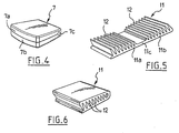
- the figure 4 shows a resiliently compressible cushion 7 foldable in one piece, with two parts 7a and 7b folded one over the other around a portion 7c which is a thinned area forming a folding hinge which will become the posterior end of the corner.
- the prosthesis is thus divided into two units cooperating with each other by complementary contact surfaces, here schematically planar.
- the cushion 11 shown also has two parts 11a and 11b foldable one over the other around a thinned zone 11c serving as folding hinge so that, as shown in FIG. figure 6 indentations 12 can interpenetrate when the two parts are folded over one another.
- the contact surface by which the two units of the prosthesis cooperate is here complex: it is the flanks of the teeth that interpenetrate.
- the indentations are curved, for example, in a circular arc centered on the side of the hinge.
- the two parts 11a and 11b can be separated (the hinge being removed) and simply superimposed with imbrication of their indentation.
- the prosthesis described above corresponds to a monobloc prosthesis which is put in place by means of an anterior access route.
- it will comprise two half prostheses which will be put in place by lateral access ways so as to laterally frame a portion (nucleus pulposus) remaining of the natural disk.
- the shape of each half prosthesis will be adapted to the morphology encountered being for example, seen from above, similar to a bean.
- Each half prosthesis will be divided into two units in the different variants described above.
Abstract
Description
L'invention concerne une prothèse selon le préambule de la revendication1. Ainsi, l'invention concerne une prothèse de disque intervertébral destinée à remplacer partiellement ou totalement les disques naturels assurant la liaison entre deux vertèbres de la colonne vertébrale, quelle que soit la partie concernée du rachis.The invention relates to a prosthesis according to the preamble of
On connaît une prothèse mentionnée ci-dessus, par exemple, de
Le traitement de ce type d'affection consiste à pratiquer l'ablation du disque malade et son remplacement soit par un élément mobile ou déformable soit par un élément qui relie rigidement les deux vertèbres concernées.The treatment of this type of affection consists in practicing the removal of the diseased disc and its replacement either by a movable or deformable element or by an element that rigidly connects the two vertebrae concerned.
Plusieurs types de prothèses ont été proposés pour remplacer le disque intervertébral mais elles ne sont que partiellement satisfaisantes. En effet, elles préservent la mobilité intervertébrale et restaure la distance intervertébrale à une valeur proche de celle assurée par un disque sain. En revanche elles imposent, dans cette mobilité, une cinématique particulière qui n'est pas compatible ou qui n'est que partiellement compatible avec la mobilité naturelle relative de deux vertèbres. La prothèse, dans la plupart des cas, impose une cinématique qui lui est propre, avec son centre de rotation et ses différents guidages plan sur plan, qui ne manque pas de venir en interférence avec les éléments de l'articulation naturelle qui demeurent entre deux vertèbres, notamment les facettes articulaires postérieures. Il faut noter à cet égard que le soin avec lequel on doigt poser la prothèse est important car toute imprécision dans ce placement augmente la gravité du conflit entre la cinématique de la prothèse et la cinématique naturelle. Cette mobilité non physiologique peut être à l'origine de conséquences cliniques indésirables. On peut même craindre des risques de migration d'un composant ou de luxation de l'articulation prothétique.Several types of prostheses have been proposed to replace the intervertebral disk but they are only partially satisfactory. Indeed, they preserve intervertebral mobility and restores the intervertebral distance to a value close to that provided by a healthy disc. On the other hand, they impose, in this mobility, a particular kinematics that is not compatible or only partially compatible with the relative natural mobility of two vertebrae. The prosthesis, in most cases, imposes a kinematics of its own, with its center of rotation and its various plane-to-plane guidance, which does not fail to come into interference with the elements of the natural joint that remain between two vertebrae, including the posterior articular facets. It should be noted in this regard that the care with which you put the prosthesis is important because any inaccuracy in this placement increases the severity of the conflict between the kinematics of the prosthesis and natural kinematics. This unphysiological mobility can cause undesirable clinical consequences. One can even fear risks of migration of a component or dislocation of the prosthetic joint.
De plus, pour la plupart d'entre elles, les prothèses connues ne sont pas de nature à restaurer la lordose cervicale ou lombaire normale. La restauration de la distance intervertébrale ne prend pas en compte l'inclinaison nécessaire d'une vertèbre à l'autre dans l'empilement qui conduit à cette lordose dont l'existence est utile à une biomécanique normale de l'ensemble du rachis, et plus particulièrement des étages adjacents.In addition, for most of them, known prostheses are not likely to restore normal cervical or lumbar lordosis. The restoration of the intervertebral distance does not take into account the necessary inclination of one vertebra to another in the stack which leads to this lordosis whose existence is useful to a normal biomechanics of the whole spine, and more particularly adjacent floors.
Par ailleurs, les prothèses connues ne sont pas adaptées à absorber les chocs. La conséquence de cette inaptitude, associée au conflit entre la cinématique naturelle et la cinématique de l'articulation, peut conduire à la production d'une usure prématurée, et des éléments naturels, et des éléments prothétiques, risquant de dégrader l'état clinique du patient.Moreover, known prostheses are not suitable for absorbing shocks. The consequence of this inaptitude, associated with the conflict between the natural kinematics and the kinematics of the joint, can lead to the production of premature wear, and natural elements, and prosthetic elements, which may degrade the clinical state of the joint. patient.
La présente invention entend remédier à ces inconvénients par une prothèse discale de structures simple et de pose facilitée.The present invention intends to overcome these disadvantages by a disc prosthesis of simple structures and easy installation.
À cet effet, la présente invention a pour objet une prothèse de disque intervertébral qui comporte :
- un plateau supérieur rigide,
- un plateau inférieur rigide,
- un coussin, intermédiaire élastiquement compressible, logé entre les surfaces internes des deux plateaux, caractérisée en ce que le coussin est divisé dans le sens de l'épaisseur en deux unités reposant l'une sur l'autre par des surfaces de contact complémentaires, et en ce que le coussin est un composant replié sur lui-même.
- a rigid top plate,
- a rigid lower plate,
- a cushion, elastically compressible intermediate, housed between the internal surfaces of the two trays, characterized in that the cushion is divided in the direction of the thickness into two units resting on each other by complementary contact surfaces, and in that the cushion is a folded component on itself.
Cette structure se présente sous la forme d'une pièce qui n'impose aux deux vertèbres qu'elle relie aucune liaison contrainte (bien entendu pour des amplitudes correspondant à un déplacement relatif naturel). Il s'ensuit que les guides naturels de ce déplacement relatif restent prépondérants (facettes articulaires postérieures notamment) et leur intégrité est préservée. En outre, au niveau de ces surfaces de contact, il est possible par le choix approprié de leur forme et de leur état, de maîtriser la nature et la concentration des contraintes ainsi que les déformations qui existeront à leur niveau.This structure is in the form of a part that does not impose on the two vertebrae that it connects any constrained connection (of course for amplitudes corresponding to a natural relative displacement). It follows that the natural guides of this relative displacement remain preponderant (posterior facet joints in particular) and their integrity is preserved. In addition, at the level of these contact surfaces, it is possible by the appropriate choice of their shape and their state, to control the nature and the concentration of the constraints as well as the deformations that will exist at their level.
Les surfaces de contact complémentaires seront, dans un premier mode de réalisation de l'invention, ménagée dans l'épaisseur même du coussin intermédiaire et de préférence sous la forme de creux et de bosses (dents), les bosses de l'une étant complémentaires des creux de l'autre de sorte qu'ils viennent en contact les unes avec les autres par au moins la surface de leurs flancs.The complementary contact surfaces will be, in a first embodiment of the invention, formed in the thickness of the intermediate cushion and preferably in the form of recesses and bumps (teeth), the bumps of one being complementary recesses of the other so that they come into contact with each other by at least the surface of their flanks.
Dans un mode de réalisation préféré de l'invention, le coussin intermédiaire élastiquement compressible, logé entre les deux surfaces internes des plateaux, possède à l'état libre, la forme générale d'un coin entre ces deux plateaux. Cette forme en coin de la structure permet de restaurer la lordose du rachis que la dégénérescence discale a en général détériorée.In a preferred embodiment of the invention, the elastically compressible intermediate cushion, housed between the two internal surfaces of the plates, has in the free state, the general shape of a wedge between these two plates. This shape in the corner of the structure helps restore lordosis of the spine that disc degeneration has generally deteriorated.
Le coussin est par exemple à base de polyéthylènes haute densité de polyuréthanes haute densité, de silicones ou de composites de ces différents matériaux.The cushion is for example based on high density polyethylenes high density polyurethanes, silicones or composites of these different materials.
La prothèse comporte de manière préférée une membrane de contention du coussin fixée aux plateaux. Cette membrane de contention permet d'éviter l'envahissement biologique et la colonisation de la prothèse. Il assure par ailleurs, bien que tous les matériaux utilisés soient biocompatibles, un isolement complet du coussin à l'égard du milieu biologique voisin et forme une barrière à la migration dans l'organisme d'éventuelles particules provenant du coussin.The prosthesis preferably comprises a membrane for restraining the cushion fixed to the plates. This compression membrane makes it possible to avoid biological invasion and colonization of the prosthesis. It also ensures, although all the materials used are biocompatible, a complete isolation of the cushion with respect to the surrounding biological medium and forms a barrier to the migration into the body of any particles from the cushion.
Cette membrane peut-être un anneau fixé aux plateaux (laissant un contact direct coussin-plateau), ou bien un sac hermétique, enfermant le coussin, et par exemple collé aux plateaux, ou encore une membrane prise en sandwich entre chaque plateau et une platine rivetée à celui-ci, l'autre face de cette platine étant en contact avec le coussin.This membrane may be a ring attached to the trays (leaving a direct cushion-tray contact), or an airtight bag, enclosing the cushion, and for example glued to the trays, or a membrane sandwiched between each tray and a platen riveted to it, the other face of this plate being in contact with the cushion.
D'autres dispositions constructives apparaîtront à la lecture de ce qui suit. On mentionnera en particulier l'existence d'un lien entre les deux plateaux de la prothèse qui permet de la maintenir dans un état comprimé afin d'en faciliter la pose. L'un des avantages de cette prothèse réside dans la pose aisée de celle-ci qui ne requiert pas une grande précision puisque elle n'impose pas de devoir « accorder » ses degrés de liberté avec ceux, naturels, existant entre deux vertèbres.Other constructive provisions will appear on reading the following. In particular, the existence of a link between the two trays of the prosthesis which makes it possible to keep it in a compressed state in order to facilitate its installation. One of the advantages of this prosthesis lies in the easy installation of this one which does not require a great precision since it does not impose a duty "to grant" its degrees of freedom with those, natural, existing between two vertebrae.
D'autres caractéristiques et avantages de l'invention ressortiront de la description donnée ci-après de quelques exemples de sa réalisation.Other features and advantages of the invention will emerge from the description given below of some examples of its implementation.
Il sera fait références aux dessins annexés parmi lesquels :
- la
figure 1 représente une prothèse selon l'invention placée entre deux vertèbres cervicales, - la
figure 2 est une vue éclatée d'une réalisation d'une prothèse conforme à l'invention, - la
figure 3 est une vue de la prothèse de lafigure 2 refermée et maintenue comprimée par un lien sécable, - la
figure 4 est une représentation d'un mode de réalisation du coussin compressible, - la
figure 5 est une représentation d'une variante de réalisation du coussin compressible de la figure précédente, - la
figure 6 est une représentation du coussin de la figure précédente refermé sur lui-même.
- the
figure 1 represents a prosthesis according to the invention placed between two cervical vertebrae, - the
figure 2 is an exploded view of an embodiment of a prosthesis according to the invention, - the
figure 3 is a view of the prosthesis of thefigure 2 closed and maintained compressed by a breakable link, - the
figure 4 is a representation of an embodiment of the compressible cushion, - the
figure 5 is a representation of an alternative embodiment of the compressible cushion of the previous figure, - the
figure 6 is a representation of the cushion of the previous figure closed on itself.
À la
Les plateaux 5 et 6 extrêmes de la prothèse sont au contact des corps vertébraux la et 2a par l'intermédiaire de surfaces préalablement préparées sur ces corps après ablation du disque naturel détérioré. La surface externe de ces plateaux peut comporter des moyens d'ancrage, par exemple des reliefs, pour améliorer la fixation à l'os ; il peut également s'agir de vis ou tout élément équivalente. On a représenté la lordose du rachis par l'angle A qu'impose la prothèse à l'orientation relative des deux vertèbres.The
À la
À la
On remarque sur cette figure que les plateaux 5 et 6 sont de dimensions telles qu'ils sont, dans la partie postérieure de la prothèse, en retrait du coussin, lequel déborde des plateaux par une partie 9 du côté de l'arête du coin.Note in this figure that the
La
À la
Dans une variante non représentée, les indentations sont courbes, par exemple,en arc de cercle centré du côté de la charnière.In a variant not shown, the indentations are curved, for example, in a circular arc centered on the side of the hinge.
Dans une autre variante non représentée, les deux parties 11a et 11b peuvent être séparées (la charnière étant supprimée) et simplement superposées avec imbrication de leur indentation.In another variant not shown, the two
De manière avantageuse, au moins l'un des plateaux 5 et 6 et de préférence les deux, est dimensionné de façon que la prothèse ait un coussin qui déborde des plateaux à l'arrière de celle-ci pour laisser un espace voisin de la partie postérieure du rachis dépourvu de tout élément métallique avec deux objectifs :
- limiter l'artefact (le brouillage de l'imagerie) de cette partie postérieure du rachis en éloignant de cette partie la partie métallique que constitue, le plateau,
- faciliter la décompression (résection des coins postérieurs des plateaux vertébraux).
- limit the artifact (the scrambling of imaging) of this posterior part of the spine by moving away from this part the metal part that constitutes, the plate,
- facilitate decompression (resection of the posterior corners of the vertebral trays).
On mentionnera enfin le fait que la prothèse ci-dessus décrite correspond à une prothèse monobloc qui est mise en place au moyen d'une voie d'accès antérieure. Dans un mode de réalisation adapté à une mise en place par une voie postérieure, elle comprendra deux demi prothèses qui seront mises en place par des voies d'accès latérales de manière à encadrer latéralement une partie (nucleus pulposus) restante du disque naturel. La forme de chaque demi prothèse sera adaptée à la morphologie rencontrée en étant par exemple, vue de dessus, semblable à un haricot. Chaque demi prothèse sera divisée en deux unités dans les différentes variantes décrites ci-dessus.Finally, mention should be made of the fact that the prosthesis described above corresponds to a monobloc prosthesis which is put in place by means of an anterior access route. In one embodiment adapted to implementation by a posterior route, it will comprise two half prostheses which will be put in place by lateral access ways so as to laterally frame a portion (nucleus pulposus) remaining of the natural disk. The shape of each half prosthesis will be adapted to the morphology encountered being for example, seen from above, similar to a bean. Each half prosthesis will be divided into two units in the different variants described above.
Claims (7)
- Intervertebral disk prosthesis (4), comprising:- a rigid upper plate (5),- a rigid lower plate (6),- an elastically compressible intermediate cushion (7) arranged between the two internal surfaces of the plates (5, 6), characterized in that the cushion is divided in the thickness direction into two units resting one upon the other by complementary contact surfaces, and in that the cushion (7) is a component folded up onto itself.
- Prosthesis according to claim 1, characterized in that it has, in the released condition, the general shape of a wedge between the two plates.
- Prosthesis according to any one of the preceding claims, characterized in that it comprises a membrane (8) for retaining the cushion (7), connected to the plates (5, 6).
- Prosthesis according to any one of the preceding claims, characterized in that it comprises a link (10) for maintaining the cushion in the compressed condition, capable of being cut after the prosthesis having been arranged in place.
- Prosthesis according to any one of the preceding claims, characterized in that the complementary contact surfaces of the two units are provided with nested indentations (12).
- Prosthesis according to any one of the preceding claims, characterized in that the cushion (7, 11) is made up of two portions (7a, 7b, 11a, 11b) which are connected by a reduced zone (7c, 11c) forming a folding hinge.
- Prosthesis according to any one of the preceding claims, characterized in that the plates (5, 6) are limited in their rear portion, the prosthesis thereby comprising a posterior cushion portion (9) protruding from said plates.
Applications Claiming Priority (2)
| Application Number | Priority Date | Filing Date | Title |
|---|---|---|---|
| FR0511596A FR2893248A1 (en) | 2005-11-16 | 2005-11-16 | INTERVERTEBRAL DISC PROSTHESIS |
| PCT/FR2006/002515 WO2007057555A1 (en) | 2005-11-16 | 2006-11-14 | Intervertebral disc prosthesis |
Publications (2)
| Publication Number | Publication Date |
|---|---|
| EP2032084A1 EP2032084A1 (en) | 2009-03-11 |
| EP2032084B1 true EP2032084B1 (en) | 2010-12-15 |
Family
ID=36950607
Family Applications (1)
| Application Number | Title | Priority Date | Filing Date |
|---|---|---|---|
| EP06831114A Expired - Fee Related EP2032084B1 (en) | 2005-11-16 | 2006-11-14 | Intervertebral disc prosthesis |
Country Status (9)
| Country | Link |
|---|---|
| US (1) | US8821577B2 (en) |
| EP (1) | EP2032084B1 (en) |
| JP (1) | JP4838319B2 (en) |
| KR (1) | KR20090005284A (en) |
| CN (1) | CN101484095A (en) |
| AU (1) | AU2006314365B9 (en) |
| DE (1) | DE602006019004D1 (en) |
| FR (1) | FR2893248A1 (en) |
| WO (1) | WO2007057555A1 (en) |
Families Citing this family (15)
| Publication number | Priority date | Publication date | Assignee | Title |
|---|---|---|---|---|
| FR2921820B1 (en) * | 2007-10-05 | 2011-09-16 | Vincent Pointillart | INTERVERTEBRAL PROSTHESIS |
| US20100042213A1 (en) | 2008-08-13 | 2010-02-18 | Nebosky Paul S | Drug delivery implants |
| US10842645B2 (en) | 2008-08-13 | 2020-11-24 | Smed-Ta/Td, Llc | Orthopaedic implant with porous structural member |
| WO2010019799A1 (en) * | 2008-08-13 | 2010-02-18 | Smed-Ta/Td, Llc | Orthopaedic implant with porous structural member |
| US9700431B2 (en) * | 2008-08-13 | 2017-07-11 | Smed-Ta/Td, Llc | Orthopaedic implant with porous structural member |
| US9616205B2 (en) | 2008-08-13 | 2017-04-11 | Smed-Ta/Td, Llc | Drug delivery implants |
| WO2010025386A1 (en) | 2008-08-29 | 2010-03-04 | Smed-Ta/Td, Llc | Orthopaedic implant |
| DE102009032220B4 (en) * | 2009-07-06 | 2018-04-12 | Getrag Getriebe- Und Zahnradfabrik Hermann Hagenmeyer Gmbh & Cie Kg | Powertrain monitoring method |
| US20110029085A1 (en) * | 2009-07-31 | 2011-02-03 | Warsaw Orthopedic, Inc. | Flexible spinal implant |
| US9700425B1 (en) | 2011-03-20 | 2017-07-11 | Nuvasive, Inc. | Vertebral body replacement and insertion methods |
| FR2974497A1 (en) | 2011-04-27 | 2012-11-02 | Centre Nat Rech Scient | INTERVERTEBRAL DISC PROSTHESIS IN THERMOPLASTIC MATERIAL WITH A GRADIENT OF MECHANICAL PROPERTIES |
| US9445919B2 (en) | 2011-12-19 | 2016-09-20 | Warsaw Orthopedic, Inc. | Expandable interbody implant and methods of use |
| JP7317461B2 (en) | 2017-08-22 | 2023-07-31 | 株式会社ダイヘン | tap changer |
| CN108670508A (en) * | 2018-06-15 | 2018-10-19 | 李伟明 | A kind of integral type artificial intervertebral disk |
| EP3979951A1 (en) * | 2019-06-10 | 2022-04-13 | Life Spine, Inc. | Expandable implant assembly with compression features |
Family Cites Families (17)
| Publication number | Priority date | Publication date | Assignee | Title |
|---|---|---|---|---|
| DE3911610A1 (en) * | 1989-04-08 | 1990-10-18 | Bosch Gmbh Robert | ARTIFICIAL DISC |
| JPH02307494A (en) * | 1989-05-23 | 1990-12-20 | Toyo Tire & Rubber Co Ltd | Manufacture of cushion body with upholstery |
| ATE141149T1 (en) * | 1992-04-21 | 1996-08-15 | Sulzer Medizinaltechnik Ag | ARTIFICIAL DISC BODY |
| GB9713330D0 (en) * | 1997-06-25 | 1997-08-27 | Bridport Gundry Plc | Surgical implant |
| FR2772594B1 (en) * | 1997-12-19 | 2000-05-05 | Henry Graf | REAR PARTIAL DISCAL PROSTHESIS |
| FR2787014B1 (en) * | 1998-12-11 | 2001-03-02 | Dimso Sa | INTERVERTEBRAL DISC PROSTHESIS WITH REDUCED FRICTION |
| US7008427B2 (en) * | 2000-05-25 | 2006-03-07 | Orthoplex, Llc | Inter-vertebral disc prosthesis for rachis through anterior surgery thereof |
| US6679914B1 (en) * | 2000-11-14 | 2004-01-20 | Shlomo Gabbay | Implantable orthopedic support apparatus |
| US20060089721A1 (en) * | 2001-01-17 | 2006-04-27 | Muhanna Nabil L | Intervertebral disc prosthesis and methods of implantation |
| US6726720B2 (en) * | 2002-03-27 | 2004-04-27 | Depuy Spine, Inc. | Modular disc prosthesis |
| WO2004016217A2 (en) * | 2002-08-15 | 2004-02-26 | David Gerber | Controlled artificial intervertebral disc implant |
| CA2499116A1 (en) * | 2002-09-18 | 2004-04-01 | Sdgi Holdings, Inc. | Natural tissue devices and methods of implantation |
| US20050015150A1 (en) * | 2003-07-17 | 2005-01-20 | Lee Casey K. | Intervertebral disk and nucleus prosthesis |
| US7250060B2 (en) | 2004-01-27 | 2007-07-31 | Sdgi Holdings, Inc. | Hybrid intervertebral disc system |
| EP2641571B1 (en) | 2004-06-30 | 2016-04-13 | Synergy Disc Replacement Inc. | Artificial spinal disc |
| US20060069436A1 (en) * | 2004-09-30 | 2006-03-30 | Depuy Spine, Inc. | Trial disk implant |
| US7905922B2 (en) * | 2006-12-20 | 2011-03-15 | Zimmer Spine, Inc. | Surgical implant suitable for replacement of an intervertebral disc |
-
2005
- 2005-11-16 FR FR0511596A patent/FR2893248A1/en not_active Withdrawn
-
2006
- 2006-11-14 KR KR1020087014467A patent/KR20090005284A/en active IP Right Grant
- 2006-11-14 CN CNA2006800491100A patent/CN101484095A/en active Pending
- 2006-11-14 AU AU2006314365A patent/AU2006314365B9/en not_active Ceased
- 2006-11-14 JP JP2008540650A patent/JP4838319B2/en not_active Expired - Fee Related
- 2006-11-14 WO PCT/FR2006/002515 patent/WO2007057555A1/en active Application Filing
- 2006-11-14 DE DE602006019004T patent/DE602006019004D1/en active Active
- 2006-11-14 US US12/093,845 patent/US8821577B2/en not_active Expired - Fee Related
- 2006-11-14 EP EP06831114A patent/EP2032084B1/en not_active Expired - Fee Related
Also Published As
| Publication number | Publication date |
|---|---|
| CN101484095A (en) | 2009-07-15 |
| FR2893248A1 (en) | 2007-05-18 |
| EP2032084A1 (en) | 2009-03-11 |
| AU2006314365B9 (en) | 2010-07-22 |
| KR20090005284A (en) | 2009-01-13 |
| US8821577B2 (en) | 2014-09-02 |
| AU2006314365A1 (en) | 2007-05-24 |
| AU2006314365B2 (en) | 2010-07-15 |
| JP2009515625A (en) | 2009-04-16 |
| WO2007057555A1 (en) | 2007-05-24 |
| US20090228109A1 (en) | 2009-09-10 |
| DE602006019004D1 (en) | 2011-01-27 |
| JP4838319B2 (en) | 2011-12-14 |
Similar Documents
| Publication | Publication Date | Title |
|---|---|---|
| EP2032084B1 (en) | Intervertebral disc prosthesis | |
| EP1981443B1 (en) | Anatomic intervertebral spacer | |
| EP1137377B1 (en) | Intervetebral disc prosthesis with contact blocks | |
| EP1263352B1 (en) | Disc prosthesis for cervical vertebra | |
| WO1994004100A1 (en) | Intervertebral disk prosthesis | |
| WO2005053579A1 (en) | Postero-lateral intervertebral disc prosthesis | |
| WO2005046534A1 (en) | Total intervertebral-disc prothesis | |
| EP2765956B1 (en) | Intersomatic implant | |
| FR2909860A1 (en) | Partial or total intervertebral disk articular prosthesis for use in orthopedic surgery, has upper and lower articular surfaces respectively tapered at pole by other surfaces delimiting mobility space between them | |
| EP1696837B1 (en) | Intervertebral disc prosthesis | |
| EP2200541B1 (en) | Intervertebral prosthesis | |
| EP2349113A2 (en) | Self-adjusting and self-stabilizing intervertebral disc prosthesis | |
| EP2398423B1 (en) | Intervertebral disc prosthesis | |
| EP1706076B1 (en) | Intervertebral discal prosthesis | |
| FR2744627A1 (en) | Prosthesis for restoring articulation between two bones, e.g. intervertebral prosthesis | |
| EP2677970B1 (en) | Intervertebral-disc prosthesis | |
| FR2856916A1 (en) | Knee joint prosthesis has a tibia plate fixed at the upper end of the tibia, and a femur section anchored at the lower end of the femur with three zones of different curvatures and studs of a different thickness | |
| FR3083074A1 (en) | IMPLANTABLE DEVICE FOR MELTING TWO ADJACENT VERTEBRES |
Legal Events
| Date | Code | Title | Description |
|---|---|---|---|
| PUAI | Public reference made under article 153(3) epc to a published international application that has entered the european phase |
Free format text: ORIGINAL CODE: 0009012 |
|
| 17P | Request for examination filed |
Effective date: 20080613 |
|
| AK | Designated contracting states |
Kind code of ref document: A1 Designated state(s): DE FR |
|
| RAP1 | Party data changed (applicant data changed or rights of an application transferred) |
Owner name: WARSAW ORTHOPEDIC, INC. |
|
| RIN1 | Information on inventor provided before grant (corrected) |
Inventor name: ASSAKER, RICHARD Inventor name: POINTILLART, VINCENT |
|
| GRAP | Despatch of communication of intention to grant a patent |
Free format text: ORIGINAL CODE: EPIDOSNIGR1 |
|
| GRAS | Grant fee paid |
Free format text: ORIGINAL CODE: EPIDOSNIGR3 |
|
| GRAA | (expected) grant |
Free format text: ORIGINAL CODE: 0009210 |
|
| AK | Designated contracting states |
Kind code of ref document: B1 Designated state(s): DE FR |
|
| REF | Corresponds to: |
Ref document number: 602006019004 Country of ref document: DE Date of ref document: 20110127 Kind code of ref document: P |
|
| PLBE | No opposition filed within time limit |
Free format text: ORIGINAL CODE: 0009261 |
|
| STAA | Information on the status of an ep patent application or granted ep patent |
Free format text: STATUS: NO OPPOSITION FILED WITHIN TIME LIMIT |
|
| 26N | No opposition filed |
Effective date: 20110916 |
|
| REG | Reference to a national code |
Ref country code: DE Ref legal event code: R097 Ref document number: 602006019004 Country of ref document: DE Effective date: 20110916 |
|
| REG | Reference to a national code |
Ref country code: DE Ref legal event code: R082 Ref document number: 602006019004 Country of ref document: DE Representative=s name: PATENTANWAELTE SCHAUMBURG, THOENES, THURN, LAN, DE |
|
| REG | Reference to a national code |
Ref country code: DE Ref legal event code: R081 Ref document number: 602006019004 Country of ref document: DE Owner name: ASSAKER, RICHARD, DR., BE Free format text: FORMER OWNER: WARSAW ORTHOPEDIC, INC., WARSAW, US Effective date: 20130813 Ref country code: DE Ref legal event code: R082 Ref document number: 602006019004 Country of ref document: DE Representative=s name: PATENTANWAELTE SCHAUMBURG, THOENES, THURN, LAN, DE Effective date: 20130813 Ref country code: DE Ref legal event code: R081 Ref document number: 602006019004 Country of ref document: DE Owner name: POINTILLART, VINCENT, DR., FR Free format text: FORMER OWNER: WARSAW ORTHOPEDIC, INC., WARSAW, US Effective date: 20130813 Ref country code: DE Ref legal event code: R081 Ref document number: 602006019004 Country of ref document: DE Owner name: POINTILLART, VINCENT, DR., FR Free format text: FORMER OWNER: WARSAW ORTHOPEDIC, INC., WARSAW, IND., US Effective date: 20130813 Ref country code: DE Ref legal event code: R081 Ref document number: 602006019004 Country of ref document: DE Owner name: ASSAKER, RICHARD, DR., BE Free format text: FORMER OWNER: WARSAW ORTHOPEDIC, INC., WARSAW, IND., US Effective date: 20130813 Ref country code: DE Ref legal event code: R082 Ref document number: 602006019004 Country of ref document: DE Representative=s name: SCHAUMBURG & PARTNER PATENTANWAELTE GBR, DE Effective date: 20130813 Ref country code: DE Ref legal event code: R082 Ref document number: 602006019004 Country of ref document: DE Representative=s name: SCHAUMBURG & PARTNER PATENTANWAELTE MBB, DE Effective date: 20130813 Ref country code: DE Ref legal event code: R082 Ref document number: 602006019004 Country of ref document: DE Representative=s name: SCHAUMBURG UND PARTNER PATENTANWAELTE MBB, DE Effective date: 20130813 |
|
| REG | Reference to a national code |
Ref country code: FR Ref legal event code: TQ Owner name: RICHARD ASSAKER, BE Effective date: 20130930 Ref country code: FR Ref legal event code: TQ Owner name: POINTILLART, VINCENT, FR Effective date: 20130930 |
|
| REG | Reference to a national code |
Ref country code: DE Ref legal event code: R082 Ref document number: 602006019004 Country of ref document: DE Representative=s name: SCHAUMBURG & PARTNER PATENTANWAELTE GBR, DE Ref country code: DE Ref legal event code: R082 Ref document number: 602006019004 Country of ref document: DE Representative=s name: SCHAUMBURG & PARTNER PATENTANWAELTE MBB, DE Ref country code: DE Ref legal event code: R082 Ref document number: 602006019004 Country of ref document: DE Representative=s name: SCHAUMBURG UND PARTNER PATENTANWAELTE MBB, DE |
|
| REG | Reference to a national code |
Ref country code: FR Ref legal event code: PLFP Year of fee payment: 10 |
|
| PGFP | Annual fee paid to national office [announced via postgrant information from national office to epo] |
Ref country code: FR Payment date: 20151119 Year of fee payment: 10 |
|
| PGFP | Annual fee paid to national office [announced via postgrant information from national office to epo] |
Ref country code: DE Payment date: 20161121 Year of fee payment: 11 |
|
| REG | Reference to a national code |
Ref country code: FR Ref legal event code: ST Effective date: 20170731 |
|
| PG25 | Lapsed in a contracting state [announced via postgrant information from national office to epo] |
Ref country code: FR Free format text: LAPSE BECAUSE OF NON-PAYMENT OF DUE FEES Effective date: 20161130 |
|
| REG | Reference to a national code |
Ref country code: DE Ref legal event code: R119 Ref document number: 602006019004 Country of ref document: DE |
|
| PG25 | Lapsed in a contracting state [announced via postgrant information from national office to epo] |
Ref country code: DE Free format text: LAPSE BECAUSE OF NON-PAYMENT OF DUE FEES Effective date: 20180602 |