EP2031615A2 - Clockwise and counterclockwise rotation switching device for power tool - Google Patents
Clockwise and counterclockwise rotation switching device for power tool Download PDFInfo
- Publication number
- EP2031615A2 EP2031615A2 EP20080013471 EP08013471A EP2031615A2 EP 2031615 A2 EP2031615 A2 EP 2031615A2 EP 20080013471 EP20080013471 EP 20080013471 EP 08013471 A EP08013471 A EP 08013471A EP 2031615 A2 EP2031615 A2 EP 2031615A2
- Authority
- EP
- European Patent Office
- Prior art keywords
- clockwise
- switching device
- counterclockwise rotation
- power tool
- unit base
- Prior art date
- Legal status (The legal status is an assumption and is not a legal conclusion. Google has not performed a legal analysis and makes no representation as to the accuracy of the status listed.)
- Withdrawn
Links
- 230000033228 biological regulation Effects 0.000 claims abstract description 37
- 230000002093 peripheral effect Effects 0.000 claims description 19
- 238000003780 insertion Methods 0.000 claims description 3
- 230000037431 insertion Effects 0.000 claims description 3
- 244000145845 chattering Species 0.000 abstract description 11
- 230000007423 decrease Effects 0.000 description 5
- OKTJSMMVPCPJKN-UHFFFAOYSA-N Carbon Chemical compound [C] OKTJSMMVPCPJKN-UHFFFAOYSA-N 0.000 description 2
- 238000005452 bending Methods 0.000 description 2
- 229910052799 carbon Inorganic materials 0.000 description 2
- 230000000694 effects Effects 0.000 description 2
- 238000000034 method Methods 0.000 description 2
- 230000007935 neutral effect Effects 0.000 description 2
- 230000001105 regulatory effect Effects 0.000 description 2
- 239000000463 material Substances 0.000 description 1
- 229910052751 metal Inorganic materials 0.000 description 1
- 239000002184 metal Substances 0.000 description 1
- 150000002739 metals Chemical group 0.000 description 1
- 229920005989 resin Polymers 0.000 description 1
- 239000011347 resin Substances 0.000 description 1
- 229920003002 synthetic resin Polymers 0.000 description 1
- 239000000057 synthetic resin Substances 0.000 description 1
Images




Classifications
-
- H—ELECTRICITY
- H02—GENERATION; CONVERSION OR DISTRIBUTION OF ELECTRIC POWER
- H02K—DYNAMO-ELECTRIC MACHINES
- H02K23/00—DC commutator motors or generators having mechanical commutator; Universal AC/DC commutator motors
- H02K23/66—Structural association with auxiliary electric devices influencing the characteristic of, or controlling, the machine, e.g. with impedances or switches
-
- H—ELECTRICITY
- H01—ELECTRIC ELEMENTS
- H01H—ELECTRIC SWITCHES; RELAYS; SELECTORS; EMERGENCY PROTECTIVE DEVICES
- H01H9/00—Details of switching devices, not covered by groups H01H1/00 - H01H7/00
- H01H9/02—Bases, casings, or covers
- H01H9/06—Casing of switch constituted by a handle serving a purpose other than the actuation of the switch, e.g. by the handle of a vacuum cleaner
- H01H9/063—Casing of switch constituted by a handle serving a purpose other than the actuation of the switch, e.g. by the handle of a vacuum cleaner enclosing a reversing switch
-
- H—ELECTRICITY
- H02—GENERATION; CONVERSION OR DISTRIBUTION OF ELECTRIC POWER
- H02K—DYNAMO-ELECTRIC MACHINES
- H02K23/00—DC commutator motors or generators having mechanical commutator; Universal AC/DC commutator motors
- H02K23/02—DC commutator motors or generators having mechanical commutator; Universal AC/DC commutator motors characterised by arrangement for exciting
- H02K23/18—DC commutator motors or generators having mechanical commutator; Universal AC/DC commutator motors characterised by arrangement for exciting having displaceable main or auxiliary brushes
-
- H—ELECTRICITY
- H02—GENERATION; CONVERSION OR DISTRIBUTION OF ELECTRIC POWER
- H02K—DYNAMO-ELECTRIC MACHINES
- H02K5/00—Casings; Enclosures; Supports
- H02K5/04—Casings or enclosures characterised by the shape, form or construction thereof
- H02K5/14—Means for supporting or protecting brushes or brush holders
- H02K5/143—Means for supporting or protecting brushes or brush holders for cooperation with commutators
- H02K5/148—Slidably supported brushes
Definitions
- the present invention relates to a clockwise and counterclockwise rotation switching device provided on a motor-driven power tool for switching a rotation direction of a motor.
- a clockwise and counterclockwise rotation switching device for a power tool includes a unit base being fixed to a stator of a motor in a housing and having a pair of fixed contacts electrically connected with a coil of the stator, respectively, and a ring-shaped brush base holding a pair of carbon brushes, which face a commutator with the surface thereof in sliding contact with the commutator, and being rotatably attached to the unit base.
- a pair of movable contacts is provided between the fixed contacts in the brush base, respectively. Clockwise or counterclockwise rotation of the motor can be selected by switching a contact mode of both the movable contacts with respect to the fixed contacts, the switching being caused by a rotating operation of the brush base (for example, refer to patent document 1).
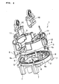
- Fig. 6 is a resolved perspective view to illustrate a particular example of a clockwise and counterclockwise rotation switching device.
- Fig. 7 is an assembled perspective view of the device.
- a disk-ring shaped unit base 2 is fixed to a stator of a motor, and a short sleeve shaped brush base 3 is coaxially attached at an upper part of the unit base 2 and has the approximately same diameter as that of the unit base 2.
- Both the unit base 2 and the brush base 3 are made of a synthetic resin.
- the unit base 2 includes a pair of circular-shaped fixed contacts 4 and 4 in a plane view in a point symmetric manner.
- An end part of the each fixed contact 4 mutually faces the other fixed contact with a predetermined interval therebetween in a peripheral direction, and serves also as elastic end 4a being movable in a radius direction.
- An insertion piece 5 is continuously connected with each fixed contact 4 and inserted into one pair of terminals on a coil side of the stator so as to be electrically connected.
- Lower ends of terminal metals 6 and 6 are inserted into the other pair of terminals on the coil side and upper ends thereof are connected with a switch.
- Connection parts 7, 7, connected to the terminal end of the stator with holding the insertion piece 5 and the terminal fitting 6 are formed at a lower side of the unit base 2.
- a pair of hooks 8 and 8 is upwardly projected at an inner periphery of the unit base 2. An upper end of each of the hooks 8 and 8 is outwardly folded.
- the hook 8 is engaged with recessed parts 9 and 9 formed in the peripheral direction on an inner periphery of the brush base 3, so that the brush base 3 is rotatably connected on the unit base 2.
- the brush base 3 is equipped with square sleeve shaped metallic brush holders 10 and 10 on a straight line at positions of point symmetry.
- the brush holder 10 can hold a carbon brush (not illustrated) mounted thereon.
- each brush holder 10 is connected with movable contacts 11 and 11 lower ends of which project and abut with lower ends of the brush base 3 at the point symmetry positions of the brush base 3.
- Each movable contact 11 is projected between the fixed contacts 4 and 4 of the unit base 2.
- Fig. 8 illustrates a neutral state in which the movable contacts 11 and 11 are not contacted with any fixed contact 4.
- the brush base 3 has operation projections 12 and 12 on the side thereof, and each operation projections 12 is outwardly projected through a window formed on the side of the housing of the power tool. The operation projections 12 and 12 enable the brush base 3 to be rotationally operated from an external of the housing.
- the fixed contact 4 has the elastic end 4a as an end part thereof, a contact pressure between the fixed contact 4 and an opposing movable contact 11 can be adjusted by the elastic property of the elastic end 4a.
- the elastic end 4a is used at an approximately upper limit in an elastic region in order to increase the contact pressure, the elastic end 4a is plastic-deformed because of influences of heat and vibration, so that the contact pressure decreases and the elastic end 4a may be chattered or fused.
- An object of the present invention is to provide a clockwise and counterclockwise rotation switching device for a power tool, which has a simple structure, can effectively suppress chattering or fusing of an elastic end due to decrease in a contact pressure, and can improve contact durability.
- a first aspect of the preset invention provides a clockwise and counterclockwise rotation switching device for a power tool which can select clockwise rotation or counterclockwise rotation of a motor.
- the clockwise and counterclockwise rotation switching device includes a unit base being fixed in a housing of the power tool and having a pair of fixed contacts connected with a coil of a motor, and a brush base rotatably provided to the unit base while holding a brush of the motor, having a pair of movable contacts positioned between the fixed contacts, and switching a contacting mode of the movable contact with respect to the fixed contact by a rotating operation.
- An end part of any one of contacts of the fixed contact and the movable contact is formed to be an elastic end which deforms in contact with another contact.
- the unit base or the brush base includes a regulation part regulating a deformation quantity of the elastic end which deforms upon the fixed contact being contacted with the movable contact, by abutting the elastic end.
- the regulation part has elasticity so as to deform upon abutting to the elastic end.
- the present invention it is possible to improve contact durability by preventing the decrease of a contact pressure of an elastic end with respect to heat and vibration, whereby suppressing chattering or fusing effectively. Particularly, this effect can be obtained with a simple structure in which a regulation part is provided. Thus, an increase in cost can be minimized.
- the regulation part has elasticity, a problem due to dimensional tolerance does not occur, and a space between the regulation part and the elastic end is not formed. Therefore, chattering or fusing of the elastic end can be suppressed more accurately.
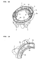
- Fig. 1 illustrates a unit base 2a (in a state where fixed contacts are not mounted) used for a clockwise and counterclockwise rotation switching device of the present invention, wherein Fig. 1A is a perspective view, and Fig. 1B is a partial enlarged view, respectively.
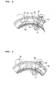
- Fig. 2 illustrates a unit base 2a having fixed contacts mounted thereon, wherein Fig. 2A is a plane view, and Fig. 2B is a partial enlarged view.
- the unit base 2a has the same main structure as that of the unit base 2 described in Figs. 6 to 8 .
- the unit base 2a has a pair of circular-shaped fixed contacts 4 and 4 in a plane view in a point symmetric manner.
- the unit base 2a includes a regulation projection 14 having an L shape in a plane view and being provided in a protruding condition as a regulation part on the outer peripheral side of each elastic end 4a of an elastic contact 4 on a bottom plate 13.
- the regulation projection 14 is abutted with the elastic end 4a, which is bent toward the outer peripheral side, so that the regulation projection 14 regulates the movement of the elastic end 4a to the more outer peripheral side.
- a brush base 3 has the same constitution as that described in Figs. 6 to 8 .
- the movable contacts 11 and 11 are moved in the peripheral direction, and contact with the elastic end 4a with outwardly bending the elastic end 4a of the fixed contacts 4 and 4 toward the outer peripheral side as illustrated in Fig. 2 .
- the elastic end 4a bent toward the outer peripheral side abuts with the regulation projection 14 to regulate more deformation.
- an end part of the fixed contact 4 is formed to be the elastic end 4a which is deformed upon contacting with the movable contact 11.
- the unit base 2a includes the regulation projection 14 regulating a deformation quantity by abutting to the elastic end 4a which is deformed upon the fixed contact 4 being contacted with the movable contact 11. Therefore, it can be prevented to decrease a contact pressure of the elastic end 4a with respect to heat or vibration, so that chattering or fusing is effectively suppressed, and thus the contact durability can be improved. Particularly, this effect can be obtained with a simple structure in which the regulation part 14 is provided. Thus, increase in cost can be minimized.
- Fig. 3 also illustrates the unit base 2b not having fixed contacts, wherein Fig. 3A is a perspective view, and Fig. 3B is a partial enlarged view.
- the unit base 2b includes a punched hole 15 at a top end of the regulation projection 14 in the bottom plate 13 so as to give elasticity to the top end of the regulation projection 14.
- clockwise and counterclockwise switching device when the brush base 3 is rotated to the clockwise rotation position, the movable contact 11 is contacted with the elastic end 4a of the fixed contact 4, and the elastic end 4a is bent toward the outer peripheral side to abut with the regulation projection 14. Then, as illustrated in Fig. 4 , a lower end of the regulation projection 14 is bent toward the outer peripheral side by its elasticity to press the elastic end 4a to the movable contact 11 side. Therefore, when heat or vibration is generated in conjunction with driving of the motor, chattering of the elastic end 4a on the outer peripheral side is suppressed, and thus a contacting state with the movable contact 11 is maintained. This operation is also carried out when the brush base 3 is rotated to a counterclockwise rotation position.
- the embodiment 2 can more reliably suppress chattering or fusing of the elastic end 4a than the embodiment 1.
- a shape of a regulation part is not limited in an L-shaped regulation projection as described above.
- the shape can be properly changed as long as it can regulate the deformation quantity of an elastic end.
- the regulation part can be a regulation projection 16 which is a wall along the radius direction as illustrated in Fig. 5 , a wall along the peripheral direction, or a circular projection.
- a method to give elasticity to the regulation part is not limited to a method to form a punched hole.
- the regulation part can have elasticity by changing a thickness of a wall.
- the regulation part is not limited to be integrally formed with the unit base, and can be a resin or metallic plate material or a plate spring which is separated from the unit base.
- the elastic end is deformed toward the outer periphery side.
- chattering or fusing of the elastic end can be similarly prevent by providing the regulation part on the inner periphery side.
- both the ends of the fixed contact on the unit base side are formed to be elastic ends and bent by abutting to the movable contact, which does not have an elastic end, on the brush base side.
- both ends of the movable contact on the brush base side can be formed to be elastic ends, and can be bent by abutting to the fixed contact, which does not have an elastic end, on the unit base side.
- the regulation part is provided on the lower face side of the brush base.
- the present invention can be used for a power tool having a switching function for a clockwise or counterclockwise rotation direction of a motor such as a motor-driven drill, a motor-driven driver drill or a motor-driven driver.
Landscapes
- Engineering & Computer Science (AREA)
- Power Engineering (AREA)
- Motor Or Generator Current Collectors (AREA)
- Motor Or Generator Frames (AREA)
- Portable Power Tools In General (AREA)
- Rotary Switch, Piano Key Switch, And Lever Switch (AREA)
Abstract
Description
- The present invention relates to a clockwise and counterclockwise rotation switching device provided on a motor-driven power tool for switching a rotation direction of a motor.
- A clockwise and counterclockwise rotation switching device for a power tool includes a unit base being fixed to a stator of a motor in a housing and having a pair of fixed contacts electrically connected with a coil of the stator, respectively, and a ring-shaped brush base holding a pair of carbon brushes, which face a commutator with the surface thereof in sliding contact with the commutator, and being rotatably attached to the unit base. A pair of movable contacts is provided between the fixed contacts in the brush base, respectively. Clockwise or counterclockwise rotation of the motor can be selected by switching a contact mode of both the movable contacts with respect to the fixed contacts, the switching being caused by a rotating operation of the brush base (for example, refer to patent document 1).
-
Fig. 6 is a resolved perspective view to illustrate a particular example of a clockwise and counterclockwise rotation switching device.Fig. 7 is an assembled perspective view of the device. In a clockwise and counterclockwise switching device 1, a disk-ringshaped unit base 2 is fixed to a stator of a motor, and a short sleeve shapedbrush base 3 is coaxially attached at an upper part of theunit base 2 and has the approximately same diameter as that of theunit base 2. Both theunit base 2 and thebrush base 3 are made of a synthetic resin. - The
unit base 2 includes a pair of circular-shapedfixed contacts contact 4 mutually faces the other fixed contact with a predetermined interval therebetween in a peripheral direction, and serves also aselastic end 4a being movable in a radius direction. Aninsertion piece 5 is continuously connected with eachfixed contact 4 and inserted into one pair of terminals on a coil side of the stator so as to be electrically connected. Lower ends ofterminal metals Connection parts insertion piece 5 and theterminal fitting 6 are formed at a lower side of theunit base 2. Further, a pair ofhooks unit base 2. An upper end of each of thehooks hook 8 is engaged withrecessed parts brush base 3, so that thebrush base 3 is rotatably connected on theunit base 2. - Then, the
brush base 3 is equipped with square sleeve shapedmetallic brush holders brush holder 10 can hold a carbon brush (not illustrated) mounted thereon. Further, as illustrated inFig. 8 , eachbrush holder 10 is connected withmovable contacts brush base 3 at the point symmetry positions of thebrush base 3. Eachmovable contact 11 is projected between thefixed contacts unit base 2. - Therefore, when the
movable contacts brush base 3, themovable contacts elastic ends fixed contacts elastic end 4a while outwardly bending theelastic end 4a on the outer periphery side. Then, the clockwise and counterclockwise rotation of the motor is switched. In addition,Fig. 8 illustrates a neutral state in which themovable contacts contact 4. Further, thebrush base 3 hasoperation projections operation projections 12 is outwardly projected through a window formed on the side of the housing of the power tool. Theoperation projections brush base 3 to be rotationally operated from an external of the housing. - Patent document 1: Japanese Unexamined Patent Publication No.
2003-180054 - When the fixed
contact 4 has theelastic end 4a as an end part thereof, a contact pressure between the fixedcontact 4 and an opposingmovable contact 11 can be adjusted by the elastic property of theelastic end 4a. However, when theelastic end 4a is used at an approximately upper limit in an elastic region in order to increase the contact pressure, theelastic end 4a is plastic-deformed because of influences of heat and vibration, so that the contact pressure decreases and theelastic end 4a may be chattered or fused. - An object of the present invention is to provide a clockwise and counterclockwise rotation switching device for a power tool, which has a simple structure, can effectively suppress chattering or fusing of an elastic end due to decrease in a contact pressure, and can improve contact durability.
- In order to achieve the above-described object, a first aspect of the preset invention provides a clockwise and counterclockwise rotation switching device for a power tool which can select clockwise rotation or counterclockwise rotation of a motor. The clockwise and counterclockwise rotation switching device includes a unit base being fixed in a housing of the power tool and having a pair of fixed contacts connected with a coil of a motor, and a brush base rotatably provided to the unit base while holding a brush of the motor, having a pair of movable contacts positioned between the fixed contacts, and switching a contacting mode of the movable contact with respect to the fixed contact by a rotating operation. An end part of any one of contacts of the fixed contact and the movable contact is formed to be an elastic end which deforms in contact with another contact. The unit base or the brush base includes a regulation part regulating a deformation quantity of the elastic end which deforms upon the fixed contact being contacted with the movable contact, by abutting the elastic end.
- In order to prevent chattering of the elastic end more reliably, it is preferable that the regulation part has elasticity so as to deform upon abutting to the elastic end.
- According to the present invention, it is possible to improve contact durability by preventing the decrease of a contact pressure of an elastic end with respect to heat and vibration, whereby suppressing chattering or fusing effectively. Particularly, this effect can be obtained with a simple structure in which a regulation part is provided. Thus, an increase in cost can be minimized.
- Further, when the regulation part has elasticity, a problem due to dimensional tolerance does not occur, and a space between the regulation part and the elastic end is not formed. Therefore, chattering or fusing of the elastic end can be suppressed more accurately.
-
-
Fig. 1 illustrates a unit base of a clockwise and counterclockwise rotation switching device of an embodiment 1, whereinFig. 1A is a perspective view, andFig. 1B is a partial enlarged view; -
Fig. 2 illustrates a unit base having fixed contacts, whereinFig. 2A is a plane view, andFig. 2B is a partial enlarged view; -
Fig. 3 illustrates a unit base of a clockwise and counterclockwise rotation switching device of anembodiment 2,Fig. 3A is a perspective view, andFig. 3B is a partial enlarged view; -
Fig. 4 is a partial enlarged view of a unit base in which contacts are contacted; -
Fig. 5 is a partial enlarged view of a unit base of a varied example; -
Fig. 6 is a resolved perspective view of a conventional clockwise and counterclockwise rotation switching device; -
Fig. 7 is a perspective view of the conventional clockwise and counterclockwise rotation switching device; and -
Fig. 8 illustrates a unit base so as to collectively illustrate movable contacts, whereinFig. 8A is a plane view, andFig. 8B is an enlarged view of a B part. - Embodiments of the present invention will be described below referring to the drawings. However, a basic structure of a clockwise and counterclockwise rotation switching device is similar to a conventional structure described in
Figs. 6 to 8 . Thus, the same numerals are used to the same constitutional parts so as to omit the descriptions, and different constitutional parts from those of a conventional structure will be mainly described. -
Fig. 1 illustrates aunit base 2a (in a state where fixed contacts are not mounted) used for a clockwise and counterclockwise rotation switching device of the present invention, whereinFig. 1A is a perspective view, andFig. 1B is a partial enlarged view, respectively. Further,Fig. 2 illustrates aunit base 2a having fixed contacts mounted thereon, whereinFig. 2A is a plane view, andFig. 2B is a partial enlarged view. Theunit base 2a has the same main structure as that of theunit base 2 described inFigs. 6 to 8 . For example, theunit base 2a has a pair of circular-shapedfixed contacts unit base 2a includes aregulation projection 14 having an L shape in a plane view and being provided in a protruding condition as a regulation part on the outer peripheral side of eachelastic end 4a of anelastic contact 4 on abottom plate 13. When amovable contact 11 is moved and contacted with theelastic end 4a, theregulation projection 14 is abutted with theelastic end 4a, which is bent toward the outer peripheral side, so that theregulation projection 14 regulates the movement of theelastic end 4a to the more outer peripheral side. Abrush base 3 has the same constitution as that described inFigs. 6 to 8 . - According to the clockwise and counterclockwise rotation switching device having the above-described constitution, when the
brush base 3 is rotated from a neutral position of themovable contacts movable contacts elastic end 4a with outwardly bending theelastic end 4a of the fixedcontacts Fig. 2 . In this state, theelastic end 4a bent toward the outer peripheral side abuts with theregulation projection 14 to regulate more deformation. Thus, when heat or vibration are generated in conjunction with driving of a motor, chattering of theelastic end 4a toward the outer side is suppressed, and a contacting state with themovable contacts brush base 3 is rotated to a counterclockwise rotation position. - Thus, according to the clockwise and counterclockwise rotation switching device in the above-described embodiment 1, an end part of the fixed
contact 4 is formed to be theelastic end 4a which is deformed upon contacting with themovable contact 11. Further, theunit base 2a includes theregulation projection 14 regulating a deformation quantity by abutting to theelastic end 4a which is deformed upon the fixedcontact 4 being contacted with themovable contact 11. Therefore, it can be prevented to decrease a contact pressure of theelastic end 4a with respect to heat or vibration, so that chattering or fusing is effectively suppressed, and thus the contact durability can be improved. Particularly, this effect can be obtained with a simple structure in which theregulation part 14 is provided. Thus, increase in cost can be minimized. -
Fig. 3 also illustrates theunit base 2b not having fixed contacts, whereinFig. 3A is a perspective view, andFig. 3B is a partial enlarged view. Theunit base 2b includes a punchedhole 15 at a top end of theregulation projection 14 in thebottom plate 13 so as to give elasticity to the top end of theregulation projection 14. - According to the present invention, clockwise and counterclockwise switching device, when the
brush base 3 is rotated to the clockwise rotation position, themovable contact 11 is contacted with theelastic end 4a of the fixedcontact 4, and theelastic end 4a is bent toward the outer peripheral side to abut with theregulation projection 14. Then, as illustrated inFig. 4 , a lower end of theregulation projection 14 is bent toward the outer peripheral side by its elasticity to press theelastic end 4a to themovable contact 11 side. Therefore, when heat or vibration is generated in conjunction with driving of the motor, chattering of theelastic end 4a on the outer peripheral side is suppressed, and thus a contacting state with themovable contact 11 is maintained. This operation is also carried out when thebrush base 3 is rotated to a counterclockwise rotation position. - Accordingly, in the clockwise and counterclockwise rotation switching device in the above-described
embodiment 2, it can be prevented to decrease a contact pressure of theelastic end 4a with respect to heat or vibration, so that chattering or fusing is effectively suppressed, and thus the contact durability can be improved with a simple structure in which theregulation projection 14 is provided. Particularly, theregulation projection 14 has elasticity so as to be deformed by abutting theelastic end 4a, a problem due to dimensional tolerance does not occur, and a space between theregulation projection 14 and theelastic end 4a is not formed. Therefore, theembodiment 2 can more reliably suppress chattering or fusing of theelastic end 4a than the embodiment 1. - In addition, a shape of a regulation part is not limited in an L-shaped regulation projection as described above. The shape can be properly changed as long as it can regulate the deformation quantity of an elastic end. For example, the regulation part can be a
regulation projection 16 which is a wall along the radius direction as illustrated inFig. 5 , a wall along the peripheral direction, or a circular projection. Further, a method to give elasticity to the regulation part is not limited to a method to form a punched hole. For example, the regulation part can have elasticity by changing a thickness of a wall. Of course, the regulation part is not limited to be integrally formed with the unit base, and can be a resin or metallic plate material or a plate spring which is separated from the unit base. - Further, in the above embodiments, the elastic end is deformed toward the outer periphery side. When the elastic end is deformed toward an inner periphery side, chattering or fusing of the elastic end can be similarly prevent by providing the regulation part on the inner periphery side.
- In the above-described embodiments, both the ends of the fixed contact on the unit base side are formed to be elastic ends and bent by abutting to the movable contact, which does not have an elastic end, on the brush base side. However, it is possible to make this case mutually reverse, that is, both ends of the movable contact on the brush base side can be formed to be elastic ends, and can be bent by abutting to the fixed contact, which does not have an elastic end, on the unit base side. In this case, the regulation part is provided on the lower face side of the brush base.
- In addition, the present invention can be used for a power tool having a switching function for a clockwise or counterclockwise rotation direction of a motor such as a motor-driven drill, a motor-driven driver drill or a motor-driven driver.
It is explicitly stated that all features disclosed in the description and/or the claims are intended to be disclosed separately and independently from each other for the purpose of original disclosure as well as for the purpose of restricting the claimed invention independent of the composition of the features in the embodiments and/or the claims. It is explicitly stated that all value ranges or indications of groups of entities disclose every possible intermediate value or intermediate entity for the purpose of original disclosure as well as for the purpose of restricting the claimed invention, in particular as limits of value ranges.
Claims (12)
- A clockwise and counterclockwise rotation switching device of a power tool to select a clockwise rotation or a counterclockwise rotation of a motor, the clockwise and counterclockwise rotation switching device comprising:a unit base (2) being fixed in a housing of the power tool and having a pair of fixed contacts (4) connected with a coil of the motor; anda brush base (3) holding a brush of the motor, being rotatably provided with respect to the unit base (2), having a pair of movable contacts (11) positioned between the fixed contacts (4), and switching a contacting mode of the movable contact (11) with respect to the fixed contacts (4) by a rotation operation,wherein an end part of any one of the fixed contact (4) and the movable contact (11) is formed to be an elastic end (4a) being deformed in contact with the other contact, andwherein the unit base (2) or the brush base (3) is provided with a regulation part abutting with the elastic end (4a) so as to regulate a deformation quantity of the elastic end (4a) which deforms when the fixed contact (4) is contacted with the movable contact (11).
- The clockwise and counterclockwise rotation switching device of the power tool according to claim 1,
wherein the regulation part has elasticity to be deformed by an abutment with the elastic end (4a). - The clockwise and counterclockwise rotation switching device of the power tool according to claim 2,
wherein a top end position of the regulation part in the unit base (2) or the brush base (3) has a punched hole (15) so as to give elasticity to the regulation part. - The clockwise and counterclockwise rotation switching device of the power tool according to claim 1,
wherein the regulation part is a regulation projection (14) provided on the outer peripheral side of the elastic end (4a) of the fixed contact (4) and having an L shape in a plane view. - The clockwise and counterclockwise rotation switching device of the power tool according to claim 1,
wherein the regulation part is a wall along a radius direction of the unit base (2) or the brush base (3). - The clockwise and counterclockwise rotation switching device of the power tool according to any one of the preceding claims,
wherein the fixed contact (4) has a circular shape in a plane view, and has an elastic end (4a) movable in a radius direction of the unit base (2), and
wherein when the movable contact (11) is moved in a peripheral direction in conjunction with a rotation of the brush base (3), the movable contact (11) is moved toward an inner peripheral side of the elastic end (4a) to contact while outwardly pushing the elastic end (4a) toward an outer peripheral side. - The clockwise and counterclockwise rotation switching device of the power tool according to any one of the preceding claims,
wherein the unit base (2) is formed to have a disk-ring shape fixed to a stator of the motor, and
wherein the brush base (3) is coaxially attached to an upper part of the unit base (2). - The clockwise and counterclockwise rotation switching device of the power tool according to claim 7,
wherein the a hook provided on an inner periphery of the unit base (2) is engaged with a recessed part formed in a peripheral direction on the inner periphery of the brush base (3), and
wherein the brush base (3) is rotatably connected on the unit base (2). - The clockwise and counterclockwise rotation switching device of the power tool according to any one of the preceding claims,
wherein the movable contact (11) is connected with a brush holder (10) holding the brush. - The clockwise and counterclockwise rotation switching device of the power tool according to any one of the preceding claims,
wherein the fixed contact (4) is integrally formed with an insertion piece to be inserted into a terminal on a coil side of a stator and electrically connected. - The clockwise and counterclockwise rotation switching device of the power tool according to any one of the preceding claims,
wherein the brush base (3) comprises an operation projection on the side thereof, and the operation projection is outwardly projected through a window formed on the side of the housing of the power tool. - The clockwise and counterclockwise rotation switching device of the power tool according to any one of the preceding claims,
wherein the regulation part is integrally formed with the unit base (2) or the brush base (3).
Applications Claiming Priority (1)
| Application Number | Priority Date | Filing Date | Title |
|---|---|---|---|
| JP2007219963A JP5026890B2 (en) | 2007-08-27 | 2007-08-27 | Electric tool forward / reverse switching device |
Publications (2)
| Publication Number | Publication Date |
|---|---|
| EP2031615A2 true EP2031615A2 (en) | 2009-03-04 |
| EP2031615A3 EP2031615A3 (en) | 2010-12-15 |
Family
ID=40091968
Family Applications (1)
| Application Number | Title | Priority Date | Filing Date |
|---|---|---|---|
| EP20080013471 Withdrawn EP2031615A3 (en) | 2007-08-27 | 2008-07-25 | Clockwise and counterclockwise rotation switching device for power tool |
Country Status (6)
| Country | Link |
|---|---|
| US (1) | US8143547B2 (en) |
| EP (1) | EP2031615A3 (en) |
| JP (1) | JP5026890B2 (en) |
| CN (1) | CN101376244B (en) |
| BR (1) | BRPI0803679A2 (en) |
| RU (1) | RU2472611C2 (en) |
Cited By (1)
| Publication number | Priority date | Publication date | Assignee | Title |
|---|---|---|---|---|
| GB2473088A (en) * | 2009-08-31 | 2011-03-02 | Bosch Gmbh Robert | Rotary power tool and switch assembly |
Families Citing this family (7)
| Publication number | Priority date | Publication date | Assignee | Title |
|---|---|---|---|---|
| JP5262701B2 (en) * | 2008-12-26 | 2013-08-14 | オムロン株式会社 | Power tool switch |
| JP5462241B2 (en) * | 2009-03-02 | 2014-04-02 | 株式会社マキタ | Electric tool |
| JP6394330B2 (en) * | 2014-11-28 | 2018-09-26 | 工機ホールディングス株式会社 | Electric working machine |
| US9625936B2 (en) | 2015-03-05 | 2017-04-18 | Snap-On Incorporated | Integrated seal for control button |
| US9938996B2 (en) | 2015-03-05 | 2018-04-10 | Snap-On Incorporated | Control button retention mechanism |
| JP7840138B2 (en) * | 2021-11-17 | 2026-04-03 | 株式会社マキタ | power tools |
| US12576487B2 (en) | 2022-03-08 | 2026-03-17 | Black & Decker Inc. | Power tool |
Citations (1)
| Publication number | Priority date | Publication date | Assignee | Title |
|---|---|---|---|---|
| JP2003180054A (en) | 2001-12-10 | 2003-06-27 | Makita Corp | Power tool forward / reverse switching device |
Family Cites Families (11)
| Publication number | Priority date | Publication date | Assignee | Title |
|---|---|---|---|---|
| GB1089887A (en) * | 1965-03-31 | 1967-11-08 | Carr Fastener Co Ltd | Rotary switch |
| US3440465A (en) * | 1965-10-01 | 1969-04-22 | Millers Falls Co | Reversing mechanism for electric motors |
| US3971904A (en) * | 1973-10-23 | 1976-07-27 | Illinois Tool Works Inc. | Switch assembly for gas tap assembly having cam operated leaf spring contacts and split housing cam detent stop |
| US4523116A (en) * | 1983-03-31 | 1985-06-11 | Black & Decker, Inc. | Electrical connection system for motors |
| DE3731079A1 (en) * | 1987-09-16 | 1989-03-30 | Metabowerke Kg | ELECTRIC HAND TOOL WITH A UNIVERSAL MOTOR WITH RIGHT AND LEFT ROTATION |
| DE3923421A1 (en) * | 1989-07-15 | 1991-01-24 | Kress Elektrik Gmbh & Co | UNIVERSAL ELECTRIC MOTOR |
| US5089729A (en) * | 1991-03-14 | 1992-02-18 | Black & Decker Inc. | Power tool with brush shifting and reversing switch assembly |
| US5955802A (en) * | 1997-12-19 | 1999-09-21 | Black & Decker Inc. | Reversing mechanism for electric motors |
| FR2789797B1 (en) * | 1999-02-12 | 2001-06-01 | Valeo Securite Habitacle | ELECTRIC VEHICLE ANTITHEFT SWITCH |
| JP2007143314A (en) * | 2005-11-18 | 2007-06-07 | Makita Corp | Forward-backward rotation switching device for power tool |
| JP2007143346A (en) * | 2005-11-21 | 2007-06-07 | Makita Corp | Switching device for rotative direction of electric power tool |
-
2007
- 2007-08-27 JP JP2007219963A patent/JP5026890B2/en not_active Expired - Fee Related
-
2008
- 2008-07-25 US US12/219,678 patent/US8143547B2/en not_active Expired - Fee Related
- 2008-07-25 EP EP20080013471 patent/EP2031615A3/en not_active Withdrawn
- 2008-07-31 CN CN200810144865XA patent/CN101376244B/en not_active Expired - Fee Related
- 2008-08-26 RU RU2008134947/02A patent/RU2472611C2/en not_active IP Right Cessation
- 2008-09-09 BR BRPI0803679-9A patent/BRPI0803679A2/en not_active IP Right Cessation
Patent Citations (1)
| Publication number | Priority date | Publication date | Assignee | Title |
|---|---|---|---|---|
| JP2003180054A (en) | 2001-12-10 | 2003-06-27 | Makita Corp | Power tool forward / reverse switching device |
Cited By (2)
| Publication number | Priority date | Publication date | Assignee | Title |
|---|---|---|---|---|
| GB2473088A (en) * | 2009-08-31 | 2011-03-02 | Bosch Gmbh Robert | Rotary power tool and switch assembly |
| US8418779B2 (en) | 2009-08-31 | 2013-04-16 | Robert Bosch Gmbh | Rotary power tool |
Also Published As
| Publication number | Publication date |
|---|---|
| RU2472611C2 (en) | 2013-01-20 |
| JP5026890B2 (en) | 2012-09-19 |
| RU2008134947A (en) | 2010-03-10 |
| CN101376244B (en) | 2011-09-14 |
| BRPI0803679A2 (en) | 2010-06-15 |
| CN101376244A (en) | 2009-03-04 |
| EP2031615A3 (en) | 2010-12-15 |
| US20090057123A1 (en) | 2009-03-05 |
| US8143547B2 (en) | 2012-03-27 |
| JP2009050957A (en) | 2009-03-12 |
Similar Documents
| Publication | Publication Date | Title |
|---|---|---|
| US8143547B2 (en) | Clockwise and counterclockwise rotation switching device for power tool | |
| US7518275B2 (en) | Vibrator and portable terminal device mounted with the vibrator | |
| JP7647199B2 (en) | Electromagnetic Relay | |
| EP2889887B1 (en) | Terminal connection structure | |
| JP4638884B2 (en) | Integrated brush holder holding system | |
| JP5700110B1 (en) | Contact terminal assembly structure and electromagnetic relay equipped with the same | |
| CN210379489U (en) | Terminal and terminal connecting device and motor with same | |
| JP2013098096A (en) | breaker | |
| EP1489727B1 (en) | Brush device and motor with brush | |
| CN110518385B (en) | Terminal, terminal connecting device with terminal and motor | |
| JP2003097970A (en) | Rotary sensor | |
| US7934961B2 (en) | Low profile contact | |
| JP2007123459A (en) | Rotating electrical component | |
| WO2019215953A1 (en) | Connection terminal stand, electrical equipment | |
| JP2012221654A (en) | Rotary electric component | |
| JP2010170924A (en) | Normal rotation/reverse rotation changeover switch | |
| JP5153207B2 (en) | Protector | |
| CN213185716U (en) | Motor rotating brush carrier positioning mechanism | |
| JP4455864B2 (en) | Mounting structure of sliding resistance board in power tool switch | |
| JP5044552B2 (en) | Motor with brush | |
| JP2009027807A (en) | Commutator motor | |
| JP2019161821A (en) | Motor with brush | |
| CN112436650A (en) | Starter | |
| CN119998906A (en) | Assembling structure of movable terminal unit, push button switch having the assembly structure, controller having the push button switch, and assembling method of movable terminal unit | |
| JP2006351302A (en) | Limit switch |
Legal Events
| Date | Code | Title | Description |
|---|---|---|---|
| PUAI | Public reference made under article 153(3) epc to a published international application that has entered the european phase |
Free format text: ORIGINAL CODE: 0009012 |
|
| AK | Designated contracting states |
Kind code of ref document: A2 Designated state(s): AT BE BG CH CY CZ DE DK EE ES FI FR GB GR HR HU IE IS IT LI LT LU LV MC MT NL NO PL PT RO SE SI SK TR |
|
| AX | Request for extension of the european patent |
Extension state: AL BA MK RS |
|
| PUAL | Search report despatched |
Free format text: ORIGINAL CODE: 0009013 |
|
| AK | Designated contracting states |
Kind code of ref document: A3 Designated state(s): AT BE BG CH CY CZ DE DK EE ES FI FR GB GR HR HU IE IS IT LI LT LU LV MC MT NL NO PL PT RO SE SI SK TR |
|
| AX | Request for extension of the european patent |
Extension state: AL BA MK RS |
|
| 17P | Request for examination filed |
Effective date: 20101222 |
|
| AKX | Designation fees paid |
Designated state(s): DE FR GB |
|
| 17Q | First examination report despatched |
Effective date: 20121016 |
|
| GRAP | Despatch of communication of intention to grant a patent |
Free format text: ORIGINAL CODE: EPIDOSNIGR1 |
|
| INTG | Intention to grant announced |
Effective date: 20150331 |
|
| STAA | Information on the status of an ep patent application or granted ep patent |
Free format text: STATUS: THE APPLICATION IS DEEMED TO BE WITHDRAWN |
|
| 18D | Application deemed to be withdrawn |
Effective date: 20150811 |