EP2030868A1 - Method for operating an electric power steering system, electronic control unit for an electric power steering system and electric power steering system - Google Patents
Method for operating an electric power steering system, electronic control unit for an electric power steering system and electric power steering system Download PDFInfo
- Publication number
- EP2030868A1 EP2030868A1 EP07115063A EP07115063A EP2030868A1 EP 2030868 A1 EP2030868 A1 EP 2030868A1 EP 07115063 A EP07115063 A EP 07115063A EP 07115063 A EP07115063 A EP 07115063A EP 2030868 A1 EP2030868 A1 EP 2030868A1
- Authority
- EP
- European Patent Office
- Prior art keywords
- signal
- disturbance
- electric power
- force signal
- disturbance force
- Prior art date
- Legal status (The legal status is an assumption and is not a legal conclusion. Google has not performed a legal analysis and makes no representation as to the accuracy of the status listed.)
- Granted
Links
- 238000000034 method Methods 0.000 title claims abstract description 28
- 230000004048 modification Effects 0.000 claims abstract description 4
- 238000012986 modification Methods 0.000 claims abstract description 4
- 230000010355 oscillation Effects 0.000 claims description 11
- 238000012935 Averaging Methods 0.000 claims description 10
- 238000003745 diagnosis Methods 0.000 abstract description 2
- 230000010354 integration Effects 0.000 description 9
- 238000013016 damping Methods 0.000 description 8
- 230000004913 activation Effects 0.000 description 2
- 230000005540 biological transmission Effects 0.000 description 1
- 230000003247 decreasing effect Effects 0.000 description 1
- 230000001419 dependent effect Effects 0.000 description 1
- 238000001514 detection method Methods 0.000 description 1
- 230000000694 effects Effects 0.000 description 1
- 230000009347 mechanical transmission Effects 0.000 description 1
- 230000007246 mechanism Effects 0.000 description 1
- 230000009467 reduction Effects 0.000 description 1
Images


Classifications
-
- B—PERFORMING OPERATIONS; TRANSPORTING
- B62—LAND VEHICLES FOR TRAVELLING OTHERWISE THAN ON RAILS
- B62D—MOTOR VEHICLES; TRAILERS
- B62D5/00—Power-assisted or power-driven steering
- B62D5/04—Power-assisted or power-driven steering electrical, e.g. using an electric servo-motor connected to, or forming part of, the steering gear
- B62D5/0457—Power-assisted or power-driven steering electrical, e.g. using an electric servo-motor connected to, or forming part of, the steering gear characterised by control features of the drive means as such
- B62D5/046—Controlling the motor
- B62D5/0472—Controlling the motor for damping vibrations
Definitions
- the present invention relates to a method for operating an electric power steering system, an electronic control unit for an electric power steering system and an electric power steering system.
- Electric power assisted steering (EPAS) systems are used to add a boosting torque to the torque that the driver applies manually on the steering wheel by means of an electric motor, which applies assist torque to the steering system.
- the torque applied by the electric motor largely corresponds to the actual steering torque to a steering mechanism, when a driver steers the steering wheel.
- the electric power assisted steering system includes an electronic control unit (ECU) for controlling the applied voltage (motor drive voltage) and/or electric current to the electric motor.
- the ECU includes a central processing unit (CPU) and a motor driving device, wherein the CPU sends signals to the motor driving device to control the voltage and/or the current applied to the electric motor.
- CPU central processing unit
- a torque sensor provides torque signals from a steering shaft, which connects the steering wheel with a steering rack for applying steering forces to the tires of a vehicle. Based on the torque sensor signals, the ECU computes the assist torque to be provided by the electric motor. For the computation of the assist torque an algorithm is implemented in the CPU to ensure proper assistance without overriding the driver's need for road feedback, which feedback is transmitted by feedback forces to the steering wheel.
- a general aim of EPAS systems is to provide a stable steering feedback for the driver by damping the feedback forces caused by road conditions and/or related vehicle dynamics without generating a friction feeling due to overdamping.
- US 6,742,620 B2 discloses a power steering system in which an electric motor makes available a damping torque to a steering system via a mechanical transmission.
- the transmission is arranged between the steering wheel and a steering rack.
- the electric motor is actuated by a control unit in accordance with the steering torque sensed by a sensor and the vehicle speed sensed by a sensor.
- a damping module of the control unit receives binary or continuous signals relating to the braking state, in particular relating to the brake activation and to cornering. By means of these signals the damping torque which is generated by the electric motor can be adapted in such a way that vibrations which are caused by unequal wear of the brakes in the steering system are reduced.
- the EPAS system known from the prior art deals with the damping during brake activation and cornering.
- Several signal inputs are needed to compute the level of damping and to provide electric power to the electric motor related to the damping needs during braking, but other driving situations are not covered by the known damping algorithm.
- the object of the present invention is to provide an improved method for operating an electric power steering system that covers the phenomenon of nibble with a low computational effort. It is another objective of the invention to provide an electronic control unit for an electric power steering system implementing such an algorithm and an electric power steering system implementing such an electronic control unit.
- the invention provides a method for operating an electric power steering system having an electronic control unit for controlling of an electric power applied to an electric motor, which electric motor generates assist torque for assisting steering of a steering wheel, said assist torque being computed by means of an algorithm, which algorithm comprises the steps of:
- the nature of the first order nibble is a harmonic (sinusoidal) vibrations disturbance with high frequency felt directly on the steering wheel. This disturbance is noticed as steering system error state and generally happens when the vehicle cruises between 100 and 120 kph. The cause of this disturbance is the net unbalance on front wheels.
- the external/internal forces caused by the nibble phenomenon may be detected by means of a torque sensor being installed at the steering shaft or by means of at least one force sensor mounted at the steering rack, which sensor provides an disturbance force signal representing the actual amount of external/internal forces acting on the steering system.
- the signal of the torque sensor or force sensor may be analyzed by means of a analogue-digital-converter to provide a digital signal to the algorithm, wherein a sample frequency fs preferably is chosen as twice as high as the highest frequency of the disturbance force signal.
- An analogue processing of the signal is also feasible.
- the disturbance force signal determined by the torque or force sensor is filtered by filter means, in particular a highpass-filter, having a lower cut-off frequency of at least 5 Hz, preferably of at least 8 Hz, in particular at least 10 Hz.
- the lower cut-off frequency of the filter is chosen to allow the passage of disturbance force signals of interest, whereas signals with lower frequencies, which are related to driver's inputs into the steering system and signals with higher frequencies, which are related to disturbances that are not to be compensated by the EPAS system.
- Typical frequencies for the nibble phenomenon are in a range between 11 Hz and 22 Hz, whereas the normal driver steering input is in a range between 0 Hz and 4 Hz.
- the vehicle velocity signal is filtered by digital filter means, preferably a digital bandpass filter, in particular a digital highpass-filter, having a lower cut-off limitation corresponding to 60 to 135 kilometres per hour and providing a logical output signal.
- digital filter means preferably a digital bandpass filter, in particular a digital highpass-filter, having a lower cut-off limitation corresponding to 60 to 135 kilometres per hour and providing a logical output signal.
- the nibble phenomenon is related to the velocity of the vehicle and does not occur in a velocity range below 60 km/h. If a vibration occurs in the velocity range below 60 km/h, this may be related to other reasons or severe incidents, hence it is necessary to give a feedback to the driver in this case. In contrast, the nibble phenomenon is related to small unbalances of the front wheels and does not cause severe problems even if it occurs in a longer term.
- the digital filter provides a logical "high” signal, in particular a logical "1 ", if the velocity is above a lower threshold value and in particular above a higher threshold value, otherwise the digital filter provides a logical "low” signal, in particular a logical "0".
- the steering wheel angle is filtered by digital filter means, preferably a digital lowpass-filter, having an upper cut-off limitation corresponding to 10 - 20 degrees and providing a logical output signal.
- digital filter means preferably a digital lowpass-filter, having an upper cut-off limitation corresponding to 10 - 20 degrees and providing a logical output signal.
- the nibble phenomenon to be compensated by the EPAS system is related to minor unbalances of the wheels and occurs during straightforward cruise of the vehicle. Other vibration phenomena occurring during cornering of the vehicle are not in the focus of the desired compensation of the nibble phenomenon and even may be related to circumstances, which are relevant for the safety of the vehicle, e.g. low tire pressure, etc.. For this reason, the detection and compensation of the nibble phenomenon is restricted to a small steering wheel angle representing straightforward cruise of the vehicle.
- the digital filter provides a logical "high" signal, in particular a logical "1", if the steering wheel angle is below the threshold value, otherwise the digital filter provides a logical "low” signal,
- x represents the sample of the measured disturbance force signal whereas y represents the averaged disturbance force signal.
- moving average filter the average of the disturbance force signal amplitudes within a sample size of m is determined.
- moving average only takes into account the m latest disturbance force signal amplitudes. This ensures a stable input for a succeeding classification lookup-table or algorithm and reduces computation for the determination of the compensation torque.
- the filtered disturbance force signal is provided to the averaging means after passing absolute value generating means. Since the nibble phenomenon is a harmonic sinusoidal oscillation, the external force, in particular the torque, measured in the EPAS system can be roughly approximated with a sequence of negative and positive force values or torque values. To compute an appropriate level of compensation for the nibble phenomenon, the averaging means are only provided with positive values by the absolute value generator that outputs the absolute value of the force values or torque values.
- the power of the disturbance force signal in particular the power of the filtered disturbance force signal, is determined.
- ⁇ is a predetermined timeframe.
- the timeframe ⁇ is determined by the period of an oscillation, in particular by the period of a square-wave oscillation, generated by means of a signal generator.
- the oscillation triggers the integration, in particular an increasing or decreasing slope of the oscillation serves as trigger for the integration.
- the oscillation provided by a signal generator allows an accurate determination of the timeframe ⁇ , hence the result of the integration also fulfils high accuracy needs.
- the computed power of the disturbance force signal is provided to a zero-order-hold algorithm, in particular serving as a digital-analogue-converter.
- the zero-order-hold algorithm converts the discrete-time signal into a continuous-time signal by holding each sample of the disturbance force signal for one sample interval.
- an input signal for an unbalance-amount look-up table or unbalance-amount algorithm is computed by multiplication of the output of the digital filter for the vehicle velocity, the output of the digital filter for the steering wheel angle and the averaged disturbance force signal according to one of the claims 5 to 7 or the power of the disturbance force signal according to one of the claims 8 or 9.
- an input signal for an unbalance-amount look-up table or unbalance-amount algorithm is computed by multiplication of the output of the digital filter for the vehicle velocity, the output of the digital filter for the steering wheel angle and the power of the disturbance force signal and dividing the result with ⁇ .
- an electronic control unit for an electric power steering system is provided, which electronic control unit is programmed to execute the method according to one of the claims 1 to 12.
- an electric power steering system comprising an electronic control unit according to claim 13. is provided.
- the electric power assisted steering system includes a steering wheel 10 to be operated by a driver, a steering shaft 12 joining the steering wheel 10 with a steering rack 14.
- the steering rack 14 meshes with a pinion 16, which pinion 16 is connected to the steering shaft 12.
- a torque sensor 18 is attached to the steering shaft 12 to detect torsion of the steering shaft 12 corresponding proportionally to the steering torque at the steering wheel 10.
- the torque sensor 18 is electrically connected to ECU 20, which ECU 20 analyzes the signals of the torque sensor 18 an computes an assist torque.
- the assist torque is translated into an electric current, which current is provided to an electric motor 22.
- the electric motor 22 is coupled to the steering shaft 12 and is capable of providing an assist torque to the steering shaft 12.
- the torque in the steering shaft 12 generates by meshing of the pinion 16 axial forces in the direction of the longest extension of the steering rack 14.
- the steering rack 14 is coupled to steering knuckles 24, which steering knuckles 24 are rotatably mounted at a car body (not shown).
- the steering knuckles 24 serve as axles for the wheels 26, which wheels 26 can be rotated by a linear movement of the steering rack 14 to allow the steering of the vehicle.
- Additional sensors like a velocity sensor 28, a steering wheel angle sensor 30 and a brake sensor 32 provide their signals to the ECU 20.
- the ECU 20 is enabled to compute the assist torque and the amount of electric power to be provided to the electric motor 22 dependent on the signal of the torque sensor 18 and at least one signal of the additional sensors 28, 30, 32.
- the torque at the torque sensor 18 is related to internal and external forces and torques applied to the steering system. If the driver turns the steering wheel, the wheels 26 provide a reaction force, which reaction force results in a feedback force to the driver. Some reaction forces are needed to ensure a proper feeling for the driver. Other reaction forces, e.g. reaction forces related to unbalanced tires or uneven brake disc surfaces, do not give any useful information to the driver and therefore shall be eliminated or at least partially compensated to improve the drivers comfort.
- Fig. 2 shows a first embodiment of an algorithm according to the invention.
- the steering torque or column torque detected by the torque sensor 18 according to Fig. 1 is an input for the algorithm according to Fig. 2 .
- the steering torque signal is filtered by means of a highpass filter 34 to mask out frequencies below a predetermined threshold, for example below 8 Hz, which are not relevant for the determination of the nibble phenomenon.
- the filtered steering torque signal is provided to absolute value generating means 36, having an algorithm that generates an absolute value out of each sample of the filtered torque signal.
- the absolute values of the filtered torque signal are provided to a moving average filter 38, which moving average filter 38 generates an average value of a group of m values, wherein m is the size of the moving average filter. With each new maximum value being provided to the averaging module 38, the oldest value in the averaging module 38 is not taken any longer into account.
- the output of the averaging module 38 is an averaged torque value based on a number of m samples.
- Other inputs for the algorithm according to Fig. 2 are the vehicle speed signal determined by the vehicle speed sensor 28 and the steering wheel angle determined by the steering wheel angle sensor 30.
- the signals of the sensors 28 and 30 are filtered by means of digital filters 40, 42.
- the digital filter 40 for the velocity signal outputs a logical "high” or “1 ", if the velocity is above a preset threshold, hence vibrations occurring in a velocity range below the threshold are assumed to be irrelevant for the nibble determination.
- the digital filter 42 for the steering wheel angle signal outputs a logical "high” or "1", if the steering wheel angle is below a preset threshold, hence vibrations occurring in a steering wheel angle range above the threshold are assumed to be irrelevant for the nibble determination.
- a multiplication of the averaged torque value with the output signals of the digital filters 40, 42 solely provides a signal different form zero, if the velocity is above the preset threshold and the steering wheel angle is below the preset threshold. If both digital filters 40, 42 provide logical "high" signals, the computed averaged torque value is input in an unbalance classifier 44 and an unbalance amount is determined and output for further processing in the ECU 20.
- the result of the multiplication procedure, the disturbance torque can be utilized for other purposes, e.g. for being displayed to the driver.
- the algorithm according to the second embodiment of the invention is provided with the same input signals as the algorithm according to Fig. 2 .
- the filtered steering torque signal is provided to integration means 46 and 48, controlled by a signal-generator 50 providing a square-wave oscillation.
- P Tcol 1 ⁇ ⁇ 0 ⁇ x 2 ⁇ dt the power of the disturbance force signal is determined.
- the integration interval includes the values of the filtered torque signal within the timeframe from 0 to ⁇ , wherein ⁇ is determined by half of the period of the oscillation frequency provided by the signal generator 50.
- the algorithm according to Fig. 4 is a modification of the algorithm according to Fig. 3 , wherein the frequency provided by the signal generator is higher than 0,5 Hz and hence the timeframe for ⁇ is smaller than 1 second.
- the integration result is provided to zero-order-means 52, which zero-order-means 52 stabilize the signal output by holding each sample value for one sample interval.
- the output signal is divided by the sample period ⁇ , illustrated in Fig. 4 as input signal T for the determination of the disturbance power.
- a multiplication of the disturbance power value with the output signals of the digital filters 40, 42 solely provides a signal different form zero, if the velocity is above the preset threshold and the steering wheel angle is below the preset threshold. If both digital filters 40, 42 provide logical "high" signals, the computed disturbance power value is input in the unbalance classifier 44 and an unbalance amount is determined and output for further processing in the ECU 20. In parallel, the result of the multiplication procedure, the disturbance power, can be utilized for other purposes, e.g. for being displayed to the driver or for workshop diagnosis to identify the amount of unbalance in the front wheels.
Landscapes
- Engineering & Computer Science (AREA)
- Chemical & Material Sciences (AREA)
- Combustion & Propulsion (AREA)
- Transportation (AREA)
- Mechanical Engineering (AREA)
- Steering Control In Accordance With Driving Conditions (AREA)
Abstract
Description
- The present invention relates to a method for operating an electric power steering system, an electronic control unit for an electric power steering system and an electric power steering system.
- Electric power assisted steering (EPAS) systems are used to add a boosting torque to the torque that the driver applies manually on the steering wheel by means of an electric motor, which applies assist torque to the steering system. The torque applied by the electric motor largely corresponds to the actual steering torque to a steering mechanism, when a driver steers the steering wheel. As a result, even large steering systems that are difficult to move and which are connected to large inertia masses can be moved by the driver with relatively little manual application of force.
- The electric power assisted steering system includes an electronic control unit (ECU) for controlling the applied voltage (motor drive voltage) and/or electric current to the electric motor. The ECU includes a central processing unit (CPU) and a motor driving device, wherein the CPU sends signals to the motor driving device to control the voltage and/or the current applied to the electric motor.
- A torque sensor provides torque signals from a steering shaft, which connects the steering wheel with a steering rack for applying steering forces to the tires of a vehicle. Based on the torque sensor signals, the ECU computes the assist torque to be provided by the electric motor. For the computation of the assist torque an algorithm is implemented in the CPU to ensure proper assistance without overriding the driver's need for road feedback, which feedback is transmitted by feedback forces to the steering wheel.
- A general aim of EPAS systems is to provide a stable steering feedback for the driver by damping the feedback forces caused by road conditions and/or related vehicle dynamics without generating a friction feeling due to overdamping.
-
US 6,742,620 B2 discloses a power steering system in which an electric motor makes available a damping torque to a steering system via a mechanical transmission. The transmission is arranged between the steering wheel and a steering rack. The electric motor is actuated by a control unit in accordance with the steering torque sensed by a sensor and the vehicle speed sensed by a sensor. In addition, a damping module of the control unit receives binary or continuous signals relating to the braking state, in particular relating to the brake activation and to cornering. By means of these signals the damping torque which is generated by the electric motor can be adapted in such a way that vibrations which are caused by unequal wear of the brakes in the steering system are reduced. - The EPAS system known from the prior art deals with the damping during brake activation and cornering. Several signal inputs are needed to compute the level of damping and to provide electric power to the electric motor related to the damping needs during braking, but other driving situations are not covered by the known damping algorithm.
- The object of the present invention is to provide an improved method for operating an electric power steering system that covers the phenomenon of nibble with a low computational effort. It is another objective of the invention to provide an electronic control unit for an electric power steering system implementing such an algorithm and an electric power steering system implementing such an electronic control unit.
- To achieve the above mentioned object, the invention provides a method for operating an electric power steering system having an electronic control unit for controlling of an electric power applied to an electric motor, which electric motor generates assist torque for assisting steering of a steering wheel, said assist torque being computed by means of an algorithm, which algorithm comprises the steps of:
- determination of a disturbance force signal related to internal and or external forces acting on the electric power steering system,
- determination of a vehicle velocity,
- determination of a steering wheel angle,
- modification of the disturbance force signal by means of at least one computation procedure,
- computation of a disturbance value, in particular a disturbance torque or a disturbance power, with the input signals: modified disturbance force signal, steering wheel angle signal, vehicle velocity signal,
- provision of the vehicle velocity signal, the steering wheel angle and the disturbance value to classification means for the determination of an unbalance amount,
- at least partial compensation of the external forces by application of electric power to the electric motor in accordance with the calculated disturbance value and the unbalance amount and/or indication of the unbalance amount to the driver.
- The nature of the first order nibble is a harmonic (sinusoidal) vibrations disturbance with high frequency felt directly on the steering wheel. This disturbance is noticed as steering system error state and generally happens when the vehicle cruises between 100 and 120 kph. The cause of this disturbance is the net unbalance on front wheels.
- The external/internal forces caused by the nibble phenomenon may be detected by means of a torque sensor being installed at the steering shaft or by means of at least one force sensor mounted at the steering rack, which sensor provides an disturbance force signal representing the actual amount of external/internal forces acting on the steering system.
- The signal of the torque sensor or force sensor may be analyzed by means of a analogue-digital-converter to provide a digital signal to the algorithm, wherein a sample frequency fs preferably is chosen as twice as high as the highest frequency of the disturbance force signal. An analogue processing of the signal is also feasible.
- However, with respect to the limited capacity of the ECU, some regions of the signal, which are not relevant for purposes of compensation and/or unbalance amount determination, are masked out to avoid unnecessary signal computation.
- According to a preferred embodiment of the invention, the disturbance force signal determined by the torque or force sensor is filtered by filter means, in particular a highpass-filter, having a lower cut-off frequency of at least 5 Hz, preferably of at least 8 Hz, in particular at least 10 Hz. The lower cut-off frequency of the filter is chosen to allow the passage of disturbance force signals of interest, whereas signals with lower frequencies, which are related to driver's inputs into the steering system and signals with higher frequencies, which are related to disturbances that are not to be compensated by the EPAS system. Typical frequencies for the nibble phenomenon are in a range between 11 Hz and 22 Hz, whereas the normal driver steering input is in a range between 0 Hz and 4 Hz.
- According to another preferred embodiment of the invention, the vehicle velocity signal is filtered by digital filter means, preferably a digital bandpass filter, in particular a digital highpass-filter, having a lower cut-off limitation corresponding to 60 to 135 kilometres per hour and providing a logical output signal. The nibble phenomenon is related to the velocity of the vehicle and does not occur in a velocity range below 60 km/h. If a vibration occurs in the velocity range below 60 km/h, this may be related to other reasons or severe incidents, hence it is necessary to give a feedback to the driver in this case. In contrast, the nibble phenomenon is related to small unbalances of the front wheels and does not cause severe problems even if it occurs in a longer term. Therefore a limitation to vibrations occurring in a velocity range above 60 km/h covers the nibble phenomenon and allows using the resources of the ECU in the lower velocity range for other computational applications, which applications are not in the focus of this invention. The digital filter provides a logical "high" signal, in particular a logical "1 ", if the velocity is above a lower threshold value and in particular above a higher threshold value, otherwise the digital filter provides a logical "low" signal, in particular a logical "0".
- According to another preferred embodiment of the invention, the steering wheel angle is filtered by digital filter means, preferably a digital lowpass-filter, having an upper cut-off limitation corresponding to 10 - 20 degrees and providing a logical output signal. The nibble phenomenon to be compensated by the EPAS system is related to minor unbalances of the wheels and occurs during straightforward cruise of the vehicle. Other vibration phenomena occurring during cornering of the vehicle are not in the focus of the desired compensation of the nibble phenomenon and even may be related to circumstances, which are relevant for the safety of the vehicle, e.g. low tire pressure, etc.. For this reason, the detection and compensation of the nibble phenomenon is restricted to a small steering wheel angle representing straightforward cruise of the vehicle. The digital filter provides a logical "high" signal, in particular a logical "1", if the steering wheel angle is below the threshold value, otherwise the digital filter provides a logical "low" signal, in particular a logical "0".
- According to another preferred embodiment of the invention, the filtered disturbance force signal is provided to averaging means to compute an averaged disturbance force signal, which averaging means using the equation:

- According to another preferred embodiment of the invention, the filtered disturbance force signal is provided to the averaging means after passing absolute value generating means. Since the nibble phenomenon is a harmonic sinusoidal oscillation, the external force, in particular the torque, measured in the EPAS system can be roughly approximated with a sequence of negative and positive force values or torque values. To compute an appropriate level of compensation for the nibble phenomenon, the averaging means are only provided with positive values by the absolute value generator that outputs the absolute value of the force values or torque values.
- According to another preferred embodiment of the invention, the power of the disturbance force signal, in particular the power of the filtered disturbance force signal, is determined.
- According to another preferred embodiment of the invention, the equation:
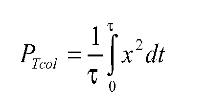
is used for the determination of the power of the disturbance force signal, in particular the power of the filtered disturbance force signal, wherein τ is a predetermined timeframe. By integration of the incremental samples of the disturbance force signal within the predetermined timeframe τ, a reduction of the information density can be achieved, since the result of the integration, the power PTcol of the disturbance force signal, is one value representing all samples of the disturbance force signal occurring in the timeframe τ. The timeframe τ is chosen with respect to the sample rate of the disturbance force signal and with respect to the frequency range of the oscillation frequency of the disturbance force signal. A typical value for τ is 1 second. - According to another preferred embodiment of the invention, the timeframe τ is determined by the period of an oscillation, in particular by the period of a square-wave oscillation, generated by means of a signal generator. The oscillation triggers the integration, in particular an increasing or decreasing slope of the oscillation serves as trigger for the integration. The oscillation provided by a signal generator allows an accurate determination of the timeframe τ, hence the result of the integration also fulfils high accuracy needs.
- According to another preferred embodiment of the invention, the computed power of the disturbance force signal is provided to a zero-order-hold algorithm, in particular serving as a digital-analogue-converter. The zero-order-hold algorithm converts the discrete-time signal into a continuous-time signal by holding each sample of the disturbance force signal for one sample interval.
- According to another preferred embodiment of the invention, an input signal for an unbalance-amount look-up table or unbalance-amount algorithm is computed by multiplication of the output of the digital filter for the vehicle velocity, the output of the digital filter for the steering wheel angle and the averaged disturbance force signal according to one of the claims 5 to 7 or the power of the disturbance force signal according to one of the claims 8 or 9. By multiplying the averaged force signal or the power of the disturbance force signal with the logical outputs of the filter means for the vehicle velocity signal and the steering wheel angle signal it is assured, that a computation or determination of an unbalance amount is solely executed, if the velocity is above the preset threshold and the steering wheel angle is below the preset threshold and hence the result of the computation is relevant for the nibble phenomenon. In any other case, the unbalance-amount lookup table or unbalance amount algorithm provides no unbalance amount, since the disturbance is not assumed to be the result of a nibble phenomenon.
- According to another preferred embodiment of the invention, an input signal for an unbalance-amount look-up table or unbalance-amount algorithm is computed by multiplication of the output of the digital filter for the vehicle velocity, the output of the digital filter for the steering wheel angle and the power of the disturbance force signal and dividing the result with τ .
- According to another aspect of the invention, an electronic control unit for an electric power steering system is provided, which electronic control unit is programmed to execute the method according to one of the
claims 1 to 12. - According to another aspect of the invention, an electric power steering system comprising an electronic control unit according to claim 13. is provided.
- Other features and advantages of the present invention will be readily appreciated and better understood after reading the subsequent description when considered in connection with the accompanying drawings.
- Fig. 1
- is a schematic drawing of an electric assisted power steering apparatus according to the invention,
- Fig. 2
- is a flow chart illustrating the basic function blocks of the method accord- ing to a first embodiment of the invention,
- Fig. 3
- is a flow chart illustrating the basic function blocks of the method accord- ing to a second embodiment of the invention,
- Fig. 4
- is a flow chart illustrating the basic function blocks of the method accord- ing to a third embodiment of the invention.
- The electric power assisted steering system according to
Fig. 1 includes asteering wheel 10 to be operated by a driver, a steeringshaft 12 joining thesteering wheel 10 with asteering rack 14. Thesteering rack 14 meshes with apinion 16, which pinion 16 is connected to the steeringshaft 12. Atorque sensor 18 is attached to the steeringshaft 12 to detect torsion of the steeringshaft 12 corresponding proportionally to the steering torque at thesteering wheel 10. Thetorque sensor 18 is electrically connected toECU 20, whichECU 20 analyzes the signals of thetorque sensor 18 an computes an assist torque. The assist torque is translated into an electric current, which current is provided to anelectric motor 22. Theelectric motor 22 is coupled to the steeringshaft 12 and is capable of providing an assist torque to the steeringshaft 12. The torque in the steeringshaft 12 generates by meshing of thepinion 16 axial forces in the direction of the longest extension of thesteering rack 14. Thesteering rack 14 is coupled to steeringknuckles 24, which steeringknuckles 24 are rotatably mounted at a car body (not shown). The steeringknuckles 24 serve as axles for thewheels 26, whichwheels 26 can be rotated by a linear movement of thesteering rack 14 to allow the steering of the vehicle. - Additional sensors like a
velocity sensor 28, a steeringwheel angle sensor 30 and abrake sensor 32 provide their signals to theECU 20. Hence, theECU 20 is enabled to compute the assist torque and the amount of electric power to be provided to theelectric motor 22 dependent on the signal of thetorque sensor 18 and at least one signal of theadditional sensors - The torque at the
torque sensor 18 is related to internal and external forces and torques applied to the steering system. If the driver turns the steering wheel, thewheels 26 provide a reaction force, which reaction force results in a feedback force to the driver. Some reaction forces are needed to ensure a proper feeling for the driver. Other reaction forces, e.g. reaction forces related to unbalanced tires or uneven brake disc surfaces, do not give any useful information to the driver and therefore shall be eliminated or at least partially compensated to improve the drivers comfort. - The algorithms according to preferred embodiments of the invention are illustrated in
Figs. 2 to 4 . -
Fig. 2 shows a first embodiment of an algorithm according to the invention. The steering torque or column torque detected by thetorque sensor 18 according toFig. 1 is an input for the algorithm according toFig. 2 . The steering torque signal is filtered by means of ahighpass filter 34 to mask out frequencies below a predetermined threshold, for example below 8 Hz, which are not relevant for the determination of the nibble phenomenon. The filtered steering torque signal is provided to absolute value generating means 36, having an algorithm that generates an absolute value out of each sample of the filtered torque signal. The absolute values of the filtered torque signal are provided to a moving average filter 38, which moving average filter 38 generates an average value of a group of m values, wherein m is the size of the moving average filter. With each new maximum value being provided to the averaging module 38, the oldest value in the averaging module 38 is not taken any longer into account. The output of the averaging module 38 is an averaged torque value based on a number of m samples. - Other inputs for the algorithm according to
Fig. 2 are the vehicle speed signal determined by thevehicle speed sensor 28 and the steering wheel angle determined by the steeringwheel angle sensor 30. The signals of thesensors digital filters digital filter 40 for the velocity signal outputs a logical "high" or "1 ", if the velocity is above a preset threshold, hence vibrations occurring in a velocity range below the threshold are assumed to be irrelevant for the nibble determination. Thedigital filter 42 for the steering wheel angle signal outputs a logical "high" or "1", if the steering wheel angle is below a preset threshold, hence vibrations occurring in a steering wheel angle range above the threshold are assumed to be irrelevant for the nibble determination. - As a result, a multiplication of the averaged torque value with the output signals of the
digital filters digital filters unbalance classifier 44 and an unbalance amount is determined and output for further processing in theECU 20. In parallel, the result of the multiplication procedure, the disturbance torque, can be utilized for other purposes, e.g. for being displayed to the driver. - According to
Fig. 3 , the algorithm according to the second embodiment of the invention is provided with the same input signals as the algorithm according toFig. 2 . The filtered steering torque signal is provided to integration means 46 and 48, controlled by a signal-generator 50 providing a square-wave oscillation. By integration according to the equation:
the power of the disturbance force signal is determined. The integration interval includes the values of the filtered torque signal within the timeframe from 0 to τ , wherein τ is determined by half of the period of the oscillation frequency provided by thesignal generator 50. - The algorithm according to
Fig. 4 is a modification of the algorithm according toFig. 3 , wherein the frequency provided by the signal generator is higher than 0,5 Hz and hence the timeframe for τ is smaller than 1 second. To avoid an unstable signal input for theunbalance classifier 44, the integration result is provided to zero-order-means 52, which zero-order-means 52 stabilize the signal output by holding each sample value for one sample interval. For the compensation of the effects of the zero-order-means 52, the output signal is divided by the sample period τ , illustrated inFig. 4 as input signal T for the determination of the disturbance power. - A multiplication of the disturbance power value with the output signals of the
digital filters digital filters unbalance classifier 44 and an unbalance amount is determined and output for further processing in theECU 20. In parallel, the result of the multiplication procedure, the disturbance power, can be utilized for other purposes, e.g. for being displayed to the driver or for workshop diagnosis to identify the amount of unbalance in the front wheels.
Claims (14)
- A method for operating an electric power steering system having an electronic control unit (20) for controlling of an electric power applied to an electric motor (22), which electric motor (22) generates assist torque for assisting steering of a steering wheel (10), said assist torque being computed by means of an algorithm, which algorithm comprises the steps of:- determination of a disturbance force signal related to internal and/or external forces acting on the electric power steering system,- determination of a vehicle velocity,- determination of a steering wheel angle,- modification of the disturbance force signal by means of at least one computation procedure,- computation of a disturbance value, in particular a disturbance torque or a disturbance power, with the input signals: modified disturbance force signal, steering wheel angle signal, vehicle velocity signal,- provision of the vehicle velocity signal and the disturbance value to classification means for the determination of an unbalance amount,- at least partial compensation of the external forces by application of electric power to the electric motor (22) in accordance with the calculated disturbance value and the unbalance amount and/or indication of the unbalance amount to the driver.
- The method according to claim 1,
characterized in that
the disturbance force signal is filtered by filter means, in particular a highpass-filter (34), having a lower cut-off frequency of at least 5 Hz, preferably of at least 8 Hz, in particular at least 10 Hz. - The method according to claim 1 or 2,
characterized in that
the vehicle velocity signal is filtered by digital filter means (40), preferably a digital bandpass filter, in particular a digital highpass-filter, having a lower cut-off limitation corresponding to 60 kilometres per hour and providing a logical output signal. - The method according to one of the preceding claims,
characterized in that
the steering wheel angle is filtered by digital filter means (42), preferably a digital lowpass-filter, having an upper cut-off limitation corresponding to 10 - 20 degrees and providing a logical output signal. - The method according to one of the preceding claims,
characterized in that
the filtered disturbance force signal is provided to averaging means (38) to compute an averaged disturbance force signal, which averaging means using the equation:
where m is the size of the moving average filter; n is the signal index; k is the counter; x is the input signal and y is the output signal. - The method according to claim 5,
characterized in that
the filtered disturbance force signal is provided to the averaging means after passing absolute value generating means (36). - The method according to one of claims 1 to 4,
characterized in that
the power of the disturbance force signal, in particular the power of the filtered disturbance force signal, is determined. - The method according to claim 7,
characterized in that
the equation:
is used for the determination of the power of the disturbance force signal, in particular the power of the filtered disturbance force signal, wherein τ is a predetermined timeframe. - The method according to claim 8,
characterized in that
τ is determined by the period of an oscillation, in particular by the period of a square-wave oscillation, generated by means of a signal generator (50). - The method according to claim 8 or 9,
characterized in that
the computed power of the disturbance force signal is provided to a zero-order-hold algorithm (52), in particular serving as a digital-analogue-converter. - The method according to one of the preceding claims,
characterized in that
an input signal for an unbalance-amount look-up table (44) or unbalance-amount algorithm is computed by multiplication of the output of the digital filter (40) for the vehicle velocity, the output of the digital filter (42) for the steering wheel angle and the averaged disturbance force signal according to one of the claims 5 to 7 or the power of the disturbance force signal according to one of the claims 8 or 9. - The method according to claim 10,
characterized in that
an input signal for an unbalance-amount look-up table (44) or unbalance-amount algorithm is computed by multiplication of the output of the digital filter (40) for the vehicle velocity, the output of the digital filter (42) for the steering wheel angle and the power of the disturbance force signal according to claim 10 and dividing the result with τ . - An electronic control (20) unit for an electric power steering system, which electronic control unit is programmed to execute the method according to one of the claims 1 to 12.
- An electric power steering system comprising an electronic control unit according (20) to claim 13.
Priority Applications (1)
| Application Number | Priority Date | Filing Date | Title |
|---|---|---|---|
| EP07115063.5A EP2030868B1 (en) | 2007-08-28 | 2007-08-28 | Method for operating an electric power steering system, electronic control unit for an electric power steering system and electric power steering system |
Applications Claiming Priority (1)
| Application Number | Priority Date | Filing Date | Title |
|---|---|---|---|
| EP07115063.5A EP2030868B1 (en) | 2007-08-28 | 2007-08-28 | Method for operating an electric power steering system, electronic control unit for an electric power steering system and electric power steering system |
Publications (2)
| Publication Number | Publication Date |
|---|---|
| EP2030868A1 true EP2030868A1 (en) | 2009-03-04 |
| EP2030868B1 EP2030868B1 (en) | 2016-08-10 |
Family
ID=38983286
Family Applications (1)
| Application Number | Title | Priority Date | Filing Date |
|---|---|---|---|
| EP07115063.5A Not-in-force EP2030868B1 (en) | 2007-08-28 | 2007-08-28 | Method for operating an electric power steering system, electronic control unit for an electric power steering system and electric power steering system |
Country Status (1)
| Country | Link |
|---|---|
| EP (1) | EP2030868B1 (en) |
Cited By (8)
| Publication number | Priority date | Publication date | Assignee | Title |
|---|---|---|---|---|
| US20100211263A1 (en) * | 2009-02-13 | 2010-08-19 | Gm Global Technology Operations, Inc. | Learning controller for the compensation of torque pulsations in a steering assembly |
| EP2834132A4 (en) * | 2012-04-05 | 2015-12-30 | Trw Automotive Us Llc | System and method for wheel disturbance order detection and correction |
| US9266558B2 (en) | 2010-09-15 | 2016-02-23 | GM Global Technology Operations LLC | Methods, systems and apparatus for steering wheel vibration reduction in electric power steering systems |
| US9327762B2 (en) | 2010-12-14 | 2016-05-03 | GM Global Technology Operations LLC | Electric power steering systems with improved road feel |
| US9440674B2 (en) | 2010-09-15 | 2016-09-13 | GM Global Technology Operations LLC | Methods, systems and apparatus for steering wheel vibration reduction in electric power steering systems |
| DE102016219047A1 (en) | 2015-11-16 | 2017-05-18 | Ford Global Technologies, Llc | Method for compensating a disturbance torque occurring on a steering wheel of a vehicle steering system |
| CN110562319A (en) * | 2019-10-09 | 2019-12-13 | 重庆鹤姿汽车科技有限公司 | control method of electric power steering gear |
| CN110626420A (en) * | 2018-06-25 | 2019-12-31 | 操纵技术Ip控股公司 | Driver Notification Using Handheld Steering Wheel Actuators in Steer-by-Wire Systems |
Citations (9)
| Publication number | Priority date | Publication date | Assignee | Title |
|---|---|---|---|---|
| DE4133238A1 (en) * | 1991-10-05 | 1993-04-08 | Bosch Gmbh Robert | Signal derivation system for real=time evaluation of road surface profile under motor vehicle - has monitors for vertical deflections of wheels and with data reduction signal processing to classify profiles |
| DE19906300A1 (en) | 1999-02-15 | 2000-08-17 | Bosch Gmbh Robert | Imbalance and air pressure detection through steering moments |
| US6134490A (en) | 1998-05-19 | 2000-10-17 | Denso Corporation | Power steering device assisted by variable power |
| DE10119967A1 (en) * | 2000-07-19 | 2002-02-14 | Mitsubishi Electric Corp | Control device for electrically-operated power-steering device, has learning unit which determines the difference between the resulting friction and the return torque |
| US6742620B2 (en) | 2001-07-28 | 2004-06-01 | Ford Global Technologies, Llc | Power steering system with vehicle braking state input for vibration reduction |
| EP1574417A1 (en) * | 2004-03-11 | 2005-09-14 | Peugeot Citroen Automobiles S.A. | Electric power steering apparatus for an automotive vehicle, steering assembly having such an apparatus and automotive vehicle equipped with such an assembly |
| EP1857349A1 (en) * | 2006-05-16 | 2007-11-21 | Ford Global Technologies, LLC | Method for improving the heading of a vehicle and associated steering system |
| EP2014537A2 (en) | 2007-07-13 | 2009-01-14 | Jtekt Corporation | Electric power steering apparatus and method for controling same |
| EP2028080A1 (en) | 2007-08-23 | 2009-02-25 | Ford Global Technologies, LLC | Method for operating an electric power steering system, electronic control unit for an electric power steering system and electric power steering system |
-
2007
- 2007-08-28 EP EP07115063.5A patent/EP2030868B1/en not_active Not-in-force
Patent Citations (9)
| Publication number | Priority date | Publication date | Assignee | Title |
|---|---|---|---|---|
| DE4133238A1 (en) * | 1991-10-05 | 1993-04-08 | Bosch Gmbh Robert | Signal derivation system for real=time evaluation of road surface profile under motor vehicle - has monitors for vertical deflections of wheels and with data reduction signal processing to classify profiles |
| US6134490A (en) | 1998-05-19 | 2000-10-17 | Denso Corporation | Power steering device assisted by variable power |
| DE19906300A1 (en) | 1999-02-15 | 2000-08-17 | Bosch Gmbh Robert | Imbalance and air pressure detection through steering moments |
| DE10119967A1 (en) * | 2000-07-19 | 2002-02-14 | Mitsubishi Electric Corp | Control device for electrically-operated power-steering device, has learning unit which determines the difference between the resulting friction and the return torque |
| US6742620B2 (en) | 2001-07-28 | 2004-06-01 | Ford Global Technologies, Llc | Power steering system with vehicle braking state input for vibration reduction |
| EP1574417A1 (en) * | 2004-03-11 | 2005-09-14 | Peugeot Citroen Automobiles S.A. | Electric power steering apparatus for an automotive vehicle, steering assembly having such an apparatus and automotive vehicle equipped with such an assembly |
| EP1857349A1 (en) * | 2006-05-16 | 2007-11-21 | Ford Global Technologies, LLC | Method for improving the heading of a vehicle and associated steering system |
| EP2014537A2 (en) | 2007-07-13 | 2009-01-14 | Jtekt Corporation | Electric power steering apparatus and method for controling same |
| EP2028080A1 (en) | 2007-08-23 | 2009-02-25 | Ford Global Technologies, LLC | Method for operating an electric power steering system, electronic control unit for an electric power steering system and electric power steering system |
Cited By (10)
| Publication number | Priority date | Publication date | Assignee | Title |
|---|---|---|---|---|
| US20100211263A1 (en) * | 2009-02-13 | 2010-08-19 | Gm Global Technology Operations, Inc. | Learning controller for the compensation of torque pulsations in a steering assembly |
| US8589030B2 (en) * | 2009-02-13 | 2013-11-19 | GM Global Technology Operations LLC | Learning controller for the compensation of torque pulsations in a steering assembly |
| US9266558B2 (en) | 2010-09-15 | 2016-02-23 | GM Global Technology Operations LLC | Methods, systems and apparatus for steering wheel vibration reduction in electric power steering systems |
| US9440674B2 (en) | 2010-09-15 | 2016-09-13 | GM Global Technology Operations LLC | Methods, systems and apparatus for steering wheel vibration reduction in electric power steering systems |
| US9327762B2 (en) | 2010-12-14 | 2016-05-03 | GM Global Technology Operations LLC | Electric power steering systems with improved road feel |
| EP2834132A4 (en) * | 2012-04-05 | 2015-12-30 | Trw Automotive Us Llc | System and method for wheel disturbance order detection and correction |
| DE102016219047A1 (en) | 2015-11-16 | 2017-05-18 | Ford Global Technologies, Llc | Method for compensating a disturbance torque occurring on a steering wheel of a vehicle steering system |
| DE102016219047B4 (en) * | 2015-11-16 | 2019-10-31 | Ford Global Technologies, Llc | Method for compensating a disturbance torque occurring on a steering wheel of a vehicle steering system |
| CN110626420A (en) * | 2018-06-25 | 2019-12-31 | 操纵技术Ip控股公司 | Driver Notification Using Handheld Steering Wheel Actuators in Steer-by-Wire Systems |
| CN110562319A (en) * | 2019-10-09 | 2019-12-13 | 重庆鹤姿汽车科技有限公司 | control method of electric power steering gear |
Also Published As
| Publication number | Publication date |
|---|---|
| EP2030868B1 (en) | 2016-08-10 |
Similar Documents
| Publication | Publication Date | Title |
|---|---|---|
| EP2028080B1 (en) | Method for operating an electric power steering system, electronic control unit for an electric power steering system and electric power steering system | |
| EP2030868B1 (en) | Method for operating an electric power steering system, electronic control unit for an electric power steering system and electric power steering system | |
| EP0282041B1 (en) | A yaw motion control device for a vehicle | |
| EP1275937B1 (en) | Physical amount estimating apparatus; road surface friction condition estimating apparatus, steering angle neutral point estimating apparatus and air pressure reduction estimating apparatus | |
| JP4015848B2 (en) | Misalignment detection apparatus and method for vehicle steering system using torque of steering wheel | |
| EP2248709B1 (en) | Vehicle steering apparatus | |
| US20020042671A1 (en) | Motor vehicle with supplemental rear steering having open and closed loop modes | |
| EP2605949B1 (en) | Vehicle active steering shimmy mitigation | |
| EP2189357B1 (en) | Electric power steering apparatus for vehicles | |
| JP6722355B2 (en) | Apparatus and method for detecting manual steering wheel operation | |
| JP2004074842A (en) | Road surface friction state estimation device | |
| EP2079625B1 (en) | Electric power assisted steering assembly | |
| CN114379288A (en) | Method for early detection of irregular wear of motor vehicle tyres and/or unintentional changes in chassis settings | |
| US8447470B2 (en) | Method for determining, in real time, the grip on a steering wheel of an electric power-assisted steering system for automobile | |
| JP2021142955A (en) | Vehicle control device and vehicle | |
| DE102015006466A1 (en) | vehicle | |
| US6619422B2 (en) | Steering unit and internal drag calculation apparatus used therein | |
| DE102011008337A1 (en) | Method for detecting defect e.g. tear, in electromechanical steering system of vehicle, involves generating fault memory entry when time duration in predetermined guidance maneuver is greater than predetermined measure of reference duration | |
| JP4363118B2 (en) | Road surface state determination method and road surface state determination device | |
| US20020022915A1 (en) | Motor vehicle with supplemental rear steering having open and closed loop modes | |
| JP3927531B2 (en) | Control device for vehicle steering system | |
| CN210634626U (en) | Car rollover prevention system | |
| JP2022092855A (en) | Road surface state detection device, and power steering device having the road surface state detection device | |
| US20120022745A1 (en) | Method for operating a steering system | |
| US12522279B2 (en) | Mitigation of traction steer disturbance from driver feedback torque in steer-by-wire vehicles |
Legal Events
| Date | Code | Title | Description |
|---|---|---|---|
| PUAI | Public reference made under article 153(3) epc to a published international application that has entered the european phase |
Free format text: ORIGINAL CODE: 0009012 |
|
| AK | Designated contracting states |
Kind code of ref document: A1 Designated state(s): AT BE BG CH CY CZ DE DK EE ES FI FR GB GR HU IE IS IT LI LT LU LV MC MT NL PL PT RO SE SI SK TR |
|
| AX | Request for extension of the european patent |
Extension state: AL BA HR MK RS |
|
| 17P | Request for examination filed |
Effective date: 20090904 |
|
| AKX | Designation fees paid |
Designated state(s): DE FR GB |
|
| 17Q | First examination report despatched |
Effective date: 20120126 |
|
| GRAP | Despatch of communication of intention to grant a patent |
Free format text: ORIGINAL CODE: EPIDOSNIGR1 |
|
| INTG | Intention to grant announced |
Effective date: 20160506 |
|
| INTG | Intention to grant announced |
Effective date: 20160513 |
|
| GRAS | Grant fee paid |
Free format text: ORIGINAL CODE: EPIDOSNIGR3 |
|
| GRAA | (expected) grant |
Free format text: ORIGINAL CODE: 0009210 |
|
| AK | Designated contracting states |
Kind code of ref document: B1 Designated state(s): DE FR GB |
|
| REG | Reference to a national code |
Ref country code: GB Ref legal event code: FG4D |
|
| REG | Reference to a national code |
Ref country code: DE Ref legal event code: R096 Ref document number: 602007047338 Country of ref document: DE |
|
| REG | Reference to a national code |
Ref country code: FR Ref legal event code: PLFP Year of fee payment: 10 |
|
| PGFP | Annual fee paid to national office [announced via postgrant information from national office to epo] |
Ref country code: GB Payment date: 20160926 Year of fee payment: 10 |
|
| PGFP | Annual fee paid to national office [announced via postgrant information from national office to epo] |
Ref country code: FR Payment date: 20160929 Year of fee payment: 10 |
|
| PGFP | Annual fee paid to national office [announced via postgrant information from national office to epo] |
Ref country code: DE Payment date: 20160930 Year of fee payment: 10 |
|
| REG | Reference to a national code |
Ref country code: DE Ref legal event code: R097 Ref document number: 602007047338 Country of ref document: DE |
|
| PLBE | No opposition filed within time limit |
Free format text: ORIGINAL CODE: 0009261 |
|
| STAA | Information on the status of an ep patent application or granted ep patent |
Free format text: STATUS: NO OPPOSITION FILED WITHIN TIME LIMIT |
|
| 26N | No opposition filed |
Effective date: 20170511 |
|
| REG | Reference to a national code |
Ref country code: DE Ref legal event code: R119 Ref document number: 602007047338 Country of ref document: DE |
|
| GBPC | Gb: european patent ceased through non-payment of renewal fee |
Effective date: 20170828 |
|
| REG | Reference to a national code |
Ref country code: FR Ref legal event code: ST Effective date: 20180430 |
|
| PG25 | Lapsed in a contracting state [announced via postgrant information from national office to epo] |
Ref country code: DE Free format text: LAPSE BECAUSE OF NON-PAYMENT OF DUE FEES Effective date: 20180301 Ref country code: GB Free format text: LAPSE BECAUSE OF NON-PAYMENT OF DUE FEES Effective date: 20170828 |
|
| PG25 | Lapsed in a contracting state [announced via postgrant information from national office to epo] |
Ref country code: FR Free format text: LAPSE BECAUSE OF NON-PAYMENT OF DUE FEES Effective date: 20170831 |