EP2030543A2 - Stick type vacuum cleaner - Google Patents
Stick type vacuum cleaner Download PDFInfo
- Publication number
- EP2030543A2 EP2030543A2 EP08006179A EP08006179A EP2030543A2 EP 2030543 A2 EP2030543 A2 EP 2030543A2 EP 08006179 A EP08006179 A EP 08006179A EP 08006179 A EP08006179 A EP 08006179A EP 2030543 A2 EP2030543 A2 EP 2030543A2
- Authority
- EP
- European Patent Office
- Prior art keywords
- dust
- separating unit
- suction port
- vacuum cleaner
- type vacuum
- Prior art date
- Legal status (The legal status is an assumption and is not a legal conclusion. Google has not performed a legal analysis and makes no representation as to the accuracy of the status listed.)
- Granted
Links
Images


Classifications
-
- A—HUMAN NECESSITIES
- A47—FURNITURE; DOMESTIC ARTICLES OR APPLIANCES; COFFEE MILLS; SPICE MILLS; SUCTION CLEANERS IN GENERAL
- A47L—DOMESTIC WASHING OR CLEANING; SUCTION CLEANERS IN GENERAL
- A47L5/00—Structural features of suction cleaners
- A47L5/12—Structural features of suction cleaners with power-driven air-pumps or air-compressors, e.g. driven by motor vehicle engine vacuum
- A47L5/22—Structural features of suction cleaners with power-driven air-pumps or air-compressors, e.g. driven by motor vehicle engine vacuum with rotary fans
- A47L5/28—Suction cleaners with handles and nozzles fixed on the casings, e.g. wheeled suction cleaners with steering handle
-
- A—HUMAN NECESSITIES
- A47—FURNITURE; DOMESTIC ARTICLES OR APPLIANCES; COFFEE MILLS; SPICE MILLS; SUCTION CLEANERS IN GENERAL
- A47L—DOMESTIC WASHING OR CLEANING; SUCTION CLEANERS IN GENERAL
- A47L5/00—Structural features of suction cleaners
- A47L5/12—Structural features of suction cleaners with power-driven air-pumps or air-compressors, e.g. driven by motor vehicle engine vacuum
- A47L5/22—Structural features of suction cleaners with power-driven air-pumps or air-compressors, e.g. driven by motor vehicle engine vacuum with rotary fans
- A47L5/24—Hand-supported suction cleaners
-
- A—HUMAN NECESSITIES
- A47—FURNITURE; DOMESTIC ARTICLES OR APPLIANCES; COFFEE MILLS; SPICE MILLS; SUCTION CLEANERS IN GENERAL
- A47L—DOMESTIC WASHING OR CLEANING; SUCTION CLEANERS IN GENERAL
- A47L5/00—Structural features of suction cleaners
- A47L5/12—Structural features of suction cleaners with power-driven air-pumps or air-compressors, e.g. driven by motor vehicle engine vacuum
- A47L5/22—Structural features of suction cleaners with power-driven air-pumps or air-compressors, e.g. driven by motor vehicle engine vacuum with rotary fans
- A47L5/28—Suction cleaners with handles and nozzles fixed on the casings, e.g. wheeled suction cleaners with steering handle
- A47L5/30—Suction cleaners with handles and nozzles fixed on the casings, e.g. wheeled suction cleaners with steering handle with driven dust-loosening tools, e.g. rotating brushes
-
- A—HUMAN NECESSITIES
- A47—FURNITURE; DOMESTIC ARTICLES OR APPLIANCES; COFFEE MILLS; SPICE MILLS; SUCTION CLEANERS IN GENERAL
- A47L—DOMESTIC WASHING OR CLEANING; SUCTION CLEANERS IN GENERAL
- A47L9/00—Details or accessories of suction cleaners, e.g. mechanical means for controlling the suction or for effecting pulsating action; Storing devices specially adapted to suction cleaners or parts thereof; Carrying-vehicles specially adapted for suction cleaners
- A47L9/10—Filters; Dust separators; Dust removal; Automatic exchange of filters
- A47L9/16—Arrangement or disposition of cyclones or other devices with centrifugal action
- A47L9/1608—Cyclonic chamber constructions
-
- A—HUMAN NECESSITIES
- A47—FURNITURE; DOMESTIC ARTICLES OR APPLIANCES; COFFEE MILLS; SPICE MILLS; SUCTION CLEANERS IN GENERAL
- A47L—DOMESTIC WASHING OR CLEANING; SUCTION CLEANERS IN GENERAL
- A47L9/00—Details or accessories of suction cleaners, e.g. mechanical means for controlling the suction or for effecting pulsating action; Storing devices specially adapted to suction cleaners or parts thereof; Carrying-vehicles specially adapted for suction cleaners
- A47L9/10—Filters; Dust separators; Dust removal; Automatic exchange of filters
- A47L9/16—Arrangement or disposition of cyclones or other devices with centrifugal action
- A47L9/1658—Construction of outlets
- A47L9/1666—Construction of outlets with filtering means
-
- A—HUMAN NECESSITIES
- A47—FURNITURE; DOMESTIC ARTICLES OR APPLIANCES; COFFEE MILLS; SPICE MILLS; SUCTION CLEANERS IN GENERAL
- A47L—DOMESTIC WASHING OR CLEANING; SUCTION CLEANERS IN GENERAL
- A47L9/00—Details or accessories of suction cleaners, e.g. mechanical means for controlling the suction or for effecting pulsating action; Storing devices specially adapted to suction cleaners or parts thereof; Carrying-vehicles specially adapted for suction cleaners
- A47L9/10—Filters; Dust separators; Dust removal; Automatic exchange of filters
- A47L9/16—Arrangement or disposition of cyclones or other devices with centrifugal action
- A47L9/1683—Dust collecting chambers; Dust collecting receptacles
-
- A—HUMAN NECESSITIES
- A47—FURNITURE; DOMESTIC ARTICLES OR APPLIANCES; COFFEE MILLS; SPICE MILLS; SUCTION CLEANERS IN GENERAL
- A47L—DOMESTIC WASHING OR CLEANING; SUCTION CLEANERS IN GENERAL
- A47L9/00—Details or accessories of suction cleaners, e.g. mechanical means for controlling the suction or for effecting pulsating action; Storing devices specially adapted to suction cleaners or parts thereof; Carrying-vehicles specially adapted for suction cleaners
- A47L9/10—Filters; Dust separators; Dust removal; Automatic exchange of filters
- A47L9/16—Arrangement or disposition of cyclones or other devices with centrifugal action
- A47L9/1691—Mounting or coupling means for cyclonic chamber or dust receptacles
Definitions
- the present disclosure relates to a stick type vacuum cleaner, and more particularly, to a stick type vacuum cleaner, which has a power supply unit such as a battery of increased life span, and is capable of reducing noise level.
- Vacuum cleaners are among the most widely used home electronic appliances. Vacuum cleaners draw in air and dust from a surface being cleaned, using a suction force generated by a vacuum source.
- a canister vacuum cleaner includes a main body, a suction port assembly, and a connecting part.
- the main body includes a suction force generating unit and a dust separating unit to separate dust from air and collect the separated dust.
- the suction force generating unit includes an impeller which is generally rotatably installed, and a suction motor to rotate the impeller.
- the suction port assembly moves along an object being cleaned, drawing in dust and air through a suction port.
- the connecting part connects the suction port assembly with the main body, and includes a handgrip, an extension pipe to connect the suction port assembly and the handgrip, and a flexible hose to connect the handgrip and the main body.
- the canister type vacuum cleaner includes a power line which is exposed to outside to supply power to the suction force generating unit.
- a plug formed on one end of the power line is inserted in a socket formed in walls of a room to supply power to the suction force generating unit.
- a user of a canister type vacuum cleaner moves not only the suction port assembly, but also the main body engaged with the suction port assembly. While using the vacuum cleaner, the user has to be careful not to hit the objects nearby.
- a stick type vacuum cleaner is one of those cleaners that are proposed to overcome such inconveniences mentioned above.
- a stick type vacuum cleaner is similar to a canister type cleaner in that it includes a suction port assembly, an extension pipe and a handgrip.
- a stick type vacuum cleaner skips the main body, and instead accommodates a suction force generating unit and a dust separating unit in the suction port assembly.
- the suction port assembly of the stick type vacuum cleaner draws in dust using a suction force generated therefrom, and also collects the separated dust therein.
- the stick type vacuum cleaner usually accommodates a power supply unit such as a battery in the suction force generating unit to supply power to the suction force generating unit, and so does not require a separate power line.
- a suction force generating unit is arranged at a rear portion of the dust separating unit. Accordingly, a vacuum pressure of the suction force generating unit is transmitted to the suction port via the dust separating unit.
- the dust separating unit can be damaged by the vacuum pressure being transmitted to the suction port. Therefore, the suction force generating unit has to rotate the impeller at relatively fast speed to overcome loss of pressure in the dust separating unit and to provide the suction port with sufficient suction force.
- the suction force generating unit When the suction force generating unit is arranged at a rear side of the cleaner like in the stick type vacuum cleaner, the suction force generating unit consumes a relatively large amount of power, causing decrease of life span of the power supply unit such as battery which supplies power to the suction force generating unit. Furthermore, the impeller generates offensive noise during its fast rotation.
- Exemplary embodiments of the present disclosure overcome the above disadvantages and other disadvantages not described above. Accordingly, it is an object of the present disclosure to provide a stick type vacuum cleaner which has a power supply unit of increased life span, and is capable of reducing noise level of the suction force generating unit.
- An aspect of the present disclosure provides a stick type vacuum cleaner which includes a suction port assembly movable along an object being cleaned to draw in dust and air from the object, and a stick unit in which a first end is engaged with a first side of the suction port assembly and a second end comprises a handgrip so that a user can grip the handgrip to move the suction port assembly along the object being cleaned.
- the suction port assembly may include a casing part comprising a suction port through which air and dust are drawn from the object being cleaned, a suction force generating unit formed inside the casing part to generate a suction force, a dust separating unit to separate dust from the drawn air and dust and accommodate the separated dust therein, and a power supply unit to supply power to the suction force generating unit.
- the suction force generating unit may be disposed between the suction port and the dust separating unit so that the drawn air and dust pass through the suction force generating unit before being introduced into the dust separating unit.
- the suction force generating unit may include an impeller disposed to be exposed to a passage defined between the suction port and the dust separating unit, to generate the suction force by rotational movement, and a suction motor to receive a power from the power supply unit and rotate the impeller.
- the dust separating unit may include a cyclone chamber to separate dust from the air and dust drawn through the suction port by using a centrifugal force, and a dust collecting chamber to accommodate the dust separated from the cyclone chamber.
- the dust separating unit may include a cyclone dust separating unit in which the cyclone chamber and the dust collecting chamber are arranged in parallel, in a manner such that a cyclone inlet is formed on a first side and the cyclone chamber and the dust collecting chamber are open in a second side, and a side cover to cover the second side of the cyclone dust separating unit, and comprising an air discharge pipe to guide the air to be discharged from the cyclone chamber.
- the dust separating unit may include a filter member formed on an outer surface of the side cover to filter remaining dust from the air being discharged from the cyclone chamber, and a filter support member removably formed on the outer surface of the side cover to support the filter member formed on the side cover.
- the filter support member may include at least one air passing hole.
- An upper side of the cyclone dust separating unit may be made out of a transparent material to enable a user to see the cyclone chamber and the dust collecting chamber therethrough.
- the casing part may include a dust separating unit chamber so that the dust separating unit is removably housed in the dust separating unit chamber.
- the suction port assembly may further include a rotatable brush movably formed in the suction port, and a rotatable brush motor to drive the rotatable brush.
- the rotatable brush motor may receive power from the power generating unit.
- the stick part may include an engaging part engaged to a first side of the suction port assembly, a stick type extension part extended from the engaging part, and a handgrip formed on one end of the stick-type extension part.
- the power generating unit may include a battery removably disposed inside the casing part.
- a stick type vacuum cleaner 1 according to an exemplary embodiment of the present disclosure includes a suction port assembly 100, and a stick part 200.
- the suction port assembly 100 is disposed to be moved along an object being cleaned, and to draw in dust from the object and collect the drawn dust therein.
- the stick part 200 is engaged with a rear portion of the suction port assembly 100 to facilitate a user's operation of the suction port assembly 100 along the object being cleaned.
- the stick part 200 includes an engaging part 210 formed on a rear portion of the suction port assembly 100, a stick-type extension part 220 extending from the engaging part 210, and a handgrip 230 formed on an upper portion of the stick-type extension part 220.
- the suction port assembly 100 includes a casing part 110, a rotatable brush 120, a rotatable brush motor 121, a power supply 130, a suction force generating unit 140, and a dust separating unit 150.
- the casing part 110 includes an upper casing 111 and a lower casing 112.
- the upper casing 111 includes a dust separating unit chamber S to receive the dust separating unit 150 therein.
- the upper casing 111 also includes a plurality of air discharge holes 111a formed in a rear portion to permit the clean air to be discharged outside the suction port assembly 100 after the dust is separated in the dust separating unit 150.
- the lower casing 112 includes a suction port 112a formed on the front portion. Dust and air can be drawn into the suction port assembly 100 through the suction port 112a.
- the rotatable brush 120 is formed on the front portion of the lower casing 112, to be disposed in the suction port 112a.
- the rotatable brush 120 is rotated by the rotatable brush motor 121, to hit with its lower portion the object being cleaned and remove dust from the object being cleaned.
- the rotatable brush motor 121 receives power supply from the power supply 130 ( FIG. 6 ).
- the power supply 130 according to the exemplary embodiment of the present disclosure is implemented as a replaceable battery 130 mounted inside the casing part 110.
- the battery 130 supplies power not only to the rotatable brush motor 121, but also to a suction motor 141 which will be explained below.
- the suction force generating unit 140 includes the suction motor 141, an impeller 142, and a suction port connecting pipe 143.
- the suction motor 141 receives power from the battery 130 to rotate the impeller 142.
- the impeller 142 is rotated by the suction motor 141 to generate a vacuum pressure, or suction force.
- the suction port connecting pipe 143 connects the suction port 112a and the impeller 142 to guide the air and dust drawn from the object being cleaned into the impeller 142.
- the suction port assembly 100 includes the suction force generating unit 140 and the battery 130 to supply power to the suction force generating unit 140 to generate a suction force.
- the vacuum cleaner 1 according to the exemplary embodiment of the present disclosure does not need a power line to receive external power.
- the suction force generating unit 140 is arranged in front of the dust separating unit 150. That is, the suction force generating unit 140 is provided between the suction port 112a and the dust separating unit 150. Air and dust are drawn through the suction port 112a, and then pass the suction force generating unit 140 and flow into the dust separating unit 150. More specifically, air and dust drawn through the suction port 112a flow into the dust separating unit 150 via the impeller 142 provided in the suction force generating unit 140.
- the impeller 142 is arranged on a fluid passage that connects the suction port 112a and the dust separating unit 150 according to the exemplary embodiment of the present disclosure. Therefore, the impeller 142 operates as a bypass impeller, while the motor to drive this bypass impeller operates as a bypass motor.
- the vacuum cleaner according to the exemplary embodiment of the present disclosure can provide almost unaffected level of suction force to the suction port 112a when the suction motor 141 rotates the impeller 142 with relatively slower speed.
- the suction force generating unit 140 is arranged in front of the dust separating unit 150, the vacuum pressure generated at the suction force generating unit 140 is transmitted to the suction port 112a intact, that is, without being affected by the dust separating unit 150. Furthermore, because the suction force generating unit 140 is arranged in front of the dust separating unit 150, the impeller 142 of the suction force generating unit 140 is able to draw in dust and air introduced through the suction port 112a using not only vacuum pressure, but also mechanical friction.
- the mechanical friction of the impeller 142 more specifically refers to a friction between air and dust with the rotating blades (not illustrated) of the impeller 142, which provides a moving force in the direction of the dust separating unit 150.
- the suction force generating unit 140 is arranged in back of the dust separating unit 150, the vacuum pressure generated by the suction force generating unit 140 can be transmitted to the suction port 112a via the dust separating unit 150. Accordingly, the dust separating unit 150 has the loss of vacuum pressure while the vacuum pressure is transmitted from the suction force generating unit 140 to the suction port 112a. Furthermore, if the suction force generating unit 140 is arranged in back of the dust separating unit 150, dust is filtered at the dust separating unit 150 already prior to arriving at the suction force generating unit 140, and therefore, it is impossible for the impeller 142 to draw the dust into the dust separating unit 150 by mechanical friction.
- the impeller 142 can be rotated at a relatively slower speed than when the suction force generating unit 140 is provided in back of the dust separating unit 150, but without compromising the level of suction force provided to the suction port 112a. Because the suction motor 141 consumes less power to rotate the impeller 142, the life span of the battery 130 to supply power to the suction motor 141 can be increased. Furthermore, because the rotational speed of the impeller 142 decreases, less amount of noise is generated from the rotation of the impeller 142.
- the dust separating unit 150 is removably mounted in the dust separating unit chamber (S) of the upper casing 111.
- the dust separating unit 150 includes a cyclone dust separating unit 160, a side cover 170, a filter member 180, and a filter support member 190.
- the cyclone dust separating unit 160 includes a cyclone inlet 162 formed in a first side 160a.
- the dust and air, after passing through the suction force generating unit 140, are introduced into the cyclone chamber 163 through the cyclone inlet 162.
- the cyclone dust separating unit 160 includes a cyclone chamber 163 and a dust collecting chamber 164 both formed therein.
- the cyclone chamber 163 separates, using a centrifugal force, dust from air that introduced through the cyclone inlet 162.
- the dust collecting chamber 164 collects the dust separated from the cyclone chamber 163.
- the cyclone chamber 163 and the dust collecting chamber 164 are arranged in parallel and divided from each other by a single partition 165.
- the cyclone chamber 163 and the dust collecting chamber 164 are open to a second side 160b of the cyclone dust separating unit 160.
- the cyclone dust separating unit 160 includes a dust separating unit handgrip 161 formed on an upper side 160c so that a user can grab it and carry the dust separating unit 150 with ease.
- the upper side 160c of the cyclone dust separating unit 160 may be made out of a transparent material to allow observance of the cyclone chamber 163 and the dust collecting chamber 164 from outside. Accordingly, a user is able to see and check the dust separating performance of the cyclone chamber 163 and also check the amount of dust collected in the dust collecting chamber 164, without having to disassemble the dust separating unit 150.
- the side cover 170 covers the second side 160b of the cyclone dust separating unit 160.
- the side cover 170 is detachably formed on the cyclone dust separating unit 160. If the dust collecting chamber 164 is full, the user detaches the side cover 170 from the cyclone dust separating unit 160 and empties the dust collecting chamber 170.
- the side cover 170 includes an air discharge pipe 171 formed thereon. Accordingly, clean air is discharged from the cyclone chamber 163 to the filter member 180 through the air discharge pipe 171 when dust is separated from the air.
- the filter member 180 is disposed on an outer side 172 of the side cover 170 to filter remaining dust from the air received from the cyclone chamber 163.
- the filter member 180 is supported by the filter support member 190 to remain engaged with the side cover 170.
- the filter support member 190 is detachably engaged with the side cover 170. Accordingly, if the filter member 180 gets too dusty, the filter support member 190 along with the filter member 180 is removed through the side cover 170 and a user can remove dust from the filter member 180.
- the filter support member 190 includes a plurality of air holes 191 for air to pass after passing through the filter member 180.
- the rotatable brush motor 121 receives power from the battery 130 to rotate the rotatable brush 120.
- the suction motor 141 also receives power from the battery 130 to rotate the impeller 142.
- the rotation of the impeller 142 generates a suction force (vacuum pressure), which is provided to the suction port 112a through the suction port connecting pipe 143 (see FIG. 2 ).
- the suction force generating unit 140 having the suction motor 141 and the impeller 142 is arranged between the dust separating unit 150 and the suction port 112a, unaffected level of suction force can be provided to the suction port 112a even when the suction motor 141 rotates the impeller 142 at a relatively lower speed.
- the battery 130 to supply power to the suction motor 141 can be used for a longer period of time.
- the impeller 142 rotates at a relatively slower speed, noise is reduced.
- the air and dust enter through the suction port 112a, and are introduced into the impeller 142 through the suction port connecting pipe 143 (see FIG. 2 ).
- the air and dust are then guided to the back of the cleaner by not only the suction force, but also the mechanical friction with the impeller 142, and guided to the cyclone inlet 162 of the cyclone dust separating unit 160. Because the air and dust are introduced into the cyclone inlet 162 by both the suction force and mechanical friction, output of the suction motor 141 to rotate the impeller 142 can be relatively reduced.
- air and dust enter the cyclone inlet 162 and rotate inside the cyclone chamber 163 towards the side cover 170.
- the dust is separated from the air by centrifugal force and collected in the dust collecting chamber 164.
- the clean air exits the cyclone chamber 163 through the air discharge pipe 171 formed on the side cover 170 and reaches the filter member 180 engaged with the side cover 170.
- the air is secondly filtered as it passes through the filter member 180 so that any remaining dust is separated.
- the clean resultant air is then passed through the air passing hole 191 of the filter supporting member 190 and discharged out of the dust separating unit 150.
- the air then passes through the passages such as the air discharge hole 111a (see FIG. 1 ) formed on a rear portion of the upper casing 111 and is discharged through the suction port assembly 100.
- a user can observe the status of the cyclone chamber 163 and the dust collecting chamber 164 disposed inside the cyclone dust separating unit 160 during cleaning process. If determined that the dust collecting chamber 164 needs emptying, the user separates the dust separating unit 150 from the dust separating unit chamber (S) ( FIG. 1 ), removes the cyclone dust separating unit 160 and the side cover 170, and discards dust of the dust collecting chamber 164. The user may remove the filter support member 190 together with the filter member 180 from the side cover 170 to clean the filter member 180.
Landscapes
- Engineering & Computer Science (AREA)
- Mechanical Engineering (AREA)
- Filters For Electric Vacuum Cleaners (AREA)
- Nozzles For Electric Vacuum Cleaners (AREA)
Abstract
Description
- The present disclosure relates to a stick type vacuum cleaner, and more particularly, to a stick type vacuum cleaner, which has a power supply unit such as a battery of increased life span, and is capable of reducing noise level.
- Vacuum cleaners are among the most widely used home electronic appliances. Vacuum cleaners draw in air and dust from a surface being cleaned, using a suction force generated by a vacuum source.
- A canister vacuum cleaner includes a main body, a suction port assembly, and a connecting part. The main body includes a suction force generating unit and a dust separating unit to separate dust from air and collect the separated dust. The suction force generating unit includes an impeller which is generally rotatably installed, and a suction motor to rotate the impeller. The suction port assembly moves along an object being cleaned, drawing in dust and air through a suction port. The connecting part connects the suction port assembly with the main body, and includes a handgrip, an extension pipe to connect the suction port assembly and the handgrip, and a flexible hose to connect the handgrip and the main body.
- The canister type vacuum cleaner includes a power line which is exposed to outside to supply power to the suction force generating unit. Generally, a plug formed on one end of the power line is inserted in a socket formed in walls of a room to supply power to the suction force generating unit.
- Meanwhile, a user of a canister type vacuum cleaner moves not only the suction port assembly, but also the main body engaged with the suction port assembly. While using the vacuum cleaner, the user has to be careful not to hit the objects nearby.
- A stick type vacuum cleaner is one of those cleaners that are proposed to overcome such inconveniences mentioned above. In terms of appearance, a stick type vacuum cleaner is similar to a canister type cleaner in that it includes a suction port assembly, an extension pipe and a handgrip. However, a stick type vacuum cleaner skips the main body, and instead accommodates a suction force generating unit and a dust separating unit in the suction port assembly. The suction port assembly of the stick type vacuum cleaner draws in dust using a suction force generated therefrom, and also collects the separated dust therein. Furthermore, the stick type vacuum cleaner usually accommodates a power supply unit such as a battery in the suction force generating unit to supply power to the suction force generating unit, and so does not require a separate power line.
- In most of stick type vacuum cleaners, a suction force generating unit is arranged at a rear portion of the dust separating unit. Accordingly, a vacuum pressure of the suction force generating unit is transmitted to the suction port via the dust separating unit. However, the dust separating unit can be damaged by the vacuum pressure being transmitted to the suction port. Therefore, the suction force generating unit has to rotate the impeller at relatively fast speed to overcome loss of pressure in the dust separating unit and to provide the suction port with sufficient suction force.
- When the suction force generating unit is arranged at a rear side of the cleaner like in the stick type vacuum cleaner, the suction force generating unit consumes a relatively large amount of power, causing decrease of life span of the power supply unit such as battery which supplies power to the suction force generating unit. Furthermore, the impeller generates offensive noise during its fast rotation.
- Exemplary embodiments of the present disclosure overcome the above disadvantages and other disadvantages not described above. Accordingly, it is an object of the present disclosure to provide a stick type vacuum cleaner which has a power supply unit of increased life span, and is capable of reducing noise level of the suction force generating unit.
- An aspect of the present disclosure provides a stick type vacuum cleaner which includes a suction port assembly movable along an object being cleaned to draw in dust and air from the object, and a stick unit in which a first end is engaged with a first side of the suction port assembly and a second end comprises a handgrip so that a user can grip the handgrip to move the suction port assembly along the object being cleaned. The suction port assembly may include a casing part comprising a suction port through which air and dust are drawn from the object being cleaned, a suction force generating unit formed inside the casing part to generate a suction force, a dust separating unit to separate dust from the drawn air and dust and accommodate the separated dust therein, and a power supply unit to supply power to the suction force generating unit. The suction force generating unit may be disposed between the suction port and the dust separating unit so that the drawn air and dust pass through the suction force generating unit before being introduced into the dust separating unit.
- The suction force generating unit may include an impeller disposed to be exposed to a passage defined between the suction port and the dust separating unit, to generate the suction force by rotational movement, and a suction motor to receive a power from the power supply unit and rotate the impeller.
- The dust separating unit may include a cyclone chamber to separate dust from the air and dust drawn through the suction port by using a centrifugal force, and a dust collecting chamber to accommodate the dust separated from the cyclone chamber.
- The dust separating unit may include a cyclone dust separating unit in which the cyclone chamber and the dust collecting chamber are arranged in parallel, in a manner such that a cyclone inlet is formed on a first side and the cyclone chamber and the dust collecting chamber are open in a second side, and a side cover to cover the second side of the cyclone dust separating unit, and comprising an air discharge pipe to guide the air to be discharged from the cyclone chamber.
- The dust separating unit may include a filter member formed on an outer surface of the side cover to filter remaining dust from the air being discharged from the cyclone chamber, and a filter support member removably formed on the outer surface of the side cover to support the filter member formed on the side cover.
- The filter support member may include at least one air passing hole.
- An upper side of the cyclone dust separating unit may be made out of a transparent material to enable a user to see the cyclone chamber and the dust collecting chamber therethrough.
- The casing part may include a dust separating unit chamber so that the dust separating unit is removably housed in the dust separating unit chamber.
- The suction port assembly may further include a rotatable brush movably formed in the suction port, and a rotatable brush motor to drive the rotatable brush.
- The rotatable brush motor may receive power from the power generating unit.
- The stick part may include an engaging part engaged to a first side of the suction port assembly, a stick type extension part extended from the engaging part, and a handgrip formed on one end of the stick-type extension part.
- The power generating unit may include a battery removably disposed inside the casing part.
- The above and other aspects of the present disclosure will be more apparent from the following detailed description of exemplary embodiments with reference to the accompanying drawings, in which:
-
FIG. 1 is a partial, exploded perspective view of a stick type vacuum cleaner according to an exemplary embodiment of the present disclosure; -
FIG. 2 is a plan view illustrating a suction port assembly of the stick type vacuum cleaner ofFIG. 1 from which an upper casing is removed; -
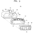
FIG. 3 is a partial, exploded perspective view of a dust separating unit of the stick type vacuum cleaner ofFIG. 1 ; -
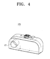
FIG. 4 is a perspective view illustrating a side cover of the dust separating unit ofFIG. 3 from different direction; -
FIG. 5 is a cross-section view taken on line V-V ofFIG. 1 ; and -
FIG. 6 is a cross-section view taken on line VI-VI ofFIG. 1 . - Throughout the drawings, the same drawing reference numerals will be understood to refer to the same elements, features, and structures.
- The matters defined in the description such as a detailed construction and elements are provided to assist in a comprehensive understanding of exemplary embodiments of the disclosure. Accordingly, those of ordinary skill in the art will recognize that various changes and modifications of the embodiments described herein can be made without departing from the scope of the disclosure. Also, descriptions of well-known functions and constructions are omitted for clarity and conciseness.
- Referring to
FIGS. 1 and2 , a sticktype vacuum cleaner 1 according to an exemplary embodiment of the present disclosure includes asuction port assembly 100, and astick part 200. - The
suction port assembly 100 is disposed to be moved along an object being cleaned, and to draw in dust from the object and collect the drawn dust therein. Thestick part 200 is engaged with a rear portion of thesuction port assembly 100 to facilitate a user's operation of thesuction port assembly 100 along the object being cleaned. Thestick part 200 includes anengaging part 210 formed on a rear portion of thesuction port assembly 100, a stick-type extension part 220 extending from theengaging part 210, and ahandgrip 230 formed on an upper portion of the stick-type extension part 220. - Referring to
FIGS. 1 ,2 and6 , thesuction port assembly 100 includes acasing part 110, arotatable brush 120, arotatable brush motor 121, apower supply 130, a suctionforce generating unit 140, and a dust separatingunit 150. - Referring to
FIG. 1 , thecasing part 110 includes anupper casing 111 and alower casing 112. Theupper casing 111 includes a dust separating unit chamber S to receive the dust separatingunit 150 therein. Theupper casing 111 also includes a plurality ofair discharge holes 111a formed in a rear portion to permit the clean air to be discharged outside thesuction port assembly 100 after the dust is separated in the dust separatingunit 150. - Referring to
FIG. 6 , thelower casing 112 includes asuction port 112a formed on the front portion. Dust and air can be drawn into thesuction port assembly 100 through thesuction port 112a. - Referring to
FIGS. 2 and6 , therotatable brush 120 is formed on the front portion of thelower casing 112, to be disposed in thesuction port 112a. Therotatable brush 120 is rotated by therotatable brush motor 121, to hit with its lower portion the object being cleaned and remove dust from the object being cleaned. - The
rotatable brush motor 121 receives power supply from the power supply 130 (FIG. 6 ). Thepower supply 130 according to the exemplary embodiment of the present disclosure is implemented as areplaceable battery 130 mounted inside thecasing part 110. Thebattery 130 supplies power not only to therotatable brush motor 121, but also to asuction motor 141 which will be explained below. - Referring to
FIG. 2 , the suctionforce generating unit 140 includes thesuction motor 141, animpeller 142, and a suctionport connecting pipe 143. Thesuction motor 141 receives power from thebattery 130 to rotate theimpeller 142. Theimpeller 142 is rotated by thesuction motor 141 to generate a vacuum pressure, or suction force. The suctionport connecting pipe 143 connects thesuction port 112a and theimpeller 142 to guide the air and dust drawn from the object being cleaned into theimpeller 142. - The
suction port assembly 100 includes the suctionforce generating unit 140 and thebattery 130 to supply power to the suctionforce generating unit 140 to generate a suction force. Thevacuum cleaner 1 according to the exemplary embodiment of the present disclosure does not need a power line to receive external power. - Referring again to
FIG. 2 , the suctionforce generating unit 140 is arranged in front of thedust separating unit 150. That is, the suctionforce generating unit 140 is provided between thesuction port 112a and thedust separating unit 150. Air and dust are drawn through thesuction port 112a, and then pass the suctionforce generating unit 140 and flow into thedust separating unit 150. More specifically, air and dust drawn through thesuction port 112a flow into thedust separating unit 150 via theimpeller 142 provided in the suctionforce generating unit 140. Theimpeller 142 is arranged on a fluid passage that connects thesuction port 112a and thedust separating unit 150 according to the exemplary embodiment of the present disclosure. Therefore, theimpeller 142 operates as a bypass impeller, while the motor to drive this bypass impeller operates as a bypass motor. - In comparison with a vacuum cleaner in which the suction
force generating unit 140 is arranged in the rear portion of thedust separating unit 150, the vacuum cleaner according to the exemplary embodiment of the present disclosure can provide almost unaffected level of suction force to thesuction port 112a when thesuction motor 141 rotates theimpeller 142 with relatively slower speed. - Because the suction
force generating unit 140 is arranged in front of thedust separating unit 150, the vacuum pressure generated at the suctionforce generating unit 140 is transmitted to thesuction port 112a intact, that is, without being affected by thedust separating unit 150. Furthermore, because the suctionforce generating unit 140 is arranged in front of thedust separating unit 150, theimpeller 142 of the suctionforce generating unit 140 is able to draw in dust and air introduced through thesuction port 112a using not only vacuum pressure, but also mechanical friction. The mechanical friction of theimpeller 142 more specifically refers to a friction between air and dust with the rotating blades (not illustrated) of theimpeller 142, which provides a moving force in the direction of thedust separating unit 150. - If the suction
force generating unit 140 is arranged in back of thedust separating unit 150, the vacuum pressure generated by the suctionforce generating unit 140 can be transmitted to thesuction port 112a via thedust separating unit 150. Accordingly, thedust separating unit 150 has the loss of vacuum pressure while the vacuum pressure is transmitted from the suctionforce generating unit 140 to thesuction port 112a. Furthermore, if the suctionforce generating unit 140 is arranged in back of thedust separating unit 150, dust is filtered at thedust separating unit 150 already prior to arriving at the suctionforce generating unit 140, and therefore, it is impossible for theimpeller 142 to draw the dust into thedust separating unit 150 by mechanical friction. - As explained above, when the suction
force generating unit 140 is provided in front of thedust separating unit 150, theimpeller 142 can be rotated at a relatively slower speed than when the suctionforce generating unit 140 is provided in back of thedust separating unit 150, but without compromising the level of suction force provided to thesuction port 112a. Because thesuction motor 141 consumes less power to rotate theimpeller 142, the life span of thebattery 130 to supply power to thesuction motor 141 can be increased. Furthermore, because the rotational speed of theimpeller 142 decreases, less amount of noise is generated from the rotation of theimpeller 142. - Referring to
FIGS. 1 and3 , thedust separating unit 150 is removably mounted in the dust separating unit chamber (S) of theupper casing 111. Thedust separating unit 150 includes a cyclonedust separating unit 160, aside cover 170, afilter member 180, and afilter support member 190. - Referring to
FIG. 1 , the cyclonedust separating unit 160 includes acyclone inlet 162 formed in afirst side 160a. The dust and air, after passing through the suctionforce generating unit 140, are introduced into thecyclone chamber 163 through thecyclone inlet 162. - Referring to
FIGS. 3 and5 , the cyclonedust separating unit 160 includes acyclone chamber 163 and adust collecting chamber 164 both formed therein. Thecyclone chamber 163 separates, using a centrifugal force, dust from air that introduced through thecyclone inlet 162. Thedust collecting chamber 164 collects the dust separated from thecyclone chamber 163. Thecyclone chamber 163 and thedust collecting chamber 164 are arranged in parallel and divided from each other by asingle partition 165. Thecyclone chamber 163 and thedust collecting chamber 164 are open to asecond side 160b of the cyclonedust separating unit 160. - The cyclone
dust separating unit 160 includes a dustseparating unit handgrip 161 formed on anupper side 160c so that a user can grab it and carry thedust separating unit 150 with ease. Theupper side 160c of the cyclonedust separating unit 160 may be made out of a transparent material to allow observance of thecyclone chamber 163 and thedust collecting chamber 164 from outside. Accordingly, a user is able to see and check the dust separating performance of thecyclone chamber 163 and also check the amount of dust collected in thedust collecting chamber 164, without having to disassemble thedust separating unit 150. - Referring to
FIGS. 3 and4 , theside cover 170 covers thesecond side 160b of the cyclonedust separating unit 160. Theside cover 170 is detachably formed on the cyclonedust separating unit 160. If thedust collecting chamber 164 is full, the user detaches theside cover 170 from the cyclonedust separating unit 160 and empties thedust collecting chamber 170. Theside cover 170 includes anair discharge pipe 171 formed thereon. Accordingly, clean air is discharged from thecyclone chamber 163 to thefilter member 180 through theair discharge pipe 171 when dust is separated from the air. - Referring to
FIG. 3 , thefilter member 180 is disposed on anouter side 172 of theside cover 170 to filter remaining dust from the air received from thecyclone chamber 163. - The
filter member 180 is supported by thefilter support member 190 to remain engaged with theside cover 170. Thefilter support member 190 is detachably engaged with theside cover 170. Accordingly, if thefilter member 180 gets too dusty, thefilter support member 190 along with thefilter member 180 is removed through theside cover 170 and a user can remove dust from thefilter member 180. Thefilter support member 190 includes a plurality ofair holes 191 for air to pass after passing through thefilter member 180. - The operation of a stick type vacuum cleaner constructed as above according to the exemplary embodiments of the present disclosure will be explained below with reference to
FIGS. 2 ,5 and6 . - As a user drives a stick
type vacuum cleaner 1, therotatable brush motor 121 receives power from thebattery 130 to rotate therotatable brush 120. At the same time, thesuction motor 141 also receives power from thebattery 130 to rotate theimpeller 142. The rotation of theimpeller 142 generates a suction force (vacuum pressure), which is provided to thesuction port 112a through the suction port connecting pipe 143 (seeFIG. 2 ). - As explained above, because the suction
force generating unit 140 having thesuction motor 141 and theimpeller 142 is arranged between thedust separating unit 150 and thesuction port 112a, unaffected level of suction force can be provided to thesuction port 112a even when thesuction motor 141 rotates theimpeller 142 at a relatively lower speed. As a result, thebattery 130 to supply power to thesuction motor 141 can be used for a longer period of time. Furthermore, because theimpeller 142 rotates at a relatively slower speed, noise is reduced. - During cleaning, as a user moves the
suction port assembly 100 along an object being cleaned, air and dust are drawn through thesuction port 112a. Therotatable brush 120 hits the dust of the object being cleaned in rotating movement, to thereby facilitate the removal of the dust. As a result, more efficient cleaning is achieved. - The air and dust enter through the
suction port 112a, and are introduced into theimpeller 142 through the suction port connecting pipe 143 (seeFIG. 2 ). The air and dust are then guided to the back of the cleaner by not only the suction force, but also the mechanical friction with theimpeller 142, and guided to thecyclone inlet 162 of the cyclonedust separating unit 160. Because the air and dust are introduced into thecyclone inlet 162 by both the suction force and mechanical friction, output of thesuction motor 141 to rotate theimpeller 142 can be relatively reduced. - Referring to
FIG. 5 , air and dust enter thecyclone inlet 162 and rotate inside thecyclone chamber 163 towards theside cover 170. The dust is separated from the air by centrifugal force and collected in thedust collecting chamber 164. The clean air exits thecyclone chamber 163 through theair discharge pipe 171 formed on theside cover 170 and reaches thefilter member 180 engaged with theside cover 170. The air is secondly filtered as it passes through thefilter member 180 so that any remaining dust is separated. The clean resultant air is then passed through theair passing hole 191 of thefilter supporting member 190 and discharged out of thedust separating unit 150. The air then passes through the passages such as theair discharge hole 111a (seeFIG. 1 ) formed on a rear portion of theupper casing 111 and is discharged through thesuction port assembly 100. - Meanwhile, a user can observe the status of the
cyclone chamber 163 and thedust collecting chamber 164 disposed inside the cyclonedust separating unit 160 during cleaning process. If determined that thedust collecting chamber 164 needs emptying, the user separates thedust separating unit 150 from the dust separating unit chamber (S) (FIG. 1 ), removes the cyclonedust separating unit 160 and theside cover 170, and discards dust of thedust collecting chamber 164. The user may remove thefilter support member 190 together with thefilter member 180 from theside cover 170 to clean thefilter member 180. - While certain exemplary embodiments of the present disclosure have been shown and described with reference to certain preferred embodiments thereof, it will be understood by those skilled in the art that various changes in form and details may be made therein without departing from the scope of the disclosure as defined by the appended claims and their equivalents.
Claims (17)
- A stick type vacuum cleaner comprising:a suction port assembly (100) movable along an object being cleaned to draw in dust and air from the object; anda stick part (200) in which a first end is engaged with a first side of the suction port assembly (100) and a second end comprises a handgrip (230) so that a user can grip the handgrip (230) to move the suction port assembly(100) along the object being cleaned, wherein the suction port assembly comprises:a casing part (110) comprising a suction port (112a) through which the air and dust are drawn from the object being cleaned,a suction force generating unit (140) formed inside the casing part (110) to generate a suction force,a dust separating unit (150) to separate the dust from the drawn air and dust and accommodate the separated dust therein, anda power supply unit (130) to supply power to the suction force generating unit (140), andwherein the suction force generating unit (140) is disposed between the suction port (112a) and the dust separating unit (150) so that the drawn air and dust pass through the suction force generating unit (140) before being introduced into the dust separating unit (150).
- The stick type vacuum cleaner of claim 1, wherein the suction force generating unit (140) comprises:an impeller (142) exposed to a passage defined between the suction port (112a) and the dust separating unit (150), the impeller (142) being configured to generate the suction force by rotational movement; anda suction motor (141) to receive a power from the power supply unit (130) and rotate the impeller (142).
- The stick type vacuum cleaner of claim 1 or 2, wherein the dust separating unit (150) comprises:a cyclone chamber (163) to separate dust from the air and dust drawn through the suction port (112a) by using a centrifugal force; anda dust collecting chamber (164) to accommodate the dust separated from the cyclone chamber (163).
- The stick type vacuum cleaner of claim 3, wherein the dust separating unit (150) comprises:a cyclone dust separating unit (160) in which the cyclone chamber (163) and the dust collecting chamber (164) are arranged in parallel, in a manner such that a cyclone inlet (162) is formed on a first side (160a) and the cyclone chamber (163) and the dust collecting chamber (164) are open in a second side (160b); anda side cover (170) to cover the second side (160b) of the cyclone dust separating unit (160), the side cover (170) comprising an air discharge pipe (171) to guide the air to be discharged from the cyclone chamber (163).
- The stick type vacuum cleaner of claim 4, wherein the dust separating unit (150) comprises:a filter member (180) formed on an outer surface of the side cover (170) to filter remaining dust from the air being discharged from the cyclone chamber (163); anda filter support member (190) removably formed on the outer surface of the side cover (170) to support the filter member (180) formed on the side cover (170).
- The stick type vacuum cleaner of claim 5, wherein the filter support member (190) comprises at least one air passing hole (191).
- The stick type vacuum cleaner of any of claims 4 to 6, wherein an upper side (160c) of the cyclone dust separating unit (160) is made out of a transparent material to enable a user to see the cyclone chamber (163) and the dust collecting chamber (164) therethrough.
- The stick type vacuum cleaner of any of claims 1 to 7, wherein the casing part (110) comprises a dust separating unit chamber (S) so that the dust separating unit (150) is removably housed in the dust separating unit chamber.
- The stick type vacuum cleaner of any of claims 1 to 8, wherein the suction port assembly (100) further comprises:a rotatable brush (120) movably formed in the suction port (112a); anda rotatable brush motor (121) to drive the rotatable brush (120).
- The stick type vacuum cleaner of claim 9, wherein the rotatable brush motor (121) receives power from the power generating unit (130).
- The stick type vacuum cleaner of any of claims 1 to 10, wherein the stick part (200) comprises:an engaging part (210) engaged to the first side of the suction port assembly (100);a stick-type extension part (220) extended from the engaging part (210); andthe handgrip (230) formed on one end of the stick-type extension part (220).
- The stick type vacuum cleaner of any of claims 1 to 11, wherein the power supply unit (130) comprises a battery removably disposed inside the casing part (110).
- A stick type vacuum cleaner comprising:a stick-type extension part (220) having a handgrip part (230) formed at a first end thereof;a casing part (110) comprising a suction port (112a) and stick engaging part (210), the stick engaging part (210) being configured to engage a second end of the stick-type extension part (220);a suction force generating unit (140) inside the casing part (110) to generate a suction force, the suction force being configured to draw in air and dust from an object being cleaned through the suction port (112a);a dust separating unit (150) to separate and collect the dust from the air and dust; anda battery (130) removably inside the casing part (110), the battery (130) being configured to supply power to the suction force generating unit (140), wherein the suction force generating unit is disposed between the suction port (112a) and the dust separating unit (150) so that the drawn air and dust pass through the suction force generating unit (140) before being introduced into the dust separating unit (150).
- The stick type vacuum cleaner of claim 13, wherein the suction force generating unit (140) comprises:an impeller (142) exposed to a passage defined between the suction port (112a) and the dust separating unit (150), the impeller (142) being configured to generate the suction force by rotational movement; anda suction motor (141) to receive a power from the battery (130) and rotate the impeller (142).
- The stick type vacuum cleaner of claim 13 or 14, wherein the dust separating unit (150) comprises:a cyclone chamber (163) to separate dust from the air and dust drawn through the suction port (112a) by using a centrifugal force; anda dust collecting chamber (164) to accommodate the dust separated from the cyclone chamber (163).
- The stick type vacuum cleaner of any of claims 13 to 15, wherein the casing part (110) comprises a dust separating unit chamber (S) so that the dust separating unit (150) is removably housed in the dust separating unit chamber.
- The stick type vacuum cleaner of any of claim 13 to 16, wherein the casing part (110) further comprises:a rotatable brush (120) movably formed in the suction port (112a); anda rotatable brush motor (121) to drive the rotatable brush (120), wherein the rotatable brush motor receives power from the battery (130).
Applications Claiming Priority (1)
| Application Number | Priority Date | Filing Date | Title |
|---|---|---|---|
| KR1020070086690A KR101340423B1 (en) | 2007-08-28 | 2007-08-28 | A Stick Type Vacuum Cleaner |
Publications (3)
| Publication Number | Publication Date |
|---|---|
| EP2030543A2 true EP2030543A2 (en) | 2009-03-04 |
| EP2030543A3 EP2030543A3 (en) | 2010-02-03 |
| EP2030543B1 EP2030543B1 (en) | 2011-10-26 |
Family
ID=40029204
Family Applications (1)
| Application Number | Title | Priority Date | Filing Date |
|---|---|---|---|
| EP08006179A Ceased EP2030543B1 (en) | 2007-08-28 | 2008-03-28 | Stick type vacuum cleaner |
Country Status (5)
| Country | Link |
|---|---|
| US (1) | US20090056060A1 (en) |
| EP (1) | EP2030543B1 (en) |
| JP (1) | JP2009050687A (en) |
| KR (1) | KR101340423B1 (en) |
| RU (1) | RU2008126078A (en) |
Cited By (24)
| Publication number | Priority date | Publication date | Assignee | Title |
|---|---|---|---|---|
| EP2201880A2 (en) * | 2008-12-29 | 2010-06-30 | Samsung Gwangju Electronics Co., Ltd. | Vacuum cleaner having detachable dust separating unit |
| CN103027633A (en) * | 2011-09-30 | 2013-04-10 | 三星电子株式会社 | Robot cleaner |
| EP2581014A1 (en) * | 2011-10-12 | 2013-04-17 | Black & Decker Inc. | A vaccum cleaner |
| WO2016063001A1 (en) * | 2014-10-22 | 2016-04-28 | Dyson Technology Limited | A separator for removing dirt particles from an airflow |
| US10071328B2 (en) | 2014-10-22 | 2018-09-11 | Dyson Technology Limited | Apparatus for separating particles from a fluid |
| US10314448B2 (en) | 2016-02-29 | 2019-06-11 | Lg Electronics Inc. | Vacuum cleaner |
| US10314455B2 (en) | 2016-02-29 | 2019-06-11 | Lg Electronics Inc. | Vacuum cleaner |
| US10321796B2 (en) | 2016-02-29 | 2019-06-18 | Lg Electronics Inc. | Vacuum cleaner |
| US10357135B2 (en) | 2016-02-29 | 2019-07-23 | Lg Electronics Inc. | Vacuum cleaner |
| US10362915B2 (en) | 2016-02-29 | 2019-07-30 | Lg Electronics Inc. | Vacuum cleaner |
| US10398272B2 (en) | 2016-05-03 | 2019-09-03 | Lg Electronics Inc. | Vacuum cleaner |
| US10426310B2 (en) | 2016-02-29 | 2019-10-01 | Lg Electronics Inc. | Vacuum cleaner |
| US10426303B2 (en) | 2016-02-29 | 2019-10-01 | Lg Electronics Inc. | Vacuum cleaner |
| US10433693B2 (en) | 2016-02-29 | 2019-10-08 | Lg Electronics Inc. | Vacuum cleaner |
| US10506905B2 (en) | 2016-02-29 | 2019-12-17 | Lg Electronics Inc. | Vacuum cleaner |
| US10517451B2 (en) | 2016-05-20 | 2019-12-31 | Lg Electronics Inc. | Vacuum cleaner |
| US10555651B2 (en) | 2014-10-22 | 2020-02-11 | Dyson Technology Limited | Apparatus for separating particles from an airflow |
| US10575690B2 (en) | 2016-02-29 | 2020-03-03 | Lg Electronics Inc. | Vacuum cleaner |
| US10582822B2 (en) | 2016-02-29 | 2020-03-10 | Lg Electronics Inc. | Vacuum cleaner |
| US10682029B2 (en) | 2016-02-29 | 2020-06-16 | Lg Electronics Inc. | Vacuum cleaner |
| US10758101B2 (en) | 2017-06-12 | 2020-09-01 | Emerson Electric Co. | Upright vacuum cleaner with battery support plate |
| US10856711B2 (en) | 2016-05-03 | 2020-12-08 | Lg Electronics Inc. | Vacuum cleaner |
| US10945570B2 (en) | 2016-02-29 | 2021-03-16 | Lg Electronics Inc. | Vacuum cleaner |
| US11311162B2 (en) | 2016-05-03 | 2022-04-26 | Lg Electronics Inc. | Vacuum cleaner |
Families Citing this family (42)
| Publication number | Priority date | Publication date | Assignee | Title |
|---|---|---|---|---|
| JP4770821B2 (en) * | 2007-11-16 | 2011-09-14 | パナソニック株式会社 | Vacuum cleaner |
| US8316506B1 (en) * | 2008-05-28 | 2012-11-27 | Spalj Thomas J | Surface debris removal apparatus |
| US8062398B2 (en) * | 2008-12-19 | 2011-11-22 | Bissell Homecare, Inc. | Vacuum cleaner and cyclone module therefor |
| US9265395B2 (en) * | 2010-03-12 | 2016-02-23 | Omachron Intellectual Property Inc. | Surface cleaning apparatus |
| US9433332B2 (en) | 2013-02-27 | 2016-09-06 | Omachron Intellectual Property Inc. | Surface cleaning apparatus |
| US8578555B2 (en) * | 2010-03-12 | 2013-11-12 | G.B.D. Corp. | Surface cleaning apparatus |
| US8887349B2 (en) * | 2009-04-16 | 2014-11-18 | Lg Electronics Inc. | Vacuum cleaner |
| JP5710203B2 (en) * | 2010-01-29 | 2015-04-30 | サムスン エレクトロニクス カンパニー リミテッド | Vacuum cleaner brush assembly |
| US8813305B2 (en) * | 2010-03-12 | 2014-08-26 | G.B.D. Corp. | Compact surface cleaning apparatus |
| US20130133155A1 (en) * | 2011-11-28 | 2013-05-30 | Julio C. Perez | Vacuum cleaner incorporating noise suppression system |
| US9320401B2 (en) | 2013-02-27 | 2016-04-26 | Omachron Intellectual Property Inc. | Surface cleaning apparatus |
| US9591958B2 (en) | 2013-02-27 | 2017-03-14 | Omachron Intellectual Property Inc. | Surface cleaning apparatus |
| KR102180682B1 (en) * | 2014-06-13 | 2020-11-20 | 삼성전자주식회사 | Robot Cleaner |
| US11202544B2 (en) | 2014-12-17 | 2021-12-21 | Omachron Intellectual Property Inc. | All in the head surface cleaning apparatus |
| US9668630B2 (en) * | 2014-12-17 | 2017-06-06 | Omachron Intellectual Property Inc. | All in the head surface cleaning apparatus |
| GB2539060B (en) * | 2014-12-17 | 2017-11-08 | Omachron Intellectual Property Inc | All in the head surface cleaning apparatus |
| US9883781B2 (en) * | 2014-12-17 | 2018-02-06 | Omachron Intellectual Property Inc. | All in the head surface cleaning apparatus |
| US10022027B2 (en) | 2014-12-17 | 2018-07-17 | Omachron Intellectual Property Inc. | All in the head surface cleaning apparatus |
| US9295363B1 (en) * | 2014-12-17 | 2016-03-29 | Omachron Intellectual Property Inc. | All in the head surface cleaning apparatus |
| US9775481B2 (en) * | 2014-12-17 | 2017-10-03 | Omachron Intellectual Property Inc. | All in the head surface cleaning apparatus |
| US9717383B2 (en) | 2014-12-17 | 2017-08-01 | Omachron Intellectual Property Inc. | All in the head surface cleaning apparatus |
| US9775479B2 (en) | 2014-12-17 | 2017-10-03 | Omachron Intellectual Property Inc. | All in the head surface cleaning apparatus |
| US9795264B2 (en) * | 2014-12-17 | 2017-10-24 | Omachron Intellectual Property Inc. | All in the head surface cleaning apparatus |
| US9668624B2 (en) | 2014-12-17 | 2017-06-06 | Omachron Intellectual Property Inc. | All in the head surface cleaning apparatus |
| US9545180B2 (en) | 2014-12-17 | 2017-01-17 | Omachron Intellectual Property Inc. | All in the head surface cleaning apparatus |
| US9775480B2 (en) | 2014-12-17 | 2017-10-03 | Omachron Intellectual Property Inc. | All in the head surface cleaning apparatus |
| US9901229B2 (en) | 2014-12-17 | 2018-02-27 | Omachron Intellectual Property Inc. | All in the head surface cleaning apparatus |
| US10357136B2 (en) | 2014-12-17 | 2019-07-23 | Omachron Intellectual Property Inc. | All in the head surface cleaning apparatus |
| CN108135414B (en) * | 2015-08-06 | 2022-01-04 | 尚科宁家运营有限公司 | Low profile surface cleaning head |
| TWI637715B (en) * | 2016-02-29 | 2018-10-11 | Lg電子股份有限公司 | Vacuum cleaner |
| DE202017000984U1 (en) * | 2016-02-29 | 2017-05-29 | Lg Electronics Inc. | vacuum cleaner |
| US10271702B2 (en) | 2016-05-03 | 2019-04-30 | Lg Electronics Inc. | Vacuum cleaner |
| US10299646B2 (en) | 2016-05-03 | 2019-05-28 | Lg Electronics Inc. | Vacuum cleaner |
| US10299647B2 (en) | 2016-05-03 | 2019-05-28 | Lg Electronics Inc. | Vacuum cleaner |
| US11980334B2 (en) * | 2017-09-15 | 2024-05-14 | Omachron Intellectual Property Inc. | Surface cleaning apparatus |
| US11478116B2 (en) | 2018-01-15 | 2022-10-25 | Omachron Intellectual Property Inc | Surface cleaning apparatus |
| GB201812610D0 (en) * | 2018-08-02 | 2018-09-19 | Grey Technology Ltd | Battery-powered vaccum cleaner |
| US11192122B2 (en) | 2018-08-13 | 2021-12-07 | Omachron Intellectual Property Inc. | Cyclonic air treatment member and surface cleaning apparatus including the same |
| US11006799B2 (en) | 2018-08-13 | 2021-05-18 | Omachron Intellectual Property Inc. | Cyclonic air treatment member and surface cleaning apparatus including the same |
| US11013384B2 (en) | 2018-08-13 | 2021-05-25 | Omachron Intellectual Property Inc. | Cyclonic air treatment member and surface cleaning apparatus including the same |
| CA3060770A1 (en) * | 2018-10-30 | 2020-04-30 | Shop Vac Corporation | Filter system for a vacuum cleaner |
| CN112971605A (en) * | 2019-12-13 | 2021-06-18 | 江苏美的清洁电器股份有限公司 | Dust cup and dust collector with same |
Citations (1)
| Publication number | Priority date | Publication date | Assignee | Title |
|---|---|---|---|---|
| WO2006106278A1 (en) | 2005-04-08 | 2006-10-12 | Grey Technology Limited | Surface cleaning apparatus |
Family Cites Families (12)
| Publication number | Priority date | Publication date | Assignee | Title |
|---|---|---|---|---|
| US5014388A (en) * | 1989-05-15 | 1991-05-14 | White Consolidated Industries, Inc. | Battery powered vacuum cleaner |
| US5664285A (en) * | 1996-01-11 | 1997-09-09 | Black & Decker Inc. | Vacuum cleaner with combined filter element and collection unit |
| KR20000011440A (en) * | 1998-07-06 | 2000-02-25 | 마츠시타 덴끼 산교 가부시키가이샤 | Vacuum cleaner |
| CA2289808A1 (en) * | 1998-11-18 | 2000-05-18 | Arnold L. Sepke | Battery power combination vacuum cleaner |
| TW529406U (en) * | 1999-01-29 | 2003-04-21 | Hitachi Ltd | Vacuum cleaner |
| US6596044B1 (en) * | 2000-03-06 | 2003-07-22 | The Hoover Company | Dirt collecting system for a vacuum cleaner |
| JP2003010076A (en) | 2001-06-27 | 2003-01-14 | Figla Co Ltd | Vacuum cleaner |
| WO2005096907A1 (en) * | 2004-04-08 | 2005-10-20 | Grey Technology Limited | Surface cleaning apparatus |
| US7547336B2 (en) | 2004-12-13 | 2009-06-16 | Bissell Homecare, Inc. | Vacuum cleaner with multiple cyclonic dirt separators and bottom discharge dirt cup |
| KR20070106526A (en) * | 2005-01-18 | 2007-11-01 | 일렉트로룩스 홈 케어 프로덕츠, 인크. | Vacuum cleaner with collapsible handle |
| US7410516B2 (en) * | 2005-03-17 | 2008-08-12 | Royal Appliance Mfg. Co. | Twin cyclone vacuum cleaner |
| KR101472770B1 (en) * | 2008-02-18 | 2014-12-17 | 삼성전자주식회사 | Cleaner Apparatus |
-
2007
- 2007-08-28 KR KR1020070086690A patent/KR101340423B1/en not_active IP Right Cessation
-
2008
- 2008-02-21 US US12/070,763 patent/US20090056060A1/en not_active Abandoned
- 2008-03-28 EP EP08006179A patent/EP2030543B1/en not_active Ceased
- 2008-06-20 JP JP2008161551A patent/JP2009050687A/en active Pending
- 2008-06-27 RU RU2008126078/12A patent/RU2008126078A/en not_active Application Discontinuation
Patent Citations (1)
| Publication number | Priority date | Publication date | Assignee | Title |
|---|---|---|---|---|
| WO2006106278A1 (en) | 2005-04-08 | 2006-10-12 | Grey Technology Limited | Surface cleaning apparatus |
Cited By (29)
| Publication number | Priority date | Publication date | Assignee | Title |
|---|---|---|---|---|
| EP2201880A3 (en) * | 2008-12-29 | 2012-09-26 | Samsung Electronics Co., Ltd. | Vacuum cleaner having detachable dust separating unit |
| EP2201880A2 (en) * | 2008-12-29 | 2010-06-30 | Samsung Gwangju Electronics Co., Ltd. | Vacuum cleaner having detachable dust separating unit |
| CN103027633A (en) * | 2011-09-30 | 2013-04-10 | 三星电子株式会社 | Robot cleaner |
| CN103027633B (en) * | 2011-09-30 | 2016-12-21 | 三星电子株式会社 | Robot cleaner |
| EP2581014A1 (en) * | 2011-10-12 | 2013-04-17 | Black & Decker Inc. | A vaccum cleaner |
| US10555651B2 (en) | 2014-10-22 | 2020-02-11 | Dyson Technology Limited | Apparatus for separating particles from an airflow |
| WO2016063001A1 (en) * | 2014-10-22 | 2016-04-28 | Dyson Technology Limited | A separator for removing dirt particles from an airflow |
| CN105534401A (en) * | 2014-10-22 | 2016-05-04 | 戴森技术有限公司 | Separator for removing dirt particles from an airflow |
| US10071328B2 (en) | 2014-10-22 | 2018-09-11 | Dyson Technology Limited | Apparatus for separating particles from a fluid |
| US10143346B2 (en) | 2014-10-22 | 2018-12-04 | Dyson Technology Limited | Separator for removing dirt particles from an airflow |
| US10575690B2 (en) | 2016-02-29 | 2020-03-03 | Lg Electronics Inc. | Vacuum cleaner |
| US10682029B2 (en) | 2016-02-29 | 2020-06-16 | Lg Electronics Inc. | Vacuum cleaner |
| US10357135B2 (en) | 2016-02-29 | 2019-07-23 | Lg Electronics Inc. | Vacuum cleaner |
| US10362915B2 (en) | 2016-02-29 | 2019-07-30 | Lg Electronics Inc. | Vacuum cleaner |
| US11039724B2 (en) | 2016-02-29 | 2021-06-22 | Lg Electronics Inc. | Vacuum cleaner |
| US10426310B2 (en) | 2016-02-29 | 2019-10-01 | Lg Electronics Inc. | Vacuum cleaner |
| US10426303B2 (en) | 2016-02-29 | 2019-10-01 | Lg Electronics Inc. | Vacuum cleaner |
| US10433693B2 (en) | 2016-02-29 | 2019-10-08 | Lg Electronics Inc. | Vacuum cleaner |
| US10506905B2 (en) | 2016-02-29 | 2019-12-17 | Lg Electronics Inc. | Vacuum cleaner |
| US10945570B2 (en) | 2016-02-29 | 2021-03-16 | Lg Electronics Inc. | Vacuum cleaner |
| US10314455B2 (en) | 2016-02-29 | 2019-06-11 | Lg Electronics Inc. | Vacuum cleaner |
| US10314448B2 (en) | 2016-02-29 | 2019-06-11 | Lg Electronics Inc. | Vacuum cleaner |
| US10582822B2 (en) | 2016-02-29 | 2020-03-10 | Lg Electronics Inc. | Vacuum cleaner |
| US10321796B2 (en) | 2016-02-29 | 2019-06-18 | Lg Electronics Inc. | Vacuum cleaner |
| US10856711B2 (en) | 2016-05-03 | 2020-12-08 | Lg Electronics Inc. | Vacuum cleaner |
| US10398272B2 (en) | 2016-05-03 | 2019-09-03 | Lg Electronics Inc. | Vacuum cleaner |
| US11311162B2 (en) | 2016-05-03 | 2022-04-26 | Lg Electronics Inc. | Vacuum cleaner |
| US10517451B2 (en) | 2016-05-20 | 2019-12-31 | Lg Electronics Inc. | Vacuum cleaner |
| US10758101B2 (en) | 2017-06-12 | 2020-09-01 | Emerson Electric Co. | Upright vacuum cleaner with battery support plate |
Also Published As
| Publication number | Publication date |
|---|---|
| US20090056060A1 (en) | 2009-03-05 |
| JP2009050687A (en) | 2009-03-12 |
| KR20090021839A (en) | 2009-03-04 |
| RU2008126078A (en) | 2010-01-10 |
| EP2030543B1 (en) | 2011-10-26 |
| EP2030543A3 (en) | 2010-02-03 |
| KR101340423B1 (en) | 2013-12-13 |
Similar Documents
| Publication | Publication Date | Title |
|---|---|---|
| EP2030543B1 (en) | Stick type vacuum cleaner | |
| KR100615360B1 (en) | Cyclone dust collecting device and vacuum cleaner having the same | |
| US7682414B2 (en) | Dust collecting unit for use in cleaner | |
| JP2006110320A (en) | Cyclone dust collector and vacuum cleaner having it | |
| JP4482034B2 (en) | Vacuum cleaning head | |
| GB2447716A (en) | Upright vacuum cleaner | |
| US12059122B2 (en) | Dust collector and cleaner having the same | |
| KR101392428B1 (en) | vacuum cleaner | |
| KR20050013696A (en) | Dust removing unit in vacuum cleaner | |
| KR20060128387A (en) | Vacuum cleaner | |
| JP2009504235A (en) | Vacuum cleaner filter mounting structure | |
| TWI825605B (en) | Cleaner | |
| KR100992221B1 (en) | Vacuum cleaner | |
| US20070039124A1 (en) | Exhaust structure of vacuum cleaner | |
| KR101248475B1 (en) | Vacuum cleaner | |
| KR100587098B1 (en) | Sealing structure of dust removing unit in vacuum cleaner | |
| KR20070087357A (en) | Vacuum cleaner | |
| EP3636126B1 (en) | A vacuum cleaner | |
| JP5040344B2 (en) | Electric vacuum cleaner | |
| KR20090071234A (en) | Vacuum cleaner | |
| JP2008289764A (en) | Vacuum cleaner | |
| KR101108048B1 (en) | Dust Collecting Device for Cleaner | |
| KR200306319Y1 (en) | Vacuum cleaning appointment suction head the brush is had built-in | |
| KR20100138837A (en) | Dust collecting apparatus and electric cleaner | |
| KR100751813B1 (en) | Dustbin and vacuum cleaner therewith |
Legal Events
| Date | Code | Title | Description |
|---|---|---|---|
| PUAI | Public reference made under article 153(3) epc to a published international application that has entered the european phase |
Free format text: ORIGINAL CODE: 0009012 |
|
| AK | Designated contracting states |
Kind code of ref document: A2 Designated state(s): AT BE BG CH CY CZ DE DK EE ES FI FR GB GR HR HU IE IS IT LI LT LU LV MC MT NL NO PL PT RO SE SI SK TR |
|
| AX | Request for extension of the european patent |
Extension state: AL BA MK RS |
|
| PUAL | Search report despatched |
Free format text: ORIGINAL CODE: 0009013 |
|
| AK | Designated contracting states |
Kind code of ref document: A3 Designated state(s): AT BE BG CH CY CZ DE DK EE ES FI FR GB GR HR HU IE IS IT LI LT LU LV MC MT NL NO PL PT RO SE SI SK TR |
|
| AX | Request for extension of the european patent |
Extension state: AL BA MK RS |
|
| 17P | Request for examination filed |
Effective date: 20100323 |
|
| AKX | Designation fees paid |
Designated state(s): DE GB |
|
| GRAP | Despatch of communication of intention to grant a patent |
Free format text: ORIGINAL CODE: EPIDOSNIGR1 |
|
| RIC1 | Information provided on ipc code assigned before grant |
Ipc: A47L 9/16 20060101ALI20110427BHEP Ipc: A47L 5/28 20060101ALI20110427BHEP Ipc: A47L 5/12 20060101AFI20110427BHEP |
|
| RAP1 | Party data changed (applicant data changed or rights of an application transferred) |
Owner name: SAMSUNG ELECTRONICS CO., LTD. |
|
| GRAS | Grant fee paid |
Free format text: ORIGINAL CODE: EPIDOSNIGR3 |
|
| GRAA | (expected) grant |
Free format text: ORIGINAL CODE: 0009210 |
|
| AK | Designated contracting states |
Kind code of ref document: B1 Designated state(s): DE GB |
|
| REG | Reference to a national code |
Ref country code: GB Ref legal event code: FG4D |
|
| REG | Reference to a national code |
Ref country code: DE Ref legal event code: R096 Ref document number: 602008010702 Country of ref document: DE Effective date: 20120105 |
|
| PLBE | No opposition filed within time limit |
Free format text: ORIGINAL CODE: 0009261 |
|
| STAA | Information on the status of an ep patent application or granted ep patent |
Free format text: STATUS: NO OPPOSITION FILED WITHIN TIME LIMIT |
|
| RAP2 | Party data changed (patent owner data changed or rights of a patent transferred) |
Owner name: SAMSUNG ELECTRONICS CO., LTD. |
|
| 26N | No opposition filed |
Effective date: 20120727 |
|
| REG | Reference to a national code |
Ref country code: DE Ref legal event code: R097 Ref document number: 602008010702 Country of ref document: DE Effective date: 20120727 |
|
| PGFP | Annual fee paid to national office [announced via postgrant information from national office to epo] |
Ref country code: GB Payment date: 20200225 Year of fee payment: 13 Ref country code: DE Payment date: 20200220 Year of fee payment: 13 |
|
| REG | Reference to a national code |
Ref country code: DE Ref legal event code: R119 Ref document number: 602008010702 Country of ref document: DE |
|
| GBPC | Gb: european patent ceased through non-payment of renewal fee |
Effective date: 20210328 |
|
| PG25 | Lapsed in a contracting state [announced via postgrant information from national office to epo] |
Ref country code: DE Free format text: LAPSE BECAUSE OF NON-PAYMENT OF DUE FEES Effective date: 20211001 Ref country code: GB Free format text: LAPSE BECAUSE OF NON-PAYMENT OF DUE FEES Effective date: 20210328 |